
VF-AT-NBC - Mount Atdec - Free user manual and instructions
Find the device manual for free VF-AT-NBC Atdec in PDF.


| Product Type | Notebook/Monitor Arm Combo |
| Brand | Atdec |
| Model | VF-AT-NBC |
| Maximum Load Capacity | 8 kg (17.6 lbs) |
| Mounting Options | Bolt Through (requires 9mm hole) or Desk Clamp |
| Desk Clamp Thickness Range | Up to 99 mm (depending on bracket position) |
| VESA Compatibility | 75x75 mm and 100x100 mm |
| Height Adjustment | Yes, via handgrips |
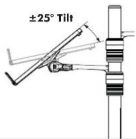
| Tilt Adjustment (Monitor) | ±25° |
| Pan Adjustment (Monitor) | ±95° rotation, ±5° horizontal adjustment |
| Tilt Adjustment (Notebook Tray) | Yes, using 5mm Allen key |
| Notebook Tray Support | Adjustable support tabs with hook-and-loop fasteners |
| Cable Management | Included cable covers, clips, and stops |
| Pole Top Cap | Stores Allen key |
| Included Tools | 5mm Allen key (additional: power drill for bolt through) |
| Recommended Viewing Distance | 500-750 mm (20-29.5 inches) |
| Recommended Monitor Height (from desk) | 356-560 mm depending on user height |
| User Height Range | Short Female: 356 mm; Tall Male: 560 mm |
Frequently Asked Questions - VF-AT-NBC Atdec
User questions about VF-AT-NBC Atdec
0 question about this device. Answer the ones you know or ask your own.
Ask a new question about this device
Download the instructions for your Mount in PDF format for free! Find your manual VF-AT-NBC - Atdec and take your electronic device back in hand. On this page are published all the documents necessary for the use of your device. VF-AT-NBC by Atdec.
USER MANUAL VF-AT-NBC Atdec
Notebook Tray and Arm Assembly

Arm Assembly
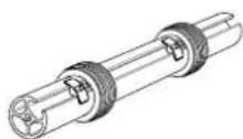
Pole Assembly

Desk Clamp
Assembly
HARDWARE
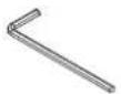
5mm Allen Key
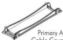
Primary Arm Cable Cover (x2)

Hook & Loop
Fasteners (x4 sets)
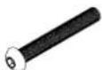
M8 x 60mm
Button Head Screw

Cable Stops (x2)

Pole Top Cap
Display Mounting Screws

M4x10/12/16mm (x4)
Phillips Head Mounting Screws

Secondary Arm Cable Cover (x2)

Steel Washer

M8 x 30mm
Screw

Cable Clips (x2)

Bolt Through Base
Tools Required:
- Power Drill
- 9mm (0.35") Drill Bit
• Phillips Head Screwdriver
IMPORTANT INFORMATION:
! IMPORTANT - Install Visidec Focus Notebook/Monitor Arm Combo as per installation instruction.
! This product supports a maximum load of 8kg (17.6lbs).
! The manufacturer accepts no responsibility for incorrect installation.
Step 1. Check Components
Check what you have received against the component checklist and hardware above.
Step 2. Mount Pole Assembly
Option 1: Bolt Through
1.1 Drill a 9mm (0.35") hole in the work surface in the desired position and assemble as shown below.
It is recommended that the Pole Assembly be mounted towards the rear edge of the work surface.

Option 2: Mount using Desk Clamp
2.1 Remove both the Pressure plate and M10 Desk Clamp Screw.
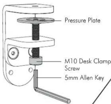
2.2 Fasten the Desk Clamp to the Bolt Through Base & Pole Assembly using the M8 x 30mm Screw and Tighten Firmly.

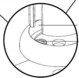
Note: Ensure that the Slot Tab in the Bolt Through Base fits snugly into the Slot on the Pole Assembly.
The Visidec logo on the Bolt Through Base must face the front of this assembly.
Step 2. Mount Pole Assembly (cont.)
2.3 The Desk Clamp bracket can be repositioned to suit different mounting surface thicknesses. The maximum mounting surface thicknesses supported are listed below from the Top to Middle and Bottom Screw Holes.
If you need to reposition the desk clamp bracket or you have no access to the rear of your table continue to Step 2.4. If you DO NOT need to reposition the desk clamp bracket and you have access to the rear of your table skip to Step 2.7.
2.4 Remove the M8 x 16mm Socket Head Countersunk Screws to release the Desk Clamp Bracket.
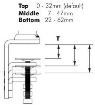
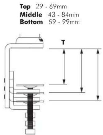
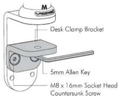

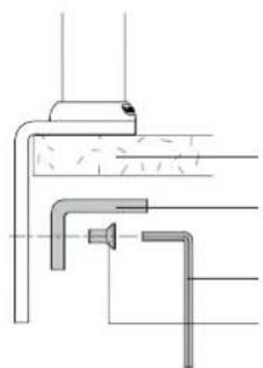
2.6 Reattach Desk Clamp Bracket. Table Top Desk Clamp Bracket 5mm Allen Key M8 x 16mm Socket Head Countersunk Screw
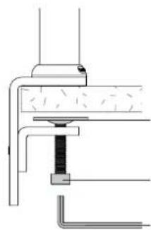
2.7 After positioning your Pole Assembly, screw Pressure Plate in and Tighten Firmly. Pressure Plate M10 Desk Clamp Screw 5mm Allen Key
Step 3. Mount Notebook Tray Arm

3.1 Unlock 1st Handgrip and remove from Pole Assembly.

3.2 Unlock 2nd Handgrip and raise so that Handgrip Tab protrudes.
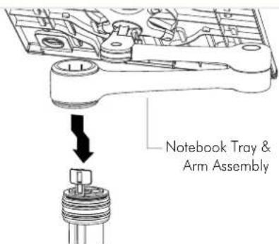
3.3 Slip the Notebook Tray & Arm Assembly over the Handgrip Tab and then onto the Pole.

3.4 Slide the Notebook Tray & Arm Assembly and Handgrip down the pole before locking the handgrip at the desired height.
Step 4. Mount Arm Assembly
Handgrip Tab

4.1 Reinstall Handgrip so that Handgrip Tab protrudes.

4.2 Slip the Arm Assembly over the Handgrip Tab and then onto the Pole.
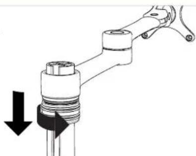
4.3 Slide the Arm Assembly and Handgrip down the pole before locking the handgrip at the desired height.
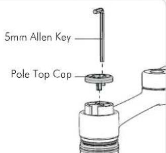
4.4 Insert Pole Top Cap into Pole. This is also where the Allen Key is stored.
Step 5. Install Notebook Step 6. Mount Display

5.1 Adjust the Support Tabs to suit the width of the Notebook Computer ensuring that cable ports are not obstructed.
5.2 To increase stability, use the self adhesive Hook-and-Loop Fasteners supplied.
- Peel off the backing paper to the fasteners.
- Attach fasteners to both the Notebook Tray and Computer.
- Ensure that each set of fasteners are correctly aligned i.e. Hook to Loop.

Option 1: 75x75mm Hole Pattern

Option 2: 100x100mm Hole Pattern
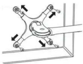
Note: Extend Arms to achieve 100x100mm hole pattern.
Step 7. Adjust Height

7.1 Unlock Handgrip ensuring Screen or Notebook Tray and Arm Assembly are supported.

7.2 Lift/Lower Screen or Notebook Tray to the desired height. Move both Screen and Arm assembly together.

7.3 Lock Handgrip firmly.
Step 8. Cable Management
8.1 After plugging in your cables, install the Cable Covers.

8.2 Cable Clips and Cable Stops can be installed to further manage cables. Please See Over.
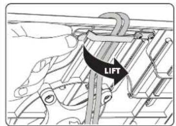
Note: After connecting the Notebook Cables, route them through the Cable Management Clip on the back of the Notebook Tray.

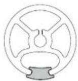
Step 8.2. Insert Cable Stops

A. Insert Cable Stop on one edge of the Pole Slot.

B. Press down firmly onto the other edge of the Cable Stop and hold. This allows the rear profile to flex in place.
Step 9. Adjusting the Display Bracket


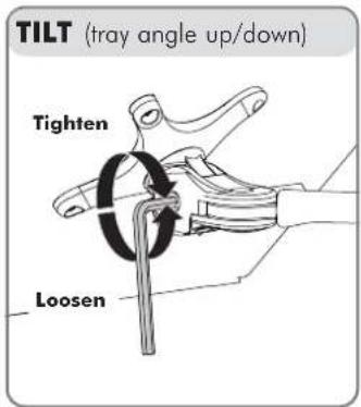


Adjust the tilt angle of the Notebook Tray as desired, locking it in position using the 5mm Allen Key.
The height can be adjusted by unlocking the Handgrips (see Step 7). For the optimal position of your display, refer to the Ergonomic Guidelines below.
Ergonomic Guidelines
Many experts believe that the extended use of any computer screen has the potential to cause serious injury to your eyes, neck and back. This can be largely avoided by correctly positioning your display.
Viewing angle: Ergonomists recommend that the optimal position of your display should be slightly below eye level. When looking at the display's centre the user should have a downward visual angle of approximately 10°-20° .
Height: As a guide, the height (h) of your display should approximately be as follows:
- Tall Male (Max): 560mm (22")
- Short Male (Min): 368mm (14.5")
- Tall Female (Max): 520mm (20.5")
- Short Female (Min) 356mm (14")
Distance: For visual comfort, a viewing distance (d) between 500mm (20") to 750mm (29.5") is recommended.
Tilt Angle: Angular adjustments to reduce reflection on your monitor should range between 5° forward tilt to 15° backward tilt.


- TOOLS REQUIRED
- IMPORTANT INFORMATION
- STEP 1. CHECK COMPONENTS
- STEP 2. MOUNT POLE ASSEMBLY
- STEP 2. MOUNT POLE ASSEMBLY (CONT.)
- STEP 3. MOUNT NOTEBOOK TRAY ARM
- STEP 4. MOUNT ARM ASSEMBLY
- STEP 5. INSTALL NOTEBOOK STEP 6. MOUNT DISPLAY
- STEP 7. ADJUST HEIGHT
- STEP 8. CABLE MANAGEMENT
- STEP 8.2. INSERT CABLE STOPS
- STEP 9. ADJUSTING THE DISPLAY BRACKET
- ERGONOMIC GUIDELINES
Brand : Atdec
Model : VF-AT-NBC
Category : Mount