
URC-125CS - Air Conditioning ActronAir - Free user manual and instructions
Find the device manual for free URC-125CS ActronAir in PDF.


| Product Type | Universal Wired Remote Controller |
| Brand | ActronAir |
| Model | URC-125CS |
| Dimensions (H x W x D) | 123 mm x 83.5 mm x 18.5 mm |
| Weight | Approx. 200 g |
| Power Supply | DC 12V from indoor unit |
| Display | LCD display with temperature, timer, and error codes |
| Operating Temperature | 5°C to 43°C |
| Operating Humidity | RH40% to RH90% |
| Wiring Type | 4-core shielded cable, max 50 m with 1.5 mm² wire |
| Battery (Clock Backup) | 1 x CR2032 lithium battery |
| Modes | Auto, Cool, Dry, Heat, Fan |
| Fan Speeds | Auto, Low, Med, High |
| Swing Functions | Up-down and left-right swing (depending on indoor unit) |
| Timer Functions | On timer, Off timer, Weekly timer (up to 8 events per day) |
| Special Features | Follow me, Child lock, Turbo, Elevating panel (cassette models) |
| Error Code Display | Yes (e.g., E0, E1, etc.) |
| Safety Compliance | Must be installed by a licensed electrician per local regulations |
| Cleaning Instructions | Clean with a soft, dry cloth; do not use water or chemicals |
Frequently Asked Questions - URC-125CS ActronAir
User questions about URC-125CS ActronAir
0 question about this device. Answer the ones you know or ask your own.
Ask a new question about this device
Download the instructions for your Air Conditioning in PDF format for free! Find your manual URC-125CS - ActronAir and take your electronic device back in hand. On this page are published all the documents necessary for the use of your device. URC-125CS by ActronAir.
USER MANUAL URC-125CS ActronAir
INSTALLATION & OWNER'S MANUAL
Universal Wired Remote Controller

Model Number: WC-02
IMPORTANT NOTE:
Please read this manual carefully before installing or operating your wired remote controller. Make sure to save this manual for future reference.
Table of Contents
Installation and Owner's Manual
- Safety Precaution.... 3
- Installation Components.... 4
- Installation Method.... 5
- Specification.... 10
- Wired Controller Features and Functions.... 11
- Wired Controller Display.... 12
- Wired Controller Buttons.... 13
- Preparatory Operation.... 14
- Operation.... 15
- Timer Functions 20
- Weekly Timer.... 23
- Fault Alarm Handing 30
1. Safety Precautions
Controller
- This manual gives detailed description of the precautions that should be brought to your attention during operation.
- To ensure the correct service of the wired controller read this manual carefully before using the unit.
- Keep this manual after reading for future reference.

WARNING
- Carefully read the Safety Precautions before installation. Adhere to this installation manual.
- Only trained and qualified HVAC technicians should install, repair and service this air conditioning unit, strictly follow the installation instructions set forth in this manual. Improper installation may result in electrical shock, short circuit, leaks, fire or other damage to the equipment and personal property.
- Reinstallation must be performed by a qualified service technician.
WARNINGS FOR PRODUCT USE
- DO NOT install the unit in a place vulnerable to leakage of flammable gases. If flammable gases leak or linger around the wired controller, fire may occur.
• CODES, REGULATIONS, AND STANDARDS
The installer/contractor assumes responsibility to ensure that the installation complies with the relevant council, state/federal codes, regulations and building code standards. All electrical wiring must be in accordance with current electrical authority regulations and all wiring connections to be as per the electrical diagram/s provided with the unit.
FOR COMPLIANCE WITH
QUEENSLAND ELECTRICAL SAFETY
REGULATIONS 2002
This refers to electrical works only

MUST BE INSTALLED BY A
LICENSED ELECTRICIAN
Read Safety Precautions Before Installation
Thank you for purchasing this air conditioner. This manual will provide you with information on how to operate, maintain, and troubleshoot your air conditioner. Following the instructions will ensure the proper function and extended lifespan of your unit.
Please pay attention to the following signs:

WARNING
Failure to observe a warning may result in death or serious injury. The appliance must be installed in accordance with national regulations.

Failure to observe a caution may result in injury or equipment damage.
This manual is a controlled document which contains confidential and proprietary information. Distribution, modification, copying and/or reproduction are prohibited without written consent from ActronAir
Product design and specifications are subject to change without prior notice for product improvement.
2. Installation Components
Remote Controller
| No. | Name Qty Remarks | ||
| 1 | Wired controller 1 - | ||
| 2 | Installation and owner's manual 1 - | ||
| 3 | Screws 3 M4X20 (for mounting on the wall) | ||
| 4 | Wall plugs 3 For mounting on the wall | ||
| 5 | Screws | 2 M4X25 | (for mounting on switch box) |
| 6 | Plastic screw bars | 2 For fixing on switch box | |
| 7 | Battery | 1 - | |
| 8 | connecting cables | 2 - | |
Precaution for the installation of the wired controller
- This manual provides the installation method for the wired controller. Please refer to the wiring diagram in this installation manual to wire the wired controller with the indoor unit.
- The wired controller uses extra-low voltage (ELV) only. DO NOT connect to low voltage 230VAC circuits or wiring as damage to wired controller will result. Maintain correct separations between ELV wiring and other 230VAC mains wiring.
- The shielded wire of the wired controller must be properly grounded, see wiring diagram.
- Upon finalising the wired controller connection, do not use an ohmmegger test to check the insulation.
3. Installation Method
e Controller
1. Wired remote controller dimensions

Fig 3.1
3. Installation Method
e Controller
2. Wiring Connection Diagram for Cassettes & Ducted
- Connect wired controller to indoor unit mainboard using the connecting cables included. Connect the adaptor cable (smaller cable) first to the indoor main board. Then connect the wired controller using the longer connecting cable.
Fig 3.2

3. Wiring Connection For Wall Splits
- Open the front panel, identify the multi function box (See Fig.3.3.1).
Fig 3.3.1
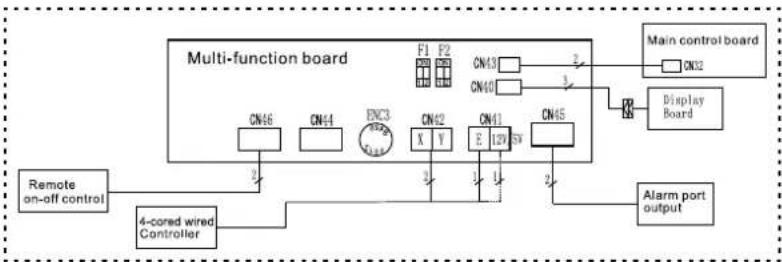
flowchart
graph TD
    A["Remote on-off control"] --> B["4-cored wired Controller"]
    B --> C["Multi-function board"]
    C --> D["Main control board"]
    D --> E["Display Board"]
    E --> F["CN12"]
    C --> G["F1 F2"]
    C --> H["X Y"]
    C --> I["E 129 S7"]
    C --> J["CN45"]
    C --> K["F13"]
    C --> L["F40"]
    C --> M["CN46"]
    C --> N["CN41"]
    C --> O["ENC3"]
    C --> P["X Y"]
    C --> Q["CN42"]
    C --> R["CN45"]
    C --> S["CN46"]
    C --> T["CN41"]
    C --> U["CN45"]
    C --> V["CN46"]
    C --> W["F13"]
    C --> X["F40"]
    C --> Y["F13"]
    C --> Z["F40"]
When connecting to 4-core wired controller:
$$ 1 2 \mathrm{V} = \text { R e d } $$
$$ E = \text { Black } $$
$$ Y = \text { Y e l l o w } $$
$$ X = \text { Brown } $$
- Cut the terminal of the longer connection cable (See Fig 3.3.2).
- Connect the four wires to each of the pins in the multi function board as follows: The red wire on wire controller connect to 12/5V pin on multi function board; black wire to E pin; yellow wire to Y pin; brown wire to X pin. (See Fig.3.3.1).
Fig 3.3.2

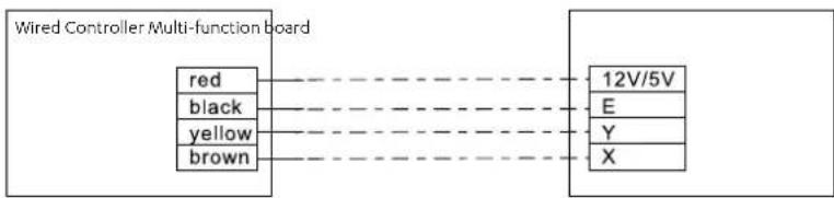
flowchart
graph LR
    A["Red"] --> B["12V/5V"]
    C["black"] --> B
    D["yellow"] --> B
    E["brown"] --> B
    B --> F["E"]
    B --> G["Y"]
    B --> H["X"]
3. Installation Method
e Controller
4. Wire controller - Removing the upper part
- Insert a flat screwdriver into the slots in the lower part of the wire controller (2 places).
- Remove the upper part of the wire controller (Fig.3.4)

Fig 3.4
NOTE
The PCB is mounted in the upper part of the wired controller. Be careful not to damage the board with the screwdriver.
5. Fasten the wire controller back plate
- For surface mounting, fasten the back plate on the wall with the 3 screws (M4x20) and plugs. (Fig.3.5)
Fig 3.5

NOTE
Place on a flat surface. Be careful not to distort the wire controller's back plate by over-tightening the mounting screws.
3. Installation Method
e Controller
6. Battery installation

natural_image
Diagram of a device casing with a plus symbol and arrow, no text or labels presentFig 3.7
- Place the battery in the unit and ensure the positive side of the battery is in accordance with the polarity markings. (See Fig.3.7)
- Set the correct time before operating. Batteries in the wired controller can maintain the correct time during a power failure. When the power is restored and the displayed time is not correct, replace the battery.
7. Wiring the indoor unit
There are three methods:
- from the rear;
- from the bottom;
- from the top;
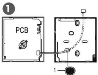


- Notch the part for the wiring to pass through with a nipper tool.
NOTE
DO NOT allow water to enter the remote control. Use a water loop and silastic to seal the wires.

Fig 3.8
3. Installation Method
e Controller
8. Reattach the wire controller's upper part
- While adjusting and mounting the upper case, avoid clamping the wiring during installation. (Fig 3.9)
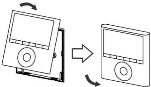
flowchart
graph TD
    A["Device with disk"] -->|Rotation Arrow| B["Device with disk"]
    B -->|Rotation Arrow| A
IMPORTANT: All the pictures in this manual are for illustration purposes only.
Your wire controller may differ slightly.
Fig 3.9
4. Specification
roller
Wiring Specifications
| Input Voltage | DC 12V |
| Ambient Temperature | 5°C~43°C |
| Ambient Humidity | RH40%~RH90% |
Wiring Specifications
| Wiring Type Size Total Length | ||
| Shielded PVC or cable | 0.75mm2 | ≤ 20m |
| 1.5mm2 | ≤ 50m | |
5. Feature and Function
te Controller
Feature and Function of the Wired Controller

Feature:
- LCD display.
- Malfunction code display: displays the error code (helpful for servicing)
• 4-way wire layout design.
• Room temperature display. - Weekly Timer
Function:
• Mode: choose Auto-Cool-Dry-Heat-Fan
• Fan speed: Auto-Low-Med-High
• Swing (on Wall Split and Cassettes)
- Timer ON/OFF
- Temp setting
• Weekly Timer
- Follow me
- Child Lock
- LCD Display
- Clock
• Elevating Panel Function (on Cassettes only)
6. Display
Wired Controller Display

- Operation mode indicator
- Fan speed indicator
- Left-right swing indicator
- Up-down swing indicator
- Elevating Panel Function indicator
- Main unit and secondary unit indicator
-
Follow me function indicator
-
Turbo/Auxiliary Heat function indicator
- °C indicator
- Temperature display
- Lock indicator
- Room temperature indicator
- Clock display
- On/Offtimer
- Timer display
7. Buttons
Wired Controller Buttons
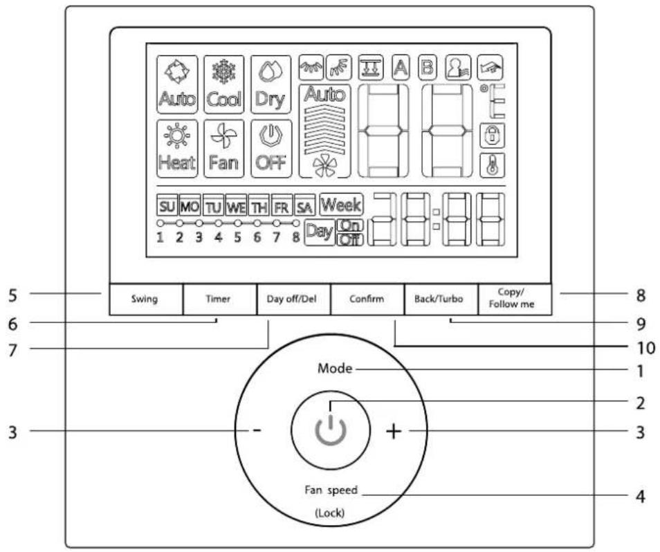
- Mode
- Power
- Adjust
- Fan Speed
-
Swing
-
Timer
- Day Off/Del
- Copy/Follow me
- Back/Turbo
- Confirm
8. Preparatory Operation
note Controller
Set the current Day and Time
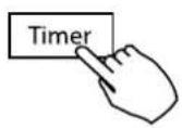
- Press TIMER for 3s or more. The timer displays flashes.
- Press + or - to set the date. The selected date flashes.


- Date setting is complete and the time setting is ready after pressing TIMER or if nothing is pressed in 10 seconds.

- Press + or - to set the current time. Press repeatedly to adjust the current time in 1 minute increments. Press and hold to adjust the current time.

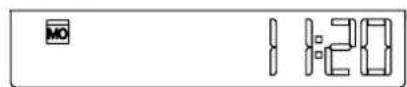
ex.Monday AM 11:20
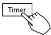
- The setting is complete after pressing TIMER or if no button is pressed for 10 seconds.
9. Operation
er
To Start/Stop Operation
Press the Power Button

To Set The Operation Mode (operating mode setting)
Press MODE to set the operation mode.


flowchart
graph LR
    A["Auto"] --> B["Cool"]
    B --> C["Dry"]
    C --> D["Heat"]
    D --> E["Fan"]
Room Temperature Setting
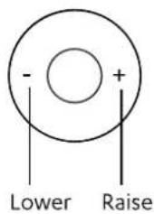
Press + or - to set the room temperature.
Indoor Setting Temperature Range: (17\~30°C).
9. Operation
er
Fan Speed Setting
Press FAN SPEED to set the fan speed.
NOTE: This function is unavailable in the AUTO or DRY modes
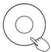
Fan speed (Lock)

flowchart
graph LR
    A["Auto"] --> B["Stage 1"]
    B --> C["Stage 2"]
    C --> D["Stage 3"]
    D --> E["Stage 4"]
Room Temperature Sensor Selection
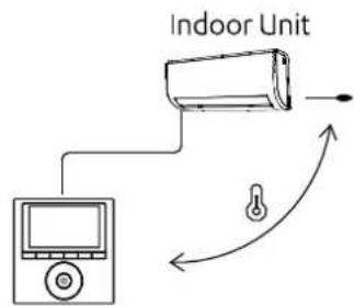
Press FOLLOW ME to select whether the room temperature is detected at the indoor unit or at the wired controller.
NOTE: When the FOLLOW ME function indication 📁 appears, the room temperature is detected at the wire remote controller.


Child Lock Function
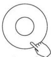
Press LOCK for 3 seconds to activate the CHILD LOCK feature and lock all buttons on the wired controller. Press again for 3 seconds to deactivate.
NOTE: When the child lock function is activated, the lock image 🔒 appears.
Fan speed (Lock)
9. Operation
er
Keypad Tone Setting
Press SWING and TIMER simultaneously for 3 seconds to disable the keypad tone. Press the buttons again for 3 seconds to enable the keypad tone.

Turbo
- Press TURBO to activate/deactivate the Turbo function.
The turbo function sets the unit to reach the user's present temperature in the shortest amount of time possible. - When the user presses TURBO, the unit sets to the highest fan speed setting to jump-start the cooling / heating process.

Elevating Panel Function (only for Cassette models)
-
When the unit is off Press the MODE button long to activate the lift panel function. The 📄 mark will flash.
-
Press the button + and - to control the lift and drop of the panel.
Pressing the + button can stop the panel, while it is dropping.
Pressing the - button can stop the panel, while it is lifting.


Swing Function (for Cassette models)
Up-Down airflow direction and swing

- Use SWING to adjust the up and down airflow direction
-
Every time the user presses SWING, the louvre swings six degrees.
-
Press and hold SWING for 2 seconds, it changes to the UP-DOWN SWING mode. Press SWING again to stop. When the Up-Down swing function is activated, the mark appears. (Not applicable to all the models)
- The operation can refer to the following instructions for the unit with four Up-Down louvres can be operated individually.
- Press the SWING button to activate the Up-Down adjusting louvre function.
The 📂 mark will flash. (Not applicable to all the models)
- Pressing the button "+" or "-" can select the movement of four louvres.
Each time you push the button, the wire controller select in a sequence that goes from: (the -0 icon means the four louvres move at the same time.)

flowchart
graph LR
    A["-0"] --> B["-1"]
    B --> C["-2"]
    C --> D["-3"]
    D --> E["-4"]
    E --> F["End"]
- And then use SWING button to adjust the Up-Down airflow direction of the selected louvre.
9. Operation
er
Swing Function (for Wall Split models)
1. Up-Down swing
Press the Swing button to start up-down swing function.
Press it again to stop.
When the Up-Down swing function is activated, the mask appears.
2. Left-Right swing
Press the Swing button long to start Left-Right swing function.
Press it again to stop.
When the Left-Right swing function is activated, the mark appears.

10. Timer Functions
ontroller
Timer Overview
Weekly Timer
Use to set the operating times for each day of the week.
On Timer
Use to start the air conditioner operation.
The timer operates and the air conditioner operation starts after the time has passed.
Off Timer
Use to stop the air conditioner operation.
The timer operates and the air conditioner operation stops after the time has passed.
On and Off Timer
Use to start and stop the air conditioner operation.
The timer operates and the air conditioner operation starts and stops after the time has passed.
10. Timer Functions
ontroller
To Set the On or Off Timer
- Press Timer to select the Day On or Day button.

flowchart
graph LR
    A["Timer"] --> B["No display"]
    B --> C["Week"]
    C --> D["Day On"]
    D --> E["Day Off"]
    E --> F["Day On/Off"]
- Press Confirm and the Clock display flashes.

- Press + or - to set the time. After the time is set, the timer starts or stops automatically.


ex.Off timer set at PM 6:00
- Press Confirm again to finish the settings.
10. Timer Functions
ontroller
To Set the On and Off Timer
- Press Timer to select the On button.
- Press Confirm and the Clock display flashes.

- Press the button + or - to set the On Timer and then press Confirm.


- Press the button + or - to set the Off Timer.

- Press Confirm to finish the setting.
11. Weekly Timer
troller
1. Weekly Timer Setting
Press Timer to select the Week and press confirm.


2. Day Of The Week Setting
Press the button + or - to select the day of the week and then press Confirm.


flowchart
graph LR
    A["SU"] --> B["MO"]
    B --> C["TU"]
    C --> D["WE"]
    D --> E["TH"]
    E --> F["FR"]
    F --> G["SA"]
3. Event timer setting
Press the button + or - to select the setting time.
The setting time, mode, temperature and fan speed appear on the LCD.
Press Confirm to enter the setting time process.
11. Weekly Timer
troller
IMPORTANT
Up to 8 scheduled events can be set on one day. Various events can be scheduled in either MODE, TEMPERATURE and FAN speeds.

flowchart
graph LR
    A["1"] --> B["TU"]
    B --> C["Week"]
    style A fill:#f9f,stroke:#333
    style B fill:#ccf,stroke:#333
    style C fill:#cfc,stroke:#333
ex.Tuesday time scale 1
4. Timer Setting
Press + and - to set the time then press Confirm.

NOTE: To set the off time event refer to step 8.
5. Operation Mode Setting
Press + and - to set the operation mode then press Confirm.



flowchart
graph LR
    A["Auto"] --> B["Cool"]
    B --> C["Dry"]
    C --> D["Heat"]
    D --> E["Fan"]
    E --> F["OFF"]
6. Room Temperature Setting
Press + and - to set the room temperature then press Confirm.
NOTE: This setting is unavailable in the FAN or OFF modes.

11. Weekly Timer
troller
7. Fan Speed Setting
Press + and - to set the fan speed then press Confirm.


NOTE: This setting is unavailable in the AUTO, DRY or OFF modes.

flowchart
graph LR
    A["Auto"] --> B["Step 1"]
    B --> C["Step 2"]
    C --> D["Step 3"]
    D --> E["Final Output"]
8. Off Mode Setting
Press + and - to set the operation off then press Confirm.


flowchart
graph LR
    A["Auto"] --> B["Cool"]
    B --> C["Dry"]
    C --> D["Heat"]
    D --> E["Fan"]
    E --> F["Off"]
9. Different Scheduled Events
Different scheduled events can be set by repeating steps 3 through 7.
10. Additional Days
Additional days, in a one week period, can be set by repeating steps 3 through 8.
NOTE: The weekly timer setting can be returned to the previous step by pressing BACK. The current setting is restored. The controller will not save the weekly timer settings if there is no operation within 30 seconds.
11. Weekly Timer
troller
To Start
Press Timer to select the Week, and then the timer starts automatically.


ex.
To Cancel
Press Power to cancel the timer mode.

The timer mode can also be cancelled by changing the timer mode using Timer.

To Set The Day Off (for a holiday)
- After setting the weekly timer, press Confirm.
- Press + or - to select the day of the week.
11. Weekly Timer
troller
To Create An Off Day
- Press DAY OFF to create an off day.


flowchart
graph TD
    A["The WE mark is hidden"] --> B["1 2 3 4"]
    B --> C["→"]
    C --> D["1 2 3 4"]
    D --> E["Su MO TU TH FR SA Week"]
ex.The DAY OFF is set for Wednesday
- Set the DAY OFF for other days by repeating the steps 2 and 3.
- Press BACK to revert to the weekly timer.
To Create An Off Day
• To cancel, follow the same procedures used for setup
NOTE: The DAY OFF setting is cancelled automatically after the set day has passed.
To Copy Out The Setting
Copy out the setting in one day into the other day.
- A scheduled event, made once, can be copied to another day of the week. The scheduled events of the selected day of the week will be copied. The effective use of the copy mode ensures the ease of reservation making.
- In the weekly timer, press Confirm.

- Press + or - to select the day to copy from.

11. Weekly Timer
troller
To Copy Out The Setting (continued)
- Press COPY, the letters CY appear on the LCD.
- Press + or - to select the day to copy to.

- Press + or - to select the day to copy to.
- Press COPY to confirm.
The WE mark flashes quickly

ex. Copy the setting of Monday to Wednesday
- Other days can be copied by repeating steps 4 and 5
- Press Confirm to confirm the settings.
- Press BACK to revert to the weekly timer
11. Weekly Timer
troller
Delete The Time Scale In One Day
To Delete the time scale in one day.
- During the weekly timer setting, press Confirm.

- Press + and - to select the day of the week and then press Confirm.

- Press + and - to select the setting time want to delete.
The setting time, mode, temperature and fan speed appear on the LCD.
The setting time, mode, temperature and fan speed can be deleted by pressing the DEL (day off).


flowchart
graph LR
    A["Start"] --> B["Step 1"]
    B --> C["Step 2"]
    C --> D["Step 3"]
    D --> E["Step 4"]
    E --> F["Week 1"]
    F --> G["Output Box"]
    style A fill:#f9f,stroke:#333
    style G fill:#bbf,stroke:#333
ex. Delete the time scale 1 in Saturday
12. Fault Alarm Handling
bte Controller
Error Codes
| Error Codes | Causes |
| E0 | Phase sequence error or phase malfunction |
| E1 | Communication malfunction between indoor and outdoor units |
| E2 | T1 sensor malfunction |
| E3 | T2A sensor malfunction |
| E4 | T2B sensor malfunction |
| E5 | T3 or T3 or TP sensor malfunction |
| E6 | Zero check malfunction |
| E7 | Indoor EERROM malfunction |
| E8 | Fan controller out of control |
| E9 | Communication malfunction between main PCB and display board |
| EA | Compressor overload (4 times) |
| EB | IPM mould malfunction |
| EC | Air clean malfunction |
| ED | Outdoor malfunction protection |
| EE | Full-water malfunction |
| EF | Other fault |
| P0 | Evaporator temperature protection |
| P1 | Enter anti-code or defrost mode |
| P2 | Condenser temperature protection |
| P3 | Compressor temperature protection |
Please check the indoor unit's error display and review the owner's manual if other error codes appear.
12. Fault Alarm Handling
ote Controller
Error Codes
| Error Codes | Causes |
| P4 | Discharge pipe temperature protection |
| P5 | Discharge high pressure protection |
| P6 | Discharge low pressure protection |
| P7 | Over-voltage protection |
| P8 | Compressor overload protection |
| P9 | Reserve code |
| PA | Reserve code |
| PB | Reserve code |
| PC | Reserve code |
| PD | Reserve code |
| PE | Reserve code |
| PF | Other fault |
Please check the indoor unit's error display and review the owner's manual if other error codes appear.

ActronAir
That's better. That's Action.
actronair.com.au
1300 522 722
- INSTALLATION & OWNER'S MANUAL
- IMPORTANT NOTE:
- Table of Contents
- Installation and Owner's Manual
- Safety Precautions
- Controller
- WARNING
- WARNINGS FOR PRODUCT USE
- Read Safety Precautions Before Installation
- Installation Components
- Remote Controller
- Precaution for the installation of the wired controller
- Installation Method
- e Controller
- Wired remote controller dimensions
- Wiring Connection Diagram for Cassettes & Ducted
- Wiring Connection For Wall Splits
- Wire controller - Removing the upper part
- NOTE
- Fasten the wire controller back plate
- Battery installation
- Wiring the indoor unit
- There are three methods:
- Reattach the wire controller's upper part
- Specification
- roller
- Feature and Function
- te Controller
- Feature:
- Function:
- Display
- Buttons
- Preparatory Operation
- note Controller
- Set the current Day and Time
- Operation
- To Start/Stop Operation
- To Set The Operation Mode (operating mode setting)
- Room Temperature Setting
- Fan Speed Setting
- Room Temperature Sensor Selection
- Child Lock Function
- Keypad Tone Setting
- Turbo
- Elevating Panel Function (only for Cassette models)
- Swing Function (for Cassette models)
- Up-Down airflow direction and swing
- Swing Function (for Wall Split models)
- Up-Down swing
- Left-Right swing
- Timer Functions
- ontroller
- Timer Overview
- Weekly Timer
- On Timer
- Off Timer
- On and Off Timer
- To Set the On or Off Timer
- To Set the On and Off Timer
- Weekly Timer
- troller
- Weekly Timer Setting
- Day Of The Week Setting
- Event timer setting
- IMPORTANT
- Timer Setting
- Operation Mode Setting
- Room Temperature Setting
- Fan Speed Setting
- Off Mode Setting
- Different Scheduled Events
- Additional Days
- To Start
- To Cancel
- To Set The Day Off (for a holiday)
- To Create An Off Day
- To Copy Out The Setting
- To Copy Out The Setting (continued)
- Delete The Time Scale In One Day
- Fault Alarm Handling
- bte Controller
- ote Controller
- ActronAir
Brand : ActronAir
Model : URC-125CS
Category : Air Conditioning