
CRV240T - Air Conditioning ActronAir - Free user manual and instructions
Find the device manual for free CRV240T ActronAir in PDF.


| Product Type | Split Ducted Outdoor Unit (Advance Series) |
| Brand | ActronAir |
| Model | CRV240T |
| Dimensions (L x W x H) | 1685 x 685 x 1105 mm |
| Weight | 209 kg |
| Power Supply | 230/400V, 3-Phase, 50Hz |
| Refrigerant Type | R-410A |
| Factory Refrigerant Charge | 9350 g |
| Pre-charged Pipe Length | 15 m |
| Max. Equivalent Pipe Length | 60 m |
| Max. Vertical Height Difference | 20 m |
| Liquid Line Pipe Size | 1/2 inch (12.7 mm) |
| Gas Line Pipe Size | 7/8 inch (22.2 mm) |
| Compressor Type | Inverter Scroll Compressor |
| Indoor Fan Type | EC (Electronically Commutated) Fan |
| Outdoor Fan Type | Axial Fans with Direct Drive AC Motor |
| Expansion Valve | Electronic Expansion Valve (EEV) |
| Coil Protection | Hydrophilic Coated with Blue Coat Protection |
| Control Options | Wall Controllers (NEO, LR7-1, LC7-2), BMS, Third Party |
| Demand Response | AS/NZS 4755.3.1 compliant |
| Safety Features | High/Low Pressure Controls, Crankcase Heater (for pipes >8m) |
| Installation Requirements | Licensed HVAC technician, proper clearances, electrical isolation |
| Maintenance Frequency | Annually for residential; quarterly for commercial |
Frequently Asked Questions - CRV240T ActronAir
User questions about CRV240T ActronAir
0 question about this device. Answer the ones you know or ask your own.
Ask a new question about this device
Download the instructions for your Air Conditioning in PDF format for free! Find your manual CRV240T - ActronAir and take your electronic device back in hand. On this page are published all the documents necessary for the use of your device. CRV240T by ActronAir.
USER MANUAL CRV240T ActronAir
ADVANCE Split Ducted Unit
Installation and Commissioning Guide - Outdoor

natural_image
Exterior view of a beige industrial air conditioning unit with two fans and a 'ActronAir' logo (no text-heavy elements)Model Numbers
CRV140S
CRV160S
CRV180S
CRV160T
CRV180T
CRV210T
CRV240T
IMPORTANT NOTE:
Please read this manual carefully before installing or operating your air conditioning unit.
That's better. That's Action.

Table of Contents
Introduction 4
General Information ....5
Safety Instructions ....7
Installation Information ....8
Operation Manual Access 9
Components Overview 10
Control Panel 11
Single Phase (CRV140-180S) 11
Three Phase (CRV160-240T) 11
Unit Dimensions and Clearances ......12
CRV140S 12
CRV160S / CRV160T / CRV180S / CRV180T 13
CRV210T / CRV240T 14
Unit Lifting Procedure 15
Outdoor Unit Preparation 17
Field Pipe Connection ....19
Piping and Brazing 19
Pressure Testing 22
Evacuation Procedure (Triple Evacuation) 22
Specifications for Refrigeration 24
Electrical Installation 26
Electrical Connection 27
Split Unit 27
Data Cable Shielding Instructions 28
Circuit Breaker Size and Cable Size Requirement 29
Wall Controller Options 30
Wall Controller Options 30
Wiring Configuration : Recommended 31
Wiring Connections 33
LR7-1 and LC7-2 Wall Control Wiring Connections 33
NEO Wall Control Wiring Connections 33
LM-RS-2 Optional Sensor Wiring Connections 34
AERSS Optional Duct Sensor Wiring Connections 34
Demand Response Management 35
Configuring and Commissioning Setup 36
Menu and Navigation 36
Configuring Compressor and Capacity(cnFg) 36
Configuring Control Source (CtrS) 36
Third Party Control Input (Indoor and/or Outdoor Board) 38
0-10V Analogue Input for Compressor and Indoor Fan 38
0-10V Analogue Input for Compressor with Fixed Indoor Fan Speed 39
Input for Fixed Compressor with Fixed Indoor Fan Speed 39
0-10V Analogue Input for Indoor Fan with Fixed Speed Compressor 40
Run and Fault Indication Output (Outdoor Board) 40
Remote On/Off 41
Installation and Commissioning Guide
Advance Outdoor Units
Indoor Fan Commissioning 42
EVV140S / EFV140S 42
EVV160S / EFV160S 45
Refrigerant Charging 57
Maintenance 61
Maintenance Frequency Checklist 63
Start Up and Commissioning Report 64
Installation and Commissioning Guide
Advance Outdoor Units
Introduction
CONGRATULATIONS on your purchase of an ActronAir air conditioning system! This unit has been designed and engineered to provide optimum air conditioning and to achieve maximum energy efficiency.
Your air conditioning system has been manufactured from the highest quality materials. Numerous "in house" and "external" inspection and test procedures were conducted to your air conditioner to ensure satisfactory operation.
Information About This Guide
This guide provides installation instructions, specific to your split ducted unit. Read this manual thoroughly and take into consideration all specifications and instructions to ensure correct installation and safe operation of your air conditioning system.
NOTE
Print a copy of this document and keep it for future reference. Ensure all technicians that work on the unit can refer to this manual at any time.
Product Inspections
Check your air conditioning unit and all items against the invoice upon receiving your shipment. Inspect the unit, components and accessories for any sign of damage. If there is any damage to the unit, contact ActronAir Customer Care Department immediately on: 1300 522 722 to obtain a Goods Return Number.
Check the unit nameplate to verify the model, serial number, electrical rated specifications are correct.
Codes, Regulations And Standards
The installer and/or contractor assumes responsibility to ensure that unit installation complies with the relevant council, state / federal codes, regulations and building code standards. All electrical wiring must be in accordance with current electrical authority regulations and all wiring connections to be as per electrical diagram provided with the unit
Installation and Commissioning Guide
Advance Outdoor Units
General Information
The ActronAir Advance Series Ducted air conditioning units are designed for applications where superior performance, high efficiency, reliability, supply air quality and quiet operation are the prime priorities. The units are built with the latest technology, inverter scroll compressor, EC indoor fans, low-noise outdoor fans and an intelligent electronic control.
For optimum efficiency, your air conditioning unit will deliver just the right amount of cooling or heating capacity you demand. Even in extreme conditions, the unit will still supply the required demand at peak performance.
Energy Efficient Refrigeration Circuits
The ActronAir system is designed with a split ducted refrigeration circuit that delivers only the amount of cooling or heating actually required to maintain your desired comfort at the most optimum efficiency.
Each refrigeration circuit consists of:
• High efficiency variable capacity scroll compressor with individual compressor drive.
- Hydrophilic coated condenser coil designed for optimum performance and efficiency with corrugated fins and riffled tubing.
- Hydrophilic coated evaporator coil designed for optimum performance and efficiency with lanced fins and riffled tubing.
• Electronic expansion valve (EEV), to maintain efficiency at different operating conditions.
Evaporator Section
The evaporator section has EC fans which deliver just the right amount of airflow, depending on requirements. The fans provide superior performance for your comfort at optimum efficiency:
• Highly efficient variable speed EC motor that uses less energy than the traditional air conditioner.
- Easy variable indoor fan commissioning via intelligent controllers.
- Low noise operation.
Condenser Section
Uses two (2) axial fans and a state of the art inverter scroll compressor, with the following features:
- Efficient Tru-Inverter Compressor and Inverter Drive combination.
- Efficient axial fans with direct drive AC motor.
- Low noise operation.
Electrical Section
The electrical section is composed of a separate panel for controls, protecting the components from the elements.
Durable Design and Construction
ActronAir is an Australian manufacturer with proven high quality air conditioning products. Known for their durability and reliable performance, these products are designed and built to withstand the extreme weather conditions.
The galvanized steel cabinet, with powder coated epoxy enamel finish, resists the toughest conditions. The louvered outdoor coil guard protects the condenser coil from any potential damage brought by hail, stones and other solid objects that may be projected to the unit.
Blue Coat Coil Protection heat exchangers ensures an enhanced heat transfer with increased performance efficiency.
System Flexibility
The ActronAir Advance series of air conditioning units are the first choice for residential, office, schools and other air conditioning facilities applications, both for new construction or retrofitting projects.
Refrigerant Handling and Accountability
ActronAir strongly urges that all service technicians make every effort to eliminate and/or vigorously reduce the emission of refrigerants to the atmosphere. Everyone must act in a responsible manner to conserve refrigerants.
Installation and Commissioning Guide
Advance Outdoor Units
Sustainability and Environmentally Friendly
The air conditioning system is supplied with zero ozone depleting R-410A refrigerant, which has no phase out or replacement concern.
With cooling and heating performance capacity that are among the best in the market, the ActronAir air conditioning units provide the solution for the reduction of energy consumption, CO_2 emission, high fuel dependency and high network grid demand.
Installation and Commissioning Guide
Advance Outdoor Units
Safety Instructions
- Only licensed HVAC technicians* should install and service air conditioning equipment. Improper service or alteration by an unqualified technician could result in significant and major damage to the product or property which may render your warranty null and void. Such unqualified service could also lead to severe physical injury or death. Follow all safety instructions in this literature and all warning labels that are attached to the equipment.
- Prevailing WH&S regulations must be observed and will take precedence to the safety instructions contained on this manual. Safe work practices and environment must be the paramount importance in the performance of all the service procedures.
- Ensure that unit installation complies with relevant council regulations and building code standards.
- All electrical wiring must be in accordance with current electrical authority regulations and all wiring connections to be as per electrical diagram provided.
- Secure the fans against accidental contact. Beware of pinch point and sharp edges which can cause cutting injury.
• Always wear appropriate PPE, remove any dangling jewelry and protect long hair by wearing a cap. - Make sure that safety guards and panel covers are always firmly secured and not damaged before and during operation of unit.
- This appliance is not intended for use by young children or infirm persons unless they have been adequately supervised by a responsible person to ensure that they can use the appliance safely. Young children should be supervised to ensure that they do not play with the appliance.
- Installer must incorporate a means of electrical disconnection (isolator) in the sub mains fixed wiring in accordance with the latest edition of the AS/NZS 3000 (also known as Australian Wiring Rules).
- Secure the power cords and control cables that goes in/out the unit. Use the cable ties provided in the control box.
*Qualifications required will be appropriate Electrical, Refrigeration and Refrigerant Handling License and Training dependent on local State/Territory regulations.

DANGER
Hazardous Voltage - Risk of Electrocution.
TURN-OFF the power from main isolator before proceeding with any service work of the unit. Observe proper LOCK-OUT/TAG-OUT (LOTO) procedures for electrical appliances in order to prevent accidental switching-on of the power supply.

WARNING
EC Motors and Compressor Drives are fitted with high power capacitors and can have dangerous residual voltages at motor/drive terminals after power has been isolated. Wait at least 5 minutes after power isolation and test for any residual voltage before beginning service work.

CAUTION
Beware of Rotating Fans!
Ensure that indoor and outdoor fans are isolated and have come to a complete stand still before servicing the equipment. Beware of pinch point and sharp edges which can cause cutting injury. Secure the fans against accidental contact. Always wear appropriate PPE and remove any dangling jewellery and protect long hair by wearing a cap. Ensure that no loose clothing can be caught / entangled in moving parts.
VISUAL INSPECTION AND WORK ASSESSMENT
Work areas and conditions must first be assessed and evaluated for any potential hazardous conditions. It is also important to be familiar with the unit parts and components before proceeding with any service task.
Installation and Commissioning Guide
Advance Outdoor Units
Installation Information
All service technicians handling refrigerant must be licensed to handle refrigerant gases.
Recover and Recycle Refrigerants
Never release refrigerant to the atmosphere! It is an offence in Australia to do so. Always recover, recycle and reuse refrigerants. When removing from the system, properly contain and identify refrigerants in its dedicated container for proper disposal and/or storage. Always consider the recycle or reclaim requirements of the refrigerant before beginning the recovery procedures. Obtain a chemical analysis of the refrigerant if necessary. For the recovered refrigerant and acceptable refrigerant quality, refer to the existing standards and regulations.
Refrigerant Handling and Safety
Consult the refrigerant manufacturer's Material Safety Data Sheet (MSDS) for information on proper handling and to fully understand health, safety, storage and disposal requirements. Use the approved containment vessels and refer to appropriate safety standards. Comply with all applicable transportation standards when shipping refrigerant containers.
Service Equipment and Recovery Procedures
Always use refrigerant reclaiming equipment in order to minimise refrigerant emissions. Use equipment and methods which will pull the lowest possible system vacuum while recovering and condensing refrigerant. Equipment capable of pulling a vacuum of less than 500 microns is required.
Do not open the system to the atmosphere for service work until refrigerant is fully removed and/or recovered. Perform refrigeration system evacuation, prior to charging, in accordance with AIRAH / IRHACE Refrigerant handling code of practice.
Let the unit stand for 1 hour and with the vacuum not rising above 500 microns. A rise above 500 microns indicates a leak from the system and a leak test is required to locate and repair any leak.

CAUTION
A leak test is always required on any repaired section of the refrigeration system.
Charge refrigerant into the system only after the equipment does not leak or contain moisture. Take into consideration the correct amount of refrigerant charge specified for the system to ensure efficient unit operations. When charging is complete, reclaim refrigerant from charging lines into an approved refrigerant container. Seal all used refrigerant containers with approved closure devices to prevent unused refrigerant from escaping to the atmosphere. Take extra care to maintain all service equipment directly supporting refrigerant service work such as gauges, hoses, vacuum pumps and recycling equipment.
INSTALLATION PREPARATION (Pre-Installation considerations)
The following items must be considered before beginning the unit installation:
- Verify the unit capacities and ratings with the unit nameplate.
- Make certain the floor or foundation is level, solid and has sufficient structural strength to support the unit and accessories weight.
- Allow minimum recommended clearances for periodic maintenance and service access.
- Allow sufficient space above the unit for the outdoor air discharge. Condenser air inlet, located on the coil side of the unit, requires sufficient airflow clearance for the optimum unit performance.
- Note the conditioned supply air and return air location. Ensure sufficient spaces are allocated for these purposes.
- For the connection and location of condensate drain in the unit, refer to the drawings and dimensions section of this manual.
- Wiring connections must be in accordance with the wiring diagram provided with the unit.
• Make sure all wirings are in accordance with local electricity authority regulations and standards. - Do not install the unit close to an area where there is a danger of fire due to volatile, explosive, flammable and/or hazardous materials.
Installation and Commissioning Guide
Advance Outdoor Units
- Ensure that spaces around the unit are free from any obstructions for optimum unit performance.
- Installer to ensure correct size/type that main circuit breaker and cable is installed in unit sub-mains to protect the sub-mains and unit wiring.
- Installer to ensure correctly rated residual current device (RCD) is installed as per the latest edition of the AS/NZS 3000 (also known as Australian Wiring Rules).
- Secure the power cords and control cables that goes in/out the unit. Use the cable ties provided in the control box.

CAUTION
This outdoor unit is designed to match only with an ActronAir indoor unit as specified in the Technical Selection Catalogue. The unit is supplied with factory charged refrigerant as stated in the Rating Label. The use other material as a refrigerant may cause explosion and/or personal injury.
Be aware of all the relevant regulations concerning the handling of refrigerant.
For units charged with R-410A
Ensure that R-410A is only charged in liquid form.
For units charged with R-32
R-32 refrigerant (CLASS A2L) is mildly flammable.
Thoroughly read and understand the accompanying R-32 Safety Guide for installation and maintenance instructions. Installation, service, maintenance, repairs and decommissioning of this unit must be performed by a licensed HVAC technician; qualified to handle R-32 refrigerant.
Appliance shall be installed, operated and stored in a well ventilated area:
- where the room size corresponds to the room area as specific for operation.
- without continuously operating open flames (for example an operating gas appliance) and ignition sources (for example an operating electric heater).
- away from other potential continuously operating sources that known to cause ignition of R-32 refrigerant.
R-32 refrigerant is odorless if the refrigerant gas comes into contact with fire, it may emit a poisonous gas.
Operation Manual Access
Download from website
Operation manuals can be downloaded through our website shown below.
https://www.actronair.com.au/brochures-manuals/#operating-manuals
Installation and Commissioning Guide
Advance Outdoor Units
Components Overview

Installation and Commissioning Guide
Advance Outdoor Units
Control Panel
Single Phase (CRV140-180S)

Three Phase (CRV160-240T)
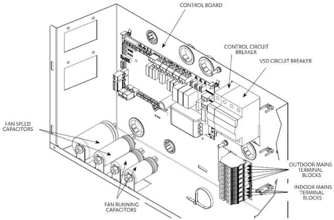
Installation and Commissioning Guide
Advance Outdoor Units
Unit Dimensions and Clearances
CRV140S
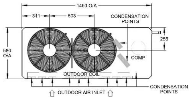
TOP VIEW
CONDENSATION POINTS ARE DESIGNED TO ENSURE ALL CONDENSATION IS REMOVED EFFICIENTLY TO AVOID WATER POOLING WITHIN THE CONDENSER. IF A SINGLE CONDENSATION DRAIN POINT IS REQUIRED, ACTRONAIR RECOMMENDS THE INSTALLATION OF A CONDENSER TRAY. THESE ARE AVAILABLE AS AN ADDITIONAL ACCESSORY.
** DRAWING IS SUBJECT TO CHANGE WITHOUT NOTICE**
SIDE VIEW
FRONT VIEW
| UNIT MODEL NUMBER | UNIT WEIGHT (kg) | CORNER WEIGHTS (kg) | |||
| A | B | C | D | ||
| CRV140S 131 | 21 34 | 28 | 48 | ||
MINIMUM SERVICE ACCESS AREAS AND AIRFLOW CLEARANCES

NOTES:
- Do not scale drawing. All dimensions are in mm unless specified. Refer to corresponding unit dimensional drawing for mounting hole details.
- Service Access Areas and Spaces for Airflow Clearances given are suggested minimum based on the condition that the spaces around the units are free from any obstructions and a walkway passage of 1000mm between the units or between the unit and the outside perimeter is available.
- Minimum service access areas and spaces for airflow clearances are responsibilities of the installer, ActronAir will not be held liable for any extra charges incurred due to lack of access and space for airflow.
- Under all circumstances, condenser air must not recirculate back onto condenser coil. Keep all clearance free of any obstructions.
- Maximum External Static of Outdoor Fans is 5 Pa.
- STACKING OF UNITS: Ensure that minimum airflow and clearances are met.
- Refer to pipe Connection Details on Specifications Sheet.
- MTG C-C DIST = Mounting Centre to Centre Distance.
- Use M12 bolt for feet mounting.
Installation and Commissioning Guide
Advance Outdoor Units
CRV160S / CRV160T / CRV180S / CRV180T

CONDENSATION POINTS ARE DESIGNED TO ENSURE ALL CONDENSATION IS REMOVED EFFICIENTLY TO AVOID WATER POOLING WITHIN THE CONDENSER. IF A SINGLE CONDENSATION DRAIN POINT IS REQUIRED, ACTRONAIR RECOMMENDS THE INSTALLATION OF A CONDENSER TRAY. THESE ARE AVAILABLE AS AN ADDITIONAL ACCESSORY.
** DRAWING IS SUBJECT TO CHANGE WITHOUT NOTICE**

SIDE VIEW

FRONT VIEW
| UNIT MODEL NUMBER | UNIT WEIGHT (kg) | CORNER WEIGHTS (kg) | |||
| A | B C D | ||||
| CRV160S 144 | 22 36 34 52 | ||||
| CRV160T 150 | 22 41 34 53 | ||||
| CRV180S 152 | 22 43 34 53 | ||||
| CRV180T 155 | 23 44 35 53 | ||||
MINIMUM SERVICE ACCESS AREAS AND AIRFLOW CLEARANCES

NOTES:
- Do not scale drawing. All dimensions are in mm unless specified. Refer to corresponding unit dimensional drawing for mounting hole details.
- Service Access Areas and Spaces for Airflow Clearances given are suggested minimum based on the condition that the spaces around the units are free from any obstructions and a walkway passage of 1000mm between the units or between the unit and the outside perimeter is available.
- Minimum service access areas and spaces for airflow clearances are responsibilities of the installer, ActronAir will not be held liable for any extra charges incurred due to lack of access and space for airflow.
- Under all circumstances, condenser air must not recirculate back onto condenser coil. Keep all clearance free of any obstructions.
- Maximum External Static of Outdoor Fans is 5 Pa.
- STACKING OF UNITS: Ensure that minimum airflow and clearances are met.
- Refer to pipe Connection Details on Specifications Sheet.
- MTG C-C DIST = Mounting Centre to Centre Distance.
- Use M12 bolt for feet mounting.

Installation and Commissioning Guide
Advance Outdoor Units
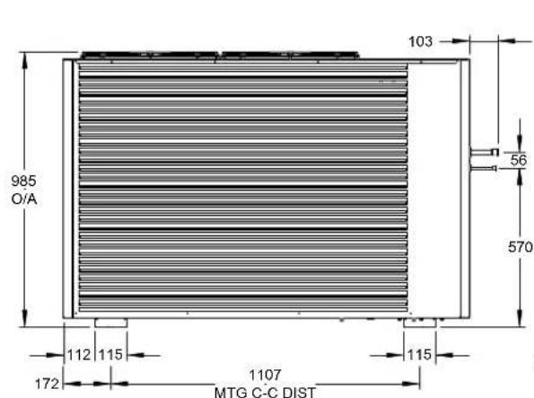
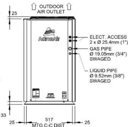
CRV210T / CRV240T
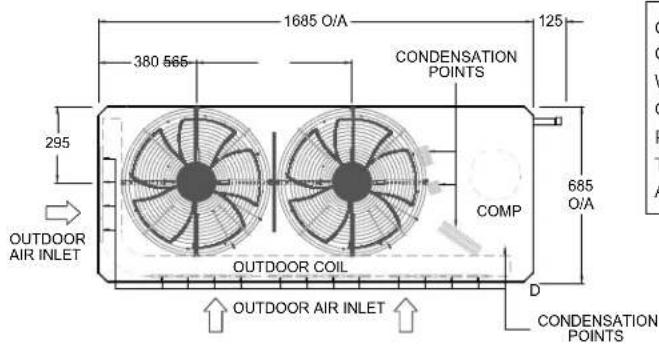
CONDENSATION POINTS ARE DESIGNED TO ENSURE ALL CONDENSATION IS REMOVED EFFICIENTLY TO AVOID WATER POOLING WITHIN THE CONDENSER. IF A SINGLE CONDENSATION DRAIN POINT IS REQUIRED, ACTRONAIR RECOMMENDS THE INSTALLATION OF A CONDENSER TRAY. THESE ARE AVAILABLE AS AN ADDITIONAL ACCESSORY.
** DRAWING IS SUBJECT TO CHANGE WITHOUT NOTICE**
TOP VIEW
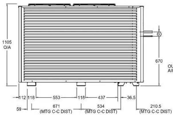

SIDE VIEW
| UNIT MODEL NUMBER | UNIT WEIGHT (kg) | CORNER WEIGHTS (kg) | |||
| A | B | C | D | ||
| CRV210T 200 | 27 53 | 48 72 | |||
| CRV240T 209 | 28 56 | 51 74 | |||
FRONT VIEW
MINIMUM SERVICE ACCESS AREAS AND AIRFLOW CLEARANCES

NOTES:
- Do not scale drawing. All dimensions are in mm unless specified. Refer to corresponding unit dimensional drawing for mounting hole details.
- Service Access Areas and Spaces for Airflow Clearances given are suggested minimum based on the condition that the spaces around the units are free from any obstructions and a walkway passage of 1000mm between the units or between the unit and the outside perimeter is available.
- Minimum service access areas and spaces for airflow clearances are responsibilities of the installer, ActronAir will not be held liable for any extra charges incurred due to lack of access and space for airflow.
- Under all circumstances, condenser air must not recirculate back onto condenser coil. Keep all clearance free of any obstructions.
- Maximum External Static of Outdoor Fans is 5 Pa.
- STACKING OF UNITS: Ensure that minimum airflow and clearances are met.
- Refer to pipe Connection Details on Specifications Sheet.
- MTG C-C DIST = Mounting Centre to Centre Distance.
- Use M12 bolt for feet mounting.

Installation and Commissioning Guide
Advance Outdoor Units
Unit Lifting Procedure

WARNING
WH&S regulations must be observed and will take precedence during lifting process.
NOTE
All drawings are for illustration purposes only. Actual unit may vary depending on the model.
Crane Lifting Method
Crane lifting method is recommended for high rise lifting.
Provide rubber pads under spreader bar to prevent damage to the unit

Connect the loop ends of slings into shackle
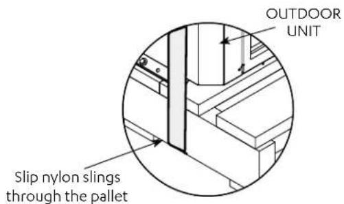
Fig. 1
DETAILA
Equipment Required For Crane Lifting:
• 1 Shackle
- 2 x Nylon Slings
- Spreader bars
Refer to catalogue for unit weight before selecting shackles and slings.
NOTE
Refer to Unit Dimensions and Clearances section for unit weight before selecting shackle and slings.
Procedure:
- Slip nylon slings through the pallet as shown in Fig. 1.
- Use a Bow or Dee shackle to connect the slings.
- Ensure slings are protected by rubber pads or similar if slings are draped across unit edges, corners, or air grilles. This will prevent the unit from being damaged during lifting.
Installation and Commissioning Guide
Advance Outdoor Units
- SPREADER BARS must be used when lifting the unit.
- Test lift the unit to determine exact unit balance and stability before hoisting it to the installation location.
Fork Lift Method

DANGER
Make sure rigging equipment, accessories and plant are sufficiently and safely capable to lift the unit in order to prevent potential damage to property, severe personal injury or death. Please check unit weight and weight distribution points as shown in the unit drawing dimensions section.
Procedure:
- To move the unit around with a forklift, insert the fork tines through the pallet, as shown in Fig. 2.
- Only fork the unit through compressor end or side of the unit. (See illustration for location of compressor end)

FIG.2

CAUTION
Length of fork lift tines must pass the unit middle section, in order to safely carry the unit.
Installation and Commissioning Guide
Advance Outdoor Units
Outdoor Unit Preparation
- Remove mounting screws.
- Remove Access Panel-Electrical as illustrated below.


- Remove the Shipping Blocks.
a. Loosen the set bolts that hold the compressors down onto the unit (3 pcs).

Installation and Commissioning Guide
Advance Outdoor Units
b. Remove Shipping blocks as shown below.

c. Tighten back the set bolts that hold the compressors down onto the unit (3 pcs).

- Install Interconnecting Field Pipes. Braze refrigeration piping.

natural_image
Technical line drawing of an industrial machine with internal components and ventilation ducts (no text or labels)
WARNING
Live electrical within enclosure. Isolate electrical supply before removing panels. Authorised technicians access only.
Installation and Commissioning Guide
Advance Outdoor Units
Field Pipe Connection
Piping and Brazing

CAUTION
This outdoor unit described in this guide is designed to match only with an ActronAir indoor unit as specified in the Technical Selection Catalogue.
- The unit is supplied with factory charged refrigerant as stated in the Rating Label. The use of other material as a refrigerant may cause explosion and/or personal injury.
- Be aware of all the relevant regulations concerning the handling of refrigerant.
- The system of this unit operates with Polyester (POE) ^* oil.
- The maximum time any system can be opened to atmosphere is 15 minutes.
- It is important to work with absolute cleanliness.
- Secure Hot Work Permit as required.
- Brazing must be done with the use of Nitrogen to avoid carbon deposits into the pipes.
• The system must be evacuated thoroughly to 500 microns (see evacuation procedure). - Never allow refrigerant to vent into the atmosphere. It is an offence to release refrigerant in Australia.
• Always reclaim refrigerant using equipment and container dedicated for the refrigerant used in the system. - Only qualified technicians are allowed to perform any work described in this guide and all work must be carried out in accordance with Australia and New Zealand refrigerant handling code of practice.
*CRQ Single Phase models use Polyvinylether (PVE) oil.
Maximum allowable total equivalent field pipe length is 60 metres, see diagram on the next page. This includes all the equivalent pipe fitting loses and vertical height difference. Vertical height difference must not exceed 20 metres. Table below shows the equivalent straight pipe length of elbow fittings.
| TABLE : EQUIVALENT STRAIGHT PIPE LENGTH OF ELBOW FITTINGS (METRES) | ||||
| Pipe size Nominal Diameter | 90° Long Radius Elbow | 90° Short Radius Elbow | 45° Long Radius Elbow | 45° Short Radius Elbow |
| 9.52 (3/8") | 0.24 0.36 0.09 | 0.14 | ||
| 12.7 (1/2") | 0.27 0.41 0.12 | 0.19 | ||
| 15.88 (5/8") | 0.30 0.45 0.15 | 0.23 | ||
| 19.05 (3/4") | 0.40 0.60 0.18 | 0.27 | ||
| 22.22 (7/8") | 0.46 0.69 0.21 | 0.32 | ||
| 25.4 (1") | 0.52 0.78 0.24 | 0.36 | ||
| 28.58 (1-1/8") | 0.55 0.83 0.27 | 0.41 | ||
Installation and Commissioning Guide
Advance Outdoor Units
Selected field pipe sizes must match the recommended sizes in Tables on Refrigeration Piping in the Specification for Refrigeration Section. If the installation requires different field pipe diameter due to different application condition other than recommended, contact ActronAir for advice.
Most of unit pipe connections are factory swagged to easily fit to the recommended field pipe diameter.
When it is required to install other refrigeration devices, such as refrigerant drier, solenoid valve and the like, include the equivalent straight pipe length of the device in the calculation of total equivalent field pipe length and mechanical connections shall be accessible for maintenance purposes.
Both pipes are required to be insulated.
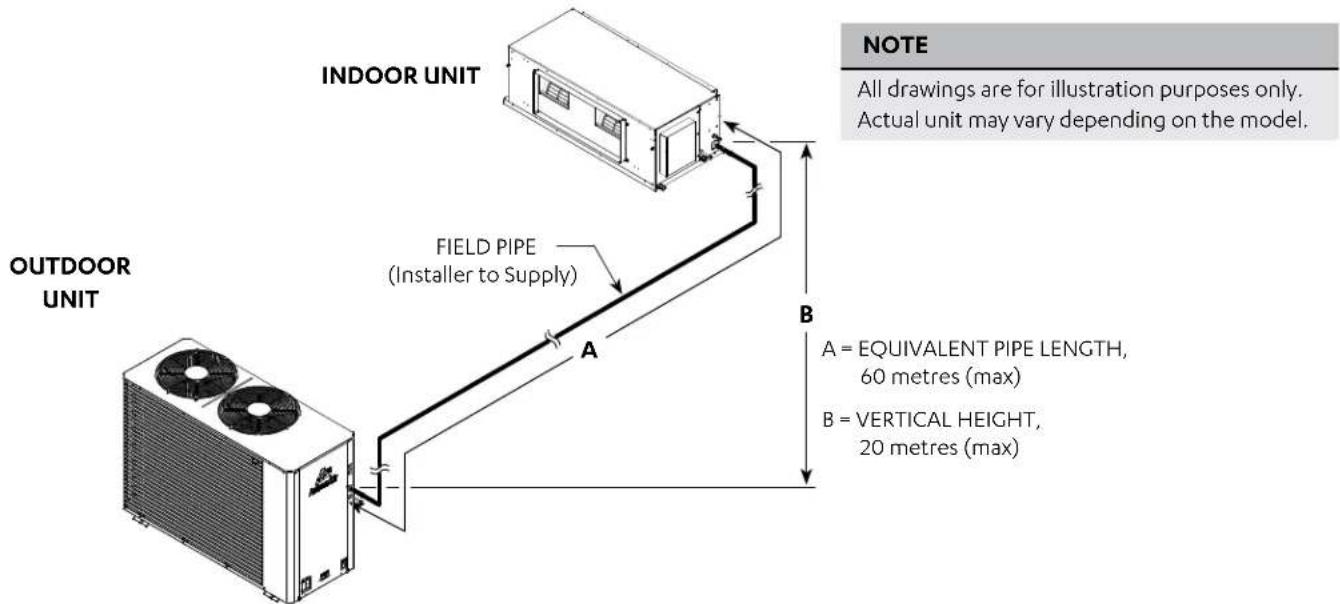
Example of Total Equivalent Field Pipe Length Calculations

Installation and Commissioning Guide
Advance Outdoor Units

CAUTION
Brazed joints should only be made while purging Nitrogen through the system.
Failure to do so will cause carbon deposit to be left on the internal pipe surface, that in turn can cause system failure and void warranty.

Installing interconnecting pipe work to indoor, nitrogen bleed procedure (First fit or rough in stage only)
- Run interconnecting pipe work from condenser location to evaporator.
- Release pressure in evaporator and remove caps.
- Fit copper tube into tail, set nitro bottle and regulator up at condenser end of pipe work.
- Fit nitrogen line into liquid line with rubber bung to seal the connection. The seal will prevent air being sucked into pipe work.
- Leave suction line open, set nitro regulator for nitrogen to flow through pipe work at 2 l/s flow rate @20kPa.
- Braze required joints as quick as possible. See Diagram Above.
Installing interconnecting pipe work to outdoor, nitrogen bleed procedure (First fit or rough in stage only)
- Starting with circuit 1 system, remove piping caps from the condenser and fit pipe work into tails.
- Fit nitro hose onto suction ball valve and fit open hose onto liquid line post valve.
- Set nitrogen regulator to 2 l/s flow rate through pipe work and evaporator.
- Braze remaining joints as quick as possible.
- Allow the brazed joints to cool and conduct leak test in the connections.
Installation and Commissioning Guide
Advance Outdoor Units
Pressure Testing
Pressurize the system to 2500kPa in stages. A recommended pressure test is to be performed for no less than 1 hour at 2500kPa.
NOTES
Importance of Evacuation:
- Any non-condensable product left in the system can cause the pressure in the high side of the system to increase and in turn, the compression temperature to rise.
- Moisture will result in adverse reaction in the refrigerant circuit.
• To prevent chemical reactions in the system, any moisture must be removed at all costs. - Oxygen (air) reacts with the compressor oil and can lead to faults such as compressor failure.

Evacuation Procedure (Triple Evacuation)
- Fit service gauges to the ball valves (liquid line service valve and suction line service valve).
- Evacuate the system to 1000 microns.
- Check vacuum with vacu stat. Break the vacuum with dry Nitrogen to 100kPa.
- Release Nitrogen pressure. Evacuate to 500 microns.
- Check vacuum with vacu stat. Break the vacuum with dry Nitrogen to 100kPa.
- Release Nitrogen pressure. Evacuate to 500 microns.
- Check vacuum with vacu stat. Let the unit stand for 1 hour and with the vacuum not rising above 500 microns.
- Open valve.
Installation and Commissioning Guide
Advance Outdoor Units
(As Shipped Position)
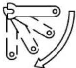
TO OPEN TURN ANTI-CLOCK WISE (1/4 TURN)


(Operating Position)

TO CLOSE TURN CLOCK WISE (1/4 TURN)
Installation and Commissioning Guide
Advance Outdoor Units
Specifications for Refrigeration
| TABLE : REFRIGERATION PIPING - SINGLE PHASE | ||||
| Reverse Cycle (Outdoor / Indoor) | CRV140S / EVV140S | CRV160S / EVV160S | CRV180S / EVV180S | |
| Max. Equivalent Pipe Length Range m | metres 0 - 60 0 | -60 0 - 60 | ||
| Max. Vertical Height Differential (1) | metres 20 | 20 20 | ||
| Field Pipe Size | ||||
| Liquid Line inch (mm) 3/8 (9.52) 3/8 (9.52) 3/8 (9.52) | ||||
| Gas Line inch (mm) 3/4 (19.05) 3/4 (19.05) | ||||
| Outdoor Pipe Size | ||||
| Liquid Line inch (mm) | 3/8 (9.52) swaged | 3/8 (9.52) swaged | 3/8 (9.52) swaged | |
| Gas Line inch (mm) | 3/4 (19.05) swaged | 3/4 (19.05) swaged | 3/4 (19.05) swaged | |
| Indoor Pipe Size | ||||
| Liquid Line inch (mm) | 3/8 (9.52) swaged | 3/8 (9.52) swaged | 3/8 (9.52) swaged | |
| Gas Line inch (mm) | 3/4 (19.05) swaged | 3/4 (19.05) swaged | 7/8 (22.22)(2)swaged | |
NOTES
(1) Included in maximum field pipe length.
(2) Cut swaged end on the unit to fit field pipe.
| TABLE : REFRIGERATION PIPING - THREE PHASE | |||||
| Reverse Cycle (Outdoor / Indoor) | CRV160T / EVV160S | CRV180T / EVV180S | CRV210T / EVV210S | CRV240T / EVV240S | |
| Max. Equivalent Pipe Length Range m | etres 0 - 60 0 | -60 0 - 60 0 - 60 | |||
| Max. Vertical Height Differential (1) | metres | 20 20 20 20 | |||
| Field Pipe Size | |||||
| Liquid Line | inch (mm) | 3/8 (9.52) 3/8 | (9.52) | 3/8 (9.52) or 1/2 (12.7) (2)(3) | 1/2 (12.7) |
| Gas Line | inch (mm) | 3/4 (19.05) 3/4 | (19.05) | 7/8 (22.2) or 1 (25.4) (2)(3) | 1 (25.4) |
| Outdoor Pipe Size | |||||
| Liquid Line | inch (mm) | 3/8 (9.52) swaged | 3/8 (9.52) swaged | 1/2 (12.7) (2) swaged | 1/2 (12.7) swaged |
| Gas Line | inch (mm) | 3/4 (19.05) swaged | 3/4 (19.05) swaged | 7/8 (22.2) swaged | 7/8 (22.2) swaged |
| Indoor Pipe Size | |||||
| Liquid Line | inch (mm) | 3/8 (9.52) swaged | 3/8 (9.52) swaged | 1/2 (12.7) (2) swaged | 1/2 (12.7) swaged |
| Gas Line | inch (mm) | 3/4 (19.05) swaged | 7/8 (22.2) (2) swaged | 1 (25.4) swaged | 1 (25.4) swaged |
NOTES
(1) Included in maximum field pipe length.
(2) Cut swaged end on the unit to for field pipe, if required.
(3) For pipe runs 20-60m 1/2" and 1" pipe must be used.
Installation and Commissioning Guide
Advance Outdoor Units
| Refrigerant Charge Details (R-410A) | |||||||||
| Model CRV140S | CRV1 | 60S | CRV180S | CRV160T | CRV180T | CRV210T | CRV240T | ||
| Refrigerant Type R-410A | R-410A | R-410A | R-410A | R-410A | R-410A | R-410A | |||
| Factory Charge | gms | 5580 | 6300 | 7580 | 6200 | 7850 | 7400 | 9350 | |
| Pre- charged Length | m | 15 | 15 | 15 | 15 | 15 | 15 | 15 | |
| Additional Refrigerant per charge | gms | 50 | 50 | 50 | 50 | 50 | 50 | 100 | 100 |
| Field Pipe Sizing In.(mm) | LIQ. | 3/8" (9.52) | 3/8" (9.52) | 3/8" (9.52) | 3/8" (9.52) | 3/8" (9.52) | 3/8" (9.52) ^(1) | 1/2"(12.7) | 1/2"(12.7) |
| GAS | 3/4"(19.05) | 3/4"(19.05) | 3/4"(19.05) | 3/4"(19.05) | 7/8"(22.22) | 7/8" (22.22) | 1" (25.4) | 1" (25.4) | |
NOTE
(1) 50grams per meter is only applicable if 3/8" liquid field pipe is used (for field pipe length between 0-20m).
Installation and Commissioning Guide
Advance Outdoor Units
Electrical Installation
All electrical work must be carried out by a qualified technician. Make sure all wiring is in accordance with local wiring rules. Wiring connections should be made in accordance with the wiring diagram provided.

DANGER
Live Electrical Supply!
- During installation of your air conditioning unit, it may be necessary to work in close proximity to live electricity. Only qualified technicians are allowed to perform these tasks.
- Follow all electrical safety precautions when exposed to live electrical components.
- Always make sure that all power supply, including remote controls, are disconnected before performing maintenance. Observe proper LOCK-OUT / TAG-OUT (LOTO) procedures to ensure that power cannot be inadvertently energised. Failure to disconnect power before maintenance procedure can result in serious injury or death.
- All electrical wiring must be in accordance with the relevant electrical authority rules and regulations.

CAUTION
STATIC SENSITIVE ELECTRONIC DEVICES!
- DO NOT handle electronic devices unless you are wearing an Anti-Static Wrist Strap that is connected to a EARTH. Failure to protect the electronic devices from static electricity may cause unrepairable damage.
- Static damaged electronic devices are NOT COVERED for replacement under warranty.
Wiring Diagram
The wiring diagrams specific for your air conditioning system are located on the inside of the electrical access panel.
Always refer all wiring installation, servicing and troubleshooting of this equipment to this diagram to ensure correct electrical connections are satisfied.
Supply and Power Requirements Procedure
It is the installer's responsibility to provide power supply wiring to the sub-mains isolator. Wiring should conform to the current electrical authority regulations and all wiring connections to be as per electrical diagram provided with the unit.
- Confirm that the power supply available is compatible with the unit nameplate ratings. The supply power must be within +10% to -6% of the rated voltage as per AS60038.
- Protect electrical service from over current and short circuit conditions in accordance with the latest edition of the AS/NZS 3000 "Australian / New Zealand Wiring Rules". Protection devices are to be sized accordingly as per to the electrical specifications of the unit.
- Complete the outdoor unit power supply wiring into the sub-mains isolator.
- Secure the power cords and control cables that enters in/exits out the unit. Use the cable ties provided in the electrical panels.
- Provide proper unit earthing in accordance with local and national wiring rules.
- Installer to connect an appropriate load break (AC3) isolator in sub mains wiring.
Compressor Voltage Balance Requirement
Check the voltage at the mains supply terminals to determine if it is balanced. Voltage imbalance on three phase systems can cause motor overheating and premature failure. The maximum allowable imbalance is +2.0% should voltage imbalance exceed this value, check unit wiring connections to locate and rectify faults or contact local supply authority.
Crankcase Heater
Crankcase Heater is to be disconnected for pipe lengths 8m or less.
Installation and Commissioning Guide
Advance Outdoor Units
Electrical Connection
NOTES
• To minimise noise interference, Data and Power cable clearance should be maintained as much as possible.
- All drawings are for illustration purposes only. Actual unit may vary depending on the model.
DETAILED WIRING DIAGRAM IS PROVIDED WITH THE UNIT.
Outdoor Unit: Located at the back of electrical/compressor access panel. Indoor Unit: Located at the back of electrical box cover.
Split Unit
① MAINS WIRING (230/400VAC)
(Single Phase + Neutral + Earth) 50Hz
(Three Phase + Neutral + Earth) 50Hz
—② INTER-CONNECTING POWER CABLE (230VAC)
(Single Phase + Neutral + Earth) 50Hz
③ DATA CABLE TO WALL CONTROLLER
(Cat5e UTP (AWG 24) Data Cable)
----④ EXTRA LOW VOLTAGE DATA CONTROL WIRING
(2 Core Shielded Twisted Pair 7/0.30 (0.5mm²) Data Cable)

flowchart
graph TD
    A["OUTDOOR UNIT"] --> B["SUB-MAINS CIRCUIT BREAKER"]
    B --> C["① MAIN SUPPLY FROM DISTRIBUTION BOARD"]
    C --> D["SUB-MAINS ISOLATOR (Field Supplied by Installer)"]
    D --> E["SUB-MAIN TO UNIT"]
    E --> F["INDOOR UNIT"]
    F --> G["② INTER-CONNECTING POWER CABLE OUTDOOR - INDOOR"]
    F --> H["③ DATA CABLE (Supplied with the unit) 20m"]
    F --> I["INTER-CONNECTING DATA CONTROL CABLE INDOOR TO OUTDOOR"]
    F --> J["WALL CONTROLLER"]
    J --> K["④ INTER-CONNECTING DATA CONTROL CABLE INDOOR TO OUTDOOR"]
Installation and Commissioning Guide
Advance Outdoor Units
Data Cable Shielding Instructions
2 Core Twisted (ActronAir Part Number: AEDC2)
NOTES
- Maintain the twist of the core wires up to the Green Terminal Plug.
• Maximum strip length of outer insulation to the Green Terminal Plug is 50mm. - Make sure the cable colors used for the Data Terminal in Outdoor Unit match the Data Terminal in Indoor unit.
Outdoor Unit Data Terminal (Green Plug)
"Terminal A" - White Wire
"Terminal B" - Black Wire
"Terminal G" - Shield Wire
Indoor Unit Data Terminal (Green Plug)
"Terminal A (+)" - White Wire
"Terminal B (-)" - Black Wire
"Terminal G" - Shield Wire
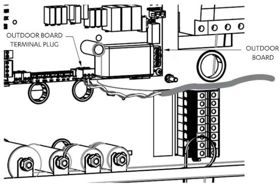
Insert data cable through the lower snap bushing and first cable tie on the right hand side of the electrical panel.
Connect core wires and shield wire into the Outdoor Board green terminal plug marked "INDOOR A, B and G". (Refer to unit wiring diagram for complete wiring connection details).
NOTE
All drawings are for illustration purposes only. Actual unit may vary depending on the model.
Installation and Commissioning Guide
Advance Outdoor Units
Circuit Breaker Size and Cable Size Requirement
| Model | Circuit Breaker Size | Cable Size * (mm2) | |
| Amps MAIN O. | .D. to I.D. | ||
| CRV140S/EVV140S 25.0 4.0 1.0 | |||
| CRV160S/EVV160S 32.0 6.0 1.0 | |||
| CRV180S/EVV180S 32.0 6.0 1.0 | |||
| CRV160T/EVV160S 20.0 2.5 1.0 | |||
| CRV180T/EVV180S 20.0 2.5 1.0 | |||
| CRV210T/EVV210S 25.0 4.0 1.5 | |||
| CRV240T/EVV240S 25.0 4.0 1.5 | |||
* Suggested Minimum Cable Size should be used as a guide only, refer to AS/NZS 3000 “Australian / New Zealand Wiring Rules” for more details.
Installation and Commissioning Guide
Advance Outdoor Units
Wall Controller Options
Wall Controller Options
Maximum of three (3) wall controllers in below combinations is allowed on unit. See below table.
| Options | Wall Controllers | ||
| C1 C2 C3 | |||
| 1st Option NEO | |||
| 2nd Option NEO | NEO | ||
| 3rd Option NEO | NEO LR7-1 / LC7-2 | ||
| 4th Option NEO LR7-1 / LC7-2 | |||
| 5th Option NEO LR7-1 / LC7-2 LR7-1 | / LC7-2 | ||
| 6th Option LR7-1 / LC7-2 | |||
| 7th Option LR7-1 / LC7-2 LR7-1 / LC7-2 | |||
| 8th Option LR7-1 / LC7-2 LR7-1 / LC7-2 LR7-1 / LC7-2 | |||
NOTES
• NEO - Available in White (NTW-1000) and Black (NTB-1000) colors.
• LC7-2, LR7-1 and LM-RS-2 - Available in White and Grey colors.
- In the instance of a combination of NEO and LR7-1 / LC7-2 being connected together, the NEO will always need to be addressed as C1.
Installation and Commissioning Guide
Advance Outdoor Units
Wiring Configuration : Recommended
NOTES

flowchart
graph TD
    A["INDOOR UNIT"] -->|① DATA CONTROL CABLE| B["OUTDOOR UNIT"]
    B -->|②a| C["NEO WALL CONTROLLER 1 (OPTIONAL)"]
    B -->|②b| D["NEO WALL CONTROLLER 2 (OPTIONAL)"]
    B -->|②c| E["LR7-1 WALL CONTROLLER 3 (OPTIONAL)"]
    C --> F["LM-RS-2 (OPTIONAL)"]
    D --> F
    E --> F
    F --> G["AERSS (OPTIONAL)"]
    style A fill:#f9f,stroke:#333
    style B fill:#ccf,stroke:#333
    style C fill:#cff,stroke:#333
    style D fill:#cff,stroke:#333
    style E fill:#ffc,stroke:#333
    style F fill:#cfc,stroke:#333
    style G fill:#fcc,stroke:#333
| Item Description Maximum Cable Length | |
| 1 to 4 Outdoor PCB to Indoor PCB 100 m | |
| 4 to 2a, 4 to 2b Indoor PCB to Wall Controller 90 m | |
| 4 to 2c Indoor PCB to Wall Controller 3100 m | |
| 4 to 3 Indoor PCB to Remote Sensor 100 m |
| Description Cable Type | |
| Indoor to Wall Controller Cat5e UTP (AWG 24) Data Cable | |
| Indoor to Remote Sensor | Cat5e UTP (AWG 24) Data Cable |
| Indoor to Outdoor Data Cable | 2 Core (1 Pair) Twisted Pair, 7/0.30 (0.5mm ^2 ) Shielded Data Cable |
Installation and Commissioning Guide
Advance Outdoor Units
- Diagram shown below is a general representation only. Refer to individual unit wiring diagram for complete wiring connection details.
- Long runs beside Mains cables or TV antenna cables should be avoided where possible.
- Wiring configuration for LR7-1 and LC7-2 wall controller is the same.
- Daisy connection not allowed for NEO wall controller.
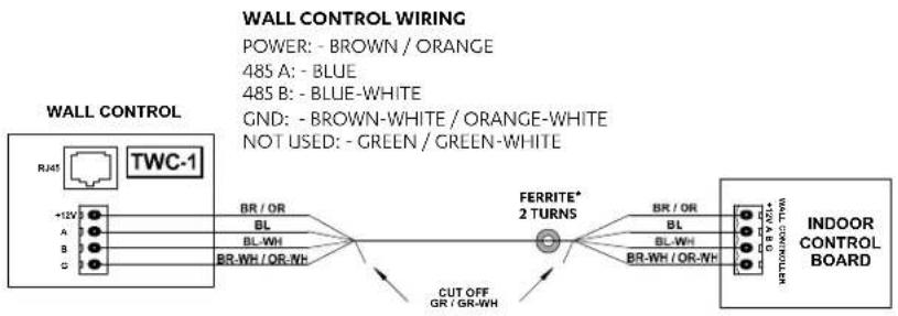
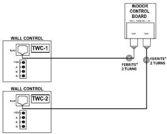
- For the Neo controllers the cable MUST be looped twice through the ferrite ring.
- Ferrite must be installed 50mm to 100mm from the CMI board.

flowchart
graph TD
    A["INDOOR UNIT"] --> B["Outdoor Unit"]
    B --> C["LM-RS-2 (OPTIONAL)"]
    B --> D["AERSS (OPTIONAL)"]
    C --> E["LR7-1 WALL CONTROLLER 1 (OPTIONAL)"]
    C --> F["LR7-1 WALL CONTROLLER 2 (OPTIONAL)"]
    C --> G["LR7-1 WALL CONTROLLER 3 (OPTIONAL)"]
    B --> H["DATA CONTROL CABLE"]
    style A fill:#f9f,stroke:#333
    style B fill:#ccf,stroke:#333
    style C fill:#cfc,stroke:#333
    style D fill:#fcc,stroke:#333
    style E fill:#ffc,stroke:#333
    style F fill:#ffc,stroke:#333
    style G fill:#ffc,stroke:#333
| Item | Description | Maximum Cable Length |
| 1 to 4 Outdoor | PCB to Indoor PCB 100m | |
| 4 to 2a Indoor | PCB to Wall Controller 1 100m | |
| 4 to 2c Indoor | PCB to Wall Controller 3 (last controller) 75m total (Daisy Chain)** | |
| 4 to 3 Indoor | PCB to Remote Sensor 100m |
** Maximum Daisy Chain connection is up to 2 wall Controllers.
| Description | Cable Type |
| Indoor to Wall Controller Cat5e UTP (AWG 24) Data Cable | |
| Indoor to Remote Sensor | Cat5e UTP (AWG 24) Data Cable |
| Indoor to Outdoor Data Cable | 2 Core (1 Pair) Twisted Pair, 7/0.30 (0.5mm2) Shielded Data Cable |
Installation and Commissioning Guide
Advance Outdoor Units
Wiring Connections
LR7-1 and LC7-2 Wall Control Wiring Connections

NEO Wall Control Wiring Connections
NOTES
The controller wiring MUST be looped twice through the ferrite ring.
* Ferrite must be installed 50mm to 100mm from the indoor electrical box.
NEO Hard Wiring
flowchart
graph LR
    A["+12V"] --> B["RJ45 TWC-1"]
    C["A"] --> B
    D["B"] --> B
    E["C"] --> B
    B --> F["BR / OR BL BL-WH BR-WH / OR-NH"]
    F --> G["FERRITE* 2 TURNS"]
    G --> H["BR / OR BL BL-WH BR-WH / OR-NH"]
    H --> I["INDOOR CONTROL BOARD"]
    style G fill:#f9f,stroke:#333
    style H fill:#ccf,stroke:#333
NEO RJ45 Wiring
flowchart
graph TD
    A["INDOOR CONTROL BOARD"] -->|FERRITE* 2 TURNS| B["Indoor Control Board"]
    C["WALL CONTROL"] -->|+12V A G| D["TWC-1"]
    E["WALL CONTROL"] -->|+12V A B G| F["TWC-2"]
    D --> G["FERRITE* 2 TURNS"]
    F --> H["FERRITE* 2 TURNS"]
Installation and Commissioning Guide
Advance Outdoor Units
LM-RS-2 Optional Sensor Wiring Connections
REMOTE SENSOR WIRING
PAIR 1: - BLUE / BLUE-WHITE
PAIR 2: - ORANGE / ORANGE-WHITE
PAIR 3: - GREEN / GREEN-WHITE
PAIR 4: - BROWN / BROWN-WHITE
NOTE:
• PAIR 1 AND 2 USED FOR ILLUSTRATION PURPOSES ONLY.
- CUT OFF AND TERMINATE ANY UNUSED PAIRS TO ENSURE NO WIRING IS LEFT EXPOSED.

flowchart
graph TD
    A["INDOOR CONTROL BOARD"] --> B["TEMP SENSORS"]
    B --> C["S1 S2 S3 COM"]
    B --> D["PWR 1"]
    B --> E["PWR 2"]
    B --> F["PWR 3"]
    B --> G["PWR 4"]
    B --> H["PWR 5"]
    B --> I["PWR 6"]
    B --> J["PWR 7"]
    B --> K["PWR 8"]
    B --> L["PWR 9"]
    B --> M["PWR 10"]
    B --> N["PWR 11"]
    B --> O["PWR 12"]
    B --> P["PWR 13"]
    B --> Q["PWR 14"]
    B --> R["PWR 15"]
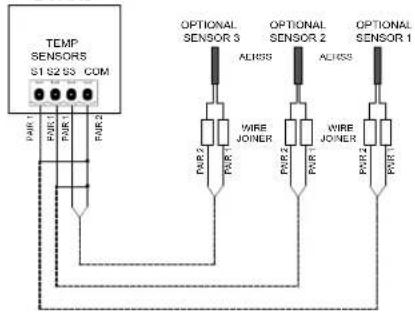
AERSS Optional Duct Sensor Wiring Connections
REMOTE SENSOR WIRING
PAIR 1: - BLUE / BLUE-WHITE
PAIR 2: - ORANGE / ORANGE-WHITE
PAIR 3: - GREEN / GREEN-WHITE
PAIR 4: - BROWN / BROWN-WHITE
NOTE:
• PAIR 1 AND 2 USED FOR ILLUSTRATION PURPOSES ONLY.
- CUT OFF AND TERMINATE ANY UNUSED PAIRS TO ENSURE NO WIRING IS LEFT EXPOSED.
INDOOR
CONTROL
BOARD
flowchart
graph TD
    A["TEMP SENSORS S1 S2 S3 COM"] -->|FAIR 1| B["OPTIONAL SENSOR 3"]
    A -->|FAIR 2| C["OPTIONAL SENSOR 2"]
    A -->|FAIR 3| D["OPTIONAL SENSOR 1"]
    B --> E["WIRE JONER"]
    C --> F["WIRE JONER"]
    D --> G["WIRE JONER"]
    E --> H["ACROSS"]
    F --> I["ACROSS"]
    G --> J["ACROSS"]
Installation and Commissioning Guide
Advance Outdoor Units
Demand Response Management
These products are compliant to AS/NZS 4755.3.1:2012

- Route DRM input cables into the Unit (as per previous wiring installation procedure).
- Connect cables into terminals (as per wiring diagram provided with the unit).
| Demand Management Mode | Description Of Mode Allowable Range (%) | Operating Mode |
| DRM1 Compressor Off Mode | Compressor ONLY will cycle Off and remain Off for the entire Demand Response event. All other functions will operate as normal (i.e. Indoor Fan) | |
| DRM2 | Maximum 50% power use mode with 0 to <50% allowable power use range | Compressor 0 to <50% operation range for the total Demand Response event. |
| DRM3 | Maximum 75% power use mode with 0 to <75% allowable power use range | Compressor 0 to <75% operation range for the total Demand Response event. |
DEMAND RESPONSE ENABLING DEVICE CIRCUIT DIAGRAM

flowchart
graph LR
    A["DRED VOLTAGE FREE CONTACTS"] --> B["DEMAND RESPONSE ENABLING DEVICE (DRED) AS4755 COMPLIANT DEVICE (OPTIONAL)"]
    C["ODU CPU BOARD"] --> D["+12V/COM"]
    C --> E["DRM 3/COMP"]
    C --> F["DRM 2/FAN"]
    C --> G["DRM 1/HEAT"]
    C --> H["DEMAND RESPONSE MANAGEMENT"]
NOTE
- Demand Response Management is not applicable when using third party control.
- All drawings are for illustration purposes only. Actual unit may vary depending on the model.
Installation and Commissioning Guide
Advance Outdoor Units
Configuring and Commissioning Setup
Menu and Navigation
| diS(Display) | Display system's status and settings | |
| SEr(Service) | Service use only | |
| SEt(Settings) | cnFg | 04.00 = Family* |
| 04.24 = Capacity* | ||
| CtrS | Ct. 0 = Third Party | |
| Ct. 1 = Wall Control (default) | ||
| Ct. 2 = Basic BMS | ||
| Ct. 3 = Wall Control + Basic BMS | ||
| Ct. 4 = Advanced BMS | ||
| iduS | FP1 = IDU Fan Low PWM setting | |
| FP2 = IDU Fan Med PWM setting | ||
| FP3 = IDU Fan High PWM setting | ||
| Fr1 = IDU Fan Low RPM setting | ||
| Fr2 = IDU Fan Med RPM setting | ||
| Fr3 = IDU Fan High RPM setting | ||
| FPd = IDU Fan Defrost PWM setting | ||
| FPc = IDU Reduced Airflow PWM setting | ||
| FiL = IDU Fan Filter Hours setting | ||
| Econ = IDU Econ 0-10V Output setting | ||
| FnSE = Indoor Fan Setting | ||
| HtSt = HotStart On/Off | ||
| SoFt | no = Soft Start not enabled (default) | |
| YES = Soft Start enabled | ||
| run | no = Indoor Fan and Compressor (default) | |
| YES = Compressor only | ||
| odFs | Hi= High Start-up Speed (default) | |
| Lo= Low Start-up Speed | ||
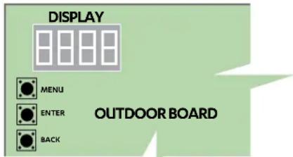
MENU
Scroll through the items at the same menu level.
Increment the value being set.
ENTER
Go into the selected menu.
Lock in selected value.
BACK
Go back to the parent menu.
Press and hold to go back to main menu.
* Family and Capacity are the representative values only and may vary depend on the model purchased as seen below table. Do not change setting.
| Family and Capacity Table | |||||||
| Model | CRV140S | CRV160S | CRV180S | CRV160T | CRV180T | CRV210T | CRV240T |
| Family Capacity (kW) | |||||||
| 04 - - - | 6 18 | 21 24 | |||||
| 05 14 16 | 18 - - - | ||||||
Configuring Compressor and Capacity(cnFg)
Configure the compressor type and capacity. The unit is factory configured. Do not change this setting.
Configuring Control Source (CtrS)
This commissioning is applicable for BMS and third party control.
Configurable settings are as follows:
Third Party Control
The unit can be controlled by non-ActronAir wall control. To do this, CtrS on the Outdoor Board has to be set to Ct. 0.
For connection details, see the wiring diagram supplied with the outdoor unit.
Installation and Commissioning Guide
Advance Outdoor Units
Wall Control
ActronAir offers NEO, LR7-1 and LC7-2, wall controls that can control the available features and maximise the function and operation of the air conditioner. To do this, CtrS on the Outdoor Board must be set to Ct. 1.
Basic BMS
The unit can be connected to a network through a BMS card (ICUNO-MOD). This allows the unit to be operated in the same way the as the NEO, LR7-1 and LC7-2 does. To do this, CtrS on the Outdoor Board must be set to Ct. 2.
Wall Control + Basic BMS
The unit can be connected to a network (Basic BMS) and at the same time be controlled using the NEO, LR7-1 or LC7-2 controller. Priority will be given to the most recent command. To do this, CtrS on the Outdoor Board must be set to Ct. 3.
Advanced BMS
The unit can be connected for system that requires customised functions not included in the existing software or logic in the Outdoor Board but still retaining the safety logic. To do this, CtrS on the Outdoor Board must be set to Ct. 4.
Auto Fan Function
Auto fan function can only be commissioned by ActronAir wall control such as NEO, LR7-1 and LC7-2.
Installation and Commissioning Guide
Advance Outdoor Units
Third Party Control Input (Indoor and/or Outdoor Board)
This option allows Fan, Compressor and Reversing Valve to be controlled by a Third Party Control. There are two ways on how the Indoor Fan may be controlled, using 0-10V Analogue Input or Fixed Indoor Fan Speed.
NOTE
- Demand Response Management (DRM) is not available if Third Party Control Option is used.
- Make ensure control source has been configured for Third Party Control.
0-10V Analogue Input for Compressor and Indoor Fan
Indoor Fan Connection (Indoor Board)

| Input (DC) Output Fan Status | |
| 0.0V to 0.99 V 0% Off | |
| 1.0V to 1.49 V 0 or 20% Off or On | |
| 1.5V to 9.5 V 20% to 100% On | |
| 9.5V to 10 V 100% On |
Compressor and Reversing Valve Connection (Outdoor Board)

| Input (DC) Output | Compressor Status | |
| 0 - 0.99 V | 0% | Off |
| 1 - 1.49 V | 0 or 20% | Off/On (hysteresis) |
| 1.5 - 9.5 V | 20% to 100% | On |
| 9.5 - 10 V | 100% | On |
NOTES
- As the compressor turns ON and the Indoor fan signal is not available then indoor fan will start to run on medium PWM speed.
- Indoor fan low and high PWM limits depends upon the model.
- The Voltage can be linearly interpolated using the above table to determine the desired PWM or unit output.
Installation and Commissioning Guide
Advance Outdoor Units
0-10V Analogue Input for Compressor with Fixed Indoor Fan Speed
This feature allows for the Indoor Fan to be controlled externally (ON/OFF only).
Fan, Compressor and Reversing Valve Connection (Outdoor Board)

NOTES
- As the compressor turns ON and the Indoor fan signal is not available then indoor fan will start to run on medium PWM speed.
- Indoor fan operation when fan signal is available:
- Compressor ON: Indoor fan will run on medium speed.
- Compressor OFF: Indoor fan will run on reduce airflow operation.
Input for Fixed Compressor with Fixed Indoor Fan Speed
This feature allows for both Compressor and Indoor Fan to be controlled externally (ON/OFF only).
Fan, Compressor and Reversing Valve Connection (Outdoor Board)

flowchart
graph LR
    A["THIRD PARTY COMPRESSOR CONTROL INPUT"] --> B["COMPRESSOR"]
    A --> C["INDOOR FAN"]
    A --> D["HEAT"]
    B --> E["+12VDC"]
    C --> E
    D --> E
    E --> F["+12V COM"]
    E --> G["DRM3 COMP"]
    E --> H["DRM2 FAN"]
    E --> I["DRM1 HEAT"]
NOTES
- As the compressor turns ON and the Indoor fan signal is not available then indoor fan will start to run on medium PWM speed.
- Indoor fan operation when fan signal is available:
- Compressor ON: Indoor fan will run on medium speed.
- Compressor OFF: Indoor fan will run on reduce airflow operation.
- Compressor turns on with 100% speed request.
- Although the compressor will have 100% speed request, the speed may vary depending on compressor safety requirements.
Installation and Commissioning Guide
Advance Outdoor Units
0-10V Analogue Input for Indoor Fan with Fixed Speed Compressor
This feature allows for the compressor to be controlled externally (ON/OFF only).
Indoor Fan Connection (Indoor Board)

| Input (DC) Output Fan Status | |
| 0.0 V to 0.99 V 0% Off | |
| 1.0 V to 1.49 V 0 or 20% Off or On | |
| 1.5 V to 9.5 V 20% to 100% On | |
| 9.5 V to 10 V 100% On |
Fan, Compressor and Reversing Valve Connection (Outdoor Board)

NOTES
- As the compressor turns ON and the Indoor fan signal is not available then indoor fan will start to run on medium PWM speed.
- If the compressor turn ON, during reduced fan operation, the controller will increase the fan speed to the "low PWM fan limit" if it is running less than the low PWM Limits.
- Indoor fan low and high PWM limits depends upon the model.
- The Voltage can be linearly interpolated using the above table to determine the desired PWM or unit output.
- Compressor turns on with 100% speed request.
Run and Fault Indication Output (Outdoor Board)
To activate, the unit must be wired as illustrated below. If required, a fault output connection terminal is also available to show any error/fault with the a/c system. RUN/FAULT relay outputs (230VAC/5A MAX) connection.
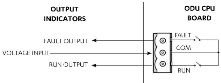
flowchart
graph LR
    A["OUTPUT INDICATORS"] --> B["FAULT OUTPUT"]
    A --> C["VOLTAGE INPUT"]
    A --> D["RUN OUTPUT"]
    E["ODU CPU BOARD"] --> F["FAULT"]
    E --> G["COM"]
    E --> H["RUN"]
Installation and Commissioning Guide
Advance Outdoor Units
Run Output is configurable to indicate that the unit is running. There are two configurations in which this can be set:
- Either the compressor or the Indoor Fan only is running
- Only Compressor is running.
By default, this is set to turn on when either indoor fan or compressor is operating. To set up to compressor run indication only, in OD Board Menu follow below steps.
- Using the MENU and the ENTER Buttons on the outdoor PCB, navigate to SET (Settings) →run (Unit Operation Indicator Settings).
- If required, press MENU to navigate to YES.
Remote On/Off

| Turning the system On and Off by remote method | |
| Turning the system On | St atus 1: The system is Off and the remote switch/relay has been left in the open position.1. Close remote switch/relay.2. System will start in approximately 1 minute. |
| St atus 2: The system is Off and the remote switch/relay has been left in the closed position.1. Open remote switch/relay for a minimum of 5 seconds.2. Close remote switch/relay.3. System will start in approximately 30 seconds. | |
| Turning the system Off | St atus 3: The system is On and the remote switch/relay has been left in the closed position.1. Open remote switch/relay.2. System will turn Off in approximately 1 minute. |
| St atus 4: The system is On and the remote switch/relay has been left in the open position.1. Close remote switch/relay for a minimum of 5 seconds.2. Open remote switch/relay.3. System will turn Off in approximately 30 seconds. | |
Installation and Commissioning Guide
Advance Outdoor Units
Indoor Fan Commissioning
EVV140S / EFV140S
| APPLICATION RANGE (COMPRESSOR ON) * | |||||||||||
| AIRFLOW(l/s) | EXTERNAL STATIC PRESSURE (Pa) | ||||||||||
| 50 100 150 | 200 250 | ||||||||||
| % PWM | W | % PWM | W | % PWM | W | % PWM | W | % PWM | W | % PWM | |
| 500 | 28 | 100 | 35 | 151 | 40 | 206 | 46 | 268 | 51 | 330 | |
| 550 | 32 | 121 | 39 | 179 | 44 | 227 | 50 | 295 | 55 | 360 | |
| 600 | 37 | 145 | 44 | 207 | 49 | 263 | 54 | 326 | 60 | 394 | |
| 630 | 40 | 162 | 47 | 220 | 52 | 285 | 58 | 351 | 63 | 417 | |
| 650 | 42 | 173 | 48 | 229 | 54 | 299 | 60 | 368 | 65 | 432 | |
| 700 | 47 | 197 | 53 | 260 | 60 | 334 | 65 | 400 | 72 | 480 | |
| 750 | 52 | 227 | 60 | 303 | 66 | 379 | 72 | 449 | 96 | 709 | |
NOTES
* Only applicable to Third Party controllers
W = Indoor Fan Power, Watts
PWM = Pulse Width Modulation Setting, % PWM (Adjustable through the LR7-1, LC7-2, NEO or Outdoor Board).
| Default Fan Speed Value at 100 Pa | |
| Speed | Default PWM (adjustable) |
| High PWM (%) | 60 |
| Medium PWM (%) | 47 |
| Low PWM (%) | 35 |
| Indoor Fan PWM Limits | |
| High PWM Limit | 99 |
| Low PWM Limit | 28 |
Installation and Commissioning Guide
Advance Outdoor Units
EVV140S / EFV140S : Three Speed Application Fan Curve

line
| Airflow (l/s) | External Static Pressure (Pa) | Label | | ------------- | ------------------------------ | --------- | | 300 | 220 | 1.26 A | | 370 | 200 | 1.44 A | | 430 | 150 | 1.31 A | | 510 | 100 | 1.77 A | | 580 | 50 | 1.02 A | | 640 | 100 | 1.62 A | | 700 | 50 | 1.45 A | | 750 | 100 | 2.09 A | | 800 | 50 | 1.89 A | | 450 | 250 | 2.11 A | | 580 | 250 | 2.68 A | | 700 | 200 | 2.49 A | | 750 | 150 | 2.28 A | | 800 | 100 | 60% PWM |Installation and Commissioning Guide
Advance Outdoor Units
EVV140S / EFV140S : Third Party Application Fan Curve

contour
| AIRFLOW (l/s) | EXTERNAL STATIC PRESSURE (Pa) | Power Level (PWM) | | ------------- | ----------------------------- | ----------------- | | 500 | 250 | 25% PWM | | 550 | 200 | 30% PWM | | 600 | 150 | 35% PWM | | 650 | 100 | 40% PWM | | 700 | 50 | 45% PWM | | 750 | 25 | 50% PWM | | 630 | 100 | 47% PWM | | 650 | 150 | 60% PWM | | 700 | 200 | 65% PWM | | 750 | 250 | 70% PWM | | 750 | 250 | 75% PWM | | 750 | 250 | 85% PWM | | 750 | 250 | 95% PWM |Installation and Commissioning Guide
Advance Outdoor Units
EVV160S / EFV160S
| APPLICATION RANGE (COMPRESSOR ON) * | ||||||||||
| AIRFLOW(l/s) | EXTERNAL STATIC PRESSURE (Pa) | |||||||||
| 50 100 150 | 200 250 | |||||||||
| % PWM | W | % PWM | W | % PWM | W | % PWM | W | % PWM | W | |
| 600 | 36 | 147 | 42 | 203 | 47 | 257 | 52 | 315 | 57 | 378 |
| 650 | 41 | 173 | 46 | 225 | 52 | 291 | 58 | 362 | 63 | 423 |
| 700 | 45 192 | 52 266 | 58 334 | 63 | 400 | 70 471 | ||||
| 750 | 51 | 228 | 58 | 304 | 63 | 372 | 69 | 446 | ||
| 800 | 57 262 | 63 | 340 | 69 419 | 80 | 505 | ||||
| 850 | 63 | 305 | 69 | 386 | 78 | 482 | MOTOR / BLOWER UNIT | |||
| 900 | 69 | 348 | 77 | 442 | 91 | 538 | ||||
NOTES
* Only applicable to Third Party controllers
W = Indoor Fan Power, Watts
PWM = Pulse Width Modulation Setting, % PWM (Adjustable through the LR7-1, LC7-2, NEO or Outdoor Board).
| Default Fan Speed Value at 100 Pa | |
| Speed | Default PWM (adjustable) |
| High PWM (%) | 77 |
| Medium PWM (%) | 58 |
| Low PWM (%) | 42 |
| Indoor Fan PWM Limits | |
| High PWM Limit | 99 |
| Low PWM Limit | 36 |
Installation and Commissioning Guide
Advance Outdoor Units
EVV160S / EFV160S : Three Speed Application Fan Curve

line
| AIRFLOW (l/s) | External STATIC PRESSURE (Pa) | Label | | ------------- | ------------------------------ | --------- | | 350 | 215 | 1.50 A | | 450 | 200 | 1.75 A | | 550 | 150 | 1.60 A | | 600 | 100 | 1.46 A | | 650 | 50 | 1.29 A | | 700 | 150 | 2.30 A | | 750 | 100 | 2.11 A | | 800 | 250 | 3.35 A | | 850 | 150 | 3.32 A | | 900 | 100 | 3.18 A | | 950 | 50 | 2.98 A | | 1000 | 0 | 2.74 A |Installation and Commissioning Guide
Advance Outdoor Units
EVV160S / EFV160S : Third Party Application Fan Curve

contour
| AIRFLOW (l/s) | External Static Pressure (Pa) | Power Level | | ------------- | ------------------------------ | ----------- | | 600 | 0 | 30% PWM | | 650 | 50 | 35% PWM | | 700 | 100 | 40% PWM | | 750 | 150 | 45% PWM | | 800 | 200 | 50% PWM | | 850 | 250 | 55% PWM | | 900 | 250 | 60% PWM | | 950 | 250 | 65% PWM | | 1000 | 250 | 70% PWM | | 1050 | 250 | 75% PWM | | 1100 | 250 | 80% PWM | | 1150 | 250 | 85% PWM | | 1200 | 250 | 90% PWM | | 1250 | 250 | 95% PWM | | 1300 | 250 | 99% PWM |Installation and Commissioning Guide
Advance Outdoor Units
EVV180S / EFV180S
| APPLICATION RANGE (COMPRESSOR ON) * | ||||||||||||
| AIRFLOW(l/s) | EXTERNAL STATIC PRESSURE (Pa) | |||||||||||
| 50 100 150 | 200 250 | % PWM | W | % PWM | W | % PWM | W | |||||
| % PWM | W | % PWM | W | |||||||||
| 680 43 | 184 50 | 250 | 56 | 317 | 61 | 385 | 67 | 452 | ||||
| 700 | 45 | 192 | 52 | 266 | 58 | 334 | 63 | 400 | ||||
| 750 | 51 | 228 | 58 | 304 | 63 | 372 | 69 | 446 | ||||
| 800 | 57 | 262 | 63 | 340 | 69 | 419 | 80 | 505 | ||||
| 850 | 63 | 305 | 69 | 386 | 78 | 484 | ||||||
| 900 | 69 | 348 | 77 | 440 | 91 | 540 | ||||||
| 950 | 77 | 404 | 85 | 498 | ||||||||
| 1000 | 85 | 461 | ||||||||||
| 1020 | 89 | 486 | ||||||||||
NOTES
* Only applicable to Third Party controllers
W = Indoor Fan Power, Watts
PWM = Pulse Width Modulation Setting, % PWM (Adjustable through the LR7-1, LC7-2, NEO or Outdoor Board).
| Default Fan Speed Value at 100 Pa | |
| Speed | Default PWM (adjustable) |
| High PWM (%) | 99 |
| Medium PWM (%) | 69 |
| Low PWM (%) | 50 |
| Indoor Fan PWM Limits | |
| High PWM Limit | 99 |
| Low PWM Limit | 43 |
Installation and Commissioning Guide
Advance Outdoor Units
EVV180S / EFV180S : Three Speed Application Fan Curve

line
| AIRFLOW (l/s) | External Static Pressure (Pa) | Label | | ------------- | ------------------------------ | --------- | | 370 | 250 | 1.98 A | | 700 | 200 | 2.01 A | | 750 | 150 | 1.89 A | | 750 | 100 | 1.77 A | | 850 | 100 | 1.52 A | | 850 | 250 | 2.85 A | | 850 | 200 | 2.94 A | | 850 | 150 | 2.75 A | | 850 | 100 | 2.54 A | | 900 | 50 | 2.37 A | | 950 | 100 | 3.62 A | | 1050 | 50 | 3.48 A | | Nominal Airflow = 850 l/s | - | - | | HI-Mid-Low Speed Airflow Range | - | 99% PWM | | HI-Mid-Low Speed Airflow Range | - | 3.70 A | | HI-Mid-Low Speed Airflow Range | - | 3.64 A | | HI-Mid-Low Speed Airflow Range | - | 3.74 A | | HI-Mid-Low Speed Airflow Range | - | 3.70 A | | HI-Mid-Low Speed Airflow Range | - | 3.48 A |Installation and Commissioning Guide
Advance Outdoor Units
EVV180S / EFV180S : Third Party Application Fan Curve

contour
| AIRFLOW (l/s) | EXTERNAL STATIC PRESSURE (Pa) | Power Level (PWM) | | ------------- | ----------------------------- | ----------------- | | 650 | 250 | 99% PWM | | 700 | 200 | 90% PWM | | 750 | 150 | 80% PWM | | 800 | 100 | 70% PWM | | 850 | 100 | 69% PWM | | 900 | 150 | 65% PWM | | 950 | 200 | 60% PWM | | 1000 | 250 | 55% PWM | | 1050 | 250 | 50% PWM | | 1050 | 250 | 45% PWM | | 1050 | 250 | 40% PWM | | 1050 | 250 | 35% PWM |Installation and Commissioning Guide
Advance Outdoor Units
EVV210S / EFV210S
| APPLICATION RANGE (COMPRESSOR ON) * | ||||||||||||
| AIRFLOW(l/s) | EXTERNAL STATIC PRESSURE (Pa) | |||||||||||
| 50 100 150 | 200 250 300 | % PWM | W | % PWM | W | % PWM | W | % PWM | W | |||
| % PWM | W | % PWM | W | |||||||||
| 810 | 38 | 192 | 43 | 266 | 49 | 333 | 54 | 408 | 59 | 484 | 70 | 561 |
| 850 | 41 | 214 | 46 | 279 | 51 | 349 | 57 | 437 | 62 | 511 | 74 | 592 |
| 900 | 45 | 244 | 50 | 313 | 56 | 397 | 61 | 473 | 66 | 548 | 80 | 634 |
| 950 | 49 | 275 | 54 | 343 | 60 | 431 | 65 | 508 | 71 | 599 | 87 | 688 |
| 1000 | 53 | 304 | 59 | 388 | 64 | 464 | 70 | 561 | 75 | 652 | 93 | 739 |
| 1020 | 55 | 321 | 61 | 407 | 66 | 485 | 71 | 574 | 77 | 666 | ||
| 1050 | 58 | 347 | 64 | 436 | 69 | 515 | 73 | 593 | 81 | 694 | ||
| 1100 | 63 | 391 | 68 | 467 | 73 | 561 | 79 | 657 | 88 | 750 | ||
| 1150 | 68 | 435 | 73 | 527 | 78 | 608 | 84 | 705 | 96 | 817 | ||
| 1200 | 72 | 472 | 78 | 571 | 84 | 666 | 90 | 774 | ||||
| 1230 | 75 | 501 | 82 | 608 | 88 | 710 | 93 | 810 | ||||
| MOTOR / BLOWER UNIT | ||||||||||||
NOTES
* Only applicable to Third Party controllers
W = Indoor Fan Power, Watts
PWM = Pulse Width Modulation Setting, % PWM (Adjustable through the LR7-1, LC7-2, NEO or Outdoor Board).
| Default Fan Speed Value at 100 Pa | |
| Speed Default PWM (adjustable) | |
| High PWM (%) 82 High PWM Limit 99 | |
| Medium PWM (%) 61 Low PWM Limit 38 | |
| Low PWM (%) 43 | |
| Indoor Fan PWM Limits | |
Installation and Commissioning Guide
Advance Outdoor Units
EVV210S / EFV210S : Three Speed Application Fan Curve

line
| AIRFLOW (l/s) | Value | | ------------- | ------ | | 400 | 2.23 | | 550 | 2.25 | | 650 | 2.20 | | 700 | 3.58 | | 750 | 2.03 | | 800 | 1.85 | | 850 | 3.39 | | 900 | 3.20 | | 950 | 4.31 | | 1000 | 3.00 | | 1050 | 2.79 | | 1100 | 4.63 | | 1150 | 4.48 | | 1200 | 4.25 | | 1250 | 4.01 |EXTERNAL STATIC PRESSURE (pa)
Hi-Mid-Low Speed Airflow Range
Variable Fan Technology Airflow Range
Installation and Commissioning Guide
Advance Outdoor Units
EVV210S / EFV210S : Third Party Application Fan Curve
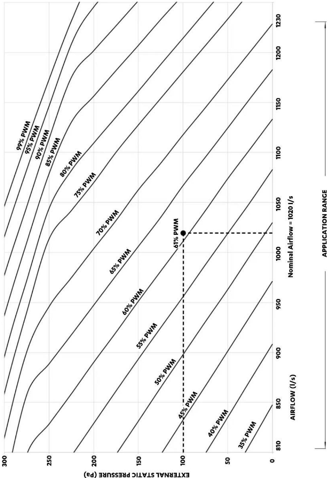
contour
| AIRFLOW (l/s) | External Static Pressure (Pa) | Power Level | | ------------- | ------------------------------ | ----------- | | 810 | 0 | 35% PWM | | 850 | 50 | 40% PWM | | 900 | 100 | 45% PWM | | 950 | 150 | 50% PWM | | 1000 | 200 | 55% PWM | | 1050 | 250 | 60% PWM | | 1100 | 300 | 65% PWM | | 1150 | 250 | 70% PWM | | 1200 | 200 | 75% PWM | | 1230 | 150 | 80% PWM | | 1230 | 100 | 85% PWM | | 1230 | 50 | 90% PWM | | 1230 | 0 | 95% PWM | | 1230 | 0 | 99% PWM |Installation and Commissioning Guide
Advance Outdoor Units
EVV240S / EFV240S
| APPLICATION RANGE (COMPRESSOR ON) * | ||||||||||||||
| AIRFLOW(l/s) | EXTERNAL STATIC PRESSURE (Pa) | |||||||||||||
| 50 100 150 | 200 250 300 350 | % PWM | W | % PWM | W | % PWM | W | % PWM | W | % PWM | W | |||
| % PWM | W | % PWM | W | |||||||||||
| 900 | 40 | 292 | 44 | 359 | 48 | 440 | 52 | 515 | 59 | 596 | 78 | 684 | 98 | 739 |
| 950 | 43 | 321 | 47 | 394 | 52 | 491 | 56 | 567 | 66 | 650 | 84 | 741 | ||
| 1000 | 47 | 365 | 51 | 441 | 55 | 522 | 59 | 606 | 73 | 707 | 93 | 794 | ||
| 1050 | 51 | 410 | 55 | 490 | 59 | 575 | 64 | 669 | 79 | 765 | 99 | 828 | ||
| 1100 | 55 | 456 | 59 | 541 | 63 | 629 | 69 | 726 | 87 | 826 | ||||
| 1130 | 57 | 485 | 62 | 579 | 66 | 673.2 | 73 | 767.6 | 92 | 861.4 | ||||
| 1150 | 59 | 504 | 63 | 592 | 68 | 703 | 76 | 795 | 96 | 885 | ||||
| 1200 | 63 | 554 | 68 | 663 | 73 | 771 | 84 | 868 | ||||||
| 1250 | 68 | 622 | 73 | 736 | 78 | 834 | 93 | 924 | ||||||
| 1300 | 73 | 692 | 78 | 810 | 84 | 912 | ||||||||
| 1350 | 78 | 762 | 83 | 882 | 92 | 970 | ||||||||
| 1360 79 | 777 | 84 | 894 | 94 | 989 | |||||||||
NOTES
* Only applicable to Third Party controllers
W = Indoor Fan Power, Watts
PWM = Pulse Width Modulation Setting, % PWM (Adjustable through the LR7-1, LC7-2, NEO or Outdoor Board).
| Default Fan Speed Value at 100 Pa | |
| Speed | Default PWM (adjustable) |
| High PWM (%) | 84 |
| Medium PWM (%) | 62 |
| Low PWM (%) | 44 |
| Indoor Fan PWM Limits | |
| High PWM Limit | 99 |
| Low PWM Limit | 39 |
Installation and Commissioning Guide
Advance Outdoor Units
EVV240S / EFV240S : Three Speed Application Fan Curve

line
| AIRFLOW (l/s) | External Static Pressure (Pa) | Label | | ------------- | ------------------------------ | --------- | | 450 | 300 | 2.34 A | | 750 | 250 | 2.73 A | | 850 | 150 | 2.65 A | | 900 | 100 | 2.47 A | | 950 | 50 | 2.28 A | | 1050 | 200 | 4.22 A | | 1100 | 150 | 4.02 A | | 1130 | 100 | 3.80 A | | 1200 | 50 | 3.57 A | | 1300 | 150 | 5.83 A | | 1350 | 100 | 5.65 A | | 1400 | 50 | 5.40 A | | Nominal Airflow = 1130 l/s | - | 44% PWM | | Nominal Airflow = 1130 l/s | - | 62% PWM | | Nominal Airflow = 1130 l/s | - | 84% PWM | | Nominal Airflow = 1130 l/s | - | - || Hi-Mid-Low Speed Airflow Range | |
| Variable Fan Technology Airflow Range | |
Installation and Commissioning Guide
Advance Outdoor Units
EVV240S / EFV240S : Third Party Application Fan Curve

Installation and Commissioning Guide
Advance Outdoor Units
Refrigerant Charging
- The unit is supplied with factory charged refrigerant as stated in the Rating Label. The use other material as a refrigerant may cause explosion and/or personal injury.
- Be aware of all the relevant regulations concerning the handling of refrigerant.
- The system of this unit operates with Polyester (POE) ^* oil.
- It is important to work with absolute cleanliness.
- Brazing must be done with the use of Nitrogen to avoid carbon deposits into the pipes.
- The system must be evacuated thoroughly to 500 microns (see evacuation procedure).
- Never allow refrigerant to vent into the atmosphere. It is an offence to release refrigerant in Australia.
• Always reclaim refrigerant using equipment and container dedicated for the refrigerant used in the system. - Only qualified technicians are allowed to perform any work described in this guide.
- All work must be carried out in accordance with Australia and New Zealand refrigerant handling code of practice.
Charging Method: Subcooling and Superheat
Parameters:
LLT = Liquid Line Temperature
SLT = Suction Line Temperature
SCT = Saturated Condensing Temperature
SST = Saturated Suction Temperature
Cooling and Heating Operation:
Adjust the refrigerant charge to obtain the correct super heat and sub-cool for optimal performance as follows:
- Ensure that air filters are fitted and total system airflows are achieved. (Air filters are not supplied with the unit, it is the responsibility of the installing contractor to provide and fit adequate return air and fresh air filters).
- Connect service gauges to the shut off valves.
- Start the unit in cool mode ensuring that the compressor is in operation before taking service gauges reading. Allow the system to stabilise for next 15 - 30 minutes before recording.
- Record the discharge pressure, suction pressure, liquid line temperature and suction line temperature for all the refrigeration circuits.
Discharge Pressure = ____ kPa Suction Pressure = ____ kPa
Liquid Line Temperature (LLT) = ____°C
Suction Line Temperature (SLT) = ____ °C
Installation and Commissioning Guide
Advance Outdoor Units
NOTES
- Accurate pressure and temperature measuring tools should be used to achieve satisfactory results.
- The sensors of thermocouple must be in good contact with the area being measured and must be insulated in order to obtain correct reading.

Checking for Subcooling
- From the Pressure / Temperature Chart, record the corresponding Saturated Condensing Temperature (SCT) at the given discharge pressure.
- Calculate the system subcooling using the formula below:
Subcooling = SCT - LLT
-
If subcooling is within the range (see charging table), there is no need to add/remove refrigerant.
-
If subcooling is lower than minimum, the system is undercharged, it is necessary to add refrigerant.
- If subcooling is higher than maximum, the system is overcharged, it is necessary to remove refrigerant.
Allow the systems to stabilise (15 - 30 mins) and repeat the steps 1-3 until subcooling falls within the range specified in the Subcooling/Superheat Table below.
Installation and Commissioning Guide
Advance Outdoor Units
Checking for Superheat
Maintaining the correct superheat is important for ensuring the evaporator is achieving maximum capacity and avoiding excessive liquid refrigerant returning to the compressor.
- From the Pressure/Temperature Chart, record the corresponding Saturated Suction Temperature (SST) at the given suction pressure.
- Calculate the system super heat using the formula below:
Superheat = SLT -SST
-
If superheat is within the range (see charging table), there is no need to add/remove refrigerant.
-
If superheat is lower than minimum, it means that liquid refrigerant may be returning to compressor. It is necessary to remove refrigerant or check EEV settings.
- If superheat is higher than maximum, it means that refrigeration capability of evaporator is not fully maximised. It is necessary to add refrigerant charge or check EEV settings.
Allow the systems to stabilise (15 - 30 mins) and repeat the steps 1-3 until superheat falls within the range specified in the table below.
| Subcooling/Superheat Table | |||
| Cooling Heating | |||
| Subcooling Superheat Subcooling Superheat | |||
| 4 - 8 2 - 8 10 | - 14 2 - 8 | ||
NOTES
The above subcooling and superheat recommendations are based on the following rated conditions:
• Cooling: 35 °C DB outdoor, air entering indoor at 27°C DB / 19°C WB.
- Heating: 7 ^ C DB / 6 ^ C WB outdoor, air entering indoor at 20 ^ C DB Nominal indoor airflow.
CHARGING TABLE
Installation and Commissioning Guide
Advance Outdoor Units
| Temp°C | Pressure KPa | Temp°C | Pressure KPa | Temp°C | Pressure KPa | Temp°C | Pressure KPa |
| -50 9 | -19 320 | 11 1040 | 41 2439 | ||||
| -49 15 | -18 336 | 12 1073 | 42 | 2500 | |||
| -48 20 | -17 353 | 13 1108 | 43 | 2564 | |||
| -47 27 | -16 369 | 14 1143 | 44 | 2628 | |||
| -46 33 | -15 387 | 15 1180 | 45 | 2694 | |||
| -45 40 | -14 405 | 16 1217 | 46 | 2760 | |||
| -44 46 | -13 424 | 17 1255 | 47 | 2829 | |||
| -43 54 | -12 442 | 18 1293 | 48 | 2898 | |||
| -42 61 | -11 462 | 19 1333 | 49 | 2969 | |||
| -41 69 | -10 481 | 20 1373 | 50 | 3040 | |||
| -40 76 | -9 502 | 21 1415 | 51 3114 | ||||
| -39 85 | -8 523 | 22 1457 | 52 3187 | ||||
| -38 93 | -7 545 | 23 1501 | 53 3264 | ||||
| -37 102 | -6 567 | 24 1544 | 54 | 3340 | |||
| -36 111 | -5 590 | 25 1589 | 55 3419 | ||||
| -35 121 | -4 613 | 26 1634 | 56 | 3498 | |||
| -34 130 | -3 637 | 27 1681 | 57 | 3580 | |||
| -33 140 | -2 661 | 28 1728 | 58 | 3662 | |||
| -32 150 | -1 687 | 29 1777 | 59 3747 | ||||
| -31 161 | 0 712 | 30 1826 | 60 | 3832 | |||
| -30 172 | 1 739 | 31 1877 | 61 3920 | ||||
| -29 184 | 2 765 | 32 1928 | 62 | 4008 | |||
| -28 195 | 3 793 | 33 1981 | 63 | 4099 | |||
| -27 208 | 4 821 | 34 | 2034 | 64 | 4190 | ||
| -26 220 | 5 851 | 35 | 2089 | 65 | 4284 | ||
| -25 234 | 6 880 | 36 2144 | 66 | 4378 | |||
| -24 247 | 7 | 911 | 37 2201 | 67 | 4476 | ||
| -23 261 | 8 941 | 38 2258 | 68 | 4573 | |||
| -22 275 | 9 | 974 | 39 2318 | 69 | 4675 | ||
| -21 290 | 10 | 1006 | 40 | 2377 | 70 | 4776 | |
| -20 304 |
Installation and Commissioning Guide
Advance Outdoor Units
Maintenance
Maintenance Procedures
This section describes the procedures that must be performed as a part of normal maintenance program. Regular servicing of equipment by licensed technician is highly recommended. Regular servicing of your unit helps in maintaining its optimum performance and reliability. The checklist and service periods provided on this manual are guides only, as some sites may require more frequent servicing. Always disconnect electrical power to the unit before performing these procedures. It is always a safe practice to observe all safety warnings and cautions when conducting maintenance tasks.

DANGER
Live Electrical Connections!
It may be necessary to work with live electrical components on certain maintenance tasks. Only licensed electricians and qualified technicians are allowed to perform these tasks.
Beware of Rotating Fan Blades!
Always make sure that all power supply to the Fans are turn Off and isolated.
Observe WH&S safety procedures, do not wear loose clothing and any jewellery when working near the fans.
Wear PPE whenever performing any maintenance procedures.
Observe all necessary procedures when working on a confined space.

WARNING
Hazardous Voltage!
Always make sure that all power supply, including remote controls, are disconnected before performing maintenance. Observe proper LOCK-OUT/TAG-OUT procedures to ensure that power cannot be inadvertently energised. Failure to disconnect power before maintenance procedures can result in serious injury and/or death.
EC Motors are fitted with high power capacitors and can have dangerous residual voltages at motor terminals after power has been isolated. Wait at least 5 minutes after power isolation and test for any residual voltage before beginning service work.
Annual Maintenance Checklists
- Perform general maintenance inspections.
- Perform scheduled start-up checks.
- Leak test refrigerant circuits.
- Inspect contacts of all contactors and relays. Replace all worn contacts as required.
- Inspect, clean and tighten all electrical connections.
- Inspect the air filters, clean or replace as required.
- Clean and repaint any corroded panel section.
- Ensure no blockage of airflow through variable speed drive.
- Check fans for balanced operation. Make sure that there are no loose screws / bolts, no fan blades interference and no damage to the fans and guards.
Cleaning the Condenser Coils
Clean the coils at least once a year or more frequently if unit is located in a dusty and dirty environment, in order to maintain your system's proper operating performance. High discharge pressures are good indication that the coils need cleaning. When using detergent or solvents to clean the coils, follow the manufacturer's instructions to avoid potential damage to the coils and to the unit.
To clean the refrigerant coils, use a soft brush and water spray, such as garden hose or pressure washer with low pressure nozzle.
Installation and Commissioning Guide
Advance Outdoor Units

WARNING
Do Not Use High Alkaline Detergent!
When using detergent for coil cleaning, ensure that the alkaline level is no higher than 8.5, which can cause corrosion damage to the coils.

DANGER
No Water into the Electrical Compartments!
Ensure consideration is given to the possibility of water entering the electrical compartments during cleaning of the condenser coil.
Coil Cleaning Procedures
- Disconnect power to the unit.
- Remove the louvered panels from the unit to gain access to the air inlet side of the coils.
- Use a soft brush to remove loose dirt and debris from both sides of the coils.
- Straighten bent coil fins with fin comb.
- Prepare the detergent solutions according to the manufacturer's instructions.
- Spray solution at a 90^ angle to the coils, keeping a minimum nozzle spray angle of 15^ , with at least a 1800mm distance from the coils and 600 psi pressure.
- Spray leaving air side of the coils first then the air inlet side. Allow the solution to stand on the coils for five minutes.
- Rinse both sides of the coils with cool clean water.
- Inspect the coils, if they are still dirty, repeat the cleaning procedure.
- Clean and wipe dry the outer and inner sides of the unit, the refrigerating parts and other components.
- Ensure that the condensate drain lines are not blocked.
- Reinstall all unit panels, covers and guards.
- Restore electrical power to the unit.
Installation and Commissioning Guide
Advance Outdoor Units
Maintenance Frequency Checklist
Regular servicing of equipment by a qualified technician is recommended every 12 months for residential applications and every quarter for commercial applications. Regular servicing of your unit helps in maintaining its optimum performance and reliability. The following checklist and service periods are provided as a guide only, as some sites may require more frequent servicing.
| ELECTRICAL | ||||||||||
| Parts | Service Period | Detail of Service Check Service Methods | ||||||||
| 1 Mth | 3 Mth | 6 Mth | 1 Yr | 2 Yrs | 3 Yrs | 4 Yrs | 5 Yrs | |||
| Printed Circuit Boards | √ | Visual Inspection | Tighten Terminals as necessary on printed circuit boards | |||||||
| Electrical Connections | √ | Check all electrical terminals, mains, communications, etc | Re-tighten if loose. | |||||||
| OUTDOOR UNIT | ||||||||||
| Parts | Service Period | Detail of Service Check Service Methods | ||||||||
| 1 Mth | 3 Mth | 6 Mth | 1 Yr | 2 Yrs | 3 Yrs | 4 Yrs | 5 Yrs | |||
| Casing / Panels and Frames | √ | Visual check for damage, rust and dust accumulation. | For highly corrosive environment, wash panels quarterly with water and neutral detergent solution. Wax panels. Repair / re-paint where required. | |||||||
| Insulation | √ | Visual check for insulation conditions. | Repair / replace insulation material. | |||||||
| Fan | √ | Visual check for run out of balance and dust attached | Clean off dust as necessary to negate possibility of fan running out of balance | |||||||
| Motor | √Ω | Visual check on wiring. Insulation resistance check to be carried out annually | Measure insulation resistance. Should be more than 1MΩ | |||||||
| Heat Exchanger | √ | Check for clogging by dust. Check for leaks / damage. | Clean air inlet side as necessary. Straighten any bent fins using fins comb. | |||||||
| Condensate Drain Line (if available) | √ | Check for obstructions and free flow of water | Clean to eliminate obstructions/ sludge and check condition of drain line. Pour water to ensure free flow. | |||||||
| Compressor | √Ω | Check for high / low pressure. Measure insulation resistance. Check compressor for abnormal noise/vibrations | Measure insulation resistance. Should be more than 1MΩ. | |||||||
| Refrigeration Operational Readings | √ | Make note of operational reading in test cool/heat | Check operating pressures, record superheat and subcooling values | |||||||
| Safety Devices | √ | Check calibration of safety devices such as HP and LP controls, sensors, etc | Check resistance of sensors, pressure cut in / cut out of pressure controls | |||||||
| Faults | √ | Check for any previous fault history on unit. | Investigate any causes for previous faults, reset fault history. | |||||||
Installation and Commissioning Guide
Advance Outdoor Units
Start Up and Commissioning Report
| INSTALLATION INFORMATION | ||
| CUSTOMER | Name: Tel. Number: | |
| Address: | ||
| INSTALLER | Name: Tel. Number: | |
| Address: | ||
| Site Address: Date Installed: | ||
| Model: Serial Number: | ||
| CIRCUIT TEMPERATURE SETTINGS | ||
| Supply Air Temperature | °C | |
| Return Air Temperature | °C | |
| Suction Temperature | °C | |
| Discharge Temperature | °C | |
| Condenser Coil Temperature | °C | |
| Ambient Temperature | °C | |
| INDOOR FAN SETTINGS OUTDOOR FAN SETTINGS | |||
| Indoor Fan Current Amps | Outdoor Fan Current Amps | ||
| Indoor Fan Airflow l / s | |||
| Indoor Fan PWM % | |||
| Set Static Pa | |||
| Check No Active Error Codes on the Unit Checked: |
| Date Checked: |
Installation and Commissioning Guide
Advance Outdoor Units
Installation and Commissioning Guide
Advance Outdoor Units
Installation and Commissioning Guide
Advance Outdoor Units

ActronAir
That's better. That's Action.
actronair.com.au
1300 522 722
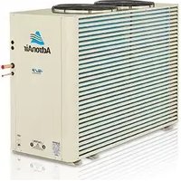
- ADVANCE Split Ducted Unit
- IMPORTANT NOTE:
- Table of Contents
- Installation and Commissioning Guide
- Advance Outdoor Units
- Indoor Fan Commissioning 42
- Refrigerant Charging 57
- Maintenance 61
- Maintenance Frequency Checklist 63
- Start Up and Commissioning Report 64
- Introduction
- Information About This Guide
- NOTE
- Product Inspections
- Codes, Regulations And Standards
- General Information
- Energy Efficient Refrigeration Circuits
- Evaporator Section
- Condenser Section
- Electrical Section
- Durable Design and Construction
- System Flexibility
- Refrigerant Handling and Accountability
- Sustainability and Environmentally Friendly
- Safety Instructions
- DANGER
- Hazardous Voltage - Risk of Electrocution.
- WARNING
- CAUTION
- Beware of Rotating Fans!
- VISUAL INSPECTION AND WORK ASSESSMENT
- Installation Information
- Recover and Recycle Refrigerants
- Refrigerant Handling and Safety
- Service Equipment and Recovery Procedures
- INSTALLATION PREPARATION (Pre-Installation considerations)
- For units charged with R-410A
- For units charged with R-32
- Operation Manual Access
- Download from website
- Control Panel
- Unit Dimensions and Clearances
- NOTES:
- Unit Lifting Procedure
- Crane Lifting Method
- Equipment Required For Crane Lifting:
- Procedure:
- Fork Lift Method
- Outdoor Unit Preparation
- Field Pipe Connection
- Piping and Brazing
- This outdoor unit described in this guide is designed to match only with an ActronAir indoor unit as specified in the Technical Selection Catalogue.
- Installing interconnecting pipe work to indoor, nitrogen bleed procedure (First fit or rough in stage only)
- Installing interconnecting pipe work to outdoor, nitrogen bleed procedure (First fit or rough in stage only)
- Pressure Testing
- NOTES
- Importance of Evacuation:
- Evacuation Procedure (Triple Evacuation)
- Electrical Installation
- Live Electrical Supply!
- STATIC SENSITIVE ELECTRONIC DEVICES!
- Wiring Diagram
- Supply and Power Requirements Procedure
- Compressor Voltage Balance Requirement
- Crankcase Heater
- Electrical Connection
- DETAILED WIRING DIAGRAM IS PROVIDED WITH THE UNIT.
- Split Unit
- Data Cable Shielding Instructions
- Wall Controller Options
- Wiring Configuration : Recommended
- Wiring Connections
- NEO Wall Control Wiring Connections
- LM-RS-2 Optional Sensor Wiring Connections
- REMOTE SENSOR WIRING
- NOTE:
- AERSS Optional Duct Sensor Wiring Connections
- Demand Response Management
- Configuring and Commissioning Setup
- MENU
- ENTER
- BACK
- Configuring Compressor and Capacity(cnFg)
- Configuring Control Source (CtrS)
- Third Party Control
- Wall Control
- Basic BMS
- Wall Control + Basic BMS
- Advanced BMS
- Auto Fan Function
- Third Party Control Input (Indoor and/or Outdoor Board)
- 0-10V Analogue Input for Compressor and Indoor Fan
- 0-10V Analogue Input for Compressor with Fixed Indoor Fan Speed
- Input for Fixed Compressor with Fixed Indoor Fan Speed
- 0-10V Analogue Input for Indoor Fan with Fixed Speed Compressor
- Run and Fault Indication Output (Outdoor Board)
- Remote On/Off
- Indoor Fan Commissioning
- EVV160S / EFV160S
- EVV240S / EFV240S
- Refrigerant Charging
- Charging Method: Subcooling and Superheat
- Parameters:
- Cooling and Heating Operation:
- Checking for Subcooling
- Checking for Superheat
- Superheat = SLT -SST
- Maintenance
- Maintenance Procedures
- Live Electrical Connections!
- Beware of Rotating Fan Blades!
- Hazardous Voltage!
- Annual Maintenance Checklists
- Cleaning the Condenser Coils
- Do Not Use High Alkaline Detergent!
- No Water into the Electrical Compartments!
- Coil Cleaning Procedures
- Maintenance Frequency Checklist
- ActronAir
Brand : ActronAir
Model : CRV240T
Category : Air Conditioning