ITC-300 - Intercom DataVideo - Free user manual and instructions
Find the device manual for free ITC-300 DataVideo in PDF.


User questions about ITC-300 DataVideo
0 question about this device. Answer the ones you know or ask your own.
Ask a new question about this device
Download the instructions for your Intercom in PDF format for free! Find your manual ITC-300 - DataVideo and take your electronic device back in hand. On this page are published all the documents necessary for the use of your device. ITC-300 by DataVideo.
USER MANUAL ITC-300 DataVideo
natural_image
Line drawing of a data video container with ports and control buttons (no text or symbols on the device body)DIGITAL
INTERCOM SYSTEM
ITC-300
Instruction Manual
Table of Contents
TABLE OF CONTENTS 2
FCC COMPLIANCE STATEMENT 4
WARNINGS AND PRECAUTIONS 4
WARRANTY 5
STANDARD WARRANTY....5
THREE YEAR WARRANTY 6
DISPOSAL 6
PRODUCT OVERVIEW 8
FEATURES 8
SYSTEM DIAGRAM 9
SYSTEM OVERVIEW....11
BASE UNIT....11
REAR PANEL 13
BELT PACK....15
RJ-1M Protective Shield.... 16
Control Panel.... 16
DEVICE PAIRING PROCEDURE.... 18
Check the Belt Pack's Paired Channel with the Base Unit 19
Clearing Channel Assignment.... 19
Noise Reduction....20
FUNCTION KEYS....21
CHECK THE BELT PACK'S CHANNEL ASSIGNMENT 21
GROUP COMMUNICATION 21
ALL COMMUNICATION 21
CROSS COMMUNICATION (PARTY MODE) 22
HOW TO OPERATE THE BASE UNIT TO COMMUNICATE WITH UP TO 4 BELT PACKS
SIMULTANEOUSLY UNDER PARTY MODE 23
AUDIO IN....24
Disclaimer of Product & Services
The information offered in this instruction manual is intended as a guide only. At all times, Datavideo Technologies will try to give correct, complete and suitable information. However, Datavideo Technologies cannot exclude that some information in this manual, from time to time, may not be correct or may be incomplete. This manual may contain typing errors, omissions or incorrect information. Datavideo Technologies always recommend that you double check the information in this document for accuracy before making any purchase decision or using the product. Datavideo Technologies is not responsible for any omissions or errors, or for any subsequent loss or damage caused by using the information contained within this manual. Further advice on the content of this manual or on the product can be obtained by contacting your local Datavideo Office or dealer.
FCC Compliance Statement
This device complies with part 15 of the FCC rules. Operation is subject to the following two conditions:
(1) This device may not cause harmful interference, and
(2) This device must accept any interference received, including interference that may cause undesired operation.
Warnings and Precautions
- Read all of these warnings and save them for later reference.
- Follow all warnings and instructions marked on this unit.
- Unplug this unit from the wall outlet before cleaning. Do not use liquid or aerosol cleaners. Use a damp cloth for cleaning.
- Do not use this unit in or near water.
- Do not place this unit on an unstable cart, stand, or table. The unit may fall, causing serious damage.
- Slots and openings on the cabinet top, back, and bottom are provided for ventilation. To ensure safe and reliable operation of this unit, and to protect it from overheating, do not block or cover these openings. Do not place this unit on a bed, sofa, rug, or similar surface, as the ventilation openings on the bottom of the cabinet will be blocked. This unit should never be placed near or over a heat register or radiator. This unit should not be placed in a built-in installation unless proper ventilation is provided.
- This product should only be operated from the type of power source indicated on the marking label of the AC adapter. If you are not sure of the type of power available, consult your Datavideo dealer or your local power company.
- Do not allow anything to rest on the power cord. Do not locate this unit where the power cord will be walked on, rolled over, or otherwise stressed.
- If an extension cord must be used with this unit, make sure that the total of the ampere ratings on the products plugged into the extension cord do not exceed the extension cord rating.
- Make sure that the total amperes of all the units that are plugged into a single wall outlet do not exceed 15 amperes.
- Never push objects of any kind into this unit through the cabinet ventilation slots, as they may touch dangerous voltage points or short out parts that could result in risk of fire or electric shock. Never spill liquid of any kind onto or into this unit.

-
Except as specifically explained elsewhere in this manual, do not attempt to service this product yourself. Opening or removing covers that are marked "Do Not Remove" may expose you to dangerous voltage points or other risks, and will void your warranty. Refer all service issues to qualified service personnel.
-
Unplug this product from the wall outlet and refer to qualified service personnel under the following conditions:
a. When the power cord is damaged or frayed;
b. When liquid has spilled into the unit;
c. When the product has been exposed to rain or water;
d. When the product does not operate normally under normal operating conditions. Adjust only those controls that are covered by the operating instructions in this manual; improper adjustment of other controls may result in damage to the unit and may often require extensive work by a qualified technician to restore the unit to normal operation;
e. When the product has been dropped or the cabinet has been damaged;
f. When the product exhibits a distinct change in performance, indicating a need for service.
Warranty
Standard Warranty
- Datavideo equipment is guaranteed against any manufacturing defects for one year from the date of purchase.
- The original purchase invoice or other documentary evidence should be supplied at the time of any request for repair under warranty.
- The product warranty period beings on the purchase date. If the purchase date is unknown, the product warranty period begins on the thirtieth day after shipment from a Datavideo office.
- All non-Datavideo manufactured products (product without Datavideo logo) have only one year warranty from the date of purchase.
- Damage caused by accident, misuse, unauthorized repairs, sand, grit or water is not covered under warranty.
- Viruses and malware infections on the computer systems are not covered under warranty.
- Any errors that are caused by unauthorized third-party software installations, which are not required by our computer systems, are not covered under warranty.
- All mail or transportation costs including insurance are at the expense of the owner.
- All other claims of any nature are not covered.
- All accessories including headphones, cables, batteries, metal parts, housing, cable reel and consumable parts are not covered under warranty.
- Warranty only valid in the country or region of purchase.
- Your statutory rights are not affected.
Three Year Warranty

- All Datavideo products purchased after July 1st, 2017 qualify for a free two years extension to the standard warranty, providing the product is registered with Datavideo within 30 days of purchase.
- Certain parts with limited lifetime expectancy such as LCD panels, DVD drives, Hard Drive, Solid State Drive, SD Card, USB Thumb Drive, Lighting, Non-PCIe Card and third party provided PC components are covered for 1 year.
- The three-year warranty must be registered on Datavideo's official website or with your local Datavideo office or one of its authorized distributors within 30 days of purchase.
Disposal

natural_image
Symbol of a trash bin crossed with diagonal lines, no text or labels presentFor EU Customers only - WEEE Marking
This symbol on the product or on its packaging indicates that this product must not be disposed of with your other household waste. Instead, it is your responsibility to dispose of your waste equipment by handing it over to a designated collection point for the recycling of waste electrical and electronic equipment. The separate collection and recycling of your waste equipment at the time of disposal will help to
conserve natural resources and ensure that it is recycled in a manner that protects human health and the environment. For more information about where you can drop off your waste equipment for recycling, please contact your local city office, your household waste disposal service or the shop where you purchased the product.
CE
CE Marking is the symbol as shown on the left of this page. The letters "CE" are the abbreviation of French phrase "Conformité Européenne" which literally means "European Conformity". The term initially used was "EC Mark" and it was officially replaced by "CE Marking" in the Directive 93/68/EEC in 1993. "CE Marking" is now used in all EU official documents.
Product Overview
The Datavideo ITC-300 Digital Intercom System is an 8-channel wired communication system, allowing direct connections of up to 8 belt packs. With the ITC-300, the director will then be able to speak to the team crews located at different sites either simultaneously or individually.
The ITC-300 is a standard 19" 1U rack design which facilitates integration of the device into any rack system for use in the field or studio. It can also be used with other various switcher models designed and manufactured by Datavideo such as the SE-500HD, SE-650, SE-2200, SE-2850 and SE-3200.
Features
Front Panel
• Composite XLR / ¼" (6.3mm) Microphone Input Jack
- Condenser and Dynamic Gooseneck Microphone switch
(Complete package includes Gooseneck Microphone and USB LED Lamp)
- 14'' (6.3mm) Stereo Headphone Socket
• 3.5mm Stereo Socket for Microphone Headset
• Built-in speaker with volume control
- Channel buttons 1 – 8 for individual channel paging and communication
- Simultaneous ALL channel communication
- Mute button to shut down the device audio
Rear Panel
• Supports 8-Way digital wired Intercom via Ethernet cables
- Extension of Communication distance up to 100 meters
• Two 15-pin DSub tally input ports for receiving tally signals sent from switchers
ITC-300SL Belt Pack
- High mobility
- Call button for paging the system intercom
• Talk button for establishing communication with the system intercom
• Headphone volume control - Bi-color tally light indicator
- Connects TD-2/3 tally light indicator installed on the camera
System Diagram
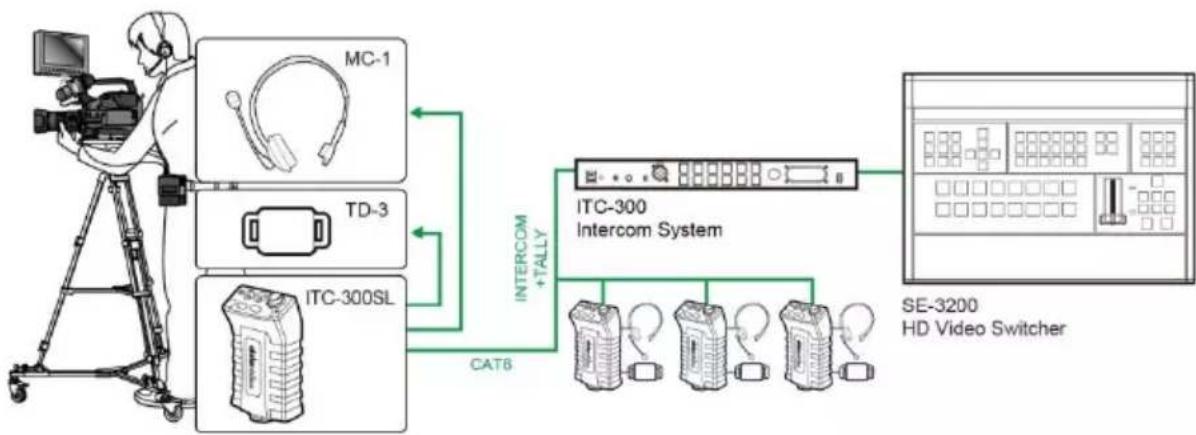
The first system diagram basically provides an illustration of how the ITC-300 Digital Intercom System can be set up in a switcher production environment.
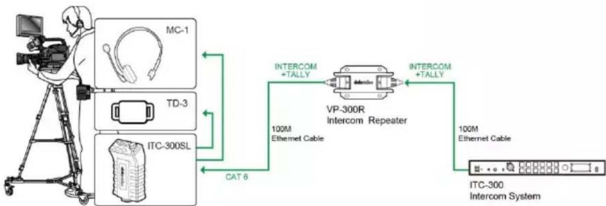
The second system diagram shows you how to connect the VP-300R Intercom Repeater between the ITC-300 Digital Intercom System and the ITC-300SL Digital Intercom Belt Pack.
The ITC-300 Interfacing the SE-3200 HD Video Switcher via Tally Inputs
flowchart
graph LR
    A["Monitor"] --> B["MC-1"]
    A --> C["TD-3"]
    A --> D["ITC-300SL"]
    B --> E["Intercom System"]
    C --> E
    D --> E
    E --> F["HD Video Switcher"]
    style A fill:#f9f,stroke:#333
    style F fill:#ccf,stroke:#333
The VP-300R Intercom Repeater Interfacing between the ITC-300 and the ITC-300SL
flowchart
graph LR
    A["Camera"] --> B["MC-1"]
    A --> C["TD-3"]
    A --> D["ITC-300SL"]
    B --> E["Intercom +TALLY"]
    C --> E
    D --> E
    E --> F["VP-300R Intercom Repeater"]
    F --> G["100M Ethernet Cable"]
    F --> H["100M Ethernet Cable"]
    G --> I["ITC-300 Intercom System"]
    H --> I
    D --> J["CAT 6"]
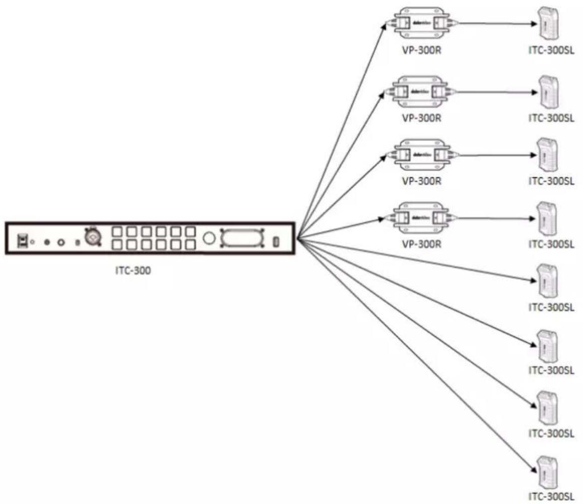
Note: When all eight channels of the ITC-300 base unit are occupied with the ITC-300SL belt pack, only 4 of the 8 belt packs can be simultaneously connected of the VP-300R Intercom Repeater. See the diagram below.
flowchart
graph TD
    A["ITC-300"] --> B["VP-300R"]
    A --> C["VP-300R"]
    A --> D["VP-300R"]
    A --> E["VP-300R"]
    B --> F["ITC-300SL"]
    C --> G["ITC-300SL"]
    D --> H["ITC-300SL"]
    E --> I["ITC-300SL"]
    B --> J["ITC-300SL"]
    C --> K["ITC-300SL"]
    D --> L["ITC-300SL"]
    E --> M["ITC-300SL"]
System Overview
This chapter contains introductory guides to operations on the front panel and connections at the rear.
Base Unit

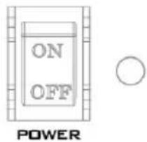
On/Off Switch
Powers the ITC-300 On / Off. Red LED indicates that unit is switched on.
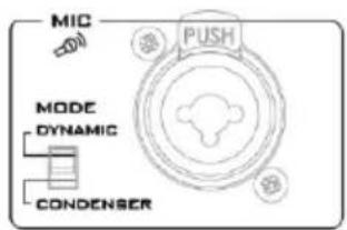
XLR Microphone Socket
Composite XLR / 1/4" (6.3mm) Microphone Input Jack for either a Condenser or Dynamic Gooseneck Microphone.
- XLR supports Condenser Gooseneck Microphones (Supplied).

Headphone Socket
14 " (6.3mm) Stereo Headphone Socket for conventional headphones.
Note: Plugging in headphones will disable the built-in speaker.

Microphone / Headset Socket
3.5mm Stereo Socket for Microphone Headset.
Note: Plugging in a Microphone Headset will disable the built-in speaker.

ALL Button
Opens communication with all channels.
Note: All channels will hear communication from the operator by pressing the ITC-300SL Belt Pack's TALK button.

HOLD Button
Press the HOLD button to check available online belt packs and select channels for group communication.
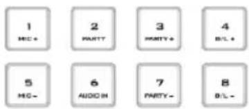
Channel Buttons 1 - 8
Opens communication with individual channels. More than 1 channel can be active at any given time, and active channels are illuminated red.
All active channels will hear communication from the operator. The buttons will also indicate if any channel is paging, the paging channel will flash in green until the page is answered.
These channel buttons can also be used to gain access to certain built-in features on the ITC-300. See the section on Function Keys for details.

Mute Button
Mutes all communications from the base station.
NOTE: If any channel user presses the belt pack's CALL button, that particular channel button on the base unit's front panel will start flashing.

SHIFT Button
Press the SHIFT button to adjust the microphone's audio level, the belt pack's volume in the PARTY mode and enable/disable AUDIO IN mode.

natural_image
Pure diagram of an oval shape with four corner markers (no text or symbols)Volume Control
Controls the volume of the built-in speaker or audio output to the headphone or MIC headset (whichever is connected).
Built-In Speaker
Sounds audible alert when a channel is paging and provides audio during talkback conversations.
Note: Speaker is disabled when headphone or MIC headset is connected to the ITC-300.

USB Light Socket
For powering the connected USB gooseneck light (supplied).
Rear Panel
The ITC-300 is a standalone model supporting 8 channel communication. It also powers the belt pack directly.


Belt Pack Channel Ports
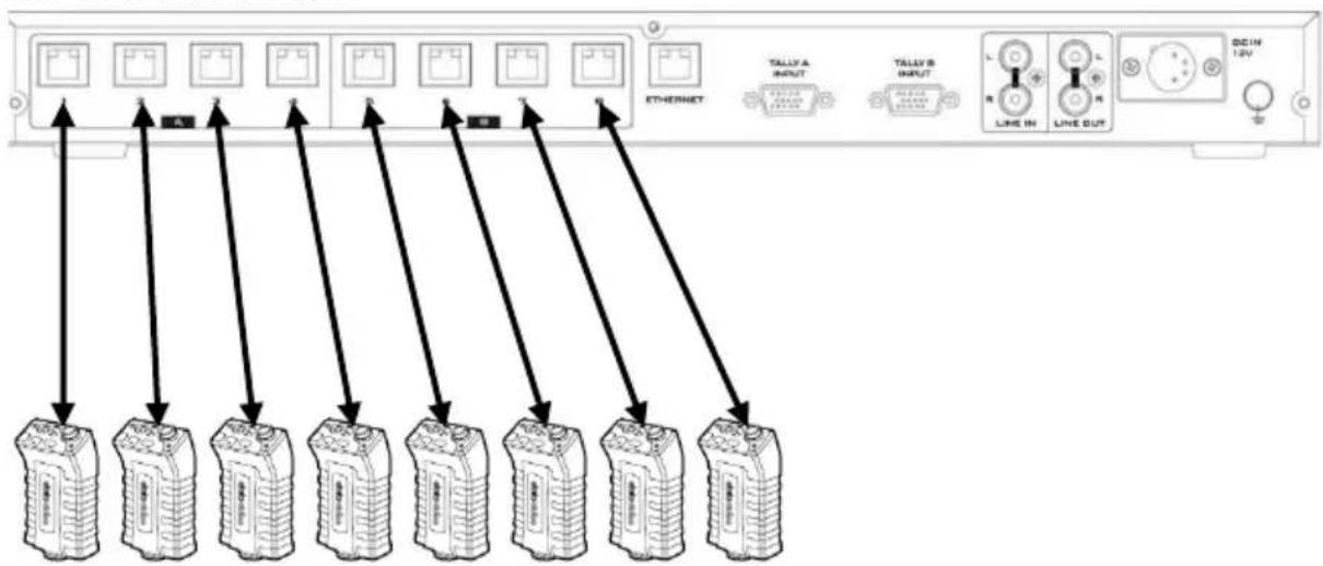
Each of the 8 channels has an Ethernet connector that carries bi-directional signals between the ITC-300 and the ITC-300SL. Power, tally and bi-directional audio are all carried though the same Ethernet cable (supplied).
After connecting the ITC-300SL to the Ethernet port, the belt pack must be paired to the corresponding channel button of the ITC-300. See the section on Pairing Procedure for details.
Note: The product package contains a base unit and four belt packs which are already paired before shipment. You are allowed to connect additional belt packs but they must be paired with the base unit prior use.
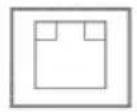
ETHERNET
Ethernet Port
For FW Upgrade. See the Firmware Update section.
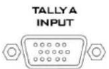
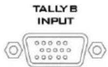
Tally Inputs A / B
Tally Inputs A & B provide direct connection to the Datavideo switcher. They supply bi-color tally information to the ITC-300SL; RED indicates Live and GREEN indicates Cued.
Tally Input A carries bicolor tally information of Channels 1 \~ 4 and Tally Input B carries bicolor tally information of Channels 5 \~ 8.
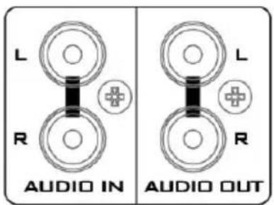
Audio IN/OUT
Audio IN/OUT
Connects an external audio source to AUDIO IN and the AUDIO OUT outputs the internal audio.
See the section on AUDIO IN mode for connection methods.
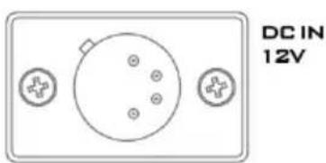
DC Power IN
DC in socket connects the supplied 12V / 36W PSU.

Ground Terminal
When connecting this unit to any other component, make sure that it is properly grounded by connecting this terminal to an appropriate point. When connecting, use the socket and be sure to use wire with a cross-sectional area of at least 1.0 mm ^2 .
Belt Pack
As shown in the diagram below, before use, connect the belt pack's communication port located at the opposite end of the control panel to the base unit's belt pack channel ports with an Ethernet cable.
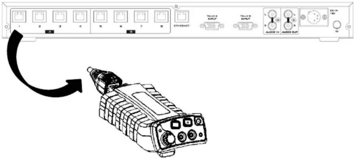
Note: Please only use CAT6 23AWG Ethernet cable or above.
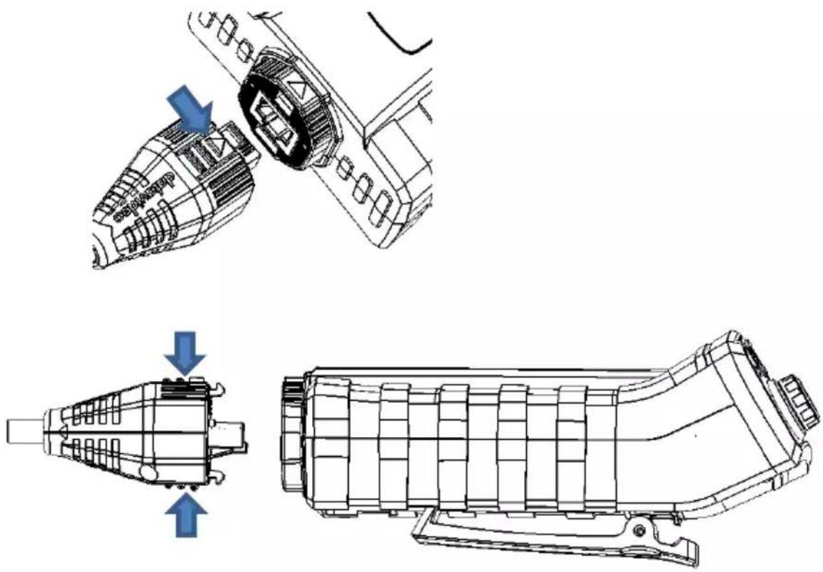
To disconnect the Ethernet cable from the belt pack, press and hold the parts indicated by the arrows as shown in the diagram below then gently pull out the RJ-45 connector.
natural_image
Technical line drawings of mechanical components, showing exploded and assembled views (no text or symbols)RJ-1M Protective Shield
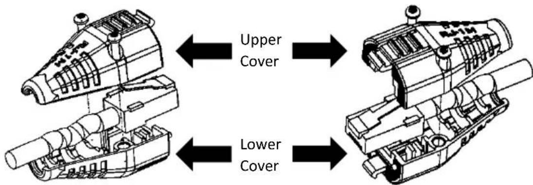
RJ-1M is a protective shield supplied by Datavideo for protecting the RJ-45 connector of the Ethernet cable. As depicted in the diagram below, place the RJ-45 connector between the upper and lower covers of the RJ-1M then secure the covers with two screws.
The subsequent section provides introductory guides to operations using the belt pack's control panel.
Control Panel
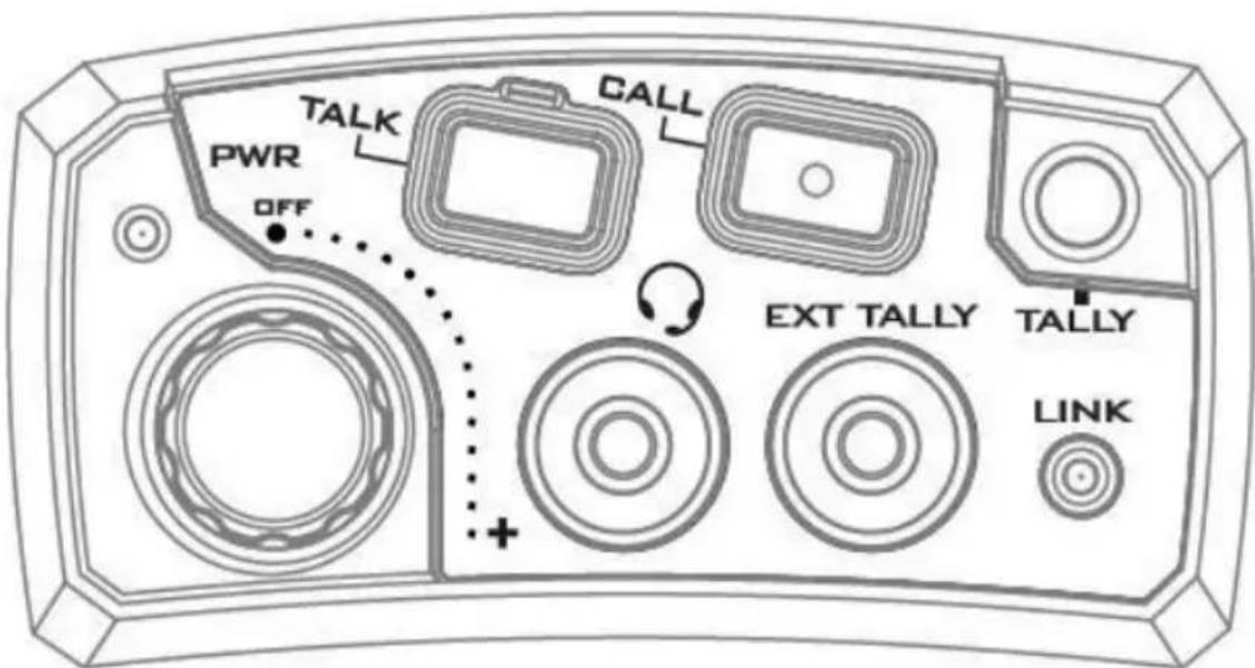
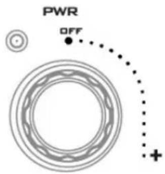
Power Switch / Audio Control knob
Turn clockwise (towards +) to turn ON the power. Turn anti-clockwise (towards OFF) to turn OFF the power.
The Power LED will be turned ON when the belt pack is powered ON.
Adjusts the volume of the MIC / headset connected to the MIC / Headphone Socket. Turn anti-clockwise (towards OFF) to lower the volume, and clockwise (towards +) to increase the volume.

Link LED Indicator
Illuminates YELLOW when the ITC-300SL belt pack has established connection with the ITC-300 base unit.

MIC / Headphone Socket
The ITC-300SL has both a 3.5mm MIC socket. The user is allowed to use a standard 3.5mm MIC / Headset.
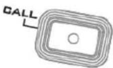
Call Button
Sends a paging message to the ITC-300 Base Unit. The base unit's channel button will flash green and there will be an audible tone each time the button is pressed.
When the LED indicator illuminates red, it indicates that the belt pack is sending audio to the Base Unit. When the LED indicator illuminates green, it indicates that the belt pack is receiving audio from the Base Unit.
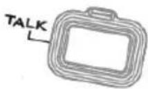
Talk Button
Opens up talkback communication with the ITC-300 Base Unit.

External Tally LED Socket
An external tally LED (TD-2/3) can be connected to the ITC-300SL via a GPI cable. This enables the tally light to be positioned in a more visible place, such as on top of the camera. When the channel is LIVE, the LED will be RED, and when the channel is CUED, the LED will be GREEN.
NOTE: The Tally LED on the ITC-300SL will continue to operate as normal even after a TD-2/3 has been connected.

Bi-Color Tally LED
Illuminates RED when the channel is LIVE and GREEN when the channel is CUED.
Device Pairing Procedure
The Pairing function is designed to configure channel assignment of the ITC-300 intercom system to the connected belt packs. You will only be allowed to assign one powered ON belt pack to one channel of the ITC-300 intercom system at a time. Power of the rest of the belt packs should be turned OFF.
Note: The pairs are system to belt pack only.
ITC-300 Base Unit
flowchart
graph TD
    A["Device 1"] --> B["ETHERNET"]
    C["Device 2"] --> B
    D["Device 3"] --> B
    E["Device 4"] --> B
    F["Device 5"] --> B
    G["Device 6"] --> B
    H["Device 7"] --> B
    I["Device 8"] --> B
    J["Device 9"] --> B
    K["Device 10"] --> B
    L["TALLY A INPUT"] --> M["TALLY B INPUT"]
    N["TALLY B INPUT"] --> M
    O["LINE IN"] --> P["LINE OUT"]
    Q["DCIN 12V"] --> R["Ground"]
ITC-300SL Belt Pack
The pairing procedure is outlined as follows:
Note: This pairing procedure also applies to paired devices.
-
On the front panel of the base unit, press SHIFT and HOLD buttons then hold for more than 3 seconds to enter the ITC-300 Intercom System in PP mode. Once in the PP mode successfully, you will see the following button LED behaviors.
-
ALL, HOLD, MUTE and SHIFT buttons will be illuminated in white.
- Paired channel buttons will be illuminated in red.
-
Unpaired channel buttons will be illuminated in green.
-
On the belt pack, press CALL and TALK buttons for more than 3 seconds to enter the PP mode.
You will see the following button LED behaviors after the belt pack enters the PP mode.
- The tally indicator will flash once.
- The CALL button LED will be turned ON.
GREEN: The belt pack has not been paired to any channel buttons.
RED: The belt pack has been paired to a channel button. -
The function keys (ALL, HOLD, MUTE and SHIFT) on the front panel of the ITC-300 Intercom System will be illuminated in red.
-
On the front panel of the Base Unit, press the channel button to be paired to the belt pack. The selected button should turn from green to yellow.
- On the belt pack, press the TALK button to start pairing. Once pairing is successful, the belt pack's CALL button LED and the selected channel button on the base unit should flash red three times. Then the belt pack exits PP mode and return to OPERATION mode.
- After the pairing procedure is complete, the ITC-300 Intercom System will still remain in the PP mode, the paired channel button will be illuminated in red and ALL, HOLD, MUTE and SHIFT buttons will return to white from red. To pair the next belt pack, repeat the process from step 2. To exit the PP mode, simply disconnect the ITC-300's power.
Check the Belt Pack's Paired Channel with the Base Unit
Reboot the belt pack, and the tally light flashes or red. The number of flashes indicates the belt pack's paired channel with the base unit.
Clearing Channel Assignment
- On the ITC-300 Intercom System, press SHIFT and HOLD buttons then hold for more than 3 seconds to enter the ITC-300 into PP mode.
-
Once in the PP mode, paired channel buttons will be illuminated in red.
-
To clear one particular channel's current channel assignment, press and hold the channel button for more than 3 seconds.
- Once cleared, the channel button LED will flash green three times, indicating that the settings have been cleared.
Note: No action needs to be taken on the belt pack.
Noise Reduction
If you hear excessive background noise, enabling the noise reduction feature lowers the noise level. Follow the steps outlined below to enable the noise reduction feature and switch to high level noise reduction.
- While the belt pack is turned ON, press and hold the TALK button.
- Turn ON the power.
- Let go of the TALK button when you see the PWR and LINK LEDs flash once.
- The noise reduction level has been changed.
- Different tally light colors represent different noise reduction levels.
• Green: Normal reduction
• Red: High reduction
Function Keys
The ITC-300 offers users shortcut keys to gain access to certain features such as microphone volume adjustment, party mode enable/disable, AUDIO IN mode enable/disable, party mode volume adjustment, and panel's backlight brightness adjustment. These can be achieved by pressing the corresponding channel buttons. In this chapter, we will show you how to use these buttons to access these functions with detailed steps outlined as follows:
Check the Belt Pack's Channel Assignment
Press the base unit's HOLD button and as soon as it turns red from green, paired CHANNEL buttons will be illuminated in red.
Group Communication
The ITC-300's Group Communication mode allows the base unit to establish group communication with multiple belt packs.
- First press the base unit's HOLD button, which should turn red from green. CHANNEL buttons already paired to the belt packs should turn green from white.

- Press the corresponding channel buttons of the belt packs to include in the group communication. The selected channel buttons should turn red from green.
- For example, say if channel 1, 2 and 4 are selected, when the operator of the base unit talks, audio will be sent to belt packs 1, 2 and 4. However, there will be no cross channel communication. For example, belt pack 1 will not be able to hear the communication between belt pack 4 and the base unit.
- To cancel group communication, simply press the HOLD button on the base unit's front panel again, then the HOLD button should turn green from red, and the CHANNEL buttons should turn white from red.
All Communication
Once the ITC-300's All Communication mode is enabled, the base unit will then be able to establish communication with all belt packs immediately.
- First press the base unit's ALL button, which turns red from green and all paired CHANNEL buttons should turn red from white.

- When the operator of the base unit talks, all paired belt packs will be able to hear him at the same time. However, carrier of each individual belt pack will not be able to hear communications of other channels. For example, belt pack 1 will not be able to hear the communication between belt pack 4 and the base unit.
- To cancel all communication, simply press the ALL button on the base unit's front panel again, then the ALL button should turn green from red, and the channel buttons should turn white from red.
Cross Communication (Party Mode)
In GROUP and ALL Communication modes, only the base unit is allowed to establish communication with the belt packs and the belt packs will be refrained from communicating with other channels. To allow the belt packs to communicate with other channels, you will need to enable the PARTY mode.
-
First enter GROUP or ALL communication mode. In this section, the party mode is illustrated along with the ALL communication mode.
-
Press and hold the SHIFT button on the base unit's front panel, then press Channel 2 button. The PARTY mode is enabled as soon as Channel 2 button turns from green to red.

-
To disable the PARTY mode, press and hold the SHIFT button on the base unit's front panel then press Channel 2 button. The PARTY mode is disabled as soon as Channel 2 button turns green from red.
-
To check if the PARTY mode is enabled, press and hold the SHIFT button on the base unit's front panel. Channel 2 button will be illuminated red if the PARTY mode is enabled and green if the PARTY mode is disabled.
-
To adjust the PARTY mode's volume, first make sure the PARTY mode is enabled.
-
Press and hold the SHIFT button then press Channel 3 button to increase the PARTY mode's volume and Channel 7 button to decrease the party mode's volume. For each button push, the volume increases or decreases by 3 dB.

- Please note that when Channel 3 or 7 button becomes illuminated in yellow, it means that the PARTY mode's volume has reached the minimum or maximum.

How to Operate the Base Unit to Communicate with up to 4 belt packs Simultaneously under Party Mode
The ITC-300 can support the function that the base unit can communicate to up to 4 belt packs simultaneously under Party Mode. Please follow following steps for operating the simultaneous communication for multiple belt packs under the Party Mode.
- Please make sure that the Party Mode is launched.
- Please press the channel No. buttons which are selected for simultaneous multi-channel communication. For example, if the base unit want to communicate to 4 belt packs which are connected to channel 1, 4, 5 and 8 simultaneously, please press the channel 1, 4, 5 and 8 buttons and then those selected 4 channels can hear the communication between the base unit and other belt packs.
- If the No. 1, No. 4, No. 5 and No. 8 belt packs want to communicate to the base unit simultaneously, users of the No.1, No.4, No.5 and No.8 belt packs must press the "TALK"
button simultaneously and then the No. 1, No. 4, No. 5 and No. 8 belt packs can communicate to the base unit simultaneously.
Note: Please pay attention that although the ITC-300 base unit supports the communication to up to 4 belt packs simultaneously under the Party Mode, however, if users select more than 4 channel buttons which are located on the front panel of the ITC-300 base unit, for example, if users select No. 1, No. 2, No. 3, No. 5 and No. 8 buttons, only the first 4 belt packs which press the “TALK” button can communicate to the ITC-300 base unit simultaneously. According to above-mentioned example, if the No. 1, 2, 3, 5 are the first 4 belt packs which press the “TALK” button, only the No. 1, 2, 3, 5 belt packs can communicate to the ITC-300 base unit simultaneously. If the fifth belt pack press the “TALK” button, it still can not communicate to the base unit (the button is shown in green). Only when one of the No.1, 2, 3, 5 belt packs releases the “TALK” button, and then the No. 8 belt pack can be one of the members for the Party Mode communication. At this time, the No. 1, 3, 5 and 8 belt packs are new members for communicating with the base unit simultaneously.
Audio IN
The ITC-300's AUDIO IN mode allows input of external analog audio to the intercom system.
- To enable the AUDIO IN mode, press and hold the base unit's SHIFT button then press Channel 6 button which should turn red from green, indicating that the AUDIO IN mode is enabled. The base unit and the belt packs should be able to hear the AUDIO IN audio after the AUDIO IN mode is enabled.

- The base unit's microphone should disconnect so the operator of the base unit will no longer be able to speak to the belt pack but the belt pack carrier's voice can be delivered to the base unit. Carrier of each individual belt pack will not be able to hear communications of other channels.
- To disable the AUDIO IN mode, press and hold the SHIFT button on the base unit's front panel then press Channel 6 button. The AUDIO IN mode is disabled as soon as Channel 6 button turns green from red.
Panel's Backlight Brightness
The panel's backlight brightness comes in four levels which are 25% , 50% , 75% and 100% . In this section, we will show you how to adjust the brightness accordingly.
- Press and hold the SHIFT button, then press Channel 4 button to increase the brightness and Channel 8 button to lower the brightness (each press of Channel 4 or 8 button increases or decreases the brightness by 25%).
- Please note that the panel backlight's brightness has reached the maximum or minimum when Channel 4 or 8 button becomes illuminated in yellow.
Mute Mode
The ITC-300 includes the MUTE mode. Simply press the MUTE button on the base unit's front panel and as soon as the MUTE button turns red from green, all communications to and from the base unit or the belt packs will be muted.

Factory Reset
Press and hold the SHIFT and ALL buttons for more than 3 seconds and all buttons on the ITC-300 base unit's front panel should be illuminated in the order of red, green and white colors. The base unit's parameters will have returned to the factory defaults once the button LEDs resume their original state colors.
Tally Input
If you are using the ITC-300 with a Datavideo product, you do not need to worry about tally information, as it has already been customized for the ITC-300.
However, if you are using the ITC-300 with equipment of other manufacturers, please see the following tables for PIN definitions of the ITC-300's Tally A and B inputs.
Contact closure between a tally pin and the ground will turn ON the Tally LED. For example, on Tally Input A, if the connection between pin 1 and pin 4 is closed, RED Tally LED on Channel 1 will be turned ON; if the connection between pin 13 and pin 4 is closed, GREEN Tally LED on Channel 3 will be turned ON.
Tally A Input Pin Definition
Tally A Input carries Tally Information of Channels 1-4. The following table shows the pin definitions for each channel.
| Video Channel | Red LED LIVE (On Air) | Green LED CUED (Next) |
| 1 | Pin 1 | Pin 3 |
| 2 | Pin 6 | Pin 8 |
| 3 | Pin 11 | Pin 13 |
| 4 | Pin 5 | Pin 15 |
Pins 4/9/14 are ground pins.
Tally B Input Pin Definition
Tally B Input carries Tally Information of Channels 5-8. The following table shows the pin definitions for each channel:
| Video Channel | Red LED LIVE (On Air) | Green LED CUED (Next) |
| 5 | Pin 1 | Pin 3 |
| 6 | Pin 6 | Pin 8 |
| 7 | Pin 11 | Pin 13 |
| 8 | Pin 5 | Pin 15 |
Pins 4/9/14 are ground pins.
Tally Cables for Connecting Datavideo Switchers and ITC-300
Datavideo ITC-300 can connect to Datavideo switchers by tally cables with different models. Please refer to following table for detailed description for the connection between tally cable and switchers.
| Tally Cables for Connecting Datavideo Switchers to ITC-100 | |||
| Part No. | Model | Cable Introduction | Purpose |
| G07690250002 | CB-28 | DB25 Pin(Male) to DB15 Pin(Male)*4 Length:1M | Tally communication between SE-2200/2850/3200 and ITC-100 (1 to 2) |
| G07692150202 | CB-42 | DB15 Pin(Male) -DB15 Pin (Female) Length:1.2M | Tally communication between SE-500HD/SE-650/ and ITC-100 (1 to 1) |
| G07690150006 | N/A | DB15 Pin(Female)-DB15 Pin(Male) CABLE Length:80cm (Full Length) | Tally communication between SE-500HD/SE-650/ and ITC-100 (1 to 1) |
| G07690150025 | CB-59 | CB-59 DB15 Pin(Female)-2*DB15 Pin(Male) CABLE Length:70cm | Tally communication between SE-1200MU and ITC-100 (1 to 2) |
Firmware Update
Datavideo usually releases new firmware containing new features or reported bug fixes from time to time. Customers can either download the firmware as they wish or contact their local dealer or reseller for assistance.
This section outlines the firmware upgrade process which should take approximately few minutes to complete.
The existing settings should persist through the firmware upgrade process, which should not be interrupted once started as this could result in a non-responsive unit.
Firmware Upgrade Requirements
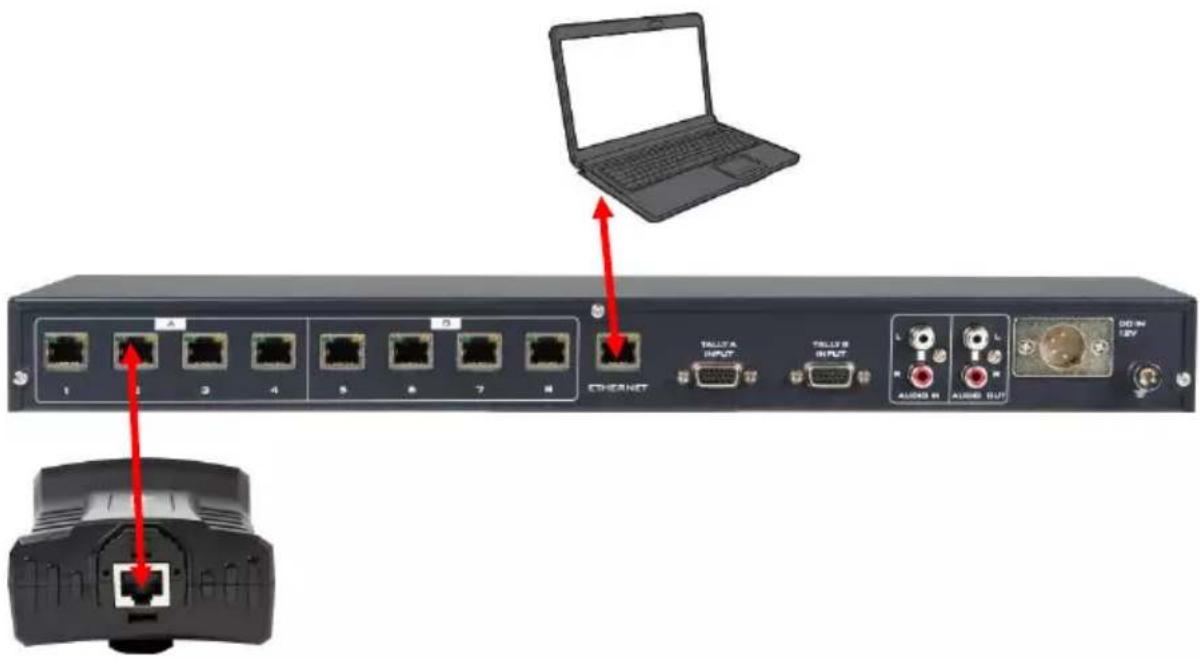
- PC or Laptop
- Ethernet connections with access to the Internet (For firmware downloads)
- Latest firmware files
FlashUpdate_MB_Vxx (ITC-300)
FlashUpdate_SL_Vxx (ITC-300SL)
System Connections
Upgrade Procedure
- Run FlashUpdate_SL_Vxx to update the ITC-300SL firmware and FlashUpdate_MB_Vxx to update the ITC-300 firmware.
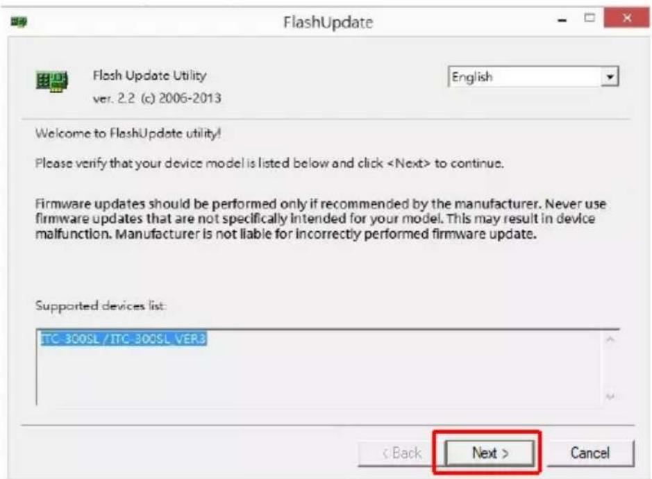
- Turn the ITC-300 base unit off and on the PC, select "Device is connected via Ethernet."
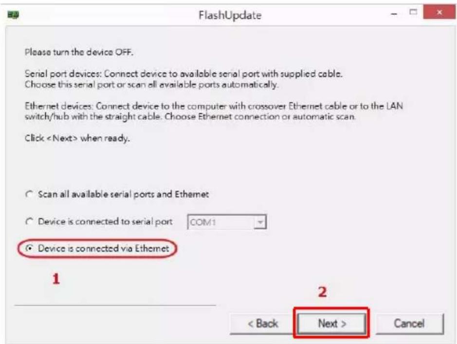
-
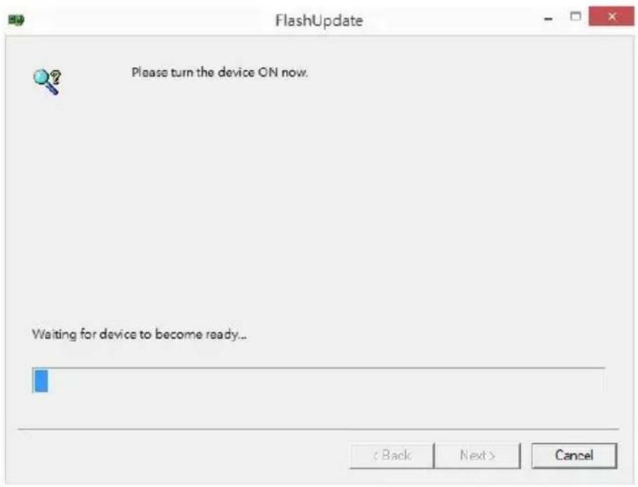
Turn the ITC-300 base unit back on again.
-
If you are upgrading the ITC-300SL, press the CALL button before turning on the ITC-300.
- If you are upgrading the ITC-300, press the SHIFT button before turning on the ITC-300.
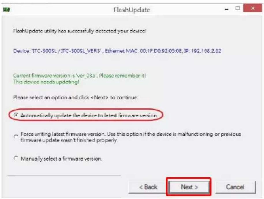
- Select "Automatically update the device to latest firmware version" then click NEXT.
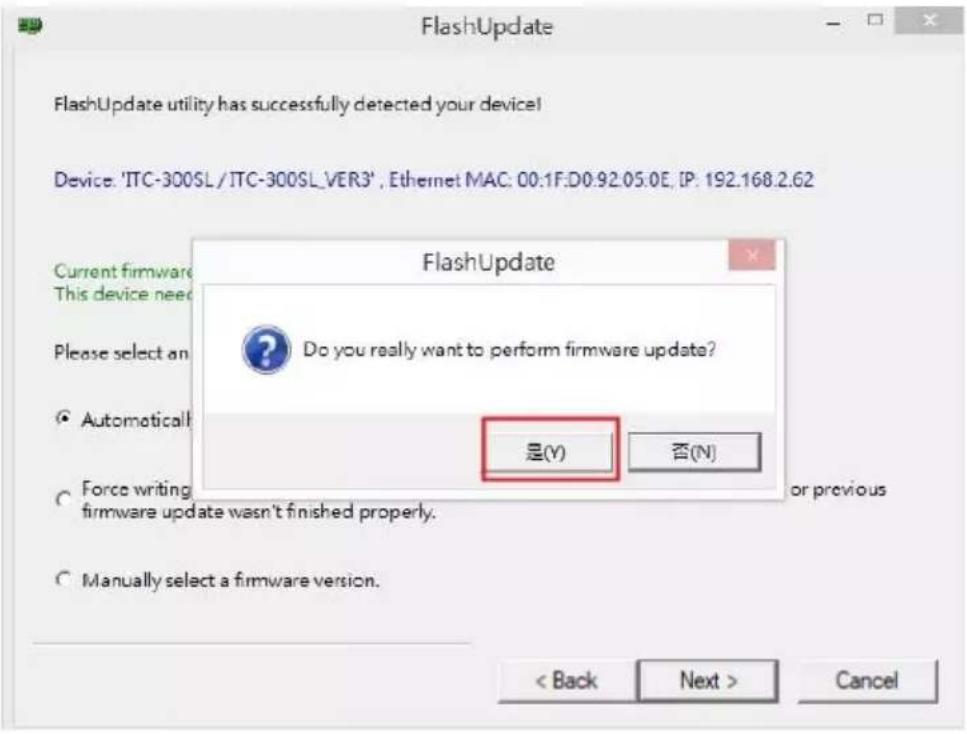
- Click Yes to start the firmware upgrade.
- If you see the screen below, it means the firmware upgrade is in progress.
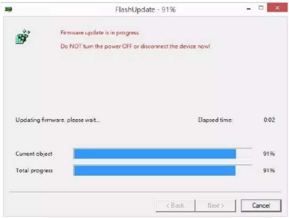
bar
FlashUpdate - 91% | Status | Percentage (%) | | :--- | :--- | | Current object | 91 | | Total progress | 91 |- After the firmware is successfully upgraded, click Finish and shut down the ITC-300 base unit.

FlashUpdate


Firmware update completed.
Please turn the device OFF now.
It will be functional then you turn it back ON next time
Click

Frequently-Asked Questions
This section describes problems that you may encounter while using ITC-300. If you have any questions, please refer to related sections and follow all suggested solutions. If problem still exists, please contact your distributor or the service center.
| No. | Problems | Solutions |
| 1 | Important reminder for connecting the ITC-300 and the ITC-300SL. | Please pay attention that the ITC-300SL must be connected directly to the ITC-300 without router (though it is IP based). The reason is that the power of the ITC-300SL is supplied by the ITC-300. |
Dimensions
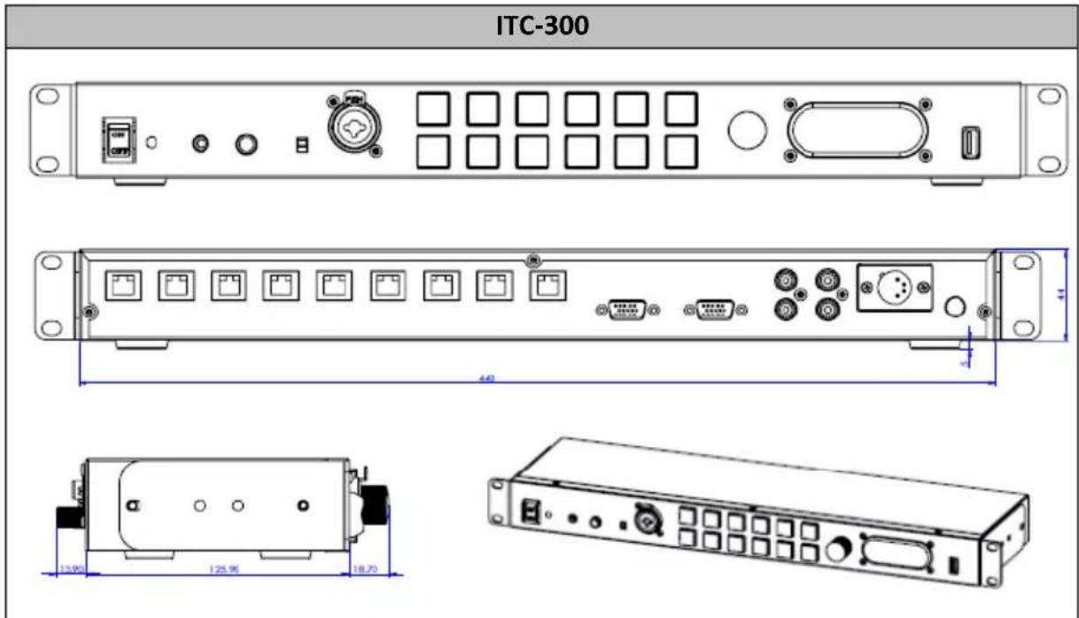
All measurements in millimeters (mm)
Specifications
| Base Station (ITC-300) | |
| Front | |
| Power On/Off Switch | Yes |
| MIC / Headset | 3.5mm Stereo Jack Socket x 1(For Headphone / Microphone combination)Headset Impedance 24 ohms 100mW (min)Input Microphone Level -45.2 dBPin definitionTip: Mic / Ring: Phone / Sleeve: GND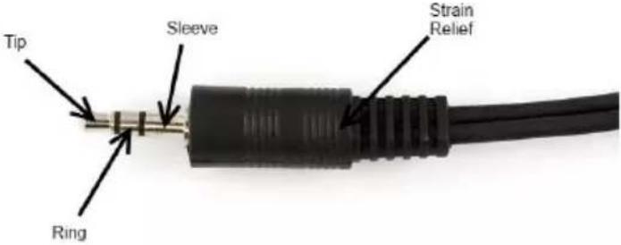 |
| Headphone | 14'' (6.3mm) Stereo Headphone Socket x 1Pin definitionTip: Phone / Ring: Phone / Sleeve: GND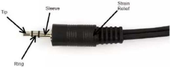 |
| Microphone | 3 Pin XLR / 1/4" (6.3mm) Socket x 1PIN1: N/APIN2: MIC (5V output to the MIC)PIN3: GNDSwitchable Condenser / DynamicInput Microphone Level -67dB |
| Communication | 12 Buttons (Hold / All / Mute / Shift / Key 1-8)Rubber Key (White: backlight, Red: Active, Green: Standby) |
| Volume Control | Controls the Volume of the built-in speaker or outputs to the headphones or mic/headset according to what is connected |
| USB Light Socket | Act as the power source for connected light +5 V output current up to 500mA. |
| Built-in Speaker | 3W Speaker is disabled when headphones or mic / headset are plugged into the ITC-300 |
| Rear | |
| RJ45 Port | RJ45 x 8 (ITC-300) |
| Tally In | 2 x 15 Pin D-Sub Female Sockets for Tally A and Tally B |
| Audio Input/ Output | Audio In / Audio Out (RCA Jack) |
| FW Upgrade | Ethernet |
| Power | 12V Power Input4P Male XLR x 1 (PIN1: GND; PIN4: 12V) |
| Performance | |
| FREQUENCY RESPONSE | 300 Hz ~ 7 KHz, < +/-3dB |
| THD | < 0.1% @1KHz |
| S/N | >70dB |
| OPERATING RANGE | Up to 100m between Base Station and Belt Pack |
| OPERATING TEMPERATURE | 0°C - 40°C [32°F - 104°F] |
| STORAGE TEMPERATURE | -20°C to 60°C (-4°F to 140°F) |
| HUMIDITY | 10% to 80% (non-condensing) |
| DIMENSIONS (mm) | 440 x 126 x 44 |
| WEIGHT | 1.93 Kg |
| Wired Belt Pack (ITC-300SL) | |
| Communication | Call Button x 1Talk Button x 1 |
| MIC / Headset | 3.5mm Stereo Jack Socket x 1(For Headphone / Microphone combination)Headset Impedance 24 ohms 100mW(min)Microphone Level -45.2 dBPin definitionTip: Mic / Ring: Phone / Sleeve: GND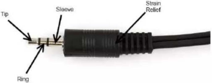 |
| Tally Out Socket | 3.5mm Jack Socket to connect TD-3 Tally Indicator Pin definition Tip: Tally Red (+3.3V) / Ring: Tally Green (+3.3V) / Sleeve: GND |
| Power Switch / Volume Control | VR with Multifunction Switch (Power ON/OFF the belt pack, adjusts the headphone volume) |
| Tally LED | Bi-Color LED – RED indicates LIVE / GREEN Indicates CUED |
| Power LED | Red light |
| Link LED | Yellow light |
| Call LED | Red light – Outgoing call Green light – Incoming call |
| Power | Powered by the Base Unit |
| Performance | |
| FREQUENCY RESPONSE | 300 Hz ~ 7 KHz, < +/-3dB |
| THD | < 0.1% @1KHz |
| S/N | >70dB |
| OPERATING RANGE | Up to 100m between Base Station and Belt Pack |
| OPERATING TEMPERATURE | 0°C - 40°C [32°F - 104°F] |
| STORAGE TEMPERATURE | -20°C to 60°C (-4°F to 140°F) |
| HUMIDITY | 10% to 80% (non-condensing) |
| DIMENSIONS (mm) | 81.2 x 142.6 x 49.6 |
| WEIGHT | 230 g |
Note
Note
Service & Support
It is our goal to make your products ownership a satisfying experience. Our supporting staff is available to assist you in setting up and operating your system. Please refer to our web site www.datavideo.com for answers to common questions, support requests or contact your local office below.

Please visit our website for latest manual update. www.datavideo.com/product/ITC-300
datavideo
www.datavideo.com

@DatavideoUSA
@DatavideoEMEA
@DatavideoTaiwan
@DatavideoAsia
@DatavideoIndia2016
@Datavideojapan
@DatavideoLatam
@DatavideoBrasil

@Datavideo
@Datavideo EMEA
@Datavideo Taiwan

@DatavideoUSA
@DVTWDVCN

@DatavideoUSA
@DatavideoEurope
All the trademarks are the properties of their respective owners.
Datavideo Technologies Co., Ltd. All rights reserved 2020

- Table of Contents
- TABLE OF CONTENTS 2
- FCC COMPLIANCE STATEMENT 4
- WARNINGS AND PRECAUTIONS 4
- WARRANTY 5
- DISPOSAL 6
- PRODUCT OVERVIEW 8
- SYSTEM OVERVIEW....11
- FUNCTION KEYS....21
- Disclaimer of Product & Services
- FCC Compliance Statement
- Warnings and Precautions
- Warranty
- Standard Warranty
- Three Year Warranty
- Disposal
- For EU Customers only - WEEE Marking
- CE
- Product Overview
- Features
- Front Panel
- Rear Panel
- ITC-300SL Belt Pack
- System Diagram
- The ITC-300 Interfacing the SE-3200 HD Video Switcher via Tally Inputs
- The VP-300R Intercom Repeater Interfacing between the ITC-300 and the ITC-300SL
- System Overview
- Base Unit
- On/Off Switch
- XLR Microphone Socket
- Headphone Socket
- Microphone / Headset Socket
- ALL Button
- HOLD Button
- Channel Buttons 1 - 8
- Mute Button
- SHIFT Button
- Volume Control
- Built-In Speaker
- USB Light Socket
- Belt Pack Channel Ports
- Ethernet Port
- Tally Inputs A / B
- Audio IN/OUT
- DC Power IN
- Ground Terminal
- Belt Pack
- RJ-1M Protective Shield
- Control Panel
- Power Switch / Audio Control knob
- Link LED Indicator
- MIC / Headphone Socket
- Call Button
- Talk Button
- External Tally LED Socket
- Bi-Color Tally LED
- Device Pairing Procedure
- Check the Belt Pack's Paired Channel with the Base Unit
- Clearing Channel Assignment
- Noise Reduction
- Function Keys
- Check the Belt Pack's Channel Assignment
- Group Communication
- All Communication
- Cross Communication (Party Mode)
- How to Operate the Base Unit to Communicate with up to 4 belt packs Simultaneously under Party Mode
- Audio IN
- Panel's Backlight Brightness
- Mute Mode
- Factory Reset
- Tally Input
- Tally A Input Pin Definition
- Tally B Input Pin Definition
- Tally Cables for Connecting Datavideo Switchers and ITC-300
- Firmware Update
- Firmware Upgrade Requirements
- Upgrade Procedure
- FlashUpdate
- Frequently-Asked Questions
- Dimensions
- Specifications
- Note
- Service & Support
- datavideo
Brand : DataVideo
Model : ITC-300
Category : Intercom