
AP-7V - Appareil électronique de contrôle Electronics International - Free user manual and instructions
Find the device manual for free AP-7V Electronics International in PDF.


| Product Type | Aircraft Annunciator Panel |
| Brand | Electronics International |
| Model | AP-7V (Vertical) |
| Dimensions (Panel) | 4.85 in x 5.00 in (123 mm x 127 mm) |
| Weight | Approx. 0.5 lb (0.23 kg) |
| Power Supply | Aircraft electrical system (12V or 24V DC) |
| Voltage Range | 12-24V DC (nominal) |
| Power Consumption | Less than 0.5A (typical) |
| Warning Light Functions | EGT/CHT, Fuel, RPM, M.P., Oil, Volts, Start |
| Dimmer Control | Front panel switch (dim/off) |
| External Warning Inputs | Compatible with E.I. instruments (US-8A, FP-5, R-1, M-1, OPT-1) |
| Installation Type | Panel mount, minor alteration (per AC 43.13-2A) |
| Certification | Not STC'd; installation qualifies as minor alteration |
| Warranty | 1 year from user invoice date (parts and labor) |
| Operating Temperature | Aircraft cabin environment (-20°C to +55°C typical) |
| Primary Material | Aluminum front panel, plastic control box |
| Safety | Must be installed by FAA certified mechanic; read entire manual before installation |
| Maintenance | Self-test on power-up; periodic check of warning lights |
| Spare Parts Availability | Contact manufacturer for replacement units |
Frequently Asked Questions - AP-7V Electronics International
User questions about AP-7V Electronics International
0 question about this device. Answer the ones you know or ask your own.
Ask a new question about this device
Download the instructions for your Appareil électronique de contrôle in PDF format for free! Find your manual AP-7V - Electronics International and take your electronic device back in hand. On this page are published all the documents necessary for the use of your device. AP-7V by Electronics International.
USER MANUAL AP-7V Electronics International
(AP-7H and AP-7V)(AP-7H and AP-7V)
Operating and Installation Instructions Operating
OI 0908931
9/8/93
You must read this manual before installing or operating the instrument. This manual contains warranty and other information that may affect your decision to install this product and/or the safety of your aircraft.

S/N:S/N:

Electronics International Inc. Electro
63296 Powell Butte Hwy • Bend, OR 97701 • (541) 318-6060 • Buy-El.com

Important Notice Important Notice
\*\*\*\*\* MUST READ \*\*\*\*\* MUST RE
If you think it is not important to read this manual, you're wrong! This manual This manual contains important installation information that may affect the safety of your aircraft, delay your installation or affect the operation of your instrument. You MustMust read this manual prior to installing your instrument.read this manual prior to installing your inst
Read the Warranty / Agreement Read this Waformation Agreement Warranty / Agreement that may alter your decision to install this product. If you do not accept the terms of the Warranty / Agreement, do not install this product install this product be returned for a refund. Contact Electronics International inc. for details.
Check that the instrument make and model marked on the side of the instrument and on the invoice are correct before starting the installation.
It is possible for any instrument to fail thereby displaying inaccurate operation. Therefore, you must be able to recognize an instrument failure and you must be proficient in operating your aircraft safely in spite of an instrument failure. If you do not have this knowledge, contact the FAA or a local flight instructor for training.
The pilot must understand the operation of this product before flying the aircraft. Do not allow anyone to operate the aircraft that does not know the operation of this product. Keep the Operating Manual in the Keep the Operating aircraft at all times. aircraft at all times.
ContentsContents
Warranty 2
Operating Instructions 3
Installation Instructions 4
ImportantNotice 4
VerifytheTemplateSize 4
MarktheHoles 4
DrilltheHoles 4
Mount the AP-7 Front Panel 4
Mount the AP-7 Control Box 5
Connect the Power Supply and Control Lines 5
Troubleshooting 6
STC Information 6
Wiring Diagram 7
Template 8
Warranty / Agreement
Electronics International Inc. warrants this instrument and system components to be free from defects in materials and workmanship for a period of one year from the user invoice date. Electronics International Inc. will repair or replace any item under the terms of this Warranty provided the item is returned to the factory prepaid.
- This Warranty shall not apply to any product that has been repaired or altered by any person other than Electronics International Inc., or that has been subjected to misuse, accident, incorrect wiring, negligence, improper or unprofessional assembly or improper installation by any person. This warrantyThis warran does not cover any reimbursement for any person's time for installation, removal, assembly or repair. Electronics International retains the right to determine the reason or cause for warranty repair.
- This warranty does not extend to any machine, vehicle, boat, aircraft or any other device to which the Electronics International Inc. product may be connected, attached, interconnected or used in conjunction with in any way.
- The obligation assumed by Electronics International Inc. under this warranty is limited to repair, replacement or refund of the product, at the sole discretion of Electronics International Inc.
- Electronics International Inc. is not liable for expenses incurred by the customer or installer due to factory updates, modifications, improvements, upgrades, changes, or any other alterations to the product that may affect the form, fit, function or operation of the product.
- Personal injury or property damage do to misinterpretation or lack of understanding this product is solely the pilots responsibility. The pilot must understand the operation of this product before flying the aircraft. Do not allow anyone to operate the aircraft that does not know the operation of this product. Keep the Operating Manual in the aircraft at all times.
- E. I. Inc. is not responsible for shipping charges or damages incurred under this Warranty.
- No representative is authorized to assume any other liability for Electronics International Inc. in connection with the sale of Electronics International Inc. products.
- If you do not agree to and accept the terms of this warranty, you may return the product for a refund.refund.
This Warranty is made only to the original user. THIS WARRANTY IS IN LIEU OF ALL OTHERTHIS WARRANTY WARRANTIES OR OBLIGATIONS: EXPRESS OR IMPLIED. MANUFACTURER EXPRESSLY DISCLAIMS ALL IMPLIED WARRANTIES OF MERCHANTABILITY OR FITNESS FOR A PARTICULAR PURPOSE. PURCHASER AGREES THAT IN NO EVENT SHALL MANUFACTURER BE LIABLE FOR SPECIAL, INCIDENTAL OR CONSEQUENTIAL DAMAGES, INCLUDING LOST PROFITS OR LOSS OF USE OR OTHER ECONOMIC LOSS. EXCEPT AS EXPRESSLY PROVIDED HEREIN, MANUFACTURER DISCLAIMS ALL OTHER LIABILITY TO PURCHASER OR ANY OTHER PERSON IN CONNECTION WITH THE USE OR PERFORMANCE OF MANUFACTURER'S PRODUCTS, INCLUDING SPECIFICALLY LIABILITY IN TORT.TORT.
Operating Instructions Operating Instruction
AP-7H and AP-7VAP-7H and AP-7V
The Annunciator Panel (AP-7) provides a quick and convenient way of spotting a problems or warnings without having to scan your instrument panel and interpret each gauge. If the AP-7 is mounted high on the instrument panel, you can spot the many available warnings while still keeping your focus outside the cabin.
Five of the AP-7 warning lights are controlled by External Warning Lines available on the following E.I. instruments:
| AP-7Warning Light | Controlling Instrument | Warnings Provided on the AP-7 |
| EGT/CHT US-8A, SR | R-8A,EC-1P, E-1P, C-1P,etc.(Warnings shown using US-8A) | EGT Over Temp (all Cylinders)EGT Under Temp (all Cylinders)EGT Differential TempCHT Over Temp (all Cylinders)CHT Under Temp (all Cylinders)CHT Differential TempCHT Shock-Cooling (Blinks Light)Other temp Warnings |
| Fuel FP-5 and/or | FL-2. | Low Fuel Warnings (Two Warnings)Time to Empty WarningHigh Fuel Pressure WarningLow Fuel Pressure Warning |
| RPM R-1 High RPM | Warning | |
| M.P. M-1 High Manifold | Pressure | |
| Oil OPT-1 High Oil | Pressure | Low Oil PressureHigh Oil Temp |
| Volts None Low Voltage | Discharging Cond | tion) |
| Start None Starter Engaged | ||
The “Volts” and “Start” Warning Lights are controlled by the AP-7 Control Box.
Refer to the appropriate operating manual for the operation of the EGT/CHT, Fuel, RPM, M.P. and Oil Warning Lights.
The “Start” Warning Light will come on when the starter is engaged. After the engine is started this light should be out. If it does not go out, the starter or starter solenoid may be stuck on. Flying the aircraft in this condition can cause starter and/or engine failure.
The “Volts” Warning Light will be on when the master switch is on and the engine is off. This indicates the battery is in a discharging condition. When the engine is started this light will go out. If the alternator (or generator) cannot supply the aircraft’s electrical load, this light will come on. During a takeoff, climb or cruise condition the “Volt” Warning Light should be out. During operation with low engine power with a high electrical load (e.g., the engine is at idle during night operation with all the lights on), this light may come on. A point to remember: if the “Volts” Warning Light is on, your battery is discharging.
The switch on the AP-7 allows the pilot to dim or turn off the Warning Lights. All the Warning Lights (except the “Start” light) will flash on power-up. This allows the pilot to check the lights as well as the controlling instruments, circuits and interconnects for proper operation. The “Start” Warning Light can be checked when the starter is engaged.
Installation Instructions Installation Instruct
AP-7H and AP-7VAP-7H and AP-7V
Important Notice:
- The installer and aircraft owner must read the Warranty before starting the installation. There is information in the Warranty that may alter your decision to install this instrument. If you do not acceptIf you do not a the terms of the Warranty, do not install this instrument.the terms of the Warranty, do not install this instrument.
- If you are not an FAA Certified Aircraft Mechanic familiar with the issues of installing aircraft annunciator panels, DiatNopantempt to install this panel.DThe installed should include this panel aircraft standards The installer and practices to install this instrument (refer to AC 43.13).
- This panel's installation could be considered a minor alteration (as is true for clocks, radios, intercoms, headsets, etc.). Installation can be accomplished utilizing FAA acceptable methods, techniques and practices covered under AC 43.13-2A. This is a requirement under FAR Part 1 to qualify as a minor alteration. This panel does not "appreciably" effect weight and balance or electrical load as described in FAR Part 1 and FAR 43 Appendix A. Also, this panel meet the environmental requirements of DO-160B. The panels are manufactured in Electronics International's FAA PMA/TSO approved manufacturing facility. If the installer determines that this installation is minor, he must say so in the log book. Example: "3/21/96 Installed Electronics International's AP-7H as a minor alteration. This panel was installed in accordance with Installation Instructions OI 0908931 dated 9/8/93 and AC 43.13-2A." A minor alteration does not require a 337. Resolve any FAA approval issues you may have before start-Resolve any F ing the installation, ing the installation.
- For any lights that are not operational the nomenclature must be covered.
- Read the entire Installation Instructions and resolve any issues you may have before starting the installation. This may eliminate any delays once the installation is started.
-
THIS INSTALLATION MAY REQUIRE SOME PARTS UNIQUE TO YOUR AIRCRAFT THAT ARE NOT SUPPLIED IN THE KIT. Acquire all the parts necessary to install this instrument before starting the installation.
-
Before starting the installation make sure the unit will fit in the location you intend to install it without obstructing the operation of any controls.
Verify the Template Size:
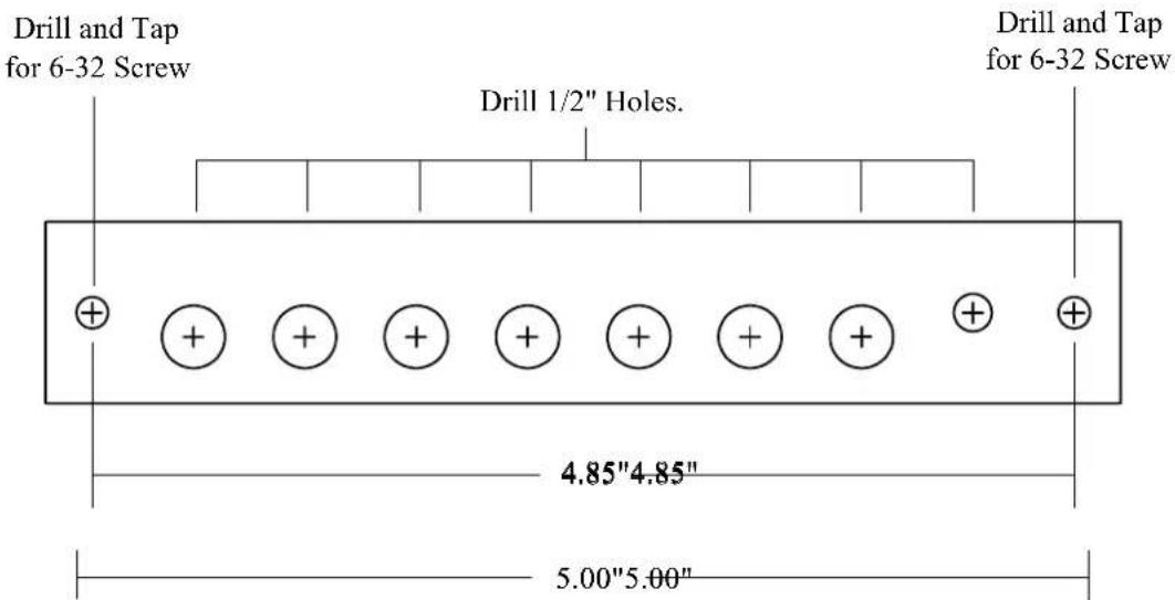
Check the AP-7 Template at the back of this manual. Copy machines can alter the size of a drawing. If the template is not accurate, use a variable sizing copy machine and make an accurate copy of the template.
Mark the Holes:
Use the AP-7 Template provided at the back of this manual to center punch the AP-7 Front Panel Holes on your aircraft's instrument panel. Make sure you will not be drilling through any structural supports or compromising the structural integrity of the aircraft's instrument panel.
Drill the Holes:
Drill each of the Switch and Warning Light holes using a 1/2" drill. The outside mounting holes should be drilled and tapped for a 6-32 screw. Two black 6-32 screws are provided in the kit.
Mount the AP-7 Front Panel:
Route each of the Warning Light leads through the appropriate hole and mount the AP-7 Front Panel on the aircraft's instrument panel. A small amount of loctite may be used on the 6-32 mounting screws.
Mount the AP-7 Control Box:
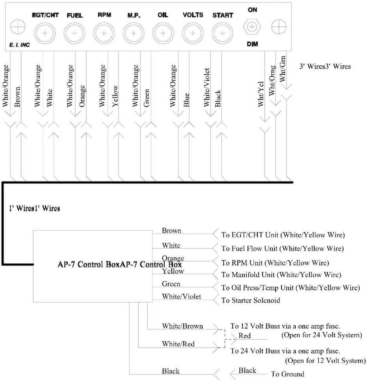
Connect the AP-7 Front Panel wires to the AP-7 Control Box (see AP-7 Wiring Diagram). Tie wrap all the Tie wrap all wires so they do not obstruct the freedom of travel of any controls. Leave some slack in the wires near the AP-7 Front Panel so it can be pulled back away from the aircraft's instrument panel in the event it ever needs to be worked on. The AP-7 Control Box may be mounted to a wire bundle under the instrument panel using two tie wraps (one on each side of the Control Box).
Connect the Power Supply and Control Lines:
Connect the External Warning Control Lines (White/Yellow wires) from the appropriate E.I. Instruments to the AP-7 Control Box (see AP-7 Wiring Diagram and the appropriate installation manual). Male slip-on connectors are provided in the kit. Double the wires over and double crimp these connectors.

Connect the White/Violet Wire from the AP-7 Control Box to the starter solenoid. A male slip-on connector is provided in the kit.
Connect the loose red wire in the kit to the bus via a one amp fuse (see AP-7 Wiring Diagram).
Connect the loose black wire in the kit to ground.
Troubleshooting:
The Warning Lights on the AP-7 Front Panel can be tested by shorting the appropriate wire on the AP-7 Control Box. To light a Warning Light perform the following:
| AP-7Warning Light | AP-7 Control Box Wire |
| EGT/CHT Short the Brown Wire to Ground. | |
| Fuel Short the White Wire to Ground. | |
| RPM Short the Orange Wire to Ground. | |
| M.P. Short the Yellow Wire to Ground. | |
| Oil Short the Green Wire to Ground. | |
| Start Short the White/Violet Wire to the Bus. | |
The "Volts" Warning Light comes on when the bus voltage drops below 12.5 volts on a 12 volt system or 25 volts on a 24 volt system. If you have trouble with this light, check the white/brown and white/red wires on the Control Box for proper connection (see AP-7 Wiring Diagram).
STC InformationSTC Information
The AP-7 Annunciator Panels are not STC'd. The Alpha Annunciator Requils are hot to be Approval. Contact your local mechanic and/or GATO. The installation manuals for each of the FAA approved controlling instruments describe connecting the external warning lines to a warning device.
AP-7AP-7
Wiring Diagram Wiring Diagram
AP-7 Front PanelAP-7 Front Panel
flowchart
graph TD
    A["1' Wires1' Wires"] --> B["AP=7 Control Box"]
    B --> C["Black"]
    B --> D["White/Red"]
    B --> E["White/Brown"]
    B --> F["White/Violet"]
    B --> G["Green"]
    B --> H["Yellow"]
    B --> I["Orange"]
    B --> J["White/Orange"]
    B --> K["White/Orange"]
    B --> L["Blue"]
    B --> M["White/Organ"]
    B --> N["Green"]
    B --> O["White/Organ"]
    B --> P["Yellow"]
    B --> Q["White/Orange"]
    B --> R["White/Orange"]
    B --> S["White/Orange"]
    B --> T["White/Organ"]
    B --> U["Blue"]
    B --> V["White/Violet"]
    B --> W["Black"]
    B --> X["White/Organ"]
    B --> Y["Green"]
    B --> Z["White/Organ"]
    B --> AA["White/Orange"]
    B --> AB["White/Orange"]
    B --> AC["FUEL"]
    B --> AD["RPM"]
    B --> AE["M.P."]
    B --> AF["OIL"]
    B --> AG["VOLTS"]
    B --> AH["START"]
    B --> AI["ON"]
    A --> AJ["E.I.INC"]
    AJ --> AK["+"]
    AK --> AL["+"]
    AL --> AM["+"]
    AM --> AN["+"]
    AN --> AO["+"]
    AO --> AP["+"]
    AP --> AQ["+"]
    AQ --> AR["+"]
    AR --> AS["+"]
    AS --> AT["+"]
    AT --> AU["+"]
    AU --> AV["+"]
    AV --> AW["+"]
    AW --> AX["+"]
    AX --> AY["+"]
    AY --> AZ["+"]
    AZ --> BA["+"]
    BA --> BB["+"]
    BB --> BC["+"]
    BC --> BD["+"]
    BD --> BE["+"]
    BE --> BF["+"]
    BF --> BG["+"]
    BG --> BH["+"]
    BH --> BI["+"]
    BI --> BJ["+"]
    BJ --> BK["+"]
    BK --> BL["+"]
    BL --> BM["+"]
    BM --> BN["+"]
    BN --> BO["+"]
    BO --> BP["+"]
    BP --> BQ["+"]
    BQ --> BR["+"]
AP-7AP-7
TemplateTemplate
Check the template below for accuracy. Copy machines can alter the size of a drawing. If the template is not accurate, use a variable sizing copy machine and make an accurate copy of the template.
- (AP-7H and AP-7V)(AP-7H and AP-7V)
- Operating and Installation Instructions Operating
- Important Notice Important Notice
- \*\*\*\*\* MUST READ \*\*\*\*\* MUST RE
- ContentsContents
- Warranty 2
- Operating Instructions 3
- Installation Instructions 4
- STC Information 6
- Wiring Diagram 7
- Template 8
- Warranty / Agreement
- Operating Instructions Operating Instruction
- Installation Instructions Installation Instruct
- Important Notice:
- Verify the Template Size:
- Mark the Holes:
- Drill the Holes:
- Mount the AP-7 Front Panel:
- Mount the AP-7 Control Box:
- Connect the Power Supply and Control Lines:
- Troubleshooting:
- STC InformationSTC Information
- AP-7AP-7
- Wiring Diagram Wiring Diagram
- TemplateTemplate
Brand : Electronics International
Model : AP-7V
Category : Appareil électronique de contrôle