
HMIPW-FAL230-C6 - Home Automation Homematic IP - Free user manual and instructions
Find the device manual for free HMIPW-FAL230-C6 Homematic IP in PDF.


| Product Type | Wired Floor Heating Actuator |
| Model | HMIPW-FAL230-C6 |
| Number of Heating Zones | 6 |
| Number of Actuators (max) | 9 (or 8 with pump control) |
| Pump Control | Yes, via channel 1 (H terminal) |
| Supply Voltage (control) | 24 V DC, +5%, SELV |
| Switching Voltage | 230 V ~ |
| Current Carrying Capacity per Channel | Σ 6 A |
| Switching Capacity per Heating Zone (drive) | 1 A max. |
| Dimensions (W x H x D) | 225 x 75 x 52 mm |
| Weight | 380 g |
| Mounting Options | Screw mounting (wall) or DIN rail (EN50022) |
| Communication Protocol | Homematic IP Wired Bus |
| Operation Modes | Heating and Cooling (if system supports) |
| Valve Protection Function | Adjustable duration (0–10 min) and interval (1–28 days) |
| Protection Rating | IP20 |
| Ambient Temperature | 0 to 40 °C |
| Maintenance | None required; clean with soft, dry cloth |
| Installation Requirements | Qualified electrician (VDE 0100); disconnect mains before work |
| System Compatibility | Homematic IP CCU3, Wired Access Point, cloud via app |
Frequently Asked Questions - HMIPW-FAL230-C6 Homematic IP
User questions about HMIPW-FAL230-C6 Homematic IP
0 question about this device. Answer the ones you know or ask your own.
Ask a new question about this device
Download the instructions for your Home Automation in PDF format for free! Find your manual HMIPW-FAL230-C6 - Homematic IP and take your electronic device back in hand. On this page are published all the documents necessary for the use of your device. HMIPW-FAL230-C6 by Homematic IP.
USER MANUAL HMIPW-FAL230-C6 Homematic IP
Installation instruction and operating manual
Wired Floor Heating Actuator – p. 47 6 channels, 230 V

Lieferumfang
Anzahl Bezeichnung
Printed in Hong Kong
2
3

4

natural_image
Technical line drawing of a mechanical assembly with mounting holes and internal components (no text or symbols)5

natural_image
Line drawing of a mechanical component with a screwdriver inserted, no text or symbols present6

natural_image
Technical line drawing of an electronic device interior with a screwdriver inserted, showing internal components and wiring layout (no text or symbols)7
Selecttaste drücken
press select button

natural_image
Line drawing of a hand opening a rectangular electronic device (no text or symbols)Systemtaste drücken
press system button

natural_image
Line drawing of a hand gripping a rectangular box (no text or symbols)Inhaltsverzeichnis
6.3 Installation....19
1 Homematic IP Wired Floor Heating
Actuator - 6 channels, 230 V
2 Screws 4.0 x 40 mm
2 Plugs 6 mm
1 User manual
Documentation © 2018 eQ-3 AG, Germany.
All rights reserved. Translation from the original version in German. This manual may not be reproduced in any format, either in whole or in part, nor may it be duplicated or edited by electronic, mechanical or chemical means, without the written consent of the publisher.
Typographical and printing errors cannot be excluded. However, the information contained in this manual is reviewed on a regular basis and any necessary corrections will be implemented in the next edition. We accept no liability for technical or typographical errors or the consequences thereof.
All trademarks and industrial property rights are acknowledged.
Printed in Hong Kong
Changes may be made without prior notice as a result of technical advances.
152708 (web)
Version 1.0 (12/2018)
Table of contents
1 Information about this manual.... 50
2 Hazard information....50
3 Function and device overview ....54
4 General system information ....55
5 Mounting....55
5.1 Screw mounting.... 56
5.2 DIN rail mount....56
6 Start-up 57
6.1 Installation instructions 57
6.2 Cable diameter and cable cross-sections....59
6.3 Installation....60
6.4 Behaviour after switching on the power supply ...... 62
6.5 Behaviour after switching on the power supply ...... 62
6.6 Teaching-in 63
6.6.1 Pairing with a Homematic IP Wired Wall Thermostat....64
6.6.2 Adding a new floor heating actuator....65
6.6.3 Connecting to the CCU3 66
6.6.4 Connecting to the Homematic IP cloud via Wired Access Point....69
7 Configuration via the Wired Wall Thermostat.....70
8 Manual operation....78
8.1 Switch heating zones on/off 78
8.2 Activating/deactivating the pump control 78
9 Delete device connections....79
10 Error codes and flashing sequences....80
10.1 Flashing sequences of the system LED (A).....80
10.2 Flashing sequences of the channel LED (B)....81
11 Restore factory settings....81
12 Maintenance and cleaning....82
13 Technical specifications....82
1 Information about this manual
Please read this manual carefully before beginning operation with your Homematic IP Wired component. Keep the manual so you can refer to it at a later date if you need to.
If you hand over the device to other persons for use, please hand over this manual as well.
Symbols used:

Attention!
This indicates a hazard.

Please note: This section contains important additional information.
2 Hazard information

Do not open the device. It does not contain any parts that can be maintained by the user. If you have any doubts, have the device checked by an expert.

For safety and licensing reasons (CE), unauthorized change and/or modification of the device is not permitted.

Do not use the device if there are signs of damage to the housing, control elements or connecting sockets, for example. If you have any doubts, have the device checked by an expert.

The device may only be operated in dry and dust-free environment and must be protected from the effects of moisture, vibrations, solar or other methods of heat radiation, cold and mechanical loads.

The device is not a toy; do not allow children to play with it. Do not leave packaging material lying around. Plastic films/bags, pieces of polystyrene, etc. can be dangerous in the hands of a child.

We do not assume any liability for damage to property or personal injury caused by improper use or the failure to observe the hazard information. In such cases, any claim under warranty is extinguished! For consequential damages, we assume no liability!

The actuator is part of the building installation. The relevant national standards and directives must be taken into consideration during planning and set-up. The device has been designed solely for operation on a 230 V supply. Only qualified
electricians (to VDE 0100) are permitted to carry out work on the 230 V mains. Applicable accident prevention regulations must be complied with whilst such work is being carried out. To avoid electric shocks from the device, please disconnect the mains voltage (trip the miniature circuit-breaker). Noncompliance with the installation instructions can cause fire or introduce other hazards.

SELV/PELV power circuits may not be connected to the switching outputs.

The device may only be used for fixed installations. The device must be securely attached within a fixed installation.

When connecting to the device terminals, take the permissible cables and cable cross sections into account.

Please take the technical data (in particular the maximum permissible effective installed load of the floor heating actuator and the type of load to be connected) into account before connecting a load! All load data relates to ohmic loads. Do not exceed the capacity specified for the device.

The supply circuit has to be secured by a cable protection switch in accordance with EN 60898-1 (tripping characteristic B or C, max. 6 A rated current, min. 6 KA interrupting rating, energy limiting class 3).

The device has not been designed to support safety disconnection.

Exceeding this capacity could lead to the destruction of the device, fires or electric shocks.

Before the actuator is connected, remove the fuse from the fuse box.

Observe the installation instructions for installation in distribution systems (DIN VDE 0100-410).

The device may only be operated within domestic environment, in business and trade areas as well as in small enterprises.

Using the device for any purpose other than that described in this operating manual does not fall within the scope of intended use and shall invalidate any warranty or liability.
3 Function and device overview
The Homematic IP Wired Floor Heating Actuator offers comfortable and demand-based room-by-room control of your floor heating system via smartphone app or the Homematic IP Wired Wall Thermostat, according to your personal needs.
The floor heating actuator can be used for controlling a floor heating system with up to 6 heating zones/9 heating circuits as well as a heating pump or circulation pump. Furthermore, the device offers operation in heating or cooling mode (provided that your heating system offers these operating modes).
You can flexibly mount the device using the supplied screws or a DIN rail in the heating circuit distribution board.
Device overview (see fig. 1):
(A) System button (teach-in/pairing button and LED)
(B) Select button (channel button and LED)
(C) Slot for opening
(D) Cover
(E) Spring latch for DIN rail mounting
(F) PE connecting terminals
(G) N (neutral conductor) and L (phase conductor) connecting terminals
(H) Heating valves or heating pump connecting termi-
nals
(I) Heating valves connecting terminals
(J) Bus connection 1 (24 V, GND, A, B)
(K) Bus connection 2 (24 V, GND, A, B)
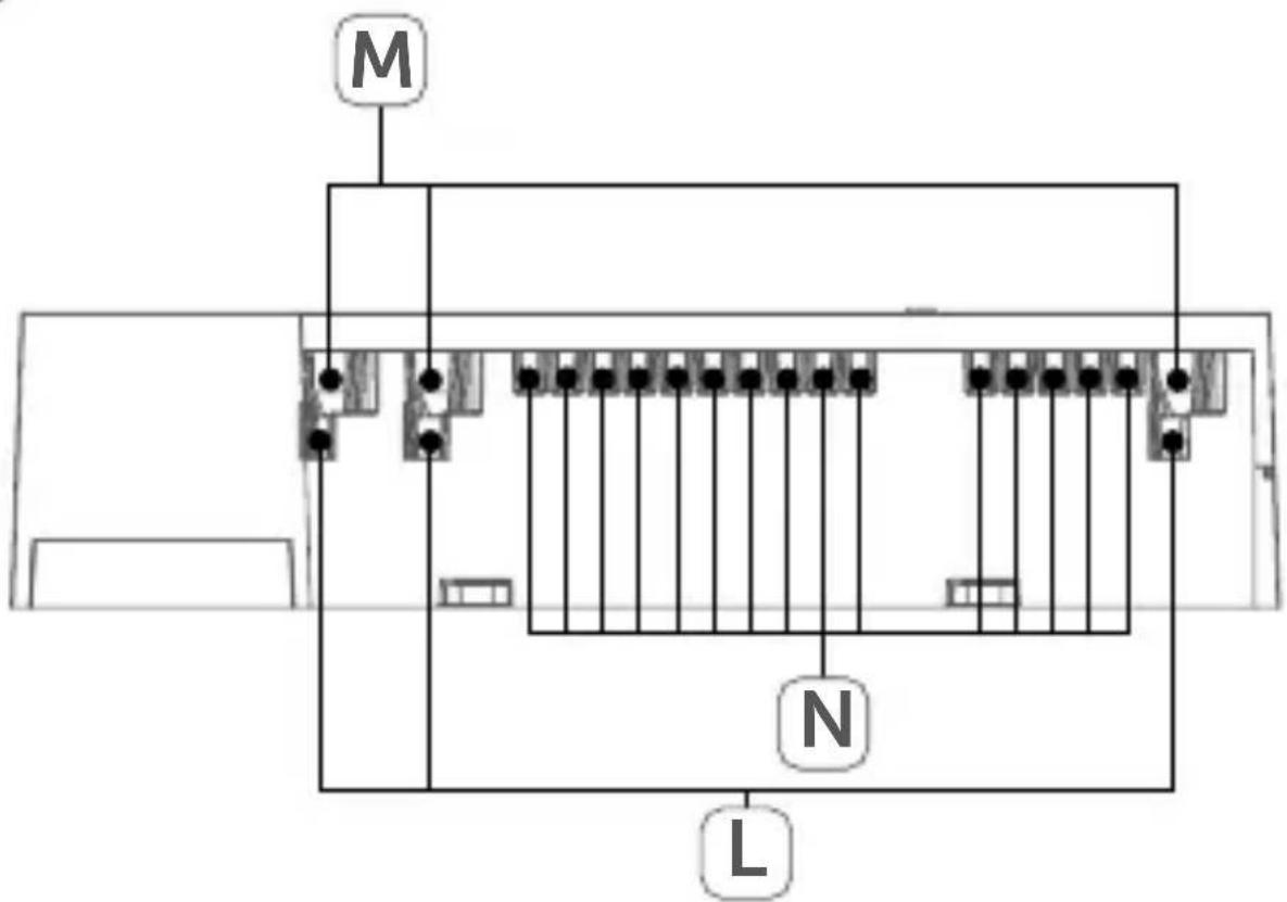
Cable bushings (see fig. 2):
(L) Cable bushing 1
(M) Cable bushing 2
(N) Cable bushing 3
4 General system information
This device is part of the Homematic IP smart home system and works with the Homematic IP protocol. All devices of the system can be configured comfortably and individually with the user interface of the Central Control Unit CCU3 or flexibly via the Homematic IP smartphone app in connection with the Homematic IP cloud. All available functions provided by the system in combination with other components are described in the Homematic IP Wired Installation Guide. All current technical documents and updates are provided at www.eQ-3.com.
5 Mounting
You can flexibly mount the floor heating actuator to a wall using the supplied screws or to a DIN rail.
5.1 Screw mounting
For mounting the floor heating actuator using screws, please proceed as follows:
- Please select a suitable mounting location close to your heating manifold.

Make sure that no electricity or similar lines run in the wall at this location!
- Use a pen to mark the positions of the two bore holes with a distance of 13.6 cm on the wall (see figure 3).
- Use an appropriate drill to make the holes as illustrated.
- Use the supplied screws and plugs to fasten the floor heating actuator (see fig. 3).
5.2 DIN rail mount
For mounting the floor heating actuator to a DIN rail, please proceed as follows:
- Place the floor heating actuator onto the DIN rail (see fig. 4).
- Latch the floor heating actuator by pressing the spring latches (E) upwards (see fig. 4).
- Make sure that the spring latches are completely latched and that the device is seated solidly on the rail.
6 Start-up
6.1 Installation instructions

Before installing and setting up the device, you have to put a Homematic IP Wired Access Point (HmIPW-DRAP) into operation first.

Before installation, please note the device number (SGTIN) labelled on the device as well as the exact application purpose in order to make later allocation easier. You can also find the device number on the QR code sticker supplied.

Please note! Only to be installed by persons with the relevant electro-technical knowledge and experience!*
Incorrect installation can put
- your own life at risk;
- and the lives of other users of the electrical system.
Incorrect installation also means that you are running the risk of serious damage to property, e.g. because of a fire. You may be personally liable in the event of injuries or damage to property.
Contact an electrical installer!
*Specialist knowledge required for installation:
The following specialist knowledge is particularly important during installation:
- The "5 safety rules" to be used: Disconnect from mains; Safeguard from switching on again; Check that system is deenergised; Earth and short circuit; Cover or cordon off neighbouring live parts;
- Select suitable tool, measuring equipment and, if necessary, personal safety equipment;
- Evaluation of measuring results;
- Selection of electrical installation material for safeguarding shut-off conditions;
• IP protection types;
• Installation of electrical installation material; - Type of supply network (TN system, IT system, TT system) and the resulting connecting conditions (classical zero balancing, protective earthing, required additional measures etc.).

For installing the floor heating actuator into a power distribution panel it has to be mounted in accordance with VDE 0603, DIN 43871 (low-voltage sub-distribution board), DIN 18015-x. In this case, the installation must be made on a mounting rail (DIN rail) according to EN50022. Installation and wiring have to be performed according to VDE 0100 (VDE 0100-410, VDE 0100-510 etc.). Please consider the technical connection requirements (TAB) of your energy supplier.

Please note the insulation stripping length of the conductor to be connected, indicated on the device.

Please observe the hazard information in section "2 Hazard information" on page <?> during installation.
6.2 Cable diameter and cable cross-sections
Permitted cable diameter for the cable bushings of the floor heating actuator are:
| Cable bushings Cable diameter [mm] | maximum cable diameter [mm] |
| 1 (L) (see fig. 2) > 5.2 5.8 | |
| 2 (M) (see fig. 2) > 8.2 11.0 | |
| 3 (N) (see fig. 2) > 3.2 5.0 |
Permitted cable cross sections for connecting to the connecting terminals of the floor heating actuator:
| rigid cable [mm2] Flexible | cable without ferrule [mm2] |
| 0.5 – 1.50 0.5 – 1.50 |

For electrical safety reasons, only the supplied Homematic IP Wired Bus Cable may be used for connecting the device to the Homematic IP Wired bus. Furthermore, an eQ-3 Homematic IP Wired Bus Cable with other lengths (available as accessory) can be used.
6.3 Installation
To install the floor heating actuator, please proceed as follows:
- Open the cover (D). Therefore, release the catch under the slot for opening (C) by pushing it with a screwdriver. Remove the cover by pulling it upwards (see fig. 5).
- Connect the neutral conductor to connecting terminal N (H).

Press the terminal down using an appropriate screw driver to open the connecting terminal. Thread the corresponding cable. Release the terminal to close it and to fix the cable (see fig. 6).
- Connect the Homematic IP Wired bus to the bus connection 1 (J) or bus connection 2 (K). The bus is supplied by the Homematic IP Wired Access Point (HmIPW-DRAP). For further information, please refer to the operating manual of the Wired Access Point.
- Connect the phase conductor to connecting terminal L (G).
- Plug-in the connecting cables of the valve actuators into your heating circuits 📋 to the connecting terminals (H-I) or connect a heating pump ✅ using connecting terminal (H).

- Make sure that all connecting cables are fixed properly to the cable bushings before closing the cover.
- Close the cover again. Therefore, push the latches of the cover into the openings provided and press it down.
6.4 Behaviour after switching on the power supply

After switching on the mains voltage, the LED (B) lights permanently green.
If the device has not yet been connected, teach-in mode will be activated during the first 3 minutes after the power has been supplied. You will find further information about connecting your device in the next section.
During the first 10 minutes after the mains voltage has been switched on the device remains in start mode. During this time, all heating zones are being triggered. This is indicated by the permanent illumination of the channel LEDs.
In the following 20 minutes, the valves are operated via two-point control. If the temperature falls below the set-point temperature, the valves are switched on. If the set-point temperature is increased, the valves are switched off. After 20 minutes, the valves are operated via PI control with PWM output (normal operation).
6.5 Behaviour after switching on the power supply

After switching on the mains voltage, the LED (B) lights permanently green.
If the device has not yet been connected, teach-in mode will be activated during the first 3 minutes after the power
has been supplied. You will find further information about connecting your device in the next section.
During the first 10 minutes after the mains voltage has been switched on the device remains in start mode. During this time, all heating zones are being triggered. This is indicated by the permanent illumination of the channel LEDs.
In the following 20 minutes, the valves are operated via two-point control. If the temperature falls below the set-point temperature, the valves are switched on. If the set-point temperature is increased, the valves are switched off. After 20 minutes, the valves are operated via PI control with PWM output (normal operation).
6.6 Teaching-in

Please read this entire section before starting the teach-in procedure.
To integrate the floor heating actuator into your system and enable it to communicate with other devices, you must teach it in first. The following set-up and control possibilities are available for the floor heating actuator:
Direct pairing
You can directly connect the floor heating actuator to the wired wall thermostat (HmIPW-WTH). The configuration is then directly carried via the wall thermostat (see „6.5.1 Pairing with a Homematic IP Wired Wall Thermostat“
on page 64).
Connecting to the Homematic IP Central Control Unit CCU3
For local, software-based configuration and control via PC you have the possibility to connect the floor heating actuator to the Central Control Unit CCU3 and use it in extensive programs (see „6.5.3 Connecting to the CCU3“ on page 66).
Connecting to the Homematic IP cloud
For flexible control via the free smartphone app, you can connect the floor heating actuator to the Homematic IP cloud (see „6.5.4 Connecting to the Homematic IP cloud via Wired Access Point“ on page 69). You can
- control the wired system via smartphone app using the Homematic IP Wired Access Point (Hml-PW-DRAP) or
- combine wired devices with wireless Homematic IP devices via the Homematic IP Access Point (HmIP-HAP).
6.6.1 Pairing with a Homematic IP Wired Wall Thermostat

You can cancel the pairing procedure by briefly pressing the system button (A) again. This will be indicated by the device LED (A) lighting red.

If no pairing operations are carried out, pairing mode is exited automatically after 3 seconds.
If you want to pair the floor heating actuator with a Homematic IP Wired Wall Thermostat, the pairing mode of both devices has to be activated first. To do this, proceed as follows:
- Select the channel for pairing a device by pressing the select button (B) briefly (see fig. 7). Press once for channel 1, twice for channel 2 etc. The channel LED lights permanently for the corresponding channel.
- Press and hold down the system button (A) for 4 seconds until the LED quickly starts flashing orange (see fig. 7). The pairing mode of the selected channel remains activated for 3 minutes.
- Press and hold down the system button of the wall thermostat for at least 4 seconds to activate the pairing mode. The device LED flashes orange.
The device LED (A) lights up green to indicate that pairing has been successful.
If pairing failed, the device LED (A) lights up red. Please try again.
6.6.2 Adding a new floor heating actuator
To add a new floor heating actuator to the system or to the existing devices, please proceed as follows:
- First pair the new floor heating actuator with an existing one. Activate the pairing mode of the existing floor heating actuator. Therefore, press and hold down the system button (A) for at least 4 seconds.
- Activate the pairing mode of the new floor heating actuator. Press and hold down the system button (A) for at least 4 seconds.

The device LED (A) lights up green to indicate that pairing has been successful. If pairing failed, the device LED (A) lights up red. Please try again.
- You can add the new floor heating actuator to other devices such as the wall thermostat. Simply activate the pairing mode of the floor heating actuator first and of the device you want to pair afterwards. For further information, please refer to the user manual of the corresponding device.
6.6.3 Connecting to the CCU3
To enable software-based and comfortable control and configuration and for using the device in central control unit program, it has to be connected to the WebUI. To connect the floor heating actuator to the Central Control Unit CCU3, proceed as follows:
- Set up your Central Control Unit CCU3 as described in the operating manual and connect the
Homematic IP Wired Access Point.
- Start the user interface "Homematic WebUI" on your computer.
- Click the "Teach-in devices" button on the right-hand side of the screen.

- To activate teach-in mode, click "Teach-in HmIP device" in the next window. The teach-in mode of the Central Control Unit will be activated for 60 seconds. An information box shows how much teach-in time remains.

- Briefly press the system button (A) until the LED quickly starts flashing orange (see fig. 7). The teach-in mode of the selected channel remains activated for 3 minutes.

You can manually start the teach-in mode for another 3 minutes by pressing the system button (A) briefly (see fig. 7).
- Please wait until teach-in is completed.
- If connecting was successful, the LED (A) lights up green. The device is now ready for use.
- If the LED lights up red, please try again.
• After a short time, the newly connected device appears in the inbox of your software interface.
Newly connected devices and the corresponding channels are ready for operation and configuration only after they have been configured in the inbox. You will find further information in the Homematic IP Wired Installation Guide, available for download at www.eQ-3.com.

For operation without Internet connection, please select the option "Teaching-in of Homematic IP device without Internet connection". Please enter the SGTIN and key of the device into the corresponding fields. You will find the SGTIN and the key on the supplied sticker. Please keep the sticker in safe place.
6.6.4 Connecting to the Homematic IP cloud via Wired Access Point
If you want to control your Homematic IP Wired devices flexibly via smartphone app, they can be connected to the Homematic IP cloud. To do this, please proceed as follows:
- Open the Homematic IP app on your smartphone.
- Connect the Homematic IP Wired Access Point via the smartphone app to the Homematic IP cloud, as described in the corresponding user manual
- Select the menu item "Teach-in device".
- Briefly press the system button (A) until the LED quickly starts flashing orange (see fig. 7). The teach-in mode of the selected channel remains activated for 3 minutes.

You can manually start the teach-in mode for another 3 minutes by pressing the system button (A) briefly (see fig. 7).
- Your device will automatically appear in the Homematic IP app.
-
To confirm, please enter the last four digits of the device number (SGTIN) in your app or scan the QR code. Therefore, please see the sticker supplied or attached to the device.
-
Please wait until teach-in is completed.
- If connecting was successful, the LED (A) lights up green. The device is now ready for use.
- If the LED lights up red, please try again.
- Select the desired solution for your device.
- In the app, give the device a name and allocate it to a room.

If you are already using Homematic IP devices in your smart home system or if you want to combine your Homematic IP Wired devices with wireless Homematic IP components, you can also connect the Homematic IP Wired devices to an (installed) Access Point. Therefore, connect the Homematic IP Wired Access Point to the (already installed) Homematic IP Access Point, as described in the user manual. Afterwards, please proceed as described above to connect the floor heating actuator.
7 Configuration via the Wired Wall Thermostat

The Homematic IP Wired Floor Heating Actuator can be configured via the Homematic IP Wired Wall Thermostat (HmlPW-WTH), via the Homematic IP Wired Access Point together with the smartphone app or via the WebUI of the CCU3.
To configure the floor heating actuator using the wall thermostat, please proceed as follows:
- Press and hold down the control wheel of the wall thermostat to open the configuration menu.
- Select the FAL symbol by turning the control wheel and confirm by pressing the control wheel briefly.
- If the wall thermostat is connected to more than one floor heating actuator, please select the required floor heating actuator using the control wheel.
- Please define if you want to configure the device parameters ("UnP1/UnP2") or the channel parameters ("ChAn").

All the settings that are made under "UnP1/UnP2" will be applied to the entire device. All settings that are made under "ChAn" will be applied to the single channels of the device.
- You can individually adjust the line-up time/follow-up time, eco temperatures, intervals etc. according to the following table.
Device parameter UnP1:
| Parameter Index Value Meaning | |||
| Frost protection temperature | P024 3 | 45...16...1920 | Frost protection activated 2.0 °C2.5 °C...8.0 °C (default)...9.5 °C10.0 °C |
| Pump control activated/deactivated,Load balancing*1/Load collection*2Drive type (NO/NC)*3 | P025 0 | 1234567 | Pump control activated *4Load balancing NCPump control activated *4Load balancing NOPump control activated *4Load collection NCPump control activated *4Load collection NOPump control deactivated (default)Load balancing NCPump control deactivated Load balancing NOPump control deactivated Load collection NCPump control deactivated Load collection NO |
| ValvePWM con-trol valuein theemergen-cy modeduringheatingmode | P026 0 | 1...25...99100 | 0%1%...25 % (default)...99 %100 % |
| ValvePWMcontrolvalue inthe emer-gencyoperation mode duringcoolingmode | P032 0 | 1...99100 | 0 % (default)1%...99 %100 % |
*1: Heating zones will be controlled in a staggered way (if possible)
*2: Heating zones will be controlled collectively (if possible)
*3: Normally open/normally closed
*4: If heating zone 1 is used as pump control, it is necessary to teach in a wall thermostat to this heating zone, if an adaptation of the pump parameters shall be performed.
Device parameter UnP2:
| Parameter Index Value Meaning | |||
| Duration of valve protection function | P007 128 | 129 | 0 minutes1 minute |
| ... | ... | ||
| 133 | 5 minutes (default) | ||
| ... | ... | ||
| 138 | 10 minutes | ||
| Invertal time for valve protection function | P051 224 | 225 | 0 days1 day |
| ... | ... | ||
| 238 | 14 days (default) | ||
| ... | ... | ||
| 251 | 27 days | ||
| 252 | 28 days | ||
Channel parameter ChAn:
| Parameter Index Value Meaning | |||
| Switch-on delayof pump(only for channel 1) | P006 128 | 129 | 0 minutes |
| 130 | 1 minute | ||
| ... | 2 minutes (default) | ||
| 147 | ... | ||
| 148 | 19 minutes | ||
| 20 minutes | |||
| Duration of pump protection function (only for channel 1) | P007 128 | 129 | 0 minutes1 minute (default) |
| ... | ... | ||
| 137 | 9 minutes | ||
| 138 | 10 minutes | ||
| Switch-off delay of pump (only for channel 1) | P008 128 | 129 | 0 minutes1 minute |
| 130 | 2 minutes (default) | ||
| ... | ... | ||
| 147 | 19 minutes | ||
| 148 | 20 minutes | ||
| Minimum floor temperature in connection with a floor temperature sensor | P045 10 | 11 | 5.0 °C |
| ... | 5.5 °C | ||
| 38 | ... | ||
| ... | 19.0 °C (default) | ||
| 59 | ... | ||
| 60 | 29.5°C | ||
| 30.0°C | |||
| Humidity limit | P050 40 | ...80168...188...208 | 40 %: humidity limit deactivated...80 %: humidity limit deactivated40 %: humidity limit activated...60 %: humidity limit activated (default)...80 %: humidity limit activated |
| Time interval for pump protection function (only for channel 1) | P051 225 | 226...238...251252 | 1 day2 days...14 days (default)...27 days28 days |
| Cooling in cooling mode | P052 0 | 1 | Cooling in cooling mode deactivatedCooling in cooling mode activated (default) |
| Heating in heating mode | P053 0 | 1 | Heating in heating mode deactivated Heating in heat-ing mode activated (default) |
| Configura-tion for rooms | P054 0 | 12 | Standard room (de-fault) Room with fireplace Room with towel rail heating |
| Selection of heating system | P055 0 | 1234 | Standard floor heating (default) Low energy floor heating Radiator Passive convector Active convector |

For further information regarding the configuration, please refer to the user manual of the Homematic IP Wall Thermostat (HmIP-WTH-2).
8 Manual operation
8.1 Switch heating zones on/off
For installation and tests you can manually switch single heating zones on or off. To switch single heating zones on or off, please proceed as follows:
- Select the required channel using the select button (B) (see fig. 7).
- Press the select button until the LED (B) flashes green three times.
The channel will be switched on or off for 15 minutes. Afterwards, normal operation will be continued for the heating zone.
8.2 Activating/deactivating the pump control
If you want to use connection terminal (H) for controlling a heating pump, the heating zone can be switched to pump control directly via the device. To do this, please proceed as follows:
- Press the select button (B) until the LED of channel 1 starts flashing green (see fig. 7).

If the LED of channel 1 starts flashing slowly, the pump control is activated. If the LED of channel 1 starts flashing quickly, the pump control is deactivated.
- If you do not want to change any parameters, you can exit the menu by pressing the select button (B) briefly.
- To switch the parameter from activated to deactivated or from deactivated to activated, press and hold down the select button (B) for at least 4 seconds.
9 Delete device connections
To delete the device connections between the floor heating actuator and the wall thermostat, please proceed as follows:
- Select the channel of the floor heating actuator to which the wall thermostat is connected using the select button (B) (see fig. 7).
- Press the system button (A) and the select button (B) of the floor heating simultaneously until the LED (A) flashes green.
- Restore the factory settings of the wall thermostat (for further information, please refer to the user manual of the wall thermostat).
10 Error codes and flashing sequences
10.1 Flashing sequences of the system LED (A)
| Flashing code Meaning Solution | ||
| Short orange flashing (every 10 s) | Teach-in mode active | Connect the device in accordance to sec. „6.5 Teaching-in“ on page 63 to a Homematic IP Wired Access Point or directly to a Homematic IP Wired device. |
| 1x long green lighting | Transmission confirmed | You can continue operation. |
| 1x long red lighting | Transmission failed | Please try again. |
| 6x long red flashing | Device defective | Please see your app for error message or contact your retailer. |
| 1x orange and 1 x green lighting | Test display Once | the test display has stopped, you can continue. |
10.2 Flashing sequences of the channel LED (B)
| Flashing code | Meaning Solution | |
| Slow Flashing | Emergency operation activated | Replace defective wall thermostat, check the connecting cable |
| Short double flashing | Connec-tion to wall thermostat failed | Check the connec-tion cable to the wall thermostat |
11 Restore factory settings

The factory settings of the device can be restored. If you do this, you will lose all your settings.
To restore the factory settings of the floor heating actuator, please proceed as follows:
- Press and hold down the system button (A) for 4 seconds until the LED quickly starts flashing orange (see fig. 7).
- Release the system button again.
- Press and hold down the system button again for 4 seconds, until the LED lights up green.
- Release the system button to finish the proce-
dure.
The device will perform a restart. After the restart, you can again integrate your device into your Homematic IP system.
12 Maintenance and cleaning

The product does not require any maintenance. Enlist the help of an expert to carry out any repairs.

The mains voltage must be disconnected before the device is removed (trip the miniature circuit-breaker). Only qualified electricians (to VDE 0100) are permitted to carry out work on the 230 V mains.
Clean the device using a soft, lint-free cloth that is clean and dry. Do not use any detergents containing solvents, as they could corrode the plastic housing and label.
13 Technical specifications
Device short name: HmIPW-FAL230-C6
Supply voltage: 24 V DC, +5 %, SELV
Current consumption: 80 mA max.
Construction of the
regulation and control device: independently mounted electronic regulation and control device, surface
mount
Number of heating zones: 6
Number of actuators: 9 (or 8 when using pump control)
Number of pumps: 1
Switching voltage: 230 V \~
Current carrying capacity
(channel): Σ 6 A
Switching capacity
heating zone HZ1 (pump): 1380 W/6 A max.
Switching capacity per
heating zone (drive): 1 A max.
Nominal load of all actuators: 230 W max.
Type of disconnection: μ-contact
Switching cycles: (20,000 HZ1);
200,000 (HZ2-HZ10)
Cable type and cross section: rigid and flexible cable, 0.5 - 1.5 mm ^4
Cable diameter of cable
bushing 1: > 5.2 mm
Cable diameter of cable
bushing 2: > 8.2 mm
Cable diameter of cable
bushing 3: > 3.2 mm
Degree of protection: IP20
Protection class: I
Ambient temperature: 0 to 40 °C
Method of operation: Type 1.B
Pollution degree: 2
Software class: Class 2
Withstand voltage: 4000 V
Temperature glow wire test: 850 °C
Temperature ball pressure test: 125 °C
PTI value of housing: IIIb with 100 < CTI < 175
Dimensions (W x H x D): 225 x 75 x 52 mm
Weight: 380 g
Subject to technical changes.
Instructions for disposal
Do not dispose of the device with regular domestic waste! Electronic equipment must be disposed of at local collection points for waste electronic equipment in compliance with the Waste Electrical and Electronic Equipment Directive.
Information about conformity

The CE sign is a free trading sign addressed exclusively to the authorities and does not include any warranty of any properties.

For technical support, please contact your retailer.
Kostenloser Download der Homematic IP App! Free download of the Homematic IP app!


Bevollmächtigter des Herstellers: Manufacturer's authorised representative:

eQ-3 AG Maiburger Straße 29 26789 Leer / GERMANY www.eQ-3.de


- Installation instruction and operating manual
- Lieferumfang
- Anzahl Bezeichnung
- Selecttaste drücken
- Systemtaste drücken
- Inhaltsverzeichnis
- Table of contents
- Information about this manual
- Symbols used:
- Attention!
- Hazard information
- Function and device overview
- Device overview (see fig. 1):
- nals
- Cable bushings (see fig. 2):
- General system information
- Mounting
- Screw mounting
- DIN rail mount
- Start-up
- Installation instructions
- Contact an electrical installer!
- Cable diameter and cable cross-sections
- Installation
- Behaviour after switching on the power supply
- Behaviour after switching on the power supply
- Teaching-in
- Please read this entire section before starting the teach-in procedure.
- Direct pairing
- Connecting to the Homematic IP Central Control Unit CCU3
- Connecting to the Homematic IP cloud
- Pairing with a Homematic IP Wired Wall Thermostat
- Adding a new floor heating actuator
- Connecting to the CCU3
- Connecting to the Homematic IP cloud via Wired Access Point
- Configuration via the Wired Wall Thermostat
- Manual operation
- Switch heating zones on/off
- Activating/deactivating the pump control
- Delete device connections
- Error codes and flashing sequences
- Flashing sequences of the system LED (A)
- Flashing sequences of the channel LED (B)
- Restore factory settings
- Maintenance and cleaning
- Technical specifications
- mount
- Subject to technical changes.
- Instructions for disposal
- Information about conformity
- Kostenloser Download der Homematic IP App! Free download of the Homematic IP app!
Brand : Homematic IP
Model : HMIPW-FAL230-C6
Category : Home Automation