HAC-HS09WH++ - Air conditioner Heinner - Free user manual and instructions
Find the device manual for free HAC-HS09WH++ Heinner in PDF.


| Product Type | Split-system air conditioner (cooling and heating) |
| Model | HAC-HS09WH++ |
| Cooling Capacity | 9000 BTU |
| Power Consumption | 190-1500 W |
| Power Supply | 220-240 V ~ 50 Hz |
| Refrigerant Type | R32 (GWP 675) |
| Noise Level (Indoor/Outdoor) | 56 dB / 62 dB |
| Color | White |
| Operating Temperature (Cooling) | Indoor: 21-32 °C; Outdoor: up to 43 °C (55 °C for T3 models) |
| Operating Temperature (Heating) | Indoor: 7-27 °C; Outdoor: down to -15 °C (some models lower) |
| Maximum Pipe Length | 15 m (5 m without additional refrigerant) |
| Maximum Elevation Difference | 5 m |
| Fuse Ratings | Indoor: T 3.15A or T 5A 250VAC; Outdoor: T 15A or T 20A 250VAC |
| Air Filter | Washable; clean every 100 hours or 2 weeks in dusty conditions |
| Auto Restart | Yes – automatically resumes operation after power failure |
| Defrost Function | Automatic in heating mode (2-10 minutes) |
| Timer | Yes – programmable on/off |
| Sleep Mode | Yes |
| Remote Control | Included with back-light (optional) |
| Package Contents | Air conditioner, user manual, remote controller manual, WiFi manual (for WiFi models), warranty card, installation kit |
Frequently Asked Questions - HAC-HS09WH++ Heinner
User questions about HAC-HS09WH++ Heinner
0 question about this device. Answer the ones you know or ask your own.
Ask a new question about this device
Download the instructions for your Air conditioner in PDF format for free! Find your manual HAC-HS09WH++ - Heinner and take your electronic device back in hand. On this page are published all the documents necessary for the use of your device. HAC-HS09WH++ by Heinner.
USER MANUAL HAC-HS09WH++ Heinner
natural_image
Cross-sectional diagram of a device showing internal components and structural lines (no text or symbols)natural_image
Line drawing of a car air conditioner unit with a curved arrow indicating rotation (no text or symbols)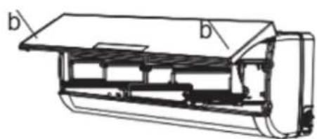
natural_image
Technical line drawing of a car air conditioner unit with labeled components (b), showing internal structure without any text or symbols.Thank you for purchasing this product!
I. INTRODUCTION
Before using the appliance, please read carefully this instruction manual and keep it for future reference.
This instruction manual is designed to provide you all required instructions related to the installation, use and maintenance of the appliance.
In order to operate the unit correctly and safety, please read this instruction manual carefully before installation and usage.
II. CONTENT OF YOUR PACKAGE

Air conditioner
User manual
➢ Remote controller manual
WIFI user manual (only models with WIFI)
Warranty card
➢ Installation kit (only models with installation kit)
III. SAFETY MEASURES
- To guarantee the unit work normally, please read the manual carefully before installation, and try to install strictly according to this manual.
- Do not let air enter the refrigeration system or discharge refrigerant when moving the air conditioner.
- Properly ground the air conditioner into the earth.
- Check the connecting cables and pipes carefully, make sure they are correct and firm before connecting the power of the air conditioner.
- There must be an air-break switch.
- After installing, the consumer must operate the air conditioner correctly according to this manual, keep a suitable storage for maintenance and moving of the air conditioner in the future.
- Fuse of indoor unit: T 3.15A 250VAC or T 5A 250VAC. Please refer to the screen printing on the circuit board for the actual parameters, which must be consistent with the parameters on the screen printing.
- For 7k\~12k models, fuse of outdoor unit: T 15A 250VAC or T 20A 250VAC. Please refer to the screen printing on the circuit board for the actual parameters, which must be consistent with the parameters on the screen printing.
- For 14K\~18k models, fuse of outdoor unit: T 20A 250VAC.
- For 21K\~36k models, fuse of outdoor unit: T 30A 250VAC.
- The installation instructions for appliances that are intended to be permanently connected to fixed wiring, and have a leakage current that may exceed 10 mA, shall state that the installation of a residual current device (RCD) having a rated residual operating current not exceeding 30 mA is advisable.
- Warning: Risk of electric shock can cause injury or death: Disconnect all remote electric power supplies before servicing.
- The maximum length of the connecting pipe between the indoor unit and outdoor unit should be less than 5 meters. It will affect the efficiency of the air conditioner if the distance longer than that length.
-
This appliance is not intended for use by person (including children) with reduced physical, sensory or mental capabilities, or lack of experience and knowledge, unless they have been given supervision or instruction concerning use of the appliance by a person responsible for their safety. Children should be supervised to ensure that they do not play with the appliance. Cleaning and user maintenance shall not be made by children without supervision.
-
This appliance can be used by children aged from 8 years and above and persons with reduced physical, sensory or mental capabilities or lack of experience and knowledge if they have been given supervision or instruction concerning use of the appliance in a safe way and understand the hazards involved. Children shall not play with the appliance. Cleaning and user maintenance shall not be made by children without supervision.
-
The batteries in remote controller must be recycled or disposed of properly. Disposal of Scrap Batteries. Please discard the batteries as sorted municipal waste at the accessible collection point.
-
If the appliance is fixed wiring, the appliance must be fitted with means for disconnection from the supply mains having a contact separation in all poles that provide full disconnection under over voltage category III conditions, and these means must be incorporated in the fixed wiring in accordance with the wiring rules.
-
If the supply cord is damaged, it must be replaced by the manufacturer, its service agent or similarly qualified persons in order to avoid a hazard.
-
The appliance shall be installed in accordance with national wiring regulations.
-
Servicing shall only be performed as recommended by the equipment manufacturer. Maintenance and repair requiring the assistance of other skilled personnel shall be carried out under the supervision of the person competent in the use of flammable refrigerants.
-
The appliance shall not be installed in the laundry.
-
Regarding to installation, please refer to section "Installation instructions".
-
Regarding to maintenance, please refer to section "Maintenance".
-
For models using R32 refrigerant, piping connection should be conducted on outdoor side.
IV. BEFORE USE
Note
- When charging refrigerant into the system, make sure to charge in liquid state, if the refrigerant of the appliance is R32. Otherwise, chemical composition of refrigerant (R32) inside the system may change and thus affect performance of the air conditioner.
- According to the character of refrigerant (R32, the value of GWP is 675), the pressure of the tube is very high, so be sure to be careful when you install and repair the appliance.
- If the supply cord is damaged, it must be replaced by the manufacturer, its service agent or similarly qualified persons in order to avoid a hazard.
- Installation of this product must be done by experienced service technician's professional installers only in accordance with this manual.
- The temperature of refrigerant circuit will be high, please keep the interconnection cable away from the copper tube.
Preset
Before using the air conditioner, be sure to check and preset the following.
- Remote Control presetting
Each time after the remote control is replaced with new batteries or is energized, remote control auto presetting heat pump. If the air conditioner you purchased is a Cooling Only one, heat pump remote controller can also be used.
- Back-light function of Remote Control (optional)
Hold down any button on remote control to activate the back light. It automatically shuts off 10 seconds later.
Note: Back-light is an optional function.
• Auto Restart Presetting
The air conditioner has an Auto-Restart function.
Safeguarding the environment
This appliance is made of recyclable or re-usable material. Scrapping must be carried out in compliance with local waste disposal regulations. Before scrapping it, make sure to cut off the mains cord so that the appliance cannot be re-used.
For more detailed information on handling and recycling this product, contact your local authorities who deal with the separate collection of rubbish or the shop where you bought the appliance.
V. USING INSTRUCTIONS
Symbols in this user manual are interpreted as shown below:

Be sure not to do.

Grounding is essential.

Pay attention to such.

Warning: incorrect handling could cause a serious hazard, serious injury, even death etc.

Use correct power supply in accordance with the rating plate requirement. Otherwise, serious faults or hazard may occur or a fire maybe break out.

Keep the power supply circuit breaker or plug from dirt. Connect the power supply cord to it firmly and correctly, leste an electric shock or a fire break out due to insufficient contact.

Do not use the power supply circuit breaker or pull off the plug to turn it off durign operation. This may cause a fire due to spark etc.

It is the user's responsibility to make the appliance be grounded according to local codes or ordinances by a licenced technician.

It is harmful to your health if the cool air reaches you for a long time. It is advisable to let the air flow be deflected to all the room.

Prevent the air flow from reaching the gas burners and stove. Do not touch the operations buttons when your hands are wet.

Turn off the appliance by remote control firstly before cutting off power supply if malfunction occurs.

Never insert a stick or similar obstacle to the unit. Since the fan rotates at high speed, this may cause an injury.

Do not repair the appliance by yourself. If this is done incorrectly, it may cause an electric shock etc. Do not put any objects on the outdoor unit.

Do not knit, pull or press the power supply cord, lest the power supply cord be broken. An electric shock or fire is probably caused by a broken power supply cord.
VI. SAFETY PRECAUTIONS FOR R32 REFRIGERANT
For the multi system, the refrigerant refer to the multi outdoor unit. The basic installation work procedures are the same as the conventional refrigerant (R22 or R410A). However, pay attention to the following points:

CAUTION
- Transport of equipment containing flammable refrigerants
Compliance with the transport regulations
- Marking of equipment using signs
Compliance with local regulations
- Disposal of equipment using flammable refrigerants
Compliance with national regulations
- Storage of equipment/appliances
The storage of equipment should be in accordance with the manufacturer's instructions.
- Storage of packed (unsold) equipment
Storage package protection should be constructed such that mechanical damage to the equipment inside the package will not cause a leak of the refrigerant charge.
The maximum number of pieces of equipment permitted to be stored together will be determined by local regulations.
- Information on servicing
6-1 Checks to the area
Prior to beginning work on systems containing flammable refrigerants, safety checks are necessary to ensure that the risk of ignition is minimised. For repair to the refrigerating system, the following precautions shall be complied with prior to conducting work on the system.
6-2 Work procedure
Work shall be undertaken under a controlled procedure so as to minimise the risk of flammable gas or vapour being present while the work is being performed.
6-3 General work area
All maintenance staff and others working in the local area shall be instructed on the nature of work being carried out. Work in confined spaces shall be avoided.
The area around the workspace shall be sectioned off. Ensure that the conditions within the area have been made safe by control of flammable material.
6-4 Checking for presence of refrigerant
The area shall be checked with an appropriate refrigerant detector prior to and during work, to ensure the technician is aware of potentially flammable atmospheres.
Ensure that the leak detection equipment being used is suitable for use with flammable refrigerants, i.e. non-sparking, adequately sealed or intrinsically safe.
6-5 Presence of fire extinguisher
If any hot work is to be conducted on the refrigeration equipment or any associated parts, appropriate fire extinguishing equipment shall be available to hand. Have a dry powder or CO2 fire extinguisher adjacent to the charging area.
6-6 No ignition sources
No person carrying out work in relation to a refrigeration system which involves exposing any pipe work that contains or has contained flammable refrigerant shall use any sources of ignition in such a manner that it may lead to the risk of fire or explosion. All possible ignition sources, including cigarette smoking, should be kept sufficiently far away from the site of installation, repairing, removing and disposal during which flammable refrigerant can possibly be released to the surrounding space. Prior to work taking place, the area around the equipment is to be surveyed to make sure that there are no flammable hazards or ignition risks. “No Smoking” signs shall be displayed.
6-7 Ventilated area
Ensure that the area is in the open or that it is adequately ventilated before breaking into the system or conducting any hot work.
A degree of ventilation shall continue during the period that the work is carried out. The ventilation should safely disperse any released refrigerant and preferably expel it externally into the atmosphere.
6-8 Checks to the refrigeration equipment
Where electrical components are being changed, they shall be fit for the purpose and to the correct specification.
At all times the manufacturer's maintenance and service guidelines shall be followed. If in doubt consult the manufacturer's technical department for assistance.
The following checks shall be applied to installations using flammable refrigerants:
- The charge size is in accordance with the room size within which the refrigerant containing parts are installed;
- The ventilation machinery and outlets are operating adequately and are not obstructed;
- If an indirect refrigerating circuit is being used, the secondary circuit shall be checked for the presence of refrigerant;
- Marking to the equipment continues to be visible and legible. Markings and signs that are illegible shall be corrected;
- Refrigeration pipe or components are installed in a position where they are unlikely to be exposed to any substance which may corrode refrigerant containing components, unless the components are constructed of materials which are inherently resistant to being corroded or are suitably protected against being so corroded.
6-9 Checks to electrical devices
Repair and maintenance to electrical components shall include initial safety checks and component inspection procedures.
If a fault exists that could compromise safety, then no electrical supply shall be connected to the circuit until it is satisfactorily dealt with.
If the fault cannot be corrected immediately but it is necessary to continue operation, an adequate temporary solution shall be used.
This shall be reported to the owner of the equipment so all parties are advised. Initial safety checks shall include:
- That capacitors are discharged: this shall be done in a safe manner to avoid possibility of sparking;
- That there no live electrical components and wiring are exposed while charging, recovering or purging the system;
– That there is continuity of earth bonding.
7. Repairs to sealed components
During repairs to sealed components, all electrical supplies shall be disconnected from the equipment being worked upon prior to any removal of sealed covers, etc.
If it is absolutely necessary to have an electrical supply to equipment during servicing, then a permanently operating form of leak detection shall be located at the most critical point to warn of a potentially hazardous situation.
Particular attention shall be paid to the following to ensure that by working on electrical components, the casing is not altered in such a way that the level of protection is affected.
This shall include damage to cables, excessive number of connections, terminals not made to original specification, damage to seals, incorrect fitting of glands, etc.
Ensure that apparatus is mounted securely.
Ensure that seals or sealing materials have not degraded such that they no longer serve the purpose of preventing the ingress of flammable atmospheres. Replacement parts shall be in accordance with the manufacturer's specifications.
NOTE:
The use of silicon sealant may inhibit the effectiveness of some types of leak detection equipment. Intrinsically safe components do not have to be isolated prior to working on them.
8. Repair to intrinsically safe components
Do not apply any permanent inductive or capacitance loads to the circuit without ensuring that this will not exceed the permissible voltage and current permitted for the equipment in use.
Intrinsically safe components are the only types that can be worked on while live in the presence of a flammable atmosphere. The test apparatus shall be at the correct rating.
9. Cabling
Check that cabling will not be subject to wear, corrosion, excessive pressure, vibration, sharp edges or any other adverse environmental effects.
The check shall also take into account the effects of aging or continual vibration from sources such as compressors or fans.
10. Detection of flammable refrigerants
Under no circumstances shall potential sources of ignition be used in the searching for or detection of refrigerant leaks. A halide torch (or any other detector using a naked flame) shall not be used.
11. Leak detection methods
The following leak detection methods are deemed acceptable for systems containing flammable refrigerants:
- Electronic leak detectors shall be used to detect flammable refrigerants, but the sensitivity may not be adequate, or may need re-calibration. (Detection equipment shall be calibrated in a refrigerant-free area.)
- Ensure that the detector is not a potential source of ignition and is suitable for the refrigerant used.
- Leak detection equipment shall be set at a percentage of the LFL of the refrigerant and shall be calibrated to the refrigerant employed and the appropriate percentage of gas (25 % maximum) is confirmed.
- Leak detection fluids are suitable for use with most refrigerants but the use of detergents containing chlorine shall be avoided as the chlorine may react with the refrigerant and corrode the copper pipe-work.
- If a leak is suspected, all naked flames shall be removed/ extinguished.
- If a leakage of refrigerant is found which requires brazing, all of the refrigerant shall be recovered from the system, or isolated (by means of shut off valves) in a part of the system remote from the leak.
- Oxygen free nitrogen (OFN) shall then be purged through the system both before and during the brazing process.
12. Removal and evacuation
When breaking into the refrigerant circuit to make repairs – or for any other purpose – conventional procedures shall be used.
However, it is important that best practice is followed since flammability is a consideration.
The following procedure shall be adhered to:
- Remove refrigerant;
- Purge the circuit with inert gas;
- Evacuate;
- Purge again with inert gas;
- Open the circuit by cutting or brazing.
The refrigerant charge shall be recovered into the correct recovery cylinders.
The system shall be "flushed" with OFN to render the unit safe. This process may need to be repeated several times.
Compressed air or oxygen shall not be used for this task.
Flushing shall be achieved by breaking the vacuum in the system with OFN and continuing to fill until the working pressure is achieved, then venting to atmosphere, and finally pulling down to a vacuum.
This process shall be repeated until no refrigerant is within the system. When the final OFN charge is used, the system shall be vented down to atmospheric pressure to enable work to take place. This operation is absolutely vital if brazing operations on the pipe-work are to take place. Ensure that the outlet for the vacuum pump is not close to any ignition sources and there is ventilation available.
13. Charging procedures
In addition to conventional charging procedures, the following requirements shall be followed:
- Ensure that contamination of different refrigerants does not occur when using charging equipment.
- Hoses or lines shall be as short as possible to minimise the amount of refrigerant contained in them.
- Cylinders shall be kept upright.
- Ensure that the refrigeration system is earthed prior to charging the system with refrigerant.
- Label the system when charging is complete (if not already).
- Extreme care shall be taken not to overfill the refrigeration system. Prior to recharging the system it shall be pressure tested with OFN.
The system shall be leak tested on completion of charging but prior to commissioning.
A follow up leak test shall be carried out prior to leaving the site.
14. Decommissioning
Before carrying out this procedure, it is essential that the technician is completely familiar with the equipment and all its detail.
It is recommended good practice that all refrigerants are recovered safely. Prior to the task being carried out, an oil and refrigerant sample shall be taken in case analysis is required prior to re-use of reclaimed refrigerant. It is essential that electrical power is available before the task is commenced.
a) Become familiar with the equipment and its operation.
b) Isolate system electrically.
c) Before attempting the procedure ensure that:
- Mechanical handling equipment is available, if required, for handling refrigerant cylinders;
– All personal protective equipment is available and being used correctly;
– The recovery process is supervised at all times by a competent person;
- Recovery equipment and cylinders conform to the appropriate standards.
d) Pump down refrigerant system, if possible.
e) If a vacuum is not possible, make a manifold so that refrigerant can be removed from various parts of the system.
f) Make sure that cylinder is situated on the scales before recovery takes place.
g) Start the recovery machine and operate in accordance with manufacturer's instructions.
h) Do not overfill cylinders. (No more than 80 % volume liquid charge).
I) Do not exceed the maximum working pressure of the cylinder, even temporarily.
j) When the cylinders have been filled correctly and the process completed, make sure that the cylinders and the equipment are removed from site promptly and all isolation valves on the equipment are closed off.
k) Recovered refrigerant shall not be charged into another refrigeration system unless it has been cleaned and checked.
15. Labelling
Equipment shall be labelled stating that it has been de-commissioned and emptied of refrigerant.
The label shall be dated and signed.
Ensure that there are labels on the equipment stating the equipment contains flammable refrigerant.
16. Recovery
When removing refrigerant from a system, either for servicing or decommissioning, it is recommended good practice that all refrigerants are removed safely.
When transferring refrigerant into cylinders, ensure that only appropriate refrigerant recovery cylinders are employed.
Ensure that the correct number of cylinders for holding the total system charge is available.
All cylinders to be used are designated for the recovered refrigerant and labelled for that refrigerant (i.e. special cylinders for the recovery of refrigerant).
Cylinders shall be complete with pressure relief valve and associated shut-off valves in good working order.
Empty recovery cylinders are evacuated and, if possible, cooled before recovery occurs.
The recovery equipment shall be in good working order with a set of instructions concerning the equipment that is at hand and shall be suitable for the recovery of flammable refrigerants.
In addition, a set of calibrated weighing scales shall be available and in good working order.
Hoses shall be complete with leak-free disconnect couplings and in good condition.
Before using the recovery machine, check that it is in satisfactory working order, has been properly maintained and that any associated electrical components are sealed to prevent ignition in the event of a refrigerant release. Consult manufacturer if in doubt.
The recovered refrigerant shall be returned to the refrigerant supplier in the correct recovery cylinder, and the relevant Waste Transfer Note arranged. Do not mix refrigerants in recovery units and especially not in cylinders.
If compressors or compressor oils are to be removed, ensure that they have been evacuated to an acceptable level to make certain that flammable refrigerant does not remain within the lubricant.
The evacuation process shall be carried out prior to returning the compressor to the suppliers.
Only electric heating to the compressor body shall be employed to accelerate this process.
When oil is drained from a system, it shall be carried out safely.
When moving or relocating the air conditioner, consult experienced service technicians for disconnection and reinstallation of the unit.
Do not place any other electrical products or household belongings under indoor unit or outdoor unit. Condensation dripping from the unit might get them wet, and may cause damage or malfunction of your property.
Do not use means to accelerate the defrosting process or to clean, other than those recommended by the manufacturer.
The appliance shall be stored in a room without continuously operating ignition sources (for example, open flames, an operating gas appliance or an operating electric heater).
Do not pierce or burn.
Be aware that refrigerants may not contain an odour. To keep ventilation openings clear of obstruction.
The appliance shall be stored in a well-ventilated area where the room size corresponds to the room area as specified for operation.
The appliance shall be stored in a room without continuously operating open flames (for example an operating gas appliance) and ignition sources (for example an operating electric heater).
Any person who is involved with working on or breaking into a refrigerant circuit should hold a current valid certificate from an industry-accredited assessment authority, which authorises their competence to handle refrigerants safely in accordance with an industry recognised assessment specification.
Servicing shall only be performed as recommended by the equipment manufacturer.
Maintenance and repair requiring the assistance of other skilled personnel shall be carried out under the supervision of the person competent in the use of flammable refrigerants.
Do not use means to accelerate the defrosting process or to clean, other than those recommended by the manufacturer.
Appliance shall be installed, operated and stored in a room with a floor area larger than 10 m2.
The installation of pipe-work shall be kept to a room with a floor area larger than 10 m2.
The pipe-work shall be compliance with national gas regulations.
The maximum refrigerant charge amount is 2.5 kg. The specific refrigerant charge is based on the nameplate of the outdoor unit.
Mechanical connectors used indoors shall comply with ISO 14903. When mechanical connectors are reused indoors, sealing parts shall be renewed. When flared joints are reused indoors, the flare part shall be re-fabricated. The installation of pipe-work shall be kept to a minimum.
Mechanical connections shall be accessible for maintenance purposes.
Explanation of symbols displayed on the indoor unit or outdoor unit
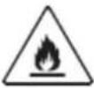 | WARNING | This symbol shows that this appliance used a flammable refrigerant. If the refrigerant is leaked and exposed to an external ignition source, there is a risk of fire. |
 | CAUTION | This symbol shows that the operation manual should be read carefully. |
 | CAUTION | This symbol shows that a service personnel should be handling this equipment with reference to the installation manual. |
 | CAUTION | |
 | CAUTION | This symbol shows that information is available such as the operating manual or installation manual. |
VII. INSTALLATION INSTRUCTIONS

Location for installing indoor unit
- Where there is no obstacle near the air outlet and air can be easily blown to every corner.
- Where piping and wall hole can be easily arranged.
- Keep the required space from the unit to the ceiling and wall according to the installation diagram on previous page.
- Where the air filter can be easily removed.
- Keep the unit and remote controller 1m or more apart from television, radio etc.
- Keep as far as possible from fluorescent lamps.
- Do not put anything near the air inlet to obstruct it from air absorption.
- Install on a wall that is strong enough to bear the weight of the unit. Install in a place that will not increase operation noise and vibration. Keep away from direct sunlight and heating sources. Do not place flammable materials or combustion apparatuses on top of the unit.
Location for installing outdoor unit
- Where it is convenient to install and well ventilated. Avoid installing it where flammable gas could leak. Keep the required distance apart from the wall.
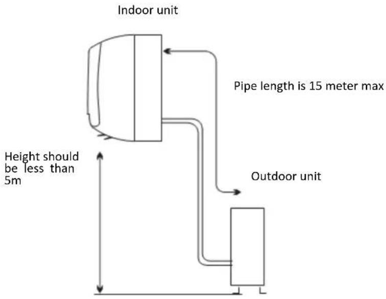
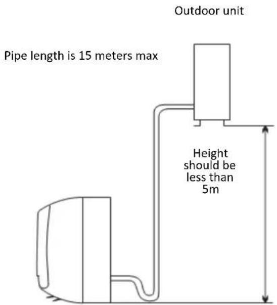
- The pipe length between indoor and outdoor unit should be not more than 5 meters in factory default status, but it can go up to maximum 15 meters with additional refrigerant charge.
- Keep the outdoor unit away from greasy dirt, vulcanization gas exit.
- Avoid installing it by the roadside where there is a risk of muddy water.
- A fixed base where it is not a subject to increased operation noise.
- Where there is not any blockage of the air outlet.
- Avoid installing under direct sunlight, in an aisle or sideway, or near heat sources and ventilation fans. Keep away from flammable materials, thick oil fog and wet or uneven places.
Indoor unit
| Model | Max allowed pipe length without additional refrigerant (m) | Limit of pipe length (m) | Limit of elevation difference H (m) | Required amount of additional refrigerant (g/m) |
| 7k~18k | 5 | 15 | 5 | 20 |
| 21k~25k | 5 | 15 | 5 | 30 |
| 25k~36k | 5 | 15 | 5 | 40 |
If the height or pipe is out of the scope of the table, please consult the producer.
3. Installing the mounting plate
- Decide an installing location for the mounting plate according to the indoor unit location and pipe direction. Keep the mounting. Plate horizontally with a horizontal ruler or level.
- Drill holes of 32mm in depth on the wall for fixing the plate.
- Insert the plastic plugs to the hole, fix the mounting plate with tapping screws. Inspect if the mounting plate is well fixed. Then drill a hole for pipe.
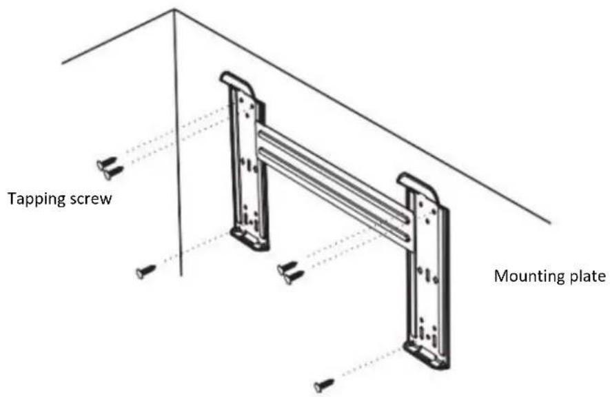
Note: the shape of your mounting plate may be different from the one above, but the installation method is similar.
Note: as the above figure shown, the six holes matched with tapping screw on the mounting plate must be used to fix the mounting plate, the others are prepared.
4. Drill a hole for pipe
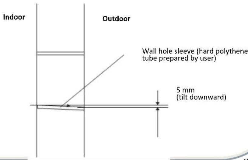
- Decide the position of hole for pipe according to the location of mounting plate.
- Drill a hole on the wall about 50 mm. The hole should tilt a little downward toward outside.
• Install a sleeve through the wall hole to keep the wall tidy and clean.
3. Indoor unit pipe installation
- Put the pipes (liquid and gas pipe) and cables through the wall hole from outside or put them through from inside after indoor pipe and cables connection complete so as to connect to outdoor unit.
- Decide whether saw the unloading piece off in accordance with the pipe direction. (as shown below).

Note: when installing the pipe at the directions 1,2 or 4, saw the corresponding unloading piece off the undoor unit base.
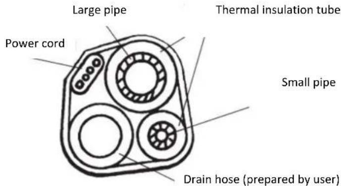
- After connecting pipe as required, install the drain hose. Then connect the power cords. After connecting, wrap the pipes, cords and drain hose together with thermal insulation materials.

- Pipe joints thermal insulation: Wrap the pipes joints with thermal insulation materials and then wrap with a vinyl tape.
- Pipes thermal insulation:
c. Place the drain hose under the pipes
d. Insulation material uses polythene foam over 6mm in thickness.
Note: drain hose is prepared by user.
- Drain pipe should point downward for easy drain flow. Do not arrange the drain pipe twisted, sticking out or wave around, do not immerse the end of it in water.
- If an extension drain hose is connected to the drain pipe, make sute to thermal insulated when passing along the indoor unit.
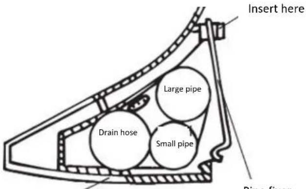
- When the pipes is directed to the right, pipes, power cord and drain pipe should be thermal insulated and fixed onto the back of the unit with a pipe fixer.

natural_image
Cross-sectional diagram of a portable electronic device with internal components and mounting base (no text or symbols)Base
Pipe fixer
Pipe fixer
Base

Base
Hook here
A. Insert the pipe fixer to the slot.
B. Press to hook the pipe fixer onto the base.
Piping connection:
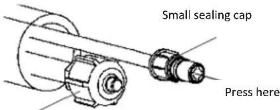
a. Before unscrewing the big and the small sealing caps, press the small sealing cap with the finger until the exhaust noise stops, and then loosen the finger.
b. Connect indoor unit pipes with two wrenches. Pay special attention to the allowed torque as shown below to prevent the pipes, connectors and flare nuts from being deformed and damaged.
c. Pre-tighten them with fingers at first, then use the wrenches. If you don't hear the exhaust noise, please contact with the merchant.
Big sealing cap
| Model | Pipe size | Torque | Nut width | Min.thickness |
| 7k~12K, 13k~18K, 22K | Liquid Side (φ6mm or 1/4 inch) | 15~20N·m | 17mm | 0.5mm |
| 18K', 21K~36K | Liquid Side (φ9.53mm or 3/8 inch) | 30~35N·m | 22mm | 0.6mm |
| 7K~13K | Gas Side (φ9.53mm or 3/8 inch) | 30~35N·m | 22mm | 0.6mm |
| 12K', 13K~18K | Gas Side (φ12mm or 1/2 inch) | 50~55N·m | 24mm | 0.6mm |
| 18K', 21K~36K | Gas Side (φ16mm or 5/8 inch) | 60~65N·m | 27mm | 0.6mm |
| 36K' | Gas Side (φ19mm or 3/4 inch) | 70~75N·m | 32mm | 1.0mm |
Note: the unit 12k#, 18k# and 36k# is bigger than the unit of 12k, 18k and 36k.
Note: piping connection should be conducted on outdoor side.
4. Connecting the cable
- Indoor unit
Connect the power cord to the indoor unit by connecting the wires to the terminals on the control board individually in accordance with the outdoor unit connection.
Note: for some models, it is necessary to remove the cabinet to connect to the indoor unit terminal.
- Outdoor unit
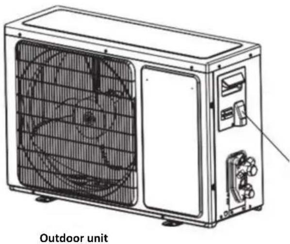
e. Remove the access door from the unit by loosening the screw. Connect the wires to the terminals on the control board individually as follows.
f. Secure the power cord onto the control board with cable clamp.
g. Reinstall the access door to the original position with the screw.
h. Use a recognized circuit breaker for 24K model between the power source and the unit. A disconnecting device to adequately disconnect all supply lines must be fitted.

natural_image
Line drawing of an outdoor air conditioner unit with fan blades and control panel (no text or symbols on the device itself)Access door terminal (inside)
Caution:
- Never fail to have an individual power circuit specifically for the air conditioner. As for the method of wiring, refer to the circuit diagram posted on the inside of the access door.
- Comfirm that the cable thickness is as specified in the power source specification.
- Check the wires and make sure that they are all tightly fastened after cable connection.
- Be sure to install an earth leakage circuit breaker in wet or moist areas.
Cable specifications
| Capacity (Btu/h) | Power cord | Power connecting cord | ||
| Type | Normal cross - sectional area | Type | Normal cross - sectional area | |
| 7K~12K | H07RN-F | 1.0/1.5mm^3X3 | H05RN-F | 0.75mm^2X4 |
| H07RN-F | 1.0/1.5mm^3X3 | H07RN-F | 1.0/1.5mm^2X5 | |
| 7K*~12K* | H05VV-F | 1.0/1.5mm^3X3 | H07RN-F | 1.0/1.5mm^2X4 |
| CIRCULAR 1100V YY IS:694 | 1.0/1.5mm^3X3 | H07RN-F | 1.0/1.5mm^2X4 | |
| 14K~18K | H07RN-F | 1.5mm^3X3 | H05RN-F | 0.75mm^2X4 |
| H07RN-F | 1.5mm^3X3 | H07RN-F | 1.5mm^2X5 | |
| 14K*~18K* | H05VV-F | 1.5/2.5mm^2X3 | H07RN-F | 1.5/2.5mm^2X4 |
| CIRCULAR 1100V YY IS:694 | 1.5/2.5mm^2X3 | H07RN-F | 1.5/2.5mm^2X4 | |
| 21K~36K | H07RN-F | 2.5mm^3X3 | H05RN-F | 0.75mm^2X4 |
| H07RN-F | 2.5mm^2X3 | H07RN-F | 1.0mm^2X4 | |
| H07RN-F | 2.5mm^2X3 | H07RN-F | 2.5mm^2X5 | |
| 21K*~30K* | H05VV-F | 2.5mm^3X3 | H07RN-F | 2.5mm^2X4 |
| 21K**~24K** | H05VV-F | 1.5mm^2X3 | H07RN-F | 1.5mm^2X4 |
Note:
1.K* means the power supply of this model comes from indoor unit.
2. K** indicates indoor power supply unit model with power line and plug.
3. For 14K^ 18K^ models under Tropical(T3) Climate condition, the normal cross-sectional area of Power cord and Power connecting cord is 2.5mm2× 4 .
Attention:
The plug must be accessible even after the installation of the appliance in case there is a need to disconnect it. if not possible, connect appliance to a double-pole switching device with contact separation of at least 3mm placed in an accessible position even after installation.
VIII. MAINTENANCE
Front panel maintenance
-
Cut off the power supply. Turn off ht eappliance first beofre disconnecting from power supply.
-
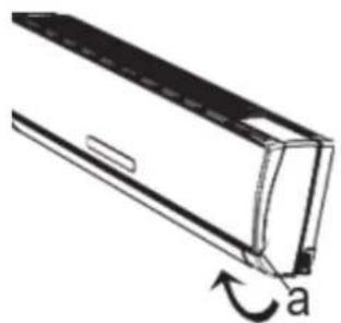
Grasp position "a" and pull outward to remove the front panel.
-
Wipe with a soft and dry cloth. Use soft moisture cloth to clean if the front panel is very dirty.
-
Never use volatile substance such as gasoline or polishing powder to clean the appliance.
-
Never sprinkle water onto the indoor unit.
-
Reinstall and shut the front panel. Reinstall and shut the front panel by pressing position "b" downward.
natural_image
Diagram of a car air conditioner unit with a curved arrow indicating rotation (no text or symbols)
natural_image
Technical line drawing of a car air conditioner unit with labeled components (b), showing internal structure without any text or symbols.Air filter maintenance
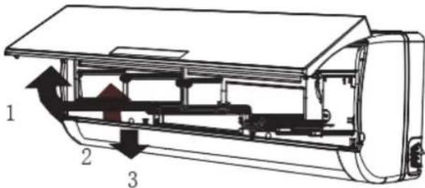
- Stop the appliance, cut oof the power supply and remove the air filter.
a. Open the front panel.
b. Press the handle of the filter gently from the front.
c. Grasp the handle and slide out the filter.
- Clean and reinstall the air filter.
If the dirt is conspicuous, wash it with a solution of detergent in lukewarm water. After cleaning, dry well in shade.
- Close the front panel again.
Clean the air filter every two weeks if the ar conditioner operates in an extremely dusty environment.
It is necessary to clean the air filter after using it for about 100 hours.
IX. OPERATING CONDITION
Operating temperature
| Temperature | Cooling operation | Heating operation | Drying operation | |
| Indoor temperature | max | 32°C | 27°C | 32°C |
| min | 21°C | 7°C | 18°C | |
| Outdoor temperature | max | 43°C | 24°C | 43°C |
| min | *note | -15°C | 21°C | |
NOTE:
*Optimum performance will be achieved within these operating temperature. If air conditioner is used outside of the above conditions, the protective device may trip and stop the appliance.
*For Tropical (T3) Climate condition models, the outdoor max temperature is 55°C instead of 43°C.
*For some models, can keep cooling at -15°C outdoor ambient via unique design. Normally, optimum cooling performance will be achieved above 21°C. Please consult the merchant to get more information.
*For some models, can keep heating at -15°C outdoor ambient, some models heat at -20°C outdoor ambient,
even heat at lower outdoor ambient
The temperature of some products is allowed beyond the range. In specific situation, please consult the merchant. When relative humidity is above 80%, if the air conditioner runs in COOLING or DRY mode with door or window opened for a long time, dew may drip down from the outlet.
Noise pollution
- Install the air conditioner at a place that can bear its weight in ordre to operate more quietly.
- Install the outdoor unit at a place where the air discharged and the operation noise would not annoy your neighbours.
- Do not place any obstacles in front of the air outlet of the outdoor unit lest is increases the noise level.
Features of protector
- The protective device will work at following cases.
- Restarting the unit at once after operation stops or changing mode during operation, you need to wait for 3 minutes.
- Connect to power supply and turn on the unit at once, it may strat 20 seconds later.
- If all operation has stopped, press ON/OFF button again to restart, timer should be set again if it has been canceled.
Features of HEATING mode
PREHEAT
At the beginning of the HEATING operation, the airflow from the indoor unit is discharged 2-5 minutes later.
DEFROST
In HEATING operation the appliance will deforst (de-ice) automatically to raise efficiency. This procedure usually lasts 2-10 minutes. During defrosting, fans stop operation. After defrosting completes, it return to HEATING mode automatically.
Note: Heating is NOT available for cooling only air conditioner models.
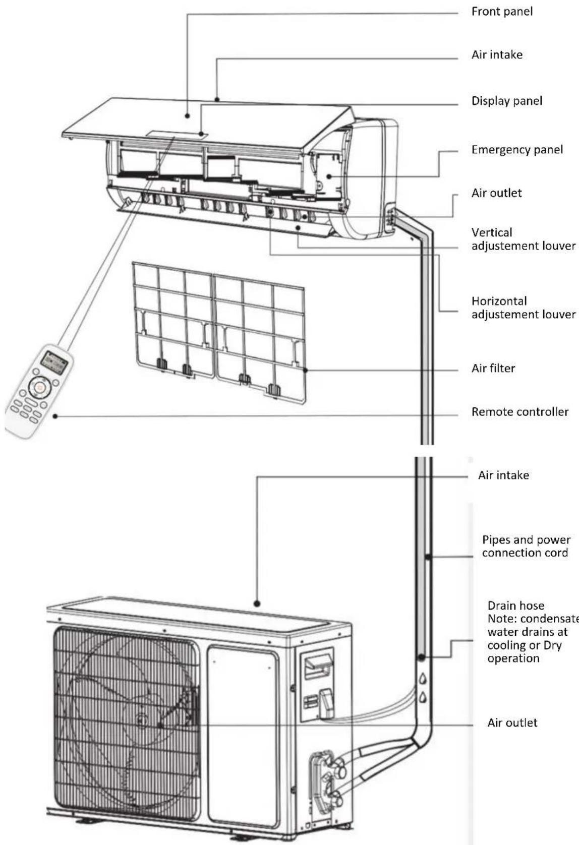
X. PRODUCT DESCRIPTION
XI. DISPLAY

Temperature indicator
Display set temperature. It shows FC after 200 hours of usage as reminder to clean the filter. After cleaning press the filter reset button located on the indoor unit behind the front panel in order to reset the display (optional)


Running indicator
It lights up when the AC is running. It flashes during defrosting


Timer indicator
It lights up during set time


Sleep indicator
It lights up in sleep mode


Compressor indicator
It lights up when the compressor is on

Mode indicator
Heating displays orange, others display white

Fan speed indicator
Smart WIFI indicator
It lights up during WIFI is on


NANOE indicator
It lights up in NANOE mode

FAN ONLY mode indicator
It lights up in FAN ONLY mode
XII. TROUBLESHOOTING
The following case may not always be a malfunction, please check it before asking for service.
| Trouble | Analysis |
| Does not run | If the protector trip or fuse is blown. Please wait for 3 minutes and start again, protector device may be preventing unit to work.If batteries in the remote controller exhausted.If the plug is not properly plugged. |
| No cooling or heating air | Is the air filter dirty?Are the intakes and outlets of the air conditioner blocked?Is the temperature set properly? |
| Ineffective control | If strong interference (from excessive static electricity discharge, power supply voltage abnormality) presents, operation will be abnormal. At this time, disconnect from the power supply and connect back 2-3 seconds later. |
| Does not operate immediately | Changing mode during operation, 3 minutes will delay. |
| Peculiar odor | This odor may come from another source such as furniture, cigarette etc, which is sucked in the unit and blows out with the air. |
| A sound of flowing water | Caused by the flow of refrigerant in the air conditioner, not a trouble.Defrosting sound in heating mode. |
| Cracking sound is heard | The sound may be generated by the expansion or contraction of the front panel due to change of temperature. |
| Spay mist from the outlet | Mist appears when the room air becomes very cold because of cool air discharged from indoor unit during COOLING or DRY operation mode. |
| The compressor indicator (red) lights on constantly and indoor fan stops | The unit is shifting from heating mode to defrost. The indicator will lights off within ten minutes and returns to heating mode. |
XIII. TECHNICAL DETAILS
| HAC-HS09KIT++HAC-HS09WH++ | HAC-HS12KIT++HAC-HS12WH++HAC-HS12WIFI++ | HAC-HS18KIT++HAC-HS18WH++HAC-HS18WIFI++ | HAC-HS24KIT++HAC-HS24WH++HAC-HS24WIFI++ | |
| Power | 190-1500 W | 190-1600 W | 260-2300 W | 420-2760 W |
| Voltage | 220-240V, 50Hz | 220-240V, 50Hz | 220-240V, 50Hz | 220-240V, 50Hz |
| Cooling | 9000 BTU | 12000 BTU | 18000 BTU | 24000 BTU |
| Noise level | 56/62dB | 56/62dB | 59/63dB | 63/64dB |
| Color | White | White | White | White |

Environment friendly disposal
You can help protect the environment!
Please remember to respect the local regulations: hand in the non-working electrical equipment's to an appropriate waste disposal center.

HEINNER is a registered trademark of Network One Distribution SRL. Other brands and product names are trademarks or registered trademarks of their respective holders.
No part of the specifications may be reproduced in any form or by any means or used to make any derivative such as translation, transformation, or adaptation without permission from NETWORK ONE DISTRIBUTION.
Copyright © 2013 Network One Distribution. All rights reserved.
www.heinner.com, http://www.nod.ro
CE
This product is in conformity with norms and standards of European Community.
Importer: Network One Distribution
Marcel Iancu Street, 3-5, Bucharest, Romania
Tel: +40 21 211 18 56, www.heinner.com, www.nod.ro
HEINNER
КЛИМАТИК
Модел:
HAC-HS09KIT++/HAC-HS09WH++
HAC-HS12KIT++/HAC-HS12WH++/HAC-HS12WIFI++
HAC-HS18KIT++/HAC-HS18WH++/HAC-HS18WIFI++
HAC-HS24KIT++/HAC-HS24WH++/HAC-HS24WIFI++
- Климатик
• Капацитет: 9000 / 12000 / 18000 / 24000 BTU
• Цвят: бял
natural_image
Cross-sectional diagram of a device with internal components and mounting base (no text or symbols)natural_image
Line drawing of a multi-chamber air conditioning unit with fan blades and control panel (no text or symbols)natural_image
Technical line drawing of a car air conditioner unit showing internal components and airflow direction (no text or symbols)natural_image
Line drawing of a car air conditioner unit with a curved arrow indicating rotation (no text or symbols)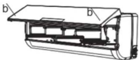
natural_image
Technical line drawing of a car air conditioner unit with labeled components (b), showing internal structure without any text or symbols.- Thank you for purchasing this product!
- INTRODUCTION
- CONTENT OF YOUR PACKAGE
- SAFETY MEASURES
- BEFORE USE
- Note
- Preset
- - Remote Control presetting
- - Back-light function of Remote Control (optional)
- • Auto Restart Presetting
- Safeguarding the environment
- USING INSTRUCTIONS
- Symbols in this user manual are interpreted as shown below:
- SAFETY PRECAUTIONS FOR R32 REFRIGERANT
- CAUTION
- 6-5 Presence of fire extinguisher
- 6-6 No ignition sources
- 6-7 Ventilated area
- 6-8 Checks to the refrigeration equipment
- 6-9 Checks to electrical devices
- Repairs to sealed components
- NOTE:
- Repair to intrinsically safe components
- Cabling
- Detection of flammable refrigerants
- Leak detection methods
- Removal and evacuation
- Charging procedures
- Decommissioning
- Labelling
- Recovery
- INSTALLATION INSTRUCTIONS
- Location for installing indoor unit
- Location for installing outdoor unit
- Installing the mounting plate
- Drill a hole for pipe
- Indoor unit pipe installation
- Piping connection:
- Connecting the cable
- - Indoor unit
- - Outdoor unit
- Caution:
- Attention:
- MAINTENANCE
- Front panel maintenance
- Air filter maintenance
- OPERATING CONDITION
- Noise pollution
- Features of protector
- Features of HEATING mode
- PREHEAT
- DEFROST
- PRODUCT DESCRIPTION
- DISPLAY
- Temperature indicator
- Running indicator
- Timer indicator
- Sleep indicator
- Compressor indicator
- Mode indicator
- Fan speed indicator
- Smart WIFI indicator
- NANOE indicator
- FAN ONLY mode indicator
- TROUBLESHOOTING
- TECHNICAL DETAILS
- Environment friendly disposal
- HEINNER
- КЛИМАТИК
Brand : Heinner
Model : HAC-HS09WH++
Category : Air conditioner