
A960M-MV - Motherboard ECS - Free user manual and instructions
Find the device manual for free A960M-MV ECS in PDF.


| Product Type | Motherboard |
| Brand | ECS |
| Model | A960M-MV |
| CPU Socket | AM3+ |
| Chipset | AMD 760G + SB710 |
| Form Factor | Micro-ATX |
| Dimensions | 244 x 244 mm |
| Memory Type | DDR3 |
| Number of Memory Slots | 2 |
| Supported Memory Frequency | Up to 1333 MHz (OC 1600 MHz) |
| Maximum Memory Capacity | 16 GB |
| Required Power Supply | ATX 24-pin + 4-pin CPU (≥300W recommended) |
| Storage Connectors | 6 x SATA 3.0 Gb/s |
| IDE Connector | 1 x IDE (PATA) |
| Expansion Slots | 1 x PCIe x16, 1 x PCIe x1, 2 x PCI |
| Audio | 6-channel HD Audio |
| Network | 1 x Gigabit Ethernet LAN |
| Rear USB Ports | 4 x USB 2.0 |
| Video Ports | 1 x VGA, 1 x DVI |
| Key Features | Supports AM3+ AMD FX, Phenom II, Athlon II; BIOS with EZ-Flash functions |
| Maintenance and Cleaning | Regular dusting with dry compressed air; avoid humidity |
| Safety Precautions | Avoid electrostatic discharge; disconnect power before handling |
| Spare Parts and Repairability | CR2032 CMOS battery, removable CPU cooler, user manual |
| General Information | 2-year warranty; complies with Canada Class B |
Frequently Asked Questions - A960M-MV ECS
User questions about A960M-MV ECS
0 question about this device. Answer the ones you know or ask your own.
Ask a new question about this device
Download the instructions for your Motherboard in PDF format for free! Find your manual A960M-MV - ECS and take your electronic device back in hand. On this page are published all the documents necessary for the use of your device. A960M-MV by ECS.
USER MANUAL A960M-MV ECS
This publication, including all photographs, illustrations and software, is protected under international copyright laws, with all rights reserved. Neither this manual, nor any of the material contained herein, may be reproduced without written consent of the author.
Version 1.0
✿✿✿✿✿○✿]
The information in this document is subject to change without notice. The manufacturer makes no representations or warranties with respect to the contents hereof and specifically disclaims any implied warranties of merchantability or fitness for any particular purpose. The manufacturer reserves the right to revise this publication and to make changes from time to time in the content hereof without obligation of the manufacturer to notify any person of such revision or changes.
\*□\*\*○\*\*]\*\*\*□■■□■
Microsoft, MS-DOS and Windows are registered trademarks of Microsoft Corp.
AMD, Phenom, Athlon, Sempron, Turion, and Duron are registered trademarks of AMD Corporation.
Other product names used in this manual are the properties of their respective owners and are acknowledged.
◆※※□●◆□○○◆■※※▼□■▲◆□○○▲▲□■◆◆
This equipment has been tested and found to comply with the limits for a Class B digital device, pursuant to Part 15 of the FCC Rules. These limits are designed to provide reasonable protection against harmful interference in a residential installation. This equipment generates, uses, and can radiate radio frequency energy and, if not installed and used in accordance with the instructions, may cause harmful interference to radio communications. However, there is no guarantee that interference will not occur in a particular installation. If this equipment does cause harmful interference to radio or television reception, which can be determined by turning the equipment off and on, the user is encouraged to try to correct the interference by one or more of the following measures:
- Reorient or relocate the receiving antenna
- Increase the separation between the equipment and the receiver
- Connect the equipment onto an outlet on a circuit different from that to which the receiver is connected
- Consult the dealer or an experienced radio/TV technician for help
Shielded interconnect cables and a shielded AC power cable must be employed with this equipment to ensure compliance with the pertinent RF emission limits governing this device. Changes or modifications not expressly approved by the system's manufacturer could void the user's authority to operate the equipment.
This device complies with part 15 of the FCC rules. Operation is subject to the following conditions:
• This device may not cause harmful interference.
- This device must accept any interference received, including interference that may cause undesired operation.
This device is in conformity with the following EC/EMC directives:
☐ EN 55022 Limits and methods of measurement of radio disturbance characteristics of information technology equipment
☐ EN 61000-3-2 Disturbances in supply systems caused
☐ EN 61000-3-3 Disturbances in supply systems caused by household appliances and similar electrical equipment “Voltage fluctuations”
☐ EN 55024 Information technology equipment-Immunity characteristics-Limits and methods of measurement
☐ EN 60950 Safety for information technology equipment including electrical business equipment
□ CE marking CE
◆■□○○■□○○◆■□▲
This class B digital apparatus meets all requirements of the Canadian Interference-causing Equipment Regulations.
The manual consists of the following:
Chapter 1 Describes features of the page 1 Introducing the Motherboard motherboard.
Chapter 2 Provides information on us- page 7 Using BIOS ing the BIOS Setup Utility.
Chapter 3 Describes the motherboard page 33 Using the Motherboard Software software.
Chapter 4 Provides basic trouble page 39 Trouble Shooting shooting tips.
Multi-language Describes installation of page 43 Quick Installation Guide motherboard components.
Appendix Provides header pin definition→ page 77 and jumper settings.
TABLE OF CONTENTS
Preface i
Chapter 1 1
Introducing the Motherboard 1
Introduction....1
Pakage Contents....1
Specifications....2
Motherboard Components....4
I/O Ports....6
Chapter 2 7
Using BIOS 7
About the Setup Utility....7
The Standard Configuration....7
Entering the Setup Utility....7
Resetting the Default CMOS Values....8
Using BIOS....8
BIOS Navigation Keys....9
Main Menu....9
Advanced Menu....10
Chipset Menu....20
M.I.B. III (MB Intelligent BIOS III) Menu....22
Boot Menu....27
Security Menu....29
Exit Menu....30
Updating the BIOS....31
Chapter 3 33
Using the Motherboard Software 33
Auto-installing under Windows XP/7/8....33
Running Setup....33
Manual Installation....35
ECS Utility Software....35
Chapter 4 39
Trouble Shooting 39
Start up problems during assembly....39
Start up problems after prolong use....40
Maintenance and care tips....40
Basic Troubleshooting Flowchart....41
Multi-language Quick Installation Guide 43
English....43
Brazilian Portuguese....46
Hindi....49
French....52
Deutsch....55
Russian....58
Spanish....61
Indonesian....64
Arabic....67
Simplified Chinese....70
Korean....73
Appendix 77
Header Pin Definition and Jumper Settings 77
Chapter 1
Introducing the Motherboard
Introduction
Thank you for choosing the A960M-MV motherboard. This motherboard is a high performance, enhanced function motherboard that supports socket AM3/AM3+ for AMD FX™/Phenom™ II/Athlon™II/Sempron™ 100 series processors for high-end business or personal desktop markets.
The motherboard is based on AMD 760G (RS780L) Northbridge (NB) and SB710 Southbridge (SB) chipsets. The memory controller supports DDR3 memory DIMM frequencies of 1866(OC)/1600/1333/1066. It supports two DDR3 slots with maximum memory size of 16 GB. One PCI Express x16 slot, intended for Graphics Interface, is fully compliant to the PCI Express Gen2. In addition, one PCI Express x1 slot is supported.
The SB710 Southbridge integrates USB 2.0 interface, supporting up to eight USB 2.0 ports (four USB 2.0 ports at the rear panel and two USB 2.0 headers support additional four USB 2.0 ports). It also integrates a Serial ATA host controller, supporting four SATA ports with maximum transfer rate up to 3Gb/s each.
There is an advanced full set of I/O ports in the rear panel, including PS/2 mouse and keyboard connectors, four USB 2.0 ports, one LAN port, one D-sub (VGA) port, one HDMI port (optional) and audio jacks for microphone, line-in and line-out.
Package Contents
Your motherboard package ships with the following items:
A960M-MV Motherboard
□ User Manual
DVD
□ I/O Shield
2 SATA 3Gb/s Cables

The package contents above are for reference only, please take the actual package items as standard.
Specifications
| CPU | supports socket AM3/AM3+ for AMD FXTM/PhenomTM II/AthlonTMII/SempronTM 100 series processorsSupports CPU up to 95W TDPNote: Please go to ECS website for the latest CPU support list. |
| Chipset | NB: AMD 760GSB: AMD SB710 |
| Memory | Dual-channel DDR3 memory architecture2 x 240-pin DDR3 DIMM sockets support up to 16 GBSupports DDR3 1866(OC)/1600/1333/1066 MHz DDR3 SDRAMNote: Please go to ECS website for the latest memory support list. |
| Expansion Slots | 1 x PCI Express x16 Gen2 slot1 x PCI Express x1 slot |
| Storage | Supported by AMD SB710 Express Chipset- 4 x Serial ATA 3Gb/s connectors |
| Audio | Realtek ALC 662 6 channel High Definition audio CODEC- Compliant with HD audio specification |
| LAN | RTL8105E 10/100 LANRTL8111E Gigabit LAN (optional) |
| Rear Panel I/O | 1 x PS/2 keyboard and PS/2 mouse connectors4 x USB 2.0 ports1 x RJ45 LAN connector1 x HDMI port (optional)1 x D-sub (VGA) port1 x Audio port (Line in, microphone and Line out) |
| Internal I/OConnectors & Headers | 1 x 24-pin ATX Power Supply connector1 x 4-pin 12V Power connector1 x 4-pin CPU_FAN connector1 x 3-pin SYS_FAN connector2 x USB 2.0 headers support additional four USB 2.0 ports4 x Serial SATA 3Gb/s connectors1 x COM header1 x Case open header1 x Front Panel audio header1 x Front Panel switch/LED header1 x Speaker header1 x Clear CMOS jumper1 x Front panel USB power select jumper1 x Rear USB/PS2 power select jumper |
| System BIOS | • AMI BIOS with 16Mb SPI Flash ROM- Supports Plug and Play, S1/STR S3/STD S4- Supports ACPI & DMI- Supports Hardware Monitor- Audio, LAN, can be disabled in BIOS- F7 hot key for boot up devices option- Supports Over-Clocking- Supports PaUp clear CMOS Hotkey (Has PS2 KB Model only)- Supports Dual Display- Supports UEFI BIOS- Supports AC'97/HD Audio auto detect |
| AP Support | • Supports eOC/eBLU*/eDLU/eSF*Note: *Microsoft .NET Framework 3.5 is required. |
| Form Factor | • Micro ATX Size, 210mm x 180mm |

Chapter 1
Motherboard Components
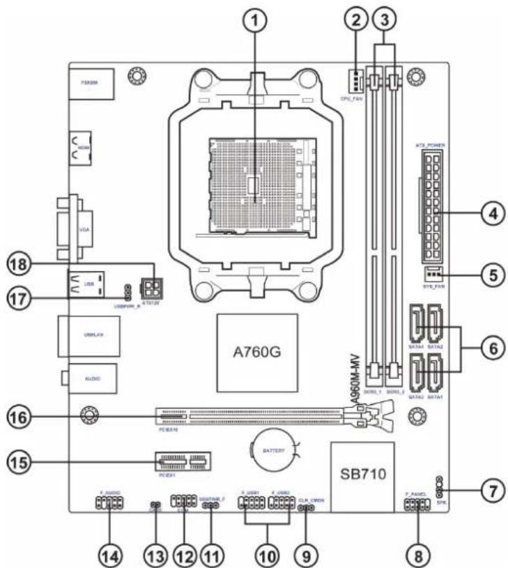
Table of Motherboard Components
| LABEL COMPONENTS | |
| 1. CPU Socket | supports socket AM3/AM3+ for AMD FX^TM /Phenom ^TM II/Athlon ^TM II/Sempron ^TM 100 series processors |
| 2. CPU_FAN CPU cooling fan connector | |
| 3. ATX_POWER Standard 24-pin ATX power connector | |
| 4. DDR3_1~2 240-pin DDR3 SDRAM slots | |
| 5. SYS_FAN System cooling fan connector | |
| 6. SATA1~4 Serial ATA 3Gb/s connectors | |
| 7. SPK Speaker header | |
| 8. F_PANEL Front panel switch/LED header | |
| 9. CLR_CMOS Clear CMOS jumper | |
| 10. F_USB1~2 Front panel USB 2.0 headers | |
| 11. USBPWR_F Front panel USB power select jumper | |
| 12. COM Serial port header | |
| 13. CASE Case open header | |
| 14. F_AUDIO Front panel audio header | |
| 15. PCIEX1 PCI Express x1 slots | |
| 16. PCIEX16 | PCI Express slot for graphics interface |
| 17. USBPWR_R | Rear USB/PS2 power select jumper |
| 18. ATX12V 4-pin +12V power connector | |

Chapter I
I/O Ports

- PS/2 Mouse (green)
Use the upper PS/2 port to connect a PS/2 mouse.
- PS/2 Keyboard (purple)
Use the lower PS/2 port to connect a PS/2 keyboard.
- HDMI Port (Optional)
You can connect the display device to the HDMI port.
- VGA Port
Connect your monitor to the VGA port.
- USB 2.0 Ports
Use the USB 2.0 ports to connect USB 2.0 devices.
- LAN Port
Connect an RJ-45 cable to the LAN port to connect your computer to the Network.
| LAN LED Status | Description | |
| Activity LED | OFF No data | |
| Orange blinking Active | ||
| Link LED | OFF No link | |
| Green Link | ||

- Line-in (blue)
It can be connected to an external CD/DVD player, Tape player or other audio devices for audio input.
- Line-out (lime)
It is used to connect to speakers or headphones.
- Microphone (pink)
It is used to connect to a microphone.
Chapter 2
Using BIOS
About the Setup Utility
The computer uses the latest "American Megatrends Inc." BIOS with support for Windows Plug and Play. The CMOS chip on the motherboard contains the ROM setup instructions for configuring the motherboard BIOS.
The BIOS (Basic Input and Output System) Setup Utility displays the system's configuration status and provides you with options to set system parameters. The parameters are stored in battery-backed-up CMOS RAM that saves this information when the power is turned off. When the system is turned back on, the system is configured with the values you stored in CMOS.
The BIOS Setup Utility enables you to configure:
• Hard drives, diskette drives and peripherals
• Video display type and display options
- Password protection from unauthorized use
• Power Management features
The settings made in the Setup Utility affect how the computer performs. Before using the Setup Utility, ensure that you understand the Setup Utility options.
This chapter provides explanations for Setup Utility options.
The Standard Configuration
A standard configuration has already been set in the Setup Utility. However, we recommend that you read this chapter in case you need to make any changes in the future.
This Setup Utility should be used:
- when changing the system configuration
- when a configuration error is detected and you are prompted to make changes to the Setup Utility
- when trying to resolve IRQ conflicts
- when making changes to the Power Management configuration
- when changing the password or making other changes to the Security Setup
Entering the Setup Utility
When you power on the system, BIOS enters the Power-On Self Test (POST) routines. POST is a series of built-in diagnostics performed by the BIOS. After the POST routines are completed, the following message appears:
Press DEL to enter SETUP
Press the delete key to access BIOS Setup Utility.
![Aptio Setup Utility - Copyright (C) 2011 American Megatrends, Inc. Main Advanced Chipset M.I.B. III Boot Security Exit BIOS Information System Date [Wed 09/19/2012] System Time [00:28:09] Set the Date. Use Tab to switch between Data elements. → ← :Select Screen ↑↓ :Select Item Enter : Select +/- : Change Opt. F1:General Help F2:Previous Values F3:Optimized Defaults F4:Save & Exit ESC:Exit Version 2.14.1219. Copyright (C) 2011 American Megatrends, Inc.](/content/2026/05/930387/images/6d72de8f7c3f9d39eb4cf84794e784782e0d858f0b19727777169db040654159.jpg)
Resetting the Default CMOS Values
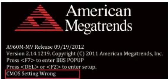
When powering on for the first time, the POST screen may show a "CMOS Settings Wrong" message. This standard message will appear following a clear CMOS data at factory by the manufacturer. You simply need to Load Default Settings to reset the default CMOS values.
Note: Changes to system hardware such as different CPU, memories, etc. may also trigger this message.
Using BIOS
When you start the Setup Utility, the main menu appears. The main menu of the Setup Utility displays a list of the options that are available. A highlight indicates which option is currently selected. Use the cursor arrow keys to move the highlight to other options. When an option is highlighted, execute the option by pressing
Some options lead to pop-up dialog boxes that prompt you to verify that you wish to execute that option. Other options lead to dialog boxes that prompt you for information.
Some options (marked with a triangle ▶) lead to submenus that enable you to change the values for the option. Use the cursor arrow keys to scroll through the items in the submenu.
In this manual, default values are enclosed in parenthesis. Submenu items are denoted by a triangle ▶.

The default BIOS setting for this motherboard apply for most conditions with optimum performance. We do not suggest users change the default values in the BIOS setup and take no responsibility to any damage caused by changing the BIOS settings.
BIOS Navigation Keys
The BIOS navigation keys are listed below:
| KEY FUNCTION | |
| ESC | Exits the current menu |
| ↑↓→← | Scrolls through the items on a menu |
| +/- Modifies the selected field's values | |
| Enter | Select |
| F1 General Help | |
| F2 Previous Value | |
| F3 Optimized Defaults | |
| F4 Save & Exit | |

For the purpose of better product maintenance, the manufacture reserves the right to change the BIOS items presented in this manual. The BIOS setup screens shown in this chapter are for reference only and may differ from the actual BIOS. Please visit the manufacture's website for updated manual.
Main Menu
When you enter the BIOS Setup program, the main menu appears, giving you an overview of the basic system information. Select an item and press
| BIOS InformationSystem Data [Wed 09/19/2012]System Time [00:28:09] | Set the Date. Use Tab to switch between Data elements. |
| → ← :Select Screen↑↓ :Select ItemEnter : Select+/- : Change Opt.F1:General HelpF2:Previous ValuesF3:Optimized DefaultsF4:Save & ExitESC:Exit |
System Date & Time
The system Date and Time items show the current date and time on the computer. If you are running a Windows OS, these items are automatically updated whenever you make changes to the Windows Date and Time Properties utility.
Advanced Menu
The Advanced menu items allow you to change the settings for the CPU and other system.
| Aptio Setup Utility - Copyright (C) 2011 American Megatrends, Inc. | |
| Main Advanced Chipset M.I.B. III Boot Security Exit | |
| Legacy OpROM SupportLaunch PXE OpROM [Disabled]Launch Storage OpROM [Enabled] | Enable or Disable Boot Optionfor Legacy Network Devices. |
| LAN ConfigurationPC Health StatusPower Management SetupACPI SettingsCPU ConfigurationSATA ConfigurationUSB ConfigurationSuper IO Configuration | — — :Select Screen↑↓ :Select ItemEnter: Select+/- : Change Opt.F1:General HelpF2:Previous ValuesF3:Optimized DefaultsF4:Save & ExitESC:Exit |
| Version 2.14.1219. Copyright (C) 2011 American Megatrends, Inc. | |
Launch PXE OpROM (Disabled)
Use this item to enable or disable the PXE OpROM.
Launch Storage OpROM (Enabled)
Use this item to enable or disable the Storage OpROM.
▶ LAN Configuration
The item in the menu shows the LAN-related information that the BIOS automatically detects.
| Main Advanced Chipset M.I.B. III Boot Security Exit | |
| LAN ConfigurationOnboard LAN Controller [Enabled] | |
| → ←:Select Screen↑↓ :Select ItemEnter : Select+/- : Change Opt.F1:General HelpF2:Previous ValuesF3:Optimized DefaultsF4:Save & ExitESC:Exit | |
| Version 2.14.1219. Copyright (C) 2011 American Megatrends, Inc. | |

Onboard LAN Controller (Enabled)
Use this item to enable or disable the Onboard LAN.
Press
▶ PC Health Status
On motherboards support hardware monitoring, this item lets you monitor the paemeters for critical voltages, temperatures and fan speeds.

▶Smart Fan Function
Scroll to this item and press
| Aptlo Setup Utility - Copyright (C) 2011 American Megatrends, Inc. | |
| Main Advanced Chipset M.I.B. III Boot Security Exit | |
| CPU Smart Fan Control [Enabled] Smart Fan Mode [Normal] High Limit Temperature(-C) 60 Low Limit Temperature(-C) 37 High Limit PWM 200 Low Limit PWM 56 | → — :Select Screen 1↓ :Select Item Enter : Select +/- : Change Opt. F1:General Help F2:Previous Values F3:Optimized Defaults F4:Save & Exit ESC:Exit |
| Version 2.14.1219. Copyright (C) 2011 American Megatrends, Inc. | |
CPU Smart Fan Control (Enabled)
This item allows you to enable/disable the control of the CPU fan speed by changing the fan voltage.
SMART Fan Mode (Normal)
This item allows you to select the fan mode (Normal, Quiet, Silent, or Manual) for a better operation environment. If you choose Normal mode, the fan speed will be auto adjusted depending on the CPU temperature. If you choose Quiet mode, the fan speed will be auto minimized for quiet environment. If you choose Silent mode, the fan speed will be auto restricted to make system more quietly. If you choose Manual mode, the fan speed will be adjust depending on users' parameters.
Press
System Component Characteristics
These items display the monitoring of the overall inboard hardware health events, such as System & CPU temperature, CPU & DIMM voltage, CPU & system fan speed,... etc.
- CPU Tct1
- CPU Fan Speed
- CPU Voltage
- DIMM Voltage
Press
▶ Power Management Setup
This page sets up some parameters for system power management operation.
| Aptio Setup Utility - Copyright (C) 2011 American Megatrends, Inc. | |
| Power Management SetupResume By RING [Disabled].Resume By PME [Disabled].Resume By USB 1.x/2.0 (S3) [Disabled].Resume By PS2 KB (S3) [Disabled].Resume By PS2 MS (S3) [Disabled].EUP Function [Enabled].Power LED Type [Dual Color LED] | About Resume by USB Ring |
| → ← :Select Screen↑↓ :Select ItemEnter : Select+/- : Change Opt.F1:General HelpF2:Previous ValuesF3:Optimized DefaultsF4:Save & ExitESC:Exit | |
| Version 2.14.1219. Copyright (C) 2011 American Megatrends, Inc. | |
Resume By RING (Disabled)
The system can be turned off with a software command. If you enable this item, the system can automatically resume if there is an incoming call on the Modem. You must use an ATX power supply in order to use this feature.
Resume By PME (Disabled)
This item is about resume by PCI/PCI-E/LAN/Ext.USB3.0 PME.
Resume By USB 1.x/2.0 (S3) (Disabled)
This item allows you to enable/disable the USB device wakeup function from S3 mode.
Resume By PS2 KB (S3) (Disabled)
This item enables or disables you to allow keyboard activity to awaken the system from power saving mode.
Resume By PS2 MS (S3) (Disabled)
This item enables or disables you to allow mouse activity to awaken the system from power saving mode.
EUP Support (Enabled)
This item allows user to enable or disable EUP support.
Power LED Type (Dual Color LED)
This item shows the type of the power LED.
Press
▶ACPI Setting
The item in the menu shows the highest ACPI sleep state when the system enters suspend.
| Main Advanced Chipset M.I.B. III Boot Security Exit | |
| ACPI SettingsACPI Sleep State [S3 (Suspend to RAM)] | Select the highest ACPI sleep state the system will enter when the Suspend button is pressed. |
| → :Select Screen↑↓ :Select ItemEnter: Select+/- :Change Opt.F1:General HelpF2:Previous ValuesF3:Optimized DefaultsF4:Save & ExitESC:Exit | |
ACPI Sleep State (S3(Suspend to RAM))
This item allows user to enter the ACPI S3 (Suspend to RAM) Sleep State (default).
Press
▶CPU Configuration
Scroll to this item and press
| Aptlo Setup Utility - Copyright (C) 2011 American Megatrends, Inc. | |||||
| Main | Advanced | Chipset | M.I.B. III | Boot | Security Exit |
| CPU ConfigurationSocket0: AMD FX(tm)-6100 Six-Core ProcessorMax Speed: 3300 MHz Intended Speed:3300 MHzMicrocode Patch Level: 6000624-- Information de cachette par noyau --L1 Instruction Cache: 64 KB/2-wayL1 Data Cache: 16 KB/4 wayL2 Cache: 2048 KB/16-wayTotal L3 Cache per Socket: 8 MB/64-wayAMD C&Q [Enabled]Core Performance Boost [Enabled]Core C6 State [Enabled]Enhanced Halt (CIE) [Disabled]SB Clock Spread Spectrum [Disabled] | |||||
| Version 2.14.1219. Copyright (C) 2011 American Megatrends, Inc. | |||||
Socket0: AMD FX(tm)-6100 Six-Core Processor
This is display-only field and displays the information of the CPU installed in your computer.
Max/Intended Speed (3300 MHZ)
These items show the maximum/intended speed of the CPU.
Microcode Patch Level (6000624)
This item shows the Microcode revision.
L1 Instruction Cache (64 KB/2-way)
This item shows CPU L1 Cache.
L1 Data Cache (16 KB/4-way)
This item shows CPU L1 Cache.
L2 Cache (2048 KB/16-way)
This item shows CPU L2 Cache.
Total L3 Cache per Socket (8 MB/64-way)
This item shows CPU L3 Cache.
AMD C&Q (Enabled)
This item enables or disables the CPU C&Q Function.
Core Performance Boost (Enabled)
This item enables or disables the Core performance boost.
Core C6 State (Enabled)
This item enables or disables the Core C6 state.
Enhanced Halt (CIE) (Disabled)
Use this item to enable the CPU energy-saving function when the system is not running.
SB Clock Spread Spectrum (Disabled)
This item enables or disables the SB Clock Spread Spectrum.
Press
▶SATA Configuration
Use this item to show the mode of serial SATA configuration options.
| Aptio Setup Utility - Copyright (C) 2011 American Megatrends, Inc. | |
| Main Advanced Chipset M.I.B. III Boot Security Exit | |
| SATA ConfigurationSerial-ATA Controller [Enhanced]SATA Mode [IDE Mode]SATA Port1 Not PresentSATA Port2 Not PresentSATA Port3 Not PresentSATA Port4 Not Present | Serial-ATA Controller |
| → ←:Select Screen↑↓ :Select ItemEnter : Select+/- : Change Opt.F1:General HelpF2:Previous ValuesF3:Optimized DefaultsF4:Save & ExitESC:Exit | |
| Version 2.14.1219. Copyright (C) 2011 American Megatrends, Inc. | |
Serial-ATA Controller (Enhanced)
Use this item to select Serial-ATA controller options: Disabled, Compatible, Enhanced.
SATA Mode (IDE Mode)
Use this item to select SATA mode.
SATA Port 1\~4 (Not Present)
This motherboard supports four SATA channel and each channel allows one SATA device to be installed. Use these items to configure each device on the SATA channel.
Press
▶USB Configuration
Scroll to this item and press
| Aptio Setup Utility - Copyright (C) 2011 American Megatrends, Inc. | ||||||
| Main | Advanced | Chipset | M.I.B. III | Boot | Security | Exit |
| USB ConfigurationAll USB Devices [Enabled]Legacy USB Support [Enabled] | ||||||
| → ←:Select Screen1↓ :Select ItemEnter : Select+/- : Change Opt.F1:General HelpF2:Previous ValuesF3:Optimized DefaultsF4:Save & ExitESC:Exit | ||||||
| Version 2.14.1219: Copyright (C) 2011 American Megatrends, Inc. | ||||||
All USB Devices (Enabled)
Use this item to enable or disable all USB devices.
Legacy USB Support (Enabled)
Use this item to enable or disable support for legacy USB devices. Setting to Audio allows the system to detect the presence of the USB device at startup. If detected, the USB controller legacy mode is enabled. If no USB device is detected, the legacy USB support is disabled.
Press
▶Super IO Configuration
Use this item to show the information of the Super IO Configuration.
| Aptio Setup Utility - Copyright (C) 2011 American Megatrends, Inc. | |
| Main Advanced Chipset M.I.B. III Boot Security Exit | |
| Super IO ConfigurationSuper IO Chip F71808A▶ Serial Port 0 Configutation | Set Parameters of Serial Port 0 (COMA) |
| • • :Select Screen1↓ :Select ItemEnter : Select+/- : Change Opt.F1:General HelpF2:Previous ValuesF3:Optimized DefaultsF4:Save & ExitESC:Exit | |
| Version 2.14.1219. Copyright (C) 2011 American Megatrends, Inc. | |
Super IO Chip (F71808A)
This item shows the information of the super IO chip.
▶ Serial Port 0 Configuration
Scroll to this item and press
| Aptio Setup Utility - Copyright (C) 2011 American Megatrends, Inc. | ||||||
| Main | Advanced | Chipset | M.I.B. III | Boot | Security | Exit |
| Serial Port 0 ConfigurationSerial Port [Enabled]Device Settings Reset RequiredChange Settings [Auto] | Enable or Disable Serial Port (COM) | |||||
| → ← :Select Screen1↓ :Select ItemEnter : Select+/- : Change Opt.F1:General HelpF2:Previous ValuesF3:Optimized DefaultsF4:Save & ExitESC:Exit | ||||||
| Version 2.14.1219. Copyright (C) 2011 American Megatrends, Inc. | ||||||
Serial Port (Enabled)
This item allows you to enable or disable serial port.
Device Settings (Reset Required)
This item shows the information of the device settings.
Change Settings (Auto)
Use this item to change device settings.
Press
Press
Chipset Menu
The chipset menu items allow you to change the settings for the North Bridge chipset, South Bridge chipset and other system.

▶ North Bridge
Scroll to this item and press
| Aptio Setup Utility - Copyright (C) 2011 American Megatrends, Inc. | |
| Main Advanced Chipset M.I.B. III Boot Security Exit | |
| North Chipset Configuration | |
| IGD Memory [Manual] UMA Frame Buffer Size [Auto] | |
| → ← :Select Screen 11 :Select Item Enter : Select +/- : Change Opt. F1:General Help F2:Previous Values F3:Optimized Defaults F4:Save & Exit ESC:Exit | |
| Version 2.14.1219. Copyright (C) 2011 American Megatrends, Inc. | |
IGD Memory (Manual)
This item shows the information of the IGD (Internal Graphics Device) memory.
UMA Frame Buffer Size (Auto)
Use this Item to adjust the share memory size of onboard VGA. This item only shows when IGD Memory set to manual.
Press
▶ South Bridge
Scroll to this item and press
| Aptio Setup Utility - Copyright (C) 2011 American Megatrends, Inc. | |
| Main Advanced Chipset M.I.B. III Boot Security Exit | |
| South BridgeRestore AC Power Loss [Power Ctf]Audio ConfigurationAzalia Internal HDMI codec [Enabled]Azalia HD Audio [Enabled]Case Open Warning [Disabled]Chassis Opened [No] | Specify what state to go to when power is re-applied after a power failure (G3 state).→←:Select Screen↑↓:Select ItemEnter: Select+/-: Change Opt.F1:General HelpF2:Previous ValuesF3:Optimized DefaultsF4:Save & ExitESC:Exit |
| Version 2.14.1219. Copyright (C) 2011 American Megatrends, Inc. | |

Restore AC Power Loss (Power Off)
This item enables your computer to automatically restart or return to its operating status.
Audio Configuration
This item shows the information of the audio configuration.
Azalia Internal HDMI codec (Enabled)
This item enables or disables Azaia Internal HDMI codec.
Azalia HD Audio (Enabled)
This item enables or disables Azalia HD audio.
Case Open Warning (Disabled)
This item enables or disables the warning if the case is opened up, and the item below indicates the current status of the case.
Chassis Opened (No)
This item indicates whether the case has been opened.
Press
M.I.B. III (MB Intelligent BIOS III) Menu
This page enables you to set the clock speed and system bus for your system. The clock speed and system bus are determined by the kind of processor you have installed in your system.

| Aptio Setup Utility - Copyright (C) 2011 American Megatrends, Inc. | |
| Main Advanced Chipset M.I.B. III Boot Security Exit | |
| M.I.B. III (MB Intelligent BIOS III)▶ Processor Power Planes and Voltage Controls▶ Memory Control▶ HT controlAuto Detect DIMM/PCI Clk [Enabled]Clockgen Spread Spectrum [Enabled]CPU/HT Reference Clock (MHz) 200VDIMM Voltage [1.6 V] | Processor Power Planes and Voltage Controls |
| → :Select Screen↑↓:Select ItemEnter: Select+/-: Change Opt.F1:General HelpF2:Previous ValuesF3:Optimized DefaultsF4:Save & ExitESC:Exit | |
| Version 2.14.1219. Copyright (C) 2011 American Megatrends, Inc. | |
▶ Processor Power Planes Voltage Controls
Scroll to this item to view the following screen:
| Aptio Setup Utility - Copyright (C) 2011 American Megatrends, Inc. | |
| Main Advanced Chipset M.I.B. III Boot Security Exit | |
| Processor Power Planes and Voltage ControlsCurrent CPU Speed 3300MHzCore clock multiplier [Auto]AltVidC3 Enable [Auto]Slam Time Mode [Auto]VSSlamTime [Auto] | Core clock multiplier |
| → :Select Screen↑↓:Select ItemEnter : Select+/- : Change Opt.F1:General HelpF2:Previous ValuesF3:Optimized DefaultsF4:Save & ExitESC:Exit | |
| Version 2.14.1219. Copyright (C) 2011 American Megatrends, Inc. | |
Current CPU Speed (3300MHz)
This item shows current CPU speed.
Core Clock multiplier (Auto)
Use this item to set the core clock multiplier.
AltVidC3 Enable (Auto)
This item allows you to select amdAltVidEn 0:24N:3x80[12].
Slam Time Mode (Auto)
This item enables you to set slam time mode, this option is only for RB-C3, BL-C3, DA-C3.
VSSlamTime (Auto)
This item specifies the time to wait for voltage stabilization during altvid transitions if a new VID is provided to the voltage regulator without ramping. 0:24N:3xDC [31:29].
Press
▶ Memory Control
Scroll to this item to view the following screen:
| Aptio Setup Utility - Copyright (C) 2011 American Megatrends, Inc. | |
| Main Advanced Chipset M.I.B. III Boot Security Exit | |
| Memory ControlMemory Clock DCT0 is: NoneMemory Clock DCT1 is: (DDR-1333/667Mhz)Command Rate [Auto]Memory Clock Mode [Manual]Memclock Value [333MHz]Memory Timing Mode [Auto]CAS Latency 9RAS to CAS Delay 9Row Precharge Time 9RAS Active Time 24Row Cycle Time 33RAS to RAS Delay 4Read CAS to Precharge Time 5 | Set Memory Clock Mode.→ — :Select Screen11 :Select ItemEnter : Select+/- : ValueF1:General HelpF2:Previous ValueF3:Optimized DefaultsF4:Save & ExitESC:Exit |
| Version 2.14.1219. Copyright (C) 2011 American Megatrends, Inc. | |
Memory Clock DCT0/1 is (None/DDR3-1333/667 Mhz)
This item shows the current memory clock of DCT0/1.
Command Rate (Auto)
This item allows you to set command rate.
Memory Clock Mode (Manual)
This item allows you to set memory clock mode. Default is Auto.
Memclock Value (333MHz)
This item allows you to set memclock value. This item only shows when Memory Clock Mode set to Manual or Limited.
Memory Timing Mode (Auto)
This item allows you to select memory timing mode.
CAS Latency (9)
This item determines the operation of DDR SDRAM memory CAS (column address strobe). It is recommended that you leave this item at the default value. The 2T setting requires faster memory that specifically supports this mode.
RAS to CAS Delay (9)
This item specifies RAS# to CAS# delay to Rd/Wr command to the same bank.
Row Precharge Time (9)
This item specifies Row precharge to Active or Auto-Refresh of the same bank.
RAS Active Time (24)
This item specifies the RAS# active time.
Row Cycle Time (33)
This item specifies the Row cycle time.
RAS to RAS Delay (4)
This item specifies RAS# to RAS# delay to Rd/Wr command to the same bank.
Read CAS to Precharge Time (5)
This item controls the Read to precharge delay for memory devices, in memory clock cycles.
Press
▶HT Control
Scroll to this item to view the following screen:
| Aptio Setup Utility - Copyright (C) 2011 American Megatrends, Inc. | |
| Main Advanced Chipset M.I.B. III Boot Security Exit | |
| HT controlCurrent Width Up: 16 bitUpstream Link Width [Auto]Current Width Down: 16 bitDownstream Link Width: [Auto]Current IO HT Freq: 2200MhzIO HT Frequency [Auto] | Set Upstream Link Width |
| → ← :Select Screen1↓ :Select ItemEnter : Select+/- : ValueF1:General HelpF2:Previous ValueF3:Optimized DefaultsF4:Save & ExitESC:Exit | |
Current Width Up (16 bit)
This item shows the current Upstream Link Width.
Upstream Link Width (Auto)
This item allows you to set Upstream Link Width.
Current Width Down (16 bit)
This item shows the current Downstream Link Width.
Downstream Link Width (Auto)
This item allows you to set Downstream Link Width.
Current IO HT Freq (2200Mhz)
This item shows the current IO HT Frequency.
IO HT Frequency (Auto)
This item allows you to set IO HT Frequency.
Boot Menu
This page enables you to set the keyboard NumLock state.
| Aptlo Setup Utility - Copyright (C) 2011 American Megatrends, Inc.Main Advanced Chipset M.I.B. III Boot Security Exit | |
| Boot ConfigurationBootup NumLock State [On]Set Boot Priority1st Boot [Hard Disk]2nd Boot [CD/DVD]3rd Boot [USB/Floppy]4th Boot [USB CD/DVD]5th Boot [USB Hard Disk]6th Boot [USB Key: USB]7th Boot [Network]8th Boot [UEFI]►Hard Disk Drive BBS Priorities [Press Enter]►CD/DVD ROM Drive BBS Priorities [Press Enter]►USB Floppy/Floppy Drive BBS Priorities [Press Enter]►USB CD/DVD Drive BBS Priorities [Press Enter]►USB Hardisk Drive BBS Priorities [Press Enter]►USB Key Drive BBS Priorities [Press Enter]►Network Drive BBS Priorities [Press Enter]►UEFI Boot Drive BBS Priorities [Press Enter] | Select the keyboard NumLock state→ ← :Select Screen1↓ :Select ItemEnter : Select+/- : Change Opt.F1:General HelpF2:Previous ValuesF3:Optimized DefaultsF4:Save & ExitESC:Exit |
| Version 2.14.1219. Copyright (C) 2011 American Megatrends, Inc. | |
Boot Configuration
This item shows the information of the boot configuration.
Bootup NumLock State (On)
This item determines if the NumLock key is active or inactive at system start-up time.
1st/2nd/3rd/4th/5th/6th/7th/8th Boot
These items set the system boot order.
Hard Disk Drive BBS Priorities (Press Enter)
This Item enables you to specify the sequence of loading the operating system from the installing hard disk drives.
CD/DVD ROM Drive BBS Priorities (Press Enter)
This item enables you to specify the sequence of loading the operating system from the installing CD/DVD ROM drives.
USB Floppy/Floppy Drive BBS Priorities (Press Enter)
This Item enables you to specify the sequence of loading the operating system from the installing USB/floppy drives.
USB CD/DVD ROM Drive BBS Priorities (Press Enter)
This item enables you to specify the sequence of loading the operating system from the installing USB CD/DVD ROM drives.
USB Hardisk Drive BBS Priorities (Press Enter)
This item enables you to specify the sequence of loading the operating system from the installing USB harddisk drives.
USB Key Drive BBS Priorities (Press Enter)
This item enables you to specify the sequence of loading the operating system from the installing USB flash drives.
Network Device BBS Priorities (Press Enter)
This item enables you to specify the sequence of loading the operating system from the installing network devices.
UEFI Boot Drive BBS Priorities (Press Enter)
This item enables you to specify the sequence of loading the operating system from the installing UEFI Boot drives.
Security Menu
This page enables you to set setup administrator and password.
| Aptio Setup Utility - Copyright (C) 2011 American Megatrends, Inc. | |
| Main Advanced Chipset M.I.B. III Boot Security Exit | |
| Administrator Password Status Not InstallUser Password Status Not InstallAdministrator Password | Set Setup AdministratorPassword |
| → ← :Select Screen↓ :Select ItemEnter : Select+/- : Change Opt.F1:General HelpF2:Previous ValuesF3:Optimized DefaultsF4:Save & ExitESC:Exit | |
| Version 2.14.1219. Copyright (C) 2011 American Megatrends, Inc. | |

Administrator Password Status (Not Install)
This item shows administrator password installed or not.
User Password Status (Not Install)
This item shows user password installed or not.
Administrator Password
Press
Exit Menu
This page enables you to exit system setup after saving or without saving the changes.
| Aptlo Setup Utility - Copyright (C) 2011 American Megatrends, Inc. | |
| Main Advanced Chipset M.I.B. III Boot Security Exit | |
| Save Changes and ExitDiscard Changes and ExitSave Changes and ResetDiscard Changes and ResetSave OptionsSave ChangesDiscard ChangesRestore DefaultsSave as User DefaultsRestore User DefaultsBoot OverrideUSB | Exit system setup after saving the changes.→ ← :Select Screen↑↓ :Select ItemEnter : Select+/- : Change Opt.F1:General HelpF2:Previous ValuesF3:Optimized DefaultsF4:Save & ExitESC:Exit |
| Version 2.14.1219. Copyright (C) 2011 American Megatrends, Inc. | |
Save Changes and Exit
This item enables you to save the changes that you have made and exit.
Discard Changes and Exit
This item enables you to discard any changes that you have made and exit.
Save Changes and Reset
This item enables you to save the changes that you have made and reset.
Discard Changes and Reset
This item enables you to discard any changes that you have made and reset.
Save Options
This item enables you to save the options that you have made.
Save Changes
This item enables you to save the changes that you have made.
Discard Changes
This item enables you to discard any changes that you have made.
Restore Defaults
This item enables you to restore the system defaults.
Save as User Defaults
This item enables you to save the changes that you have made as user defaults.
This item enables you to restore user defaults.
Boot Override
Use this item to select the boot device.
Updating the BIOS
You can download and install updated BIOS for this motherboard from the manufacturer's Web site. New BIOS provides support for new peripherals, improvements in performance, or fixes for known bugs. Install new BIOS as follows:
1 If your motherboard has a BIOS protection jumper, change the setting to allow BIOS flashing.
2 If your motherboard has an item called Firmware Write Protect in Advanced BIOS features, disable it. (Firmware Write Protect prevents BIOS from being overwritten.)
3 Prepare a bootable device or create a bootable system disk. (Refer to Windows online help for information on creating a bootable system disk.)
4 Download the Flash Utility and new BIOS file from the manufacturer's Web site. Copy these files to the bootable device.
5 Turn off your computer and insert the bootable device in your computer. (You might need to run the Setup Utility and change the boot priority items on the Advanced BIOS Features Setup page, to force your computer to boot from the bootable device first.)
6 At the C:\ or A:\ prompt, type the Flash Utility program name and the file name of the new BIOS and then press
7 When the installation is complete, remove the bootable device from the computer and restart your computer. If your motherboard has a Flash BIOS jumper, reset the jumper to protect the newly installed BIOS from being overwritten. The computer will restart automatically.
This concludes Chapter 3. Refer to the next chapter for information on the software supplied with the motherboard.
Memo
Chapter 2
Chapter 3
Using the Motherboard Software
Auto-installing under Windows XP/7/8
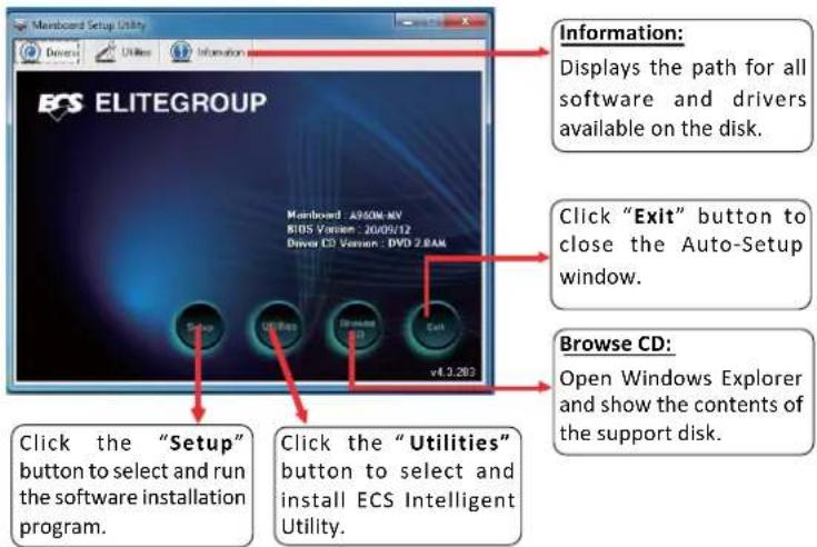
The auto-install DVD-ROM makes it easy for you to install the drivers and software. The support software DVD-ROM disc loads automatically under Windows XP/7/8. When you insert the DVD-ROM disc in the DVD-ROM drive, the auto-run feature will automatically bring up the installation screen. The screen has four buttons on it: Setup, Utilities, Browse CD and Exit.

Running Setup
Follow these instructions to install device drivers and software for the motherboard:
- Click Setup. The installation program begins:


The following screens are examples only. The screens and driver lists will be different according to the motherboard you are installing.
The motherboard identification is located in the upper left-hand corner.
+×★☆☆☆☆☆☆☆
- Click Next. The following screen appears:

-
Check the box next to the items you want to install. The default options are recommended.
-
Click Next to run the Installation Wizard. An Item Installation screen appears:

- Follow the instructions on the screen to install the items.
Drivers and software are automatically installed in sequence. Follow the onscreen instructions, confirm commands and allow the computer to restart a few times to complete the installation.
Windows 8 will show the following screen after system restart, you must select "Desktop" in the bottom left to install the next driver.

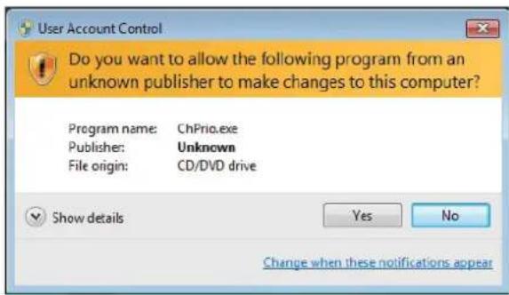
Windows 7/8 will appear below UAC (User Account Control) message after the system restart. You must select "Yes" to install the next driver. Continue this process to complete the drivers installation.

Manual Installation
If the auto-install DVD-ROM does not work on your system, you can still install drivers through the file manager for your OS (for example, Windows Explorer). Look for the chipset and motherboard model, and then browse to the directory and path to begin installing the drivers. Most drivers have a setup program (SETUP.EXE) that automatically detects your operating system before installation. Other drivers have the setup program located in the operating system subfolder.
If the driver you want to install does not have a setup program, browse to the operating system subfolder and locate the readme text file (README.TXT or README.DOC) for information on installing the driver or software for your operating system.
ECS Utility Software (Intelligent EZ Utility)
ECS Intelligent EZ Utility provides friendly interfaces under Windows O.S, which makes your computing more easily and conveniently.

These software(s) are subject to change at anytime without prior notice. Please refer to the support disk for available software.
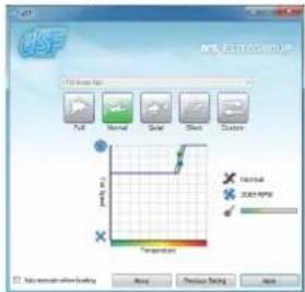
eSF
eSF(Smart Fan) utility provides easy and safe way to adjust fan speed in accordance with your PC's system loading and temperature.
It has five modes to adjust fan speed in a safe range without entering the BIOS to optimize your system cooling environment.
Chapter 3

Microsoft .NET Framework 3.5 is required.
eDLU
ECS eDLU utility makes updating drivers fast and easy. eDLU saves time and hassle by listing all the latest drivers online. Just select the one you prefer and start to download and install the drivers.

eBLU
ECS eBLU utility makes BIOS update faster and easier. eBLU will list the latest BIOS with a default check-mark. Click "install" button to install.


Microsoft .NET Framework 3.5 is required.
☆+×☆☆☆☆☆☆☆☆☆☆
eOC
ECS eOC Utility is a simple over-clocking tool that provides user-friendly windows operation interface for novices and over-clockers. Combining with ECS MIB III technology, eOC challenges the undiscovered over-clocking capability than ever before.
Monitor Easy Tuning

Advance Tuning


Options


Memo
Chapter 3
Chapter 4
Trouble Shooting
Start up problems during assembly
After assembling the PC for the first time you may experience some start up problems. Before calling for technical support or returning for warranty, this chapter may help to address some of the common questions using some basic troubleshooting tips. You may also log onto our ECS website for more information: http://www.ecs.com.tw/ECSWebSite/Support/Support_FAQ.aspx?MenuID=49&childid=M_49&LanID=0
a) System does not power up and the fans are not running.
- Disassemble the PC to remove the VGA adaptor card, DDR memory, LAN, USB and other peripherals including keyboard and mouse. Leave only the motherboard, CPU with CPU cooler and power supply connected. Make sure the power cord is plugged into the wall socket & the switch on the Power Supply Unit (PSU) is turned "on" as well. Turn on again to see if the CPU and power supply fans are running.
- Make sure to remove any unused screws or other metal objects such as screwdrivers from the inside PC case. This is to prevent damage from short circuit.
- Check the CPU FAN connector is connected to the motherboard.
- For Intel platforms check the pins on the CPU socket for damage or bent. A bent pin may cause failure to boot and sometimes permanent damage from short circuit.
- Check the 12V power connector is connected to the motherboard.
- Check that the 12V power & ATX connectors are fully inserted into the motherboard connectors. Make sure the latches of the cable and connector are locked into place.
b) Power is on, fans are running but there is no display
- Make sure the monitor is turned on and the monitor cable is properly connected to the PC.
- Check the VGA adapter card (if applicable) is inserted properly.
- Listen for beep sounds. If you are using internal PC speaker make sure it is connected.
a. continuous 3 short beeps: memory not detected
b. 1 long beep and 8 short beeps: VGA not detected
c) The PC suddenly shuts down while booting up.
-
The CPU may experience overheating so it will shutdown to protect itself. Apply the thermal grease onto the CPU heatsink & ensure the CPU fan is well-connected with the CPU heatsink. Check if the CPU fan is working properly while the system is running.
-
From the BIOS setting, try to disable the Smartfan function to let the fan run at default speed. Doing a Load Optimised Default will also disable the Smartfan.
Start up problems after prolong use
After a prolong period of use your PC may experience start up problems again. This may be caused by breakdown of devices connected to the motherboard such as HDD, CPU fan, etc. The following tips may help to revive the PC or identify the cause of failure.
- Clear the CMOS values using the CLR_CMOS jumper. Refer to CLR_CMOS jumper in Chapter 2 for Checking Jumper Settings in this user manual. When completed, follow up with a Load Optimised Default in the BIOS setup.
- Check the CPU cooler fan for dust. Long term accumulation of dust will reduce its effectiveness to cool the processor. Clean the cooler or replace a new one if necessary.
- Check that the 12V power & ATX connectors are fully inserted into the motherboard connectors. Make sure the latches of the cable and connector are locked into place.
- Remove the hard drive, optical drive or DDR memory to determine which of these components may be at fault.
- Check whether there is any bulked up electrolytic capacitor or abnormal component.
Please logo onto our ECS website: http://www.ecs.com.tw/ECSWebSite/Support/Technical_Support_List.aspx?MenuID=50&LanID=0 for more information.
Maintenance and care tips
Your computer, like any electrical appliance, requires proper care and maintenance. Here are some basic PC care tips to help prolong the life of the motherboard and keep it running as best as it can.
- Keep your computer in a well ventilated area. Leave some space between the PC and the wall for sufficient airflow.
- Keep your computer in a cool dry place. Avoid dusty areas, direct sunlight and areas of high moisture content.
- Routinely clean the CPU cooler fan to remove dust and hair.
- In places of hot and humid weather you should turn on your computer once every other week to circulate the air and prevent damage from humidity.
- Add more memory to your computer if possible. This not only speeds up the system but also reduces the loading of your hard drive to prolong its life span.
- If possible, ensure the power cord has an earth ground pin directly from the wall outlet. This will reduce voltage fluctuation that may damage sensitive devices.

flowchart
graph TD
    A["Start"] --> B{Unit}
    B -->|Yes| C{Check if monitor has display}
    B -->|No| D{d#uos peeb}
    D -->|Yes| E["CLR CMOS and restart.<br>AMF catnoc ,lief fl"]
    D -->|No| F["CP eht catseR"]
    F --> G{rotho# troh 8 dna peeb gnol}
    G -->|Yes| H["eu# received larehpireP<br>elborp BD<br>,rorrrouteASO<br>need to CLRCMOS."]
    G -->|No| I["cl#us peeb"]
    I --> J["kce# dna SOMC RLC<br>rewio V21 UPC fi<br>detcenne si"]
    J --> K["?draob ro USP htiw melborP<br>AM# tcatnoc >elborp draob II"]
    K --> L["hc#us USP no nruT<br>tscos llaw ot tcannoc ro<br>.tratser rna"]
    L --> M["CLR CMOS and restart"]
    N["Start"] --> O["User rewoP<br>.trats ot of CP tub"]
    O --> P{Unit}
    P -->|Yes| Q["Check if monitor has display"]
    P -->|No| R{d#uos peeb}
    R -->|Yes| S["Cl#ecs TSO"]
    R -->|No| T["CP eht catseR"]
    T --> U["rolto# troh 8 yalpsid san"]
    U --> V["elborp draoB<br>AM# tcatnoc >-"]
    V --> W["System fail to start or unstable<br>aft cet##QB yfloc"]
    W --> X["CLR CMOS and restart"]
Memo
Chapter 4
Hardware Installation Guide
Installation Steps
Step1. Installation of the CPU and CPU Cooler:
1-1. Position lever at a 90 degree angle.
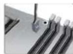
1-2. Locate the CPU cut edge (the corner with the pin hold noticeably missing). Align and insert the CPU correctly, then press the metal lever back into its original position.

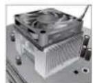
1-3. Apply thermal grease on top of the CPU. Put the CPU Fan down on the retention module and flip the levers over the heat sink in place.

1-4. Connect the CPU cooler power connector to the CPU_FAN connector.
Step2. Installation of Memory Modules:
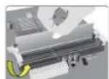
2-1. Unfasten the latches on each side of the DIMM slots.
2-2. Firmly press the DIMM down until it seats correctly. Make sure the slot latches are levered upwards and latch on the edge of the DIMM.

Step3. Installation of Motherboard:
3-1. Replace the back I/O plate of the case with the I/O shield provided in motherboard's package.
3-2. Place the motherboard within the case by positioning it into the I/O plate. Secure the motherboard to the case with screws.


Step4. Installation of storage devices:
4-1. Please remove the front cover and 5.25" plate from the case.
4-2. Place the storage devices (IDE/SATA/FDD) in its position within the case and secure the device with screws.


Step5. Case Preparation and Installation of Power Supply:
Remove both sides and the lid of the case, and then install the power supply with screws.

It is recommended to use a power supply delivering more than 300W of power. Insufficient power supply may cause unstable boot-up.

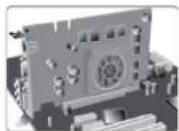
Step6. Installation of an Expansion card:
Remove the metal located on the slot and then insert the expansion card into the slot. Press the card firmly to make sure it is fully inserted into its slot. And then return the screw back to its position.
Step7. Connecting Cables and Power Connectors:
a. Connect the SATA hard drive to its SATA cable
b. Connect SATA power connector to the SATA device

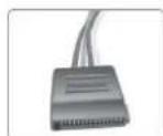
c. Connect 24-pin power cable
Please note that when installing 24-pin power cable, the latches of power cable and the ATX connector match perfectly.
d. Connect 4-pin power cable
The ATX_12V 4-Pin power connector is used to provide power to the CPU. When installing 4-pin power cable, the latch of power cable matches the ATX_12V connector perfectly.


Step 8: Connecting ports on the case:
Once the steps above have been completed, please connect the peripherals such as the keyboard, mouse, monitor, etc. Then, connect the power and turn on the system. Please install all the required software.
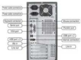
Please install all peripheral devices.
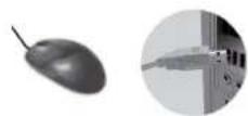
8-1. Keyboard connection

8-3. Monitor connection

8-5. Power connection
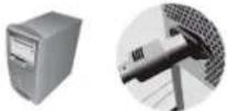
8-2. Printer connection

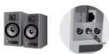
8-4. Speaker connection

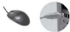
8-6. Mouse connection

To prevent component damage, do not power up the system until the installation is complete.
Using BIOS
The BIOS (Basic Input and Output System) Setup Utility displays the system's configuration status and provides you options to set system parameters. When you power on the system, BIOS enters the Power-On Self Test (POST) routines, please press or F2 to enter setup. When powering on for the first time, the POST screen may show a "CMOS Settings Wrong" message. Please enter BIOS and choose "Load Default Settings" to reset the default CMOS values. (Changes to system hardware such as different CPU, memories, etc. may also trigger this message.)
BIOS Navigation Keys
| KEY | FUNCTION |
| ESC | Exits the current menu |
| Scrolls through the items on a menu | |
| +/- | Modifies the selected field's values |
| Enter | Select |
| F1 | General Help |
| F2 | Previous Value |
| F3 | Optimized Defaults |
| F4 | Save & Exit |

The sequence of installation may differ depending on the type of case and devices used.
Por favor, instale todos os dispositivos periféricos.
8-1. Conexão de teclado

2-8 نوصيل الطابعة
安装所有外围设备:
8-1. 连接键盘

8-3. 连接显示器

8-5. 连接电源
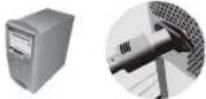
8-2. 连接打印机

8-4. 连接喇叭
8-6. 连接鼠标

모든 주변 기기를 설치합니다.
8-1.키보드연결
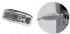
8-3. 모니터 연결
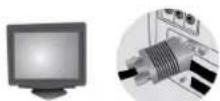
8-5. 전원 연결

8-2.프린터 연결

8-4.스피커 연결
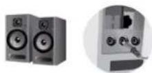
8-6.마우스 연결


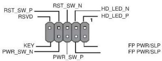
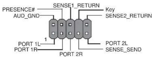
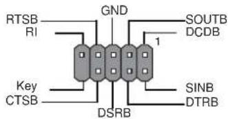
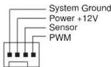
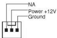
Header Pin Definition and Jumper Settings
F PANEL
F_AUDIO
COM
F USB1\~2

SPK

CPU_FAN
SYS_FAN
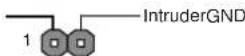
- CASE
- CLR_CMOS Jumper
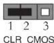
1-2: NORMAL 2-3: CLEAR CMOS
Before clearing the CMOS, make sure to turn off the system.
- USBPWR_R1(Rear USB PS/2 Power Select Jumper)


- USBPWR_F1(Front Panel USB Power Select Jumper)



- ✿✿✿✿✿○✿]
- \*□\*\*○\*\*]\*\*\*□■■□■
- ◆※※□●◆□○○◆■※※▼□■▲◆□○○▲▲□■◆◆
- ◆■□○○■□○○◆■□▲
- TABLE OF CONTENTS
- Chapter 1 1
- Introducing the Motherboard 1
- Chapter 2 7
- Using BIOS 7
- Chapter 3 33
- Using the Motherboard Software 33
- Chapter 4 39
- Trouble Shooting 39
- Multi-language Quick Installation Guide 43
- Appendix 77
- Chapter 1
- Introducing the Motherboard
- Introduction
- Package Contents
- Chapter 2
- Using BIOS
- About the Setup Utility
- The Standard Configuration
- Entering the Setup Utility
- Press DEL to enter SETUP
- Resetting the Default CMOS Values
- BIOS Navigation Keys
- Main Menu
- System Date & Time
- Advanced Menu
- Launch PXE OpROM (Disabled)
- Launch Storage OpROM (Enabled)
- ▶ LAN Configuration
- Onboard LAN Controller (Enabled)
- ▶ PC Health Status
- ▶Smart Fan Function
- CPU Smart Fan Control (Enabled)
- SMART Fan Mode (Normal)
- System Component Characteristics
- ▶ Power Management Setup
- Resume By RING (Disabled)
- Resume By PME (Disabled)
- Resume By USB 1.x/2.0 (S3) (Disabled)
- Resume By PS2 KB (S3) (Disabled)
- Resume By PS2 MS (S3) (Disabled)
- EUP Support (Enabled)
- Power LED Type (Dual Color LED)
- ▶ACPI Setting
- ACPI Sleep State (S3(Suspend to RAM))
- ▶CPU Configuration
- ▶SATA Configuration
- Serial-ATA Controller (Enhanced)
- SATA Mode (IDE Mode)
- SATA Port 1\~4 (Not Present)
- ▶USB Configuration
- All USB Devices (Enabled)
- Legacy USB Support (Enabled)
- ▶Super IO Configuration
- Super IO Chip (F71808A)
- ▶ Serial Port 0 Configuration
- Serial Port (Enabled)
- Device Settings (Reset Required)
- Change Settings (Auto)
- Chipset Menu
- ▶ North Bridge
- IGD Memory (Manual)
- UMA Frame Buffer Size (Auto)
- ▶ South Bridge
- Restore AC Power Loss (Power Off)
- Audio Configuration
- Azalia Internal HDMI codec (Enabled)
- Azalia HD Audio (Enabled)
- Case Open Warning (Disabled)
- Chassis Opened (No)
- M.I.B. III (MB Intelligent BIOS III) Menu
- ▶ Processor Power Planes Voltage Controls
- ▶ Memory Control
- Memory Clock DCT0/1 is (None/DDR3-1333/667 Mhz)
- Command Rate (Auto)
- Memory Clock Mode (Manual)
- Memclock Value (333MHz)
- Memory Timing Mode (Auto)
- CAS Latency (9)
- RAS to CAS Delay (9)
- Row Precharge Time (9)
- RAS Active Time (24)
- Row Cycle Time (33)
- RAS to RAS Delay (4)
- Read CAS to Precharge Time (5)
- ▶HT Control
- Current Width Up (16 bit)
- Upstream Link Width (Auto)
- Current Width Down (16 bit)
- Downstream Link Width (Auto)
- Current IO HT Freq (2200Mhz)
- IO HT Frequency (Auto)
- Boot Menu
- Boot Configuration
- Bootup NumLock State (On)
- 1st/2nd/3rd/4th/5th/6th/7th/8th Boot
- Hard Disk Drive BBS Priorities (Press Enter)
- CD/DVD ROM Drive BBS Priorities (Press Enter)
- USB Floppy/Floppy Drive BBS Priorities (Press Enter)
- USB CD/DVD ROM Drive BBS Priorities (Press Enter)
- USB Hardisk Drive BBS Priorities (Press Enter)
- USB Key Drive BBS Priorities (Press Enter)
- Network Device BBS Priorities (Press Enter)
- UEFI Boot Drive BBS Priorities (Press Enter)
- Security Menu
- Administrator Password Status (Not Install)
- User Password Status (Not Install)
- Administrator Password
- Exit Menu
- Save Changes and Exit
- Discard Changes and Exit
- Save Changes and Reset
- Discard Changes and Reset
- Save Options
- Save Changes
- Discard Changes
- Restore Defaults
- Save as User Defaults
- Boot Override
- Updating the BIOS
- Chapter 3
- Using the Motherboard Software
- Auto-installing under Windows XP/7/8
- Running Setup
- Manual Installation
- ECS Utility Software (Intelligent EZ Utility)
- eSF
- eDLU
- eBLU
- eOC
- Chapter 4
- Trouble Shooting
- Start up problems during assembly
- a) System does not power up and the fans are not running.
- b) Power is on, fans are running but there is no display
- c) The PC suddenly shuts down while booting up.
- Start up problems after prolong use
- Maintenance and care tips
- Hardware Installation Guide
- Installation Steps
- Step1. Installation of the CPU and CPU Cooler:
- Step2. Installation of Memory Modules:
- Step3. Installation of Motherboard:
- Step4. Installation of storage devices:
- Step5. Case Preparation and Installation of Power Supply:
- Step6. Installation of an Expansion card:
- Step7. Connecting Cables and Power Connectors:
- c. Connect 24-pin power cable
- d. Connect 4-pin power cable
- Step 8: Connecting ports on the case:
- Header Pin Definition and Jumper Settings
Brand : ECS
Model : A960M-MV
Category : Motherboard