Stealth ST4.1000D - Receiver Soundstream - Free user manual and instructions
Find the device manual for free Stealth ST4.1000D Soundstream in PDF.


| Product Type | Car Audio Amplifier |
| Number of Channels | 4 |
| RMS Power (4 ohms) | 100W x 4 |
| RMS Power (2 ohms) | 150W x 4 |
| Bridged RMS Power (4 ohms) | 300W x 2 |
| Max Power Rating | 1000W |
| Amplifier Class | Class D |
| Frequency Response | 10Hz - 30kHz |
| Signal-to-Noise Ratio | > 90dB |
| Input Sensitivity | 0.2V - 6V |
| Built-in Crossover | Variable Low-Pass / High-Pass / Full Range |
| Bass Boost | 0 - 12dB @ 45Hz |
| Dimensions (L x W x H) | 11.1 x 6.3 x 2.0 inches (282 x 160 x 51 mm) |
| Weight | 3.5 lbs (1.6 kg) |
| Power Supply | 10V - 16V DC |
| Fuse Rating | 60A (external fuse recommended) |
| Protection Circuits | Thermal, Short Circuit, Overload, DC Offset |
| Mounting Type | Horizontal or Vertical |
| Speaker Impedance | 2 - 8 ohms (stereo), 4 - 8 ohms (bridged) |
| Remote Turn-On | 12V trigger wire |
Frequently Asked Questions - Stealth ST4.1000D Soundstream
User questions about Stealth ST4.1000D Soundstream
0 question about this device. Answer the ones you know or ask your own.
Ask a new question about this device
Download the instructions for your Receiver in PDF format for free! Find your manual Stealth ST4.1000D - Soundstream and take your electronic device back in hand. On this page are published all the documents necessary for the use of your device. Stealth ST4.1000D by Soundstream.
USER MANUAL Stealth ST4.1000D Soundstream
Thank you for your decision to purchase a MICRO MINI mobile amplifier! Our Amplifiers are the result of extensive engineering, testing, and bullet proof construction. Their versatility enables compatibility with optional signal and audio processors. These high quality MOSFET amplifiers may be configured to allow maximum flexibility in designing different types of speaker systems.
DIGITAL CLASS D FULL RANGE AMPLIFIERS
The MICRO MINI Series are high quality MOSFET amplifiers that are capable of running a system full range, or they may be selected only to power subwoofers. It is important that you closely follow the wiring instructions contained in this Owners Manual so that you get the most from your MICRO MINI mobile amplifier.
CAUTION
High powered audio systems in a vehicle are capable of generating higher then "Live Concert" levels of sound pressure. Continued exposure to excessively high volume sound levels will cause hearing loss or damage. Also, operation of a motor vehicle while listening to audio equipment at high volume levels may impair your ability to hear external sounds such as horns, warning signals, or emergency vehicles - thus creating a potential traffic hazard.
In the interest of safety, MICRO MINI highly recommends listening at lower volume levels when driving.
TECHNICAL FEATURES
• Class-D Digital Full range 2ohm stable stereo.
• Low-power Consumption Circuit.
• Tri-mode capable.
• Full MOSFET DC-DC PWM Power Supply.
• Four way protection.
• Double sided FR-4 PC Board.
• SMD technology.
• High level input connector (Auto turn ON).
- Adjustable Low-pass, Hi-pass, Bass boost, Sub sonic filter.
- RCA input connectors (No Auto turn ON).
- Connector to connector Power/Speaker terminals.
- Ultra slim size.
INSTALLATION EXPERIENCE
Installation of MICRO MINI mobile amplifiers requires detailed knowledge of electronics wiring and proper speaker impedance.
We strongly recommend installation by an authorized our dealer.
This Owners Manual only provides general installation and operation instructions. If you have any reservations about your installation skills, please contact your local our dealer for assistance.

PREPARING FOR INSTALLATION
NOTE: The tools listed below may be required for basic installation
• An electric drill with bits
• Philips head and standard screwdrivers
- Wire strippers
- Crimping tool
• VOM (electronic volt ohm meter)
• Heat shrink tubing and gun
- Soldering iron

INSTALLATION PRECAUTIONS
NOTE: Proceed only if you are qualified installer otherwise, let your dealer do it. Always wear protective eyewear when using tools.
- Turn off all stereo and other electrical devices before you begin.
- Disconnect the negative (-) lead from your vehicles battery.
- Locate all fuel lines, brake lines, oil lines, and electrical cables when planning the install.
• Make sure there is at least 2-inches (5 cm) around the air vents on the amplifier. - When connecting ground points, make sure all paint is carefully scrapped away from the auto body and contact is make with bare metal.
- Use a utility knife to trim away fabric from hole locations before drilling or cutting.
- When running power cables through sheet metal, be sure to use grommets to properly insulate the metal edges from the wire insulation.
- If possible, use tubing through grommets.

MOUNTING THE AMPLIFIER
To keep your MICRO MINI amplifier running at top performance, choosing the proper location it of utmost importance. For this reason the amplifier should be mounted in a location which will allow air to circulate freely. A clearance of at least 2-inches (5 cm) to all sides of the amplifier is necessary not only for proper cooling, but also for gaining access to the inputs and other variable controls. Be sure that the power and signal cable connections can enter and leave the amplifier in a straight line to avoid the risk of kinked wires causing a malfunction.

MOUNTING LOCATION
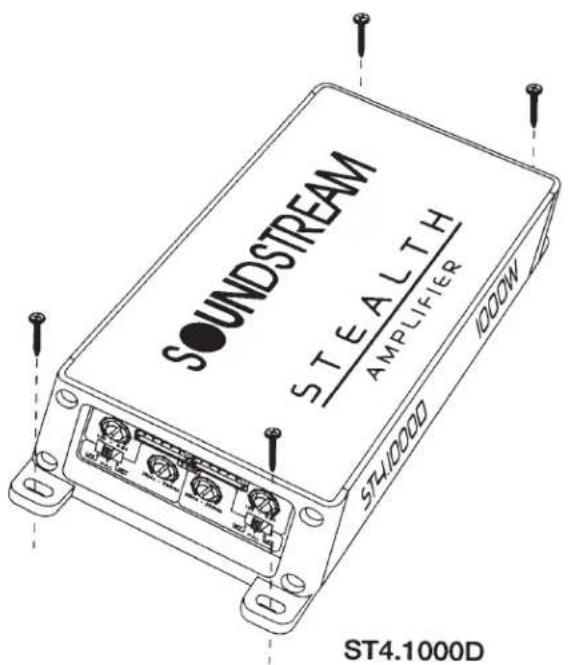
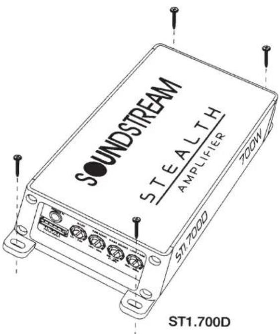
Your MICRO MINI amplifier comes with mounting feet that need to be attached to the amplifier prior to installation. Once the feet are in place, use the amplifier as a template and mark the four screw locations. Use caution to make sure there are no objects behind the installation surface that may become damaged during drilling.
The amplifier should be protected from exposure to moisture and direct sunlight. The best places to mount your amplifier are: The floor of the trunk, under the driver's seat, or on the back of the rear seat. For alternate installation locations, please consult your dealer.
WARNING
- Upside down mounting will compromise heat dissipation through the heatsink and could engage the thermal protection circuit.
- Try to avoid mounting the amplifier on a subwoofer enclosure, as extended exposure to vibration may cause malfunction of the amplifier.
- Don't mount the amplifier so that the wire connections are unprotected or are subject to pinching or damage from nearby objects.
- The DC power wire must be fused at the battery positive (+) terminal connection. Before making or breaking power connections at the amplifier power terminals, disconnect the DC power wire at the battery end.
- The power supply of the car audio system must be disconnected until the entire wiring and installation is completed.
natural_image
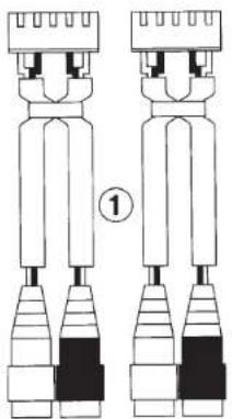
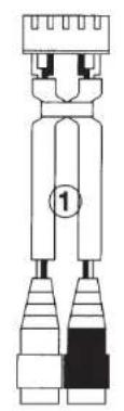
Diagram of two identical mechanical or electrical component assemblies with no visible text or symbolsKeep using RCA jack Connector
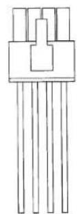
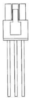
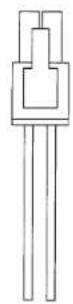
Keep using 6,8Pin Connector
ST4.1000D
natural_image
Pure electrical connector diagram without any text, numbers, or symbolsKeep using RCA jack Connector
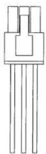
Keep using 6,8Pin Connector
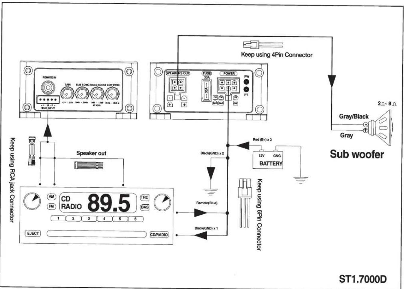
ST1.7000D
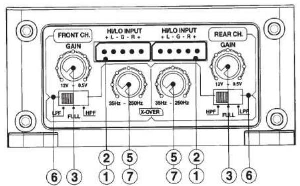
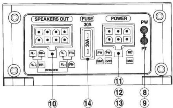
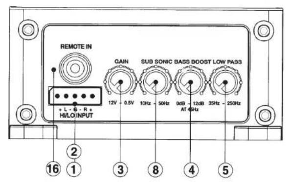
1. LINE IN (RCA) Jacks
The RCA style input jacks are for use with source units that have RCA line level outputs. A source unit with a minimum of 250mV is required for proper operation. However, this input will accept levels up to 6Vrms.
2. High Level Input
If you are installing by using a high level. you do not need to connect to the remote because.
To hear a better sound quality, you must connect the high level ground wire to the head-unit ground.
3. GAIN Control
This control is used to match the input sensitivity of the amplifier to the particular source unit that you are using.
4. BASS BOOST Control
This equalization circuit is used to enhance the low frequency response of the vehicle's interior. With up to 12dB of boost centered at 45Hz, the BASS EQ can be adjusted to meet your own personal taste.
5. LPF (Low Pass Filter Control)
This control is continuously adjustable from 35Hz through 250Hz at 12dB per octave.
6. X-OVER Switch for HI/FULL/LOW
Activates the built in electronic crossover network. Works in conjunction with the HPF and LPF adjustable controls.
7. HPF (High Pass Filter) Control
This control is continuously adjustable from 35Hz through 250Hz at 12dB per octave
8. SUB Sonic Filter
Variable subsonic filter (20Hz \~50Hz)
The subsonic filter will roll off all of the unwanted frequencies below 20Hz \~50Hz.
This will allow the amplifier to use that wasted power on the audible bandwidth.
9. POWER Indicator
The GREEN when the power is on.
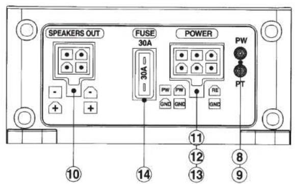
10. SPEAKER Terminals
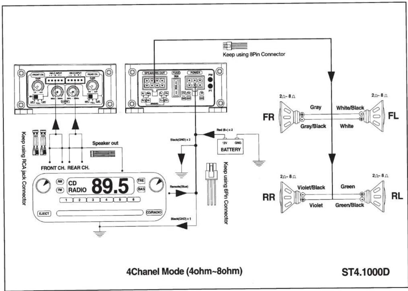
As shown in the wiring diagrams, be sure to observe speaker polarity through the system and speaker impedance. This specially tooled terminal is designed to accommodate up to 10 gauge speaker wire.
11. GND (Ground Input Connection)
A good quality ground is required for your MICRO MINI amplifier to operate at peak performance. A short length of cable the same gauge as your power cable should be used to attaché the ground terminal directly to the chassis of the vehicle.
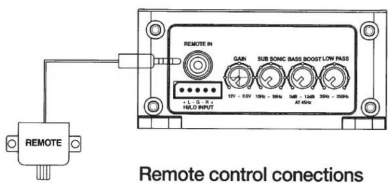
12. REMOTE (Remote Input Connection)
All MICRO MINI amplifiers can be turned on by applying 12 volts to this terminal. This can be found on the rear of the source unit in the form of an electric antenna output, or a remote output. If this is not available you can wire to the ACC position on the key. An 18 gauge wire is sufficient to run the REMOTE.
13. +BATT (Power Input Connection)
This terminal is the main power input for the amplifier and must be connected directly to the positive (+) terminal of the car battery. (see Power Cable Selection Chart on Page 9 for recommended wire gauge for each model).
14. FUSE
For convenience all MICRO MINI amplifiers utilize common automotive ATC type fuses. For continued protection in the event that a fuse blows, replace the fuse only with the same value (see specifications page).
15. REMOTE BASS BOOST CONTROL
This control adjusts the Bass Boost gain for the amplifier's speaker output (0\~+18dB) *Packed product can be different from the photograph.
ST1.7000D
WIRING AND CONNECTIONS
WARNING
Disconnect the negative (-) battery terminal before you start any wiring work! The power supply of your car audio system must be disconnected until the entire wiring installation is completed.
Your MICRO MINI amplifier requires unrestricted current to deliver peak performance, so don't "starve" your amplifier by using small power cable. Using too small of power cable can result in unnecessary over-heating of the amplifier, distortion at high volume levels and might even cause the thermal protection circuitry to shut-off the amplifier.
- Use rubber grommets when running cables through any metal or sharp plastic, to prevent accidental shorting or shearing. Make sure the cables do not interfere with normal operation of the vehicle.
- The audio signal cables (RCA interconnects) should be kept far away from any potential sources of electrical interference such as electronic vehicle management systems (relays, engine computers etc.) wiring harnesses, fuel pumps etc.
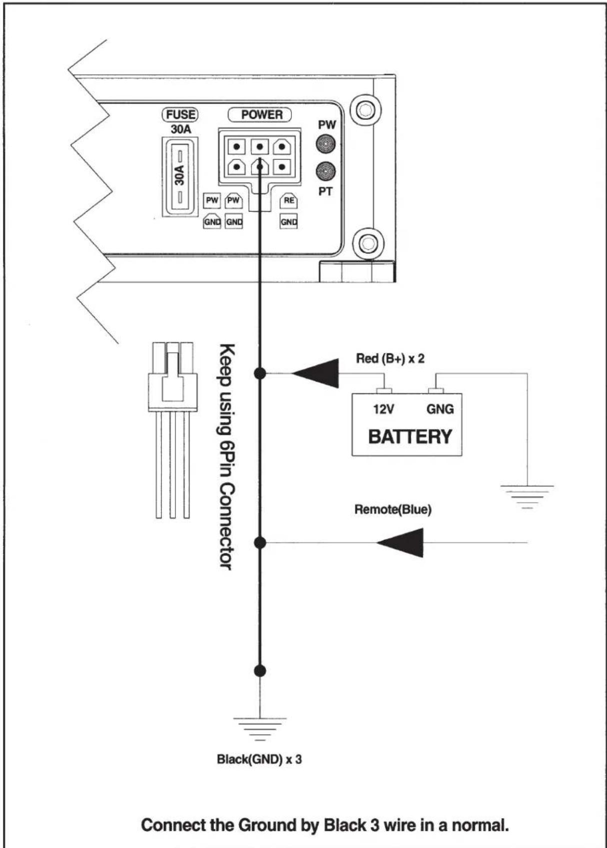
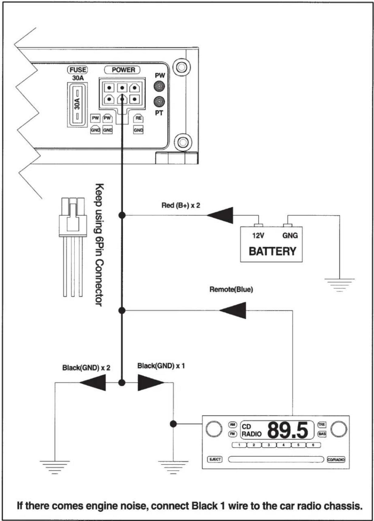
These amplifiers are designed to work within a 10 to 16.8 volt DC range. Before any wires are connected, the vehicles electrical system should be checked for correct voltage supply with the help of a voltmeter.
First, check the voltage at the battery with the ignition in the OFF position. The voltmeter should read no less than 12V. If your vehicles electrical system is not up to these specifications, we recommend having it checked by an auto electrician before any further installation. Once the vehicle is checked, make certain the correct cable size is used. We recommend using as large a gauge cable as possible, use the Power Cable Selection Chart to calculate the correct power wire size for your application.
Power
This amplifier should be wired directly to the vehicle battery using the appropriate size cable. Start at the vehicle battery and run the power cable through to the amplifier. Avoid running the power cable over engine components and near heater cores. The use of an inline fuse or circuit breaker is a must; this will prevent the risk of a potential fire caused by a short in your power cable. Connect the fuse holder or circuit breaker as close to the battery positive (+) terminal as possible (no farther then 18" from the battery). This fuse or circuit breaker should be no greater than the sum of the fuses found on the chassis of your amplifier (also see specifications chart). You may now connect the cable to the battery, but remember to leave the fuse out or circuit breaker "off" until all other cable connections are made.
Ground
When grounding your amplifier, locate a metal area close to the amplifier that is good source of ground (preferably the floor pan). Once again, investigate the area you wish to use for electrical wires, vacuum lines, and brake or fuel lines. Use either a wire brush or sandpaper to eliminate unwanted paint for better contact of the ground. Secure the ground cable to the body using a bolt, star washer and nut. Spread silicon over the screw and bare metal to prevent rust and possible water leaks.
Now it's time to connect the power and ground cables to the amplifier. Cut both cables to length. Strip off 1/2-inch (12mm) of the insulation so that the bare wire fits all the way in the terminal block on the side panel of the amplifier, seating it firmly so no bare wire is exposed. Use a Philips (cross) type screwdriver to loosen the +BATT and the GND connections on the amplifier. Insert the ground first, and then the +12V and please make sure that you place them into the correctly marked terminals. Then tighten the screws down securely.
Remote
This terminal must be connected to a switched +12V source. Typically, remote turn-on leads are provided at the source unit that will turn on and off the amplifier in correspondence with the source. If the source unit does not have a remote turn-on lead, then a power antenna wire can be used. If neither of these leads is available at the source unit, then a switched +12V supply must be used, like the ACC, +12V.
Run a minimum of 18 gauge wire from the amplifier location to the source of the switched +12V lead. If possible, route this wire on the same side of the vehicle as your power cable. Connect the source remote output to the wire. Go back to the amplifier and cut the wire to length. Loosen the screw terminal marked REMOTE on the amplifier using a Philips (cross) type screwdriver. Insert the stripped (bare) portion of the wire into the terminal and tighten the screw securely.
SPEAKER OUTPUT CONNECTIONS
flowchart
graph TD
    A["4Chanel Mode (4ohm-8ohm)"] --> B["Speaker out"]
    A --> C["Black(GND) x 2"]
    A --> D["Remote(Blue)"]
    A --> E["Black(GND) x 1"]
    A --> F["12V GNG BATTERY"]
    A --> G["Keep using 8Pin Connector"]
    G --> H["FR"]
    H --> I["Gray"]
    I --> J["White/Black"]
    I --> K["FL"]
    H --> L["RR"]
    L --> M["Violet/Black"]
    L --> N["Violet"]
    L --> O["Green/Black"]
    L --> P["RL"]
    style A fill:#f9f,stroke:#333
    style B fill:#ccf,stroke:#333
    style C fill:#ccf,stroke:#333
    style D fill:#ccf,stroke:#333
    style E fill:#ccf,stroke:#333
    style F fill:#ccf,stroke:#333
    style G fill:#cfc,stroke:#333
    style H fill:#fcc,stroke:#333
    style I fill:#fcc,stroke:#333
    style J fill:#fcc,stroke:#333
    style K fill:#fcc,stroke:#333
    style L fill:#fcc,stroke:#333
    style M fill:#fcc,stroke:#333
    style N fill:#fcc,stroke:#333
    style O fill:#fcc,stroke:#333
    style P fill:#fcc,stroke:#333
Mono Black Model
TROUBLESHOOTING TIPS
| Problem | Solution |
| Power LED not ON | With a Volt Ohm Meter (VOM) check:• +12 Volt power terminal (should read +12 to +16VDC).• Remote turn-on terminal (should read +12 to+16VDC).• Ground Terminal. |
| Power LED is GREEN, no output | • Check RCA connections.• Test speaker outputs with known good speaker.• Substitute known good Source Unit.• Check for signal on the RCA cable with VOM in AC position. |
| Protection LED is ON, no output and1. Amp is VERY HOT2. Amp shuts down ONLY when the vehicle is running3. Amp plays at very low volume | • Thermal protection is engaged. Check for proper impedance at speaker terminals. Also check for adequate air flow around the amplifier.• Voltage protection engaged. Voltage to the amp is not within the 10-16.8 VDC operating range.Have the battery/charging system inspected.• Short circuit protection is engaged. Check for speaker wires shorted to each other or the vehicle chassis. Speakers operating below the minimum impedance can cause this to occur. |
| Alternator noise (varies with RPM) | • Check for damaged RCA cable.• Check routing of RCA cable.• Check Source Unit for good ground.• Check amp gain setting, turn down if set too high. |
| Poor Bass Response | • Check speaker polarity, reverse the connection. of one speaker only. |
NOTE: If the RED protection L.E.D. is activated with no speakers connected to the amplifier, and all the power connections are correct, this would indicate an internal problem with the amplifier. Contact SOUND STREAM or your local dealer.
SPECIFICATIONS FOR MICRO MINI MODELS
(Due to Constant Improvement, Specifications and Parameters are subject to change without notice)
| Specification | ST4.1000D | ST1.700D | ||
| 1 | Out power | 4 Ohm RMS | 900W x 4ch | 300W x 1ch |
| 2 Ohm RMS | 125W x 4ch | 450W x 1ch | ||
| Bridged | 250W x 2ch | x | ||
| Max power | 1000W | 700W | ||
| 2 | Frequency | 20hz-30Khz (4ohm) | 20Hz-150Hz | |
| 3 | Speaker impedance | 4,8 Ohm | 2,4,8 Ohm | |
| 4 | Input sensitivity | Line (Low) | 0.5V-12.0V | 0.5V-12.0V |
| 5 | Filter Frequency | Low pass | 35-250Hz /12dB Oct. | 35-250Hz/12dB Oct. |
| High pass | 35-250Hz/12dB Oct. | x | ||
| Sub sonic filter | x | 10Hz-50Hz | ||
| Bass boost | x | 0-12dB 45Hz | ||
| 6 | Chanel separation | 50dB | x | |
| 7 | S/N Ratio | 70dB | 70dB | |
| 8 | THD | <0.05% | <0.5% | |
| 9 | Power supply | 11-16V DC | 11-16V DC | |
| 10 | Dimension (mm) WxHxL | 78.5 x 35.5 x 150 | 78.5 x 35.5 x 150 | |
| 11 | Weight (Kg) | 0.8 | 0.8 | |
| 12 | Output power TR design | Digital Full range | Class D Mono | |
| Accessories | |
| ① ② ③ ④ ⑤ ⑥ ⑦ ① Low level input Front RCA Jack Ass'y ② Low level input Rear RCA Jack Ass'y ③ High level input Front 5pin Connector Ass'y ④ High level input Rear 5pin Connector Ass'y ⑤ Power 6pin connector ⑥ Speaker 8pin connector ⑦ Mounting Screw (Unit) ST4.1000D | ① ② ③ ④ ⑤ ⑥ ⑦ ① Low level input RCA Jack Ass'y ② High level input 5pin Connector Ass'y ③ Power 4pin connector ④ Speaker 4pin connector ⑤ Mounting Screw (Unit) ⑥ Mounting Screw (Remote control) ⑦ Remote control ass'y ST1.7000D |
Remarks:
- Please note that the features shown in this manual may vary from model to model.
SOUNDSTREAM
- DIGITAL CLASS D FULL RANGE AMPLIFIERS
- CAUTION
- TECHNICAL FEATURES
- INSTALLATION EXPERIENCE
- PREPARING FOR INSTALLATION
- NOTE: The tools listed below may be required for basic installation
- INSTALLATION PRECAUTIONS
- MOUNTING THE AMPLIFIER
- MOUNTING LOCATION
- WARNING
- LINE IN (RCA) Jacks
- High Level Input
- GAIN Control
- BASS BOOST Control
- LPF (Low Pass Filter Control)
- X-OVER Switch for HI/FULL/LOW
- HPF (High Pass Filter) Control
- SUB Sonic Filter
- POWER Indicator
- SPEAKER Terminals
- GND (Ground Input Connection)
- REMOTE (Remote Input Connection)
- +BATT (Power Input Connection)
- FUSE
- REMOTE BASS BOOST CONTROL
- WIRING AND CONNECTIONS
- Power
- Ground
- Remote
- TROUBLESHOOTING TIPS
- SPECIFICATIONS FOR MICRO MINI MODELS
- Remarks:
- SOUNDSTREAM
Brand : Soundstream
Model : Stealth ST4.1000D
Category : Receiver