
RX-70-4K-SCL - AV Extender WyreStorm - Free user manual and instructions
Find the device manual for free RX-70-4K-SCL WyreStorm in PDF.


| Product Type | HDMI Extender over Single CAT5e/6 |
| Model | RX-70-4K-SCL |
| Brand | WyreStorm |
| Maximum Distance | 70 meters (230 ft) at 4K@60Hz |
| Supported Resolution | Up to 4K@60Hz (YUV 4:4:4) |
| HDCP Support | HDCP 2.2 and 1.4 |
| Video Bandwidth | 18 Gbps |
| Audio Format | Up to 7.1 LPCM, Dolby TrueHD, DTS-HD MA |
| IR Control | IR pass-through (20-60 kHz) |
| RS-232 Control | Bidirectional RS-232 pass-through |
| Power Supply | 5V DC, 1A (included) |
| Power Consumption | <2.5W |
| Dimensions (W x D x H) | 100 x 70 x 25 mm |
| Weight | 200 g |
| Operating Temperature | 0°C to 50°C |
| Storage Temperature | -20°C to 60°C |
| Humidity | 20% to 90% RH (non-condensing) |
| Connectivity | 1x RJ-45 (input), 1x HDMI (output) |
| Mounting | Desktop or wall-mountable (bracket optional) |
| Regulatory Compliance | CE, FCC, RoHS |
| Care and Cleaning | Wipe with a soft, dry cloth |
| Safety Instructions | Use only the provided power adapter; avoid moisture |
Frequently Asked Questions - RX-70-4K-SCL WyreStorm
User questions about RX-70-4K-SCL WyreStorm
0 question about this device. Answer the ones you know or ask your own.
Ask a new question about this device
Download the instructions for your AV Extender in PDF format for free! Find your manual RX-70-4K-SCL - WyreStorm and take your electronic device back in hand. On this page are published all the documents necessary for the use of your device. RX-70-4K-SCL by WyreStorm.
USER MANUAL RX-70-4K-SCL WyreStorm
WyreStorm recommends reading through this document in its entirety to become familiar with the product's features prior to starting the installation process.

CHDBT HDMI ARC HDCP 2.2

IMPORTANT! Installation Requirements
• Install the latest firmware to ensure that all features described in this document are available.
- The following items are required for Setup and Configuration.
o PC or Mac
o Telnet and Terminal software such as PuTTY.
o USB to 3-pin Port Adapter Cable (Included)
o Network router and/or switch for quick configuration after installation without the need to connect directly.
In the Box
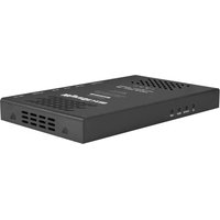
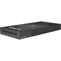
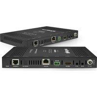
1x RX-70-4K-SCL Scaling Receiver
1x 12V DC 3A Power Supply
1x AC Cable
2x 3-pin Phoenix Connector
1x IR Emitter
1x IR Receiver
1x USB to 3-pin RS-232 Port Adapter Cable
2x Mounting Brackets
1x Quickstart Guide (this document)
Additional Information
Setup and control of the receiver for functions such EDID and audio volume commands can be found in the RX-70-4K-SCL API. This and other documentation pertaining to this product can be found in the Downloads Tab located on the product page at WyreStorm.com.
Basic Wiring Diagram

flowchart
graph TD
    A["H2 Matrix with ARC"] -->|IR RX CAB-IR-LINK (Sold Separately)| B["Control System"]
    B --> C["Amplifier"]
    C --> D["4K HDR"]
    D --> E["UHD Display"]
    E --> F["Ethernet"]
    F --> G["IR Receiver"]
    G --> H["ARC"]
    H --> I["DC 12V"]
    H --> J["EYHRENET - 3"]
    H --> K["HD&T IN"]
    H --> L["RX"]
    H --> M["HDMT OUT"]
    H --> N["AUDIO OUT"]
    H --> O["RS212"]
    P["Key: HDMI/Digital Video HDBaseT/Ethernet"] --> Q["OR"]
    R["OR"] --> S["OR"]
    T["OR"] --> U["OR"]
    V["OR"] --> W["OR"]
    X["OR"] --> Y["OR"]
    Z["OR"] --> AA["OR"]
Troubleshooting
No or Poor Quality Picture (snow or noisy image)
- Verify that power is being supplied to all devices in the system and that they are powered on.
- Verify that all source and HDBaseT connections are not loose and are functioning properly.
- Verify that the transmitter or matrix, receiving device, and display support the output resolution configured in the receiver. Refer to Video Resolutions in the Specifications table before determining cable type and length.
- Verify that the receiving device and display support the output resolution of the source.
- If transmitting 3D or 4K, verify that the HDMI cables used are 3D or 4K rated.
No or Intermittent 3rd party Device Control
- Verify that the IR cable(s) is properly terminated. See IR RX (Receiver) Wiring.
- Verify that the IR emitter is located near the IR receiver on the device.
- Verify that the connected matrix is connected to a network switch or router.
- Verify that the RS-232 cable is properly terminated per the RS-232 Wiring section.

Troubleshooting Tips:
- WyreStorm recommends using a cable tester or connecting the cable to other devices to verify functionality.
- Use a flashlight to locate the IR sensor behind any tinted panels on the device being controlled. It will likely appear as a small round disc.
Wiring and Connections
WyreStorm recommends that all wiring for the installation is run and terminated prior to making connections to the switcher. Read through this section in this entirety before running or terminating the wires to ensure proper operation and to avoid damaging equipment.
HDMI/HDBaseT Wiring

IMPORTANT! HDMI/HDBaseT Wiring Guidelines
- The use of patch panels, wall plates, cable extenders, kinks in cables, and electrical or environmental interference will have an adverse effect on HDMI and Ethernet transmission limiting performance. Steps should be taken to minimize or remove these factors completely during installation for best results.
- WyreStorm recommends using high quality HDMI cables such as WyreStorm Express to ensure the highest content performance available.
- The type of category cable used and length can restrict the available video resolution. While Cat5e can be used, WyreStorm recommends using Cat6 or higher to ensure the highest content performance available. See Video Resolutions in the Specifications table before determining cable type and length.
Cat6 Cable Performance Guide

bar
| Time (ft) | 4K Transmission (ft) | HD Transmission (ft) | |---|---|---| | 0 | 32 | 65 | | 1 | 98 | 131 | | 2 | 164 | 197 | | 3 | 197 | 230 | | 4 | 230 | 262 | | 5 | 262 | 295 | | 6 | 295 | 328 | | 7 | 328 | 362 | | 8 | 362 | 400 | | 9 | 400 | 440 | | 10 | 440 | 480 | | 11 | 480 | 520 | | 12 | 520 | 560 | | 13 | 560 | 600 | | 14 | 600 | 640 | | 15 | 640 | 680 | | 16 | 680 | 720 | | 17 | 720 | 760 | | 18 | 760 | 800 | | 19 | 800 | 840 | | 20 | 840 | 880 | | 21 | 880 | 920 | | 22 | 920 | 960 | | 23 | 960 | 1000 | | 24 | 1000 | 1040 | | 25 | 1040 | 1080 | | 26 | 1080 | 1120 | | 27 | 1120 | 1160 | | 28 | 1160 | 1200 | | 29 | 1200 | 1240 | | 30 | 1240 | 1280 | | 31 | 1280 | 1320 | | 32 | 1320 | 1360 | | 33 | 1360 | 1400 | | 34 | 1400 | 1440 | | 35 | 1440 | 1480 | | 36 | 1480 | 1520 | | 37 | 1520 | 1560 | | 38 | 1560 | 1600 | | 39 | 1600 | 1640 | | 40 | 1640 | 1680 | | 41 | 1680 | 1720 | | 42 | 1720 | 1760 | | 43 | 1760 | 1800 | | 44 | 1800 | 1840 | | 45 | 1840 | 1880 | | 46 | 1880 | 1920 | | 47 | 1920 | 1960 | | 48 | 1960 | 2000 | | 49 | 2000 | 2040 | | 50 | 2040 | 2080 | | Note: The actual values for the HD Transmission are not provided in the code. The actual values for the HD Transmission are estimated based on the visual data and may vary due to the label 'HD Transmission'.
Pin 1: White/Orange
Pin 2: Orange
Pin 3: White/Green
Pin 4: Blue
Pin 5: White/Blue
Pin 6: Green
Pin 7: White/Brown
Pin 8: Brown
Wire colors shown follow EIA/TIA-568B standard.
Control Wiring
IR TX (Emitter) Wiring
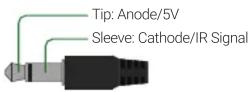
Connection for IR TX (transmit) uses a 3.5mm (1/8in) mono plug.
IR RX (Receiver) Wiring
Connection for IR RX (receive) uses a 3.5mm (1/8in) stereo jack that outputs +5V DC to power the included IR receiver.

IMPORTANT! IR TX Connection Guidelines
- 3rd party IR receivers may require a different voltage, refer to the documentation provided with the IR receiver before making any connections to avoid damaging the device.
- When connecting to an IR control system use the WyreStorm CAB-IR-LINK cable. This cable compensates for differences between the WyreStorm RX and the control systems TX connection. Visit the CAB-IR-LINK product page for details.

RS-232 Wiring
RS-232 Connection Guidelines
Most control systems and computers are DTE where pin 2 is RX, this can vary from device to device. Refer to the documentation for the connected device for pin functionality to ensure that the correct connections can be made.

Pin 1: TX (Transmit)
Pin 2: RX (Receive)
Pin 3: Ground (GND)
Wire colors shown follow EIA-561 standard.
Connecting to a PC or Control System
Connection to a PC requires the use of the included USB to 3-pin Port Adapter cable in order for a port to be provided on the PC.

Audio Wiring
The audio outputs on the receiver can be used to output de-embedded audio from the source to an external amplifier in the remote location.
Audio Out
S/PDIF Digital Coax

Analog Audio 3-pin Phoenix

Pin 1: Left Positive (+)
Pin 2: Right Positive (+)
Pin 3: Ground (GND)
Wire colors shown are for pin identificaiton only and do not represent any wiring standard.
Setup and Configuration
Note: All commands in this section are case sensitive and must be sent as defined.
Sending Commands at Start of Session
In order to send the commands listed below to an RX-70-4K-SCL the receiver must first be put into a state to receive the commands. This is due to the port for control also having functions for updating the receiver. This command only needs to be sent once at the start of communication as it will set the receiver into a state where it can receive scaler commands. Note that the receiver needs to remain in this state to be controlled via a control system.
- Connect the receiver to a matrix that is connected to a network.
- Connect the receiver to a PC via the RS-232 connection. See RS-232 Wiring.
- Open a terminal program and configure the following com port settings:
Baud Rate - 115200
Data Bits - 8 bits
Parity - None
Stop Bits - 1 bit
Flow Control - None
- Open the COM port and Send the Open Scaler Connection command CONNECT SCA
. - Once the message CONNECT SCA is received the commands for configuration and control can be sent.
Assigning a Static IP Address
While the receiver is provided with an IP address via DHCP when connected to a network or a matrix via HDBaseT, the address is not available to IP scanners. For this reason WyreStorm recommends setting a static IP address that will never change so that it can be configured once it is installed.
- Perform the steps under Sending Commands at Start of Session
- SET IPADDRESS STATIC ip4addr [IP Address] netmask [Netmask]
Replace [IP address] with the desired IP address and [Netmask] with the netmask for the network.
Example:
SET IPADDRESS STATIC ip4addr 192.168.2.128 netmask 255.255.255.0
Once a static IP address is configured the configuration commands can be sent to the receiver via IP. Be sure to record the IP address and location of the receiver so that it can be configured once it is installed.
EDID and Video Scaling Configuration
Configuration of EDID and scaling is performed via API sent to the receiver via IP or RS-232. Commands can be sent using Telnet applications such as Hercules or Putty via IP or RS-232 through the matrix. Before sending the below commands perform the steps under Sending Commands at Start of Session.
Note: While only the Video Configuration commands are shown here other commands exist to control the Audio and Video of the receiver. Refer to the RX-70-4K-SCL API located on the website for more information.
Video Configuration Commands
| Action API Command Reference Parameters | ||
| Set Input EDID | Command: SET EDID input prm<CR/LF>Return: EDID input prm<CR/LF> | prm=COPY1024x768@60_2ch 1920x1080@60_2ch1024x768@60_6ch 1920x1080@60_6ch |
| Example: Set EDID to 3840x2160@30_6chSET EDID input 3840x2160@30_6ch<CR/LF>Returns: EDID input 3840x2160@30_6ch<CR/LF> | 1280x720@60_2ch 1920x1200@60_2ch1280x720@60_6ch 1920x1200@60_6ch1280x800@60_2ch 3840x2160@30_2ch1280x800@60_6ch 3840x2160@30_6ch | |
| Configure Output Resolution (Scaling) | Command: SET SCALER prm<CR/LF>Return: SCALER prm<CR/LF>Example: Set scaling to 1920x1080@60SET SCALER 1920x1080@60<CR/LF>Returns: SCALER 1920x1080@60<CR/LF> | prm=AUTO800x600@60 1600x1200@601024x768@60 1600x900@601280x1024@60 1680x1050@601280x720@50 1920x1080@501280x720@60 1920x1080@601280x768@60 1920x1200@601280x800@60 3840x2160@241280x960@60 3840x2160@251360x768@60 3840x2160@301366x768@60 3840x2160@501440x900@60 3840x2160@60 |
Specifications
| Audio and Video | |
| Inputs 1x HDBaseT 8-pin RJ-45 female | |
| Outputs | 1x HDMI 19-pin type A1x S/PDIF Out Coaxial Digital (Audio de-embedded from HDBaseT signal)1x Audio Out 3pin Phoenix Connector (Audio de-embedded from HDBaseT signal) |
| Audio Formats | S/PDIF: 2ch PCM | Multichannel: Up to 5.1 DTS and Dolby DigitalHDMI: 2ch PCM | Multichannel: LPCM and Up to DTS-X and Dolby Atmos |
| Video Resolutions (Max) | Using HDMI1920x1080p @60Hz 12bit (15m/50ft) | @60Hz 16bit (7m/23ft)3840x2160p @24/25/30Hz 4:4:4 8bit (7m/23ft) | @24Hz 4:2:0 HDR 10bit (3m/9.8ft)4096x2160p @60Hz 8bit 4:2:0 (7m/23ft) | @60Hz 8bit 4:4:4 (7m/23ft) |
| Using Cat61920x1080 @60Hz 12bit (100m/328ft) | @60Hz 16bit (70m/230ft)3840x2160p @30Hz 4:4:4 8bit (70m/230ft) | @24Hz 4:2:0 HDR 10bit (70m/230ft)4096x2160p @60Hz 4:2:0 8bit (70m/230ft) | |
| Using Cat6a/71920x1080 @60Hz 12bit (100m/328ft) | @60Hz 16bit (100m/328ft)3840x2160p @24/25/30Hz 4:4:4 8bit (100m/328ft) | @24Hz 4:2:0 HDR 10bit (100m/328ft)4096x2160p @60Hz 4:2:0 8bit (100m/328ft) | |
| Color Depth 1080p: 16bit | 4K UHD: 8bit | HDR @24p: 10bit BT.2020 | |
| Maximum Pixel Clock 297MHz | |
| Communication and Control | |
| HDMI HDCP 2.2 | EDID (Configurable) | CEC | DVI-D supported with adapter (not included) | |
| HDBaseT HDMI | HDCP 2.2 | EDID (Configurable) | CEC | Bidirectional IR, RS-232, and Ethernet | |
| Ethernet 2x 8-pin RJ-45 female | 10/100 Mbps auto-negotiating | Bidirectional over HDBaseT | |
| IR | 1x IR TX 3.5mm (1/8in) TS Mono | 1x IR RX 3.5mm (1/8in) TRS Stereo | Transmitted over HDBaseT |
| RS-232 1x 3-pin Phoenix Connector | Bidirectional over HDBaseT when used with H2X matrix | |
| Audio Return Channel (ARC) | Returns audio from displays built-in applications via ARC HDMI Input over HDBaseT |
| Power | |
| Power Supply 12V DC 3A | |
| Max Power Consumption 16.4W | |
| Environmental | |
| Operating Temperature 32°F ~ 113°F (0°C ~ 45°C) | 10% ~ 90%, non-condensing | |
| Storage Temperature -4°F to ~ 158°F (-20°C ~ +70°C) | 10% ~ 90%, non-condensing | |
| Maximum BTU | 55.96 BTU/hr |
| Dimensions and Weight | |
| Rack Units/Wall Box | 0.56U |
| Height | 25mm/1in |
| Width | 234.4mm/9.23in |
| Depth | 143.5mm/5.65in |
| Weight | 0.66kg/1.45lbs |
| Regulatory | |
| Safety and Emission | CE | FCC | RoHS |
Note: WyreStorm reserves the right to change product specification, appearance or dimensions of this product at any time without prior notice.
Warranty Information
This product is covered by a 3 year limited parts and labor warranty. During this period there will be no charge for unit repair, component replacement or complete product replacement in the event of malfunction. The decision to repair or replace will be made by the manufacturer. This limited warranty only covers defects in materials or workmanship and excludes normal wear and tear or cosmetic damage. Visit the product page located at wyrestorm.com for additional information on this product including important technical information not provided in this document and warranty terms & conditions.


- IMPORTANT! Installation Requirements
- In the Box
- Additional Information
- Troubleshooting
- No or Poor Quality Picture (snow or noisy image)
- No or Intermittent 3rd party Device Control
- Troubleshooting Tips:
- Wiring and Connections
- HDMI/HDBaseT Wiring
- IMPORTANT! HDMI/HDBaseT Wiring Guidelines
- Control Wiring
- IR TX (Emitter) Wiring
- IR RX (Receiver) Wiring
- IMPORTANT! IR TX Connection Guidelines
- RS-232 Wiring
- RS-232 Connection Guidelines
- Connecting to a PC or Control System
- Audio Wiring
- Audio Out
- S/PDIF Digital Coax
- Analog Audio 3-pin Phoenix
- Setup and Configuration
- Sending Commands at Start of Session
- Assigning a Static IP Address
- EDID and Video Scaling Configuration
- Video Configuration Commands
- Warranty Information
Brand : WyreStorm
Model : RX-70-4K-SCL
Category : AV Extender