
MMT12CABWCAAXM8 - Air Conditioning Mabe - Free user manual and instructions
Find the device manual for free MMT12CABWCAAXM8 Mabe in PDF.


| Product Type | Mini-Split Air Conditioner (Cooling Only) |
| Brand | Mabe |
| Model | MMT12CABWCAAXM8 |
| Cooling Capacity | 12,000 BTU/h |
| Power Supply | 115 V ~ 60 Hz |
| Power Consumption | 1,300 W |
| Current | 12 A |
| Refrigerant / Charge | R410A / 540 g |
| Protection Rating (Indoor) | IPX0 |
| Protection Rating (Outdoor) | IPX4 |
| Operating Modes | Auto, Cool, Dry, Fan |
| Remote Control | Yes, with LCD display and backlight |
| Timer | 0.5 h to 24 h (ON/OFF timer) |
| Sleep Mode | Yes, automatically adjusts temperature over 7 hours |
| Clean Function | Yes, cleans evaporator (max 35 min) |
| Fungus Proof Function | Yes, prevents mold (can be set as default) |
| Airflow Direction | Up-down (auto), Left-right (manual) |
| Fan Speeds | Low, Medium, High, Auto |
| Air Filter | Washable, removable |
| Drainage | Continuous drain pipe |
| Installation Type | Wall-mounted indoor unit, outdoor unit on bracket |
| Safety Features | Grounding required, leakage protection, all-pole disconnection |
| Certifications | CE (for applicable markets) |
Frequently Asked Questions - MMT12CABWCAAXM8 Mabe
User questions about MMT12CABWCAAXM8 Mabe
0 question about this device. Answer the ones you know or ask your own.
Ask a new question about this device
Download the instructions for your Air Conditioning in PDF format for free! Find your manual MMT12CABWCAAXM8 - Mabe and take your electronic device back in hand. On this page are published all the documents necessary for the use of your device. MMT12CABWCAAXM8 by Mabe.
USER MANUAL MMT12CABWCAAXM8 Mabe
mini-split type air conditioners
for the English version, go to page 37
natural_image
Abstract geometric pattern with vertical gray bars and horizontal stripes (no text or symbols)índice
natural_image
Two technical diagrams showing a mechanical component with internal structure and directional arrows (no text or symbols)natural_image
Illustration showing a person using a solar panel to clean a bed with a bottle nearby (no text or symbols)revise antes del uso
Operation and maintenance
Safety precautions 38
Notices for use 43
Names of each part 45
Controller instructions 46
Buttons description 49
Usage 50
Clean and care 52
Troubleshooting 54
Installation service
Notices for installation 56
Install indoor unit 59
Install outdoor unit 63
Check after installation and test operation 68
Technical specifications 69
safety precautions
Incorrect installation or operation by not following these instructions may cause harm or damage to people, properties, etc. The seriousness is classified by the following indications:

WARNING:
This symbol indicates the possibility of death or serious injury.

CAUTION:
This symbol indicates the possibility of injury or damage to properties.

WARNING:
THIS APPLIANCE CAN BE USED BY CHILDREN AGED FROM 8 YEARS ABOVE AND PERSONS WITH REDUCED PHYSICAL, SENSORY OR MENTAL CAPABILITIES OR LACK OF EXPERIENCE AND KNOWLEDGE IF THEY HAVE BEEN GIVEN SUPERVISION OR INSTRUCTION CONCERNING USED OF THE APPLIANCE IN A SAFE WAY AND UNDERSTAND THE HAZARDS INVOLVE. CHILDREM SHALL NOT PLAY WITH THE APPLIANCE. CLEANING AND USER MAINTENANCE SHALL NOT BE MADE BY CHILDREN WITHOUT SUPERVISION. (Only for the AC with CE-MARKING)E-MARKING).


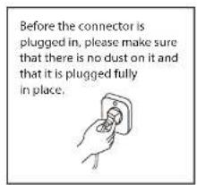


Don't share the socket with other electric appliance.

Otherwise, it may cause electric shock even fire.
Don't install air conditioner in a place where there is flammable gas or liquid. The distance between them should above 1m.

It may cause fire.
Don't use liquid or corrosive cleaning agent wipe the air conditioner and sprinkle water or other liquid either.

Don't attempt to repair the air conditioner by yourself.
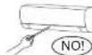
Incorrect repairs may cause electric or fire. Contact a qualified service technician for all service requirement.
Don't use air conditioner in lightning strom weather.

Don't put hands or any objects into the air inlets or outlets.


This product contains fluorinated greenhouse gases.
Refrigerant leakage contributes to climate change. Refrigerant with lower global warming potential (GWP) would contribute less to global warming that a refrigerant with higher GWP, if leaked to the atmosphere. This appliance contains a refrigerant fluid a GWP equal to 2088. This means that if 1kg of this refrigerant fluid would be leaked to the atmosphere, the impact on global warning would be 2088 times higher than 1kg of CO2 over a period of 100 years. Never try to interfere with the refrigerant circuit yourself or desassemble the product yourself and always ask a professional.
The specification of the fuse are printed on the circuit bord, such as: 3.15A/250V AC, etc. como por ejemplo: 3.15 A/250 V AC, etc.
WARNING:
MEANING OF CROSSED OUT WHEELED DUSTBIN: DO NOT DISPOSE OF ELECTRICAL APPLIANCES AS INSORTED MUNICIPAL WASTE, USE SEPARATE COLLECTION FACILITIES. CONTACT YOU LOCAL GOVERNMENT FOR INFORMA-
Don't open the windows and doors for long time when the air conditioner is running.

Otherwise, the cooling or heating capacity will be weakened.
Don't stand on the top of the outdoor unit or place heavy things on it.

This cloud cause personal injuries or damage the unit.
Don't use the air conditioner for other purposes, such as drying clothes, preserving foods, etc.

Don't apply the cold air to the body for a long time.

It will deteriorate your physical conditions and cause health problems.
Set the suitable temperature. It is recommended that the temperature difference between indoor and outdoor temperature should not be too large.
Appropriate adjustments of the setting temperature.

If your air conditioner is not fitted with a supply cord and a plug, an all-pole switch must be installed in the fixed wiring and the distance between contacts should be no less than 3.0 mm.
THE POWER SUPPLY CIRCUIT SHOULD HAVE LEAKAGE PROTECTOR AND AIR SWITCH OF WHICH THE CAPACITY SHOULD BE MORE THAN 1.5 TIMES OF THE MAXIMUM CURRENT.
REGARDING THE INSTALLATION OF THE AIR CONDITIONERS, PLEASE REFER TO THE BELOW PARAGRAPHS IN THIS MANUAL.
notices for use
the conditions of unit can't normally run
Within the temperature range provided in following table, the air conditioner may stop running and other anomalies may arise.
| cooling | outdoor | >43°C (apply to T1) |
| >52°C (apply to T3) | ||
| indoor | <18°C | |
| heating | outdoor | >24°C |
| >-7°C | ||
| indoor | >27°C |
- When the temperature is too high, the air conditioner may activate the automatic protection device, so that the air conditioner could be shut down.
- When the temperature is too low, the heat exchanger of the air conditioner may freeze, leading to water leakage or other malfunction.
- During defrost, the air conditioner will stop heating for about 5-12 minutes.
- Vapor may come out from the outdoor unit during defrost. This is not a malfunction, but a result of fast defrost.
• Heating will resume after defrost is complete.
notes for turning off
- When the air conditioner is turned off, the main controller will automatically decide whether to stop immediately or after running for dozens of seconds with lower frequency and lower air speed.
emergency operation
-
If the remote controller is lost or broken, use force switch button to operate the air conditioner.
-
If this button is pushed with the unit OFF, the air conditioner will operate in Auto mode.

- If this button is pushed with the unit ON, the air conditioner will stop running.
airflow direction adjustment
- Use up-down swing and left-right swing buttons on the remote controller to adjust the airflow direction. Refer to the operation manual of the remote controller for detail.
- For models without left-right swing function, the fins has to be moved manually.
note:
Move the fins before the unit is in operation, or your finger

names of each part
indoor unit

- Air inlet
- Force switch
- Pipe protection ring
-
Remater controller
-
Air outlet
- Air vent
- Air louver
- Air filter
- Panel
- Air inlet grille
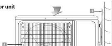
outdoor unit
air-conditioner remote controlled instructions

3. strong button
Only under the state of cooling or heating mode, press this button, the fan speed is adjusted to strong auto-matically and the LCD displays "high fan", the "strong" function is started to reach the highest cooling or heating.
4. my temp button
When it displays "my temp" button: Press this button can be used to set the my temp function. The LCD shows the actual room temperature when the function set and it shows the setting temperature when the function cancelled. This function is invalid when the appliance at the Fan mode.
5health button
You can start or stop "health" function by pressing this button.
According to environment temperature, the air conditioner can run intelligently, and choose speed auto-maticly. It can create a comfortable surroundings auto-maticly to get the most suitable temperature for body.
6. timer button
setting the "ON" timer time
a. When remote controller is at off state, press "timer" button, the LCD displays "timer on" and the timer time, the range of setting time is 0.5h to 24h.
b. You can press the "Δ" or "▼" button to adjust the timer time, each touch will be set time to increase or reduce 0.5h before 10 hours ago, after ten hours will be set time to increase or reduce 1h per pressing, to enable your required timer.
c. Press "timer" button again, to set the timer on function.
d. You can set another function to insure the suitable state after air conditioner turn on (including mode, temperature, swing, fan speed and etc). The LCD will display all your setting and keep it, when the timer reach to the set time, the air conditioner will be working according to your set automatically.
9. clean button
a. When remote controller is at the off state, press "clean" button, the wind guiding bars turn to initial postions for cooling, the A/C runs clean function with max duration 35mins. The purpose of this function is to clean dust on evaporator and dry the inside water of evaporator and to prevent the evaporator going moldy due to water deposition and boasting strange smell.
b. After setting clean function, press "clean" button again to cancel "clean" function or press "on/off" button to cancel "clean" function and start A/C.
c. The clean function will be stop working after 35 minutes running working without any operation.
note:
"clean" function can be set in parallel with time start function; in this case, time start function will be executed after "clean" function.
10. mode button
Which enables you to select different operation mode, after each pressing, the operation mode will be changed. It shows in the following display.
AUTO→COOL→DRY→HEAT→FAN→AUTO
Remark: cold wind type has no heating function.
11. sleep button
a Press the "sleep" button, the sleeping indicator light of indoor unit flashes on
b. After the setting of sleeping mode, the cooling operation enables the set temperature to increase 1°C after 1 hour and another 1°C automatically after 1 hour.
c. After the setting of sleeping mode, the heating operation enables the set temperature to drop 2°C after 1 hour and another 2°C automatically after 1 hour.
d. The air-conditioner runs in sleeping mode for 7 hours and stops automatically.
cooling. The A/C runs under heating mode (the cooling only A/C only runs under fan mode), the internal fan runs for three minutes with weak wind before stop. The purpose of this function is to dry the inside of the evaporator and to prevent the evaporator from going mouldy due to water deposition and thus dispersing strange smell.
note:
- This function has not been set in the factory. You may freely set and cancel this function. The setting method is: under off status of the A/C and the remote controller, point the remote controller toward the A/C and continuously press "fungus proof" pushbutton for one time, the buzzer keep beeping five times again after five times beep, indicating that this function is ready. In case this function has been set, unless the whole A/C is powered off or the function is manually cancelled, the A/C then has this function as default;
- To cancel the function: 1. Power off the whole A/C; 2. Under off status of the A/C and the remote controller, point the remote controller toward the A/C and continuously press "fungus proof" pushbutton for one time, the buzzer keep beeping three times again after five times beep, indicating that this function has been cancelled;
- When this function is on, it is suggested not to restart the A/C before it is completely stop;
- This function will not run in case of time stop or sleep stop.
buttons description
LCD display instruction
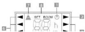
usage
fix batteries


- Slide open the cover according the direction indicated by arrowhead.
- Put into two brand new batteries (7#), position the batteries to right electric poles (+ & -).
- Put back the cover.
automatic operation mode
- Press the "mode" button, select the automatic operation mode.
- Press the "speed" button, you can select fan speed. You can select fan speed from LOW, MID, HIGH, AUTO.
- Press the "on/off" button, the operation indicator is on, the air-conditioner starts to operate the automatic mode. Press the button again, the air-conditioner stops.
cooling/Heating operation mode
(cold wind type has no heating function)
- Press the "mode" button, select the "cooling" or "heating" operation mode.
- Press the "Δ" or "V" button, set the temperature, temperature can be set at 1°C difference range from 16-32°C.
- Press the "speed" button, you can select fan speed. You can select fan speed from LOW, MID, HIGH, AUTO.
- Press the "on/off" button, the operation indicator is on, the air-conditioner starts to operate the automatic mode. Press the button again, the air-conditioner stops.
fan operation mode
- Press the "mode" button, select the Cooling or Heating
night Luminous Function of Remote Controller(Only the remote controller with this function can be used)
For your convenient use of the remote controller in the darkness without any lighting, this remote controller has blue background light and luminous pushbuttons. No matter what you press on any of the pushbutton, the background light will immediately release soft light so that you are easy to operate the remote controller. If you do not operate the controller within 10 seconds, the background light will automatically disappear.
note:
All the figures above are the displays after being initially electrified or reelectrified after power off. Inactual operations, the remote controller-screen displays related items only.
This manual introduces function for all of the remote control, maybe you press one button without any reaction, well, the air-conditioner you bought hasn't this function.
attention
- Aim the remote controller towards the receiver on the air-conditioner.
- The remote controller should be within 8 meters away from the receiver.
- No obstacles between the remote controller and receiver.
- Do not drop or throw the remote controller.
- Do not put the remote controller under the forceful sunrays or heating facilities and other heating sources.
- Use two 7# batteries, do not use the electric batteries.
- Take the batteries out of remote controller before stop its using for long.
- When the noise of transmitting signal can t be heard indoor unit or the transmission symbol on the display screen doesn t flare, batteries need be replaced.
- If reset phenomenon occurs on pressing the button of the remote controller, the electric quantity is deficient and new batteries need to be substituted.
- The waste battery should be disposed properly.reemplazarse.
clean and care
WARNING:
- BEFORE THE CLEANING OF THE AIR CONDITIONER, IT MUST BE SHUT DOWN AND THE ELECTRICITY MUST BE CUT OFF MORE THAN 5 MINUTES, OTHERWISE THERE MIGHT BE THE RISK OF ELECTRIC SHOCKS.
- DO NOT WET THE AIR CONDITIONER, WHICH CAN CAUSE AN ELECTRIC SHOCK. MAKE SURE NOT TO RINSE THE AIR CONDITIONER WHITH WATER UNDER ANY CIRCUM-STANCES.
- VOLATILE LIQUIDS SUCH AS THINNER OR GASOLINE WILL DAMAGE THE AIR CONDITIONER HOUSING, THEREFORE PLEASE CLEAN THE HOUSING OF AIR CONDITIONER ONLY WITH SOFT DRY CLOTH AND DAMP CLOTH MOISTENED WITH NEUTRAL DETERGENT.
- IN THE COURSE OF THE USING, PAY ATTENTION TO CLEANING THE FILTER REGULARY, TO PREVENT THE COVERING OF DUST WHICH MAY AFFECT THE EFFECT. IF SERVICE ENVIROMENT OF THE AIR CONDITIONER IS DUSTY, CORRESPONDINGLY INCREASE THE NUMBER OF TIMES OF CLEANING. AFTER REMOVING THE FILTER, DO
clean the panel
When the panel of the indoor unit is contaminated, clean it gently with a wrung towel using tepid water below 45°C, and do not remove the panel while cleaning.

clean the air filter
Remove the air filter
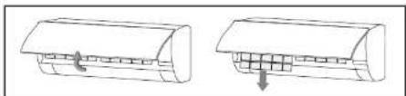
natural_image
Diagram showing two views of a mechanical component with arrows indicating direction (no text or symbols)-
Use both hands to open the panel for an angle from both ends of the panel in accordance with the direction of the arrow.
-
Release the air filter from the slot and remove it.
clean the air filter

natural_image
Two simple line drawings: one showing a car with a roof, the other showing a bowl of food (no text or symbols)check before use
- Check whether all the air inlets and outlets of the units are unblocked.
- Check whether there is blocking in the water outlet of the drain pipe, and immediately clean it up if any.
- Check the ground wire is reliably grounded.
- Check whether the remote control batteries are installed, and whether the power is sufficient.
- Check whether there is damage in the mounting bracket of the outdoor unit, and if any, please contact our local service center.
maintain after use
- Cut off the power source of the air conditioner, turn off the circuit breaker and remove the batteries from the remote control.
- Clean the filter and the unit body.
- Remove the dust and debris from the outdoor unit.
- Check whether there is damage in the mounting bracket of the outdoor unit, and ifany, please contact our local service center.
troubleshooting
CAUTION:
DO NOT REPAIR THE AIR CONDITIONER BY YOURSELF AS WRONG MAINTENANCE MAY CAUSE ELECTRIC SHOCK OR FIRE, PLEASE CONTACT THE AUTHORIZED SERVICE CENTER AND LET THE PROFESSIONALS CONDUCT THE MAINTE-
troubleshooting
phenomenon troubleshooting
| air conditionercan not operateat all. | Has the power been shut down?Is the wiring loose?Is voltage too high or too low ?(measured by professionals)Does it reach the set time for start up?Does the circuit protection device trip? |
| remotecontroller is notavailable. | Is the remote controller out of effective distanceto the indoor unit?Are there any obstructions between the controllerand the signal receptor?Is the battery exhausted? |
| cooling (Heating)efficiency is notgood. | Is the setting temperature suitable?Are air filter dirty?Is the air inlet or outlet obstructed?Is indoor fan speed set at low speed?Is there any heat source in your room? |
| indoor unit doesnot operateimmediatelywhen the airconditioner isrestarted. | If the air conditioner is turned on immediately afterit is turned off, the protective delay switch will delaythe operation for 3 to 5 minutes. |
| there is unusualsmell blowingfrom the outletafter operation is | The air conditioner itself does not have undesirableodor. If there is odor, it may be due to accumulationof the odor in the environment. Please clean the airfilter or activate the cleaning function. |
phenomenon troubleshooting
during the cooling
operation, the
indoor unit outlet
blow out mist.
This is because the indoor air is cooled rapidly.
After it runs for some time, the indoor tempera-
ture and humidity will be reduced and the mist

CAUTION:
INMEDIATELY STOP ALL OPERATIONS AND CUT OFF THE POWER SUPPLY, CONTACT OUR SERVICE CENTER LOCALLY IN FOLLOWING SITUATIONS.
- Shrill sound is heard or Unpleasant odor is emitted during the operation.
• There is an abnormal heat in power supply cord and power plug. - Accidentally pour impurities or water into the machine or the remote control.
• Air switch or protection switch often breaks.
notices for installation
important Notices

WARNING:
- BEFORE INSTALLATING, PLEASE CONTACT WITH LOCAL AUTHORIZED MAINTENANCE CENTER, IF UNIT IS NOT
requirements For Installation Position
- Avoid places of inflammable or explosive gas leakage or where there are strongly aggressive gases.
- Avoid places subject to strong artificial electric/magnetic fields.
- Avoid places subject to noise and resonance.
- Avoid severe natural conditions (e.g. heavy lampblack, strong sandy wind, direct sunshine or high temperature heat sources).
- Avoid places within the reach of children.
- Shorten the connection between the indoor and outdoor units.
- Select where it is easy to perform service and repair and where the ventilation good.
- The outdoor unit shall not be installed in any way that could occupy an aisle, stairway, exit, fire escape, catwalk or any other public area.
- The outdoor unit shall be installed as far as possible from the doors and windows of the neighbors as well as the green plants.
requirements of the mounting structure
- The mounting rack must meet the relevant national or industrial standards in terms of strength with welding and connection areas rustproofed.
- The mounting rack and its load carry surface shall be able to withstand 4 times or above the weight of the unit, or 200kg, whichever is heavier.
- The mounting rack of the outdoor unit shall be fastened with expansion bolt.
- Ensure the secure installation regardless of what type of wall on which it is installed, to prevent potential dropping that could hurt people.
electrical safety requirements
- Be sure to use the rated voltage and air conditioners dedicated circuit for the power supply, and the power cord diameter must meet the
| north america | other regions | ||
| appliance amps(A)) | AWG | rated current of appliance(A) | nominal cross-sectional area( mm^2 ) |
| 10 | 18 | >3y ≤ 6 | 0.75 |
| 13 | 16 | >6y ≤ 10 | 1 |
| 18 | 14 | >10y ≤ 16 | 1.5 |
| 25 | 12 | >16y ≤ 25 | 2.5 |
| 30 | 10 | >25y ≤ 25 | 4 |
| 40 | 8 | >32y ≤ 40 | 6 |
- The size of the power cord, power cable, fuse, and switch needed is determined by the maximum current of the unit. The maximum current is indicated on the nameplate located on the side panel of the unit. Refer to this nameplate to choose the right cable, fuse, or switch.
note:
Core number of cable refer to the detailed wiring diagram adhered on the unit which you purchased.
requirements for operations at raised height
- When carrying out installation at 2m or higher above the base level, safety belts must be worn and ropes of sufficient strength be securely fasten to the outdoor unit, to prevent falling that could cause personal injury or death as well as property loss.
grounding requirements
* The air conditioner is the type I electrical appliance and must ensure a
packing list
| packing list of the indoor unit | ||
| name | quantity | unit |
| Indoor Unit | 1 | Set |
| Remote Controller | 1 | Pc |
| Batteries(7'') | 2 | Roll |
| Instructions | 1 | Pc |
| Drain pipe 1 | Packet | |
packing list of the
| name | cantidad | unidad |
| Outdoor Unit | 1 | Set |
| Connecting pipe | 2 | Pc |
| Plastic Strap | 1 | Roll |
| Pipe Protection Ring | 1 | Pc |
| Luting (putty) 1 | Packet |
note:
All accessories shall be subject to actual packaging material, and if there is any difference, please understand.
install indoor unit
Dimension drawing of indoor unit installation
mounting plate
- The wall for installation of the indoor unit shall be hard and firm, so as to prevent vibration.
- Use the "I" type screw to fasten the peg board, horizontally mount the peg board on the wall, and ensure the lateral horizontal and longitudinal vertical.
- Pull the peg board by hand after the installation, to confirm whether it is solid.

wall-through hole
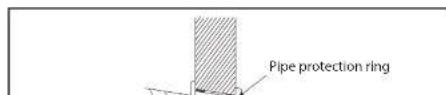
- Make a hole with an electric hammer or a water drill at the predetermined position on the wall for piping, which shall slant outwardly by 5°-10°.
- To protect the piping and the cables from being damaged running through the wall, and from the rodents that may inhabit in the hollow wall, a pipe protecting ring shall be installed and sealed with putty.
route of pipeline
- Depending on the position of the unit, the piping may be routed sideway from the left or the right (Fig 1), or vertically from the back (Fig 2) (depending on the pipe length of the indoor unit). In the case of sideway routing, cut off the outlet cutting stock of the opposite side.
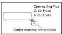
Fig 1

Fig 2
drain pipe connection
- Remove the mountings and pull the indoor unit pipe out of the housing.
- Connect the connecting pipe to the indoor unit: Aim at the pipe center, tighten the T nut with fingers, and then tighten the Taper nut with fingers, and then Taper nut with a torque wrench, and the direction is shown in diagram on the right. The torque used is shown in the following table.
tightening torque table
| the size of pipe(mm) | torque(N-m) |
| 6/ 6.35 | 15~25 |
| 9/ 9.52 | 25~40 |
| 12/ 12.7 | 45~60 |
| 15/ 15.88 | 73~78 |
wrap the piping
- Use the insulation sleeve to wrap the joint part the indoor unit and the connection pipe, and then use insulating material to pack and seal insulation pipe, to prevent generation of condensate water on the interior pipe.
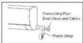
- Connect the water outlet with drain pipes, and make the connection pipe, cables, and the drain hose straight.
- Use plastic cable ties to wrap the connecting pipes, cables and drain hose. Run the pipe sloping downward.
fixing the indoor unit
- Hang the indoor unit on the peg board, and move the unit from left to right to ensure that the hook is properly positioned in the peg board.
- Push toward the lower left side and the upper right side of the unit toward the peg board, until the hook is embedded in the slot and makes a "click" sound.


note:
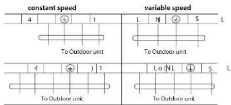
- This manual is usually includes the wiring mode for the different kind of A/C. We cannot exclude the possibility that some special type of wiring diagrams are not included.
- The diagram are for reference only. If the entity is difference with this wiring diagram, please refer to the detailed wiring diagram adhered on the unit which you purchased.
install outdoor unit
dimension drawing of outdoor unit installation externa

63
) 5
) 5

installation outdoor unit bolt
| outdoor unitsize of shape W1(W2)*H*D(mm) | A(mm) B(mm) | |
| 665(710)×420×280 | 430 280 | |
| 600(645)×485×260 | 400 | 290 |
| 660(710)×500×240 | 500 | 260 |
| 700(745)×500×255 | 460 | 260 |
| 730(780)×545×285 | 540 280 | |
| 760(810)×545×285 | 540 | 280 |
| 790(840)×550×290 | 545 | 300 |
| 800(860)×545×315 | 545 | 315 |
| 00(850)×590(690)×310 | 540 325 | |
| 825(880)×655×310 | 540 | 335 |
| 900(950)×700×350 | 630 | 350 |
| 900(950)×795×330 | 535 | 350 |
| 970(1044)×803×395 | 675 | 409 |
install the connection pipe
nota:
- Loosen the screws and remove E-parts cover from the unit.
- Connect the cables respectively to the corresponding terminals of the terminal board of the outdoor unit (see the wiring diagram), and if there are signals connected to the plug, just conduct butt joint.
- Ground wire: Remove the grounding screw out of the electric bracket, cover the grounding wire end onto the grounding screw and screw it into the grounding hole.
- Fix the cable reliably with fasteners (Pressing board).
- Put the E-parts cover back in its original place and fasten it with screws.

wiring diagram
constant speed variable speed

Connector
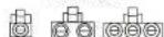
If there is a connector, connect it directly.
- This manual is usually includes the wiring mode for the different kind of A/C.
We cannot exclude the possibility that some special type of wiring diagrams are not included. - The diagram are for reference only. If the entity is difference with this wiring diagram, please refer to the detailed wiring diagram adhered on the unit which you purchased.
expelling the air
• Outdoor unit refrigerant discharging method
After the pipe side connection is complete, proceed as follows.

expelling the air
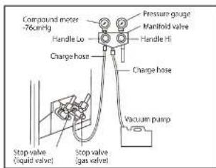
vacuum Pumping Method (R410A refrigerant evacuation must use the vacuum pumping method)
Before working on the air conditioner, remove the cover of the stop valve(gas and liquid valves)and be sure to retighten it afterward.(to prevent the potential air leakage)
- To prevent air leakage and spilling tighten all connecting nut of all flare tubes.
- Connect the stop valve, charge hose, manifold valve, and vacuum pump.
- Fully open the handle Lo of the manifold valve and apply vacuum for at least 15 minutes and check that the compound vacuum gauge reads -0.1MPa(-76cmHg).
- After applying vacuum, fully open the stop valve with a hex wrench.
- Check that both indoor and outdoor connections are free of air leakage.
outdoor condensation drainage(Heat pump type only)
check after installation and test operation
check after installation
• electrical safety check
- If the supply voltage is as required.
- If there is any faulty or miss connection in each of the power, signal and grounding wires.
- If the grounding wire of the air conditioner is securely grounded.
- installation safety check
- If the installation is secure.
- If the water drain is smooth.
- If the wiring and piping are correctly installed.
- Check that no foreign matter or tools are left inside the unit.
- leak test of the refrigerant
Depending on the installation method, the following methods may be used to check for suspect leak, on areas such as the four connections of the outdoor unit and the cores of the cut-off valves and t-valves:
- Bubble method: Apply of spray a uniform layer of soap water over the suspected leak spot and observe carefully for bubble.
- Instrument method: Checking for leak by pointing the probe of the leak detector according to the instruction to the suspect points of leak.
test operation
test operation preparation:
- Verify that all piping and connection cables are well connected.
- Confirm that the values at the gas side the liquid-side are fully open.
technical specifications
| Model | MMI12CA8WCAAXM8 | MMI12CDBWCAAXM8 |
| Supply voltage | 115 V ~ | 220-230 V ~ |
| Power consumption | 1 500 W | 1 450 W |
| Current consumption | 13 A | 6,5 A |
| Frequency | 60 Hz | 60 Hz |
| Capacity | 12 000 BTU/h | 12 000 BTU/h |
| Protection rating outdoor unit | IPX4 | IPX4 |
| Protection rating indoor unit | IPX0 | IPX0 |
| Refrigerant/Charge | R410A/820 g | R410A/820 g |
| Model | MM12HABWCAAXM8 | MM12HDBWCAAXM8 |
| Supply voltage | 115 V ~ | 220-230 V ~ |
| Power consumption | 1 500 W | 1 450 W |
| Current consumption | 13 A | 6,5 A |
| Frequency | 60 Hz | 60 Hz |
| Capacity | 12 000 BTU/h | 12 000 BTU/h |
| Protection rating outdoor unit | IPX4 | IPX4 |
| Protection rating indoor unit | IPX0 | IPX0 |
| Refrigerant/Charge | R410A/930 g | R410A/930 g |
| Model | MMI18CD8WCAAXM8 | MMI18HDBWCAAXM8 |
| Supply voltage | 220-230 V ~ | 220-230 V ~ |
| Power consumption | 1 950 W | 1 950 W |
| Current consumption | 8 A | 8 A |
| Frequency | 60 Hz | 60 Hz |
| Capacity | 18 000 BTU/h | 18 000 BTU/h |
| Model | MMT12CABWCAAXM8 | MMT12HABWCAAXM8 |
| Supply voltage | 115 V ~ | 115 V ~ |
| Power consumption | 1 300 W | 1 300 W |
| Current consumption | 12 A | 12 A |
| Frequency | 60 Hz | 60 Hz |
| Capacity | 12 000 BTU/h | 12 000 BTU/h |
| Protection rating outdoor unit | IPX4 | IPX4 |
| Protection rating indoor unit | IPX0 | IPX0 |
| Refrigerant/Charge | R410A/540 g | R410A/620 g |
| Model | MMT12CDBWCAAXM8 | MMT12HDBWCAAXM8 |
| Supply voltage | 220-230 V ~ | 220-230 V ~ |
| Power consumption | 1 300 W | 1 300 W |
| Current consumption | 5,9 A | 5,9 A |
| Frequency | 60 Hz | 60 Hz |
| Capacity | 12 000 BTU/h | 12 000 BTU/h |
| Protection rating outdoor unit | IPX4 | IPX4 |
| Protection rating indoor unit | IPX0 | IPX0 |
| Refrigerant/Charge | R410A/550 g | R410A/640 g |
| Model | MMT18HDBWCAAXM8 | MMT18CDBWCAAXM8 |
| Supply voltage | 220-230 V ~ | 220-230 V ~ |
| Power consumption | 1 950 W | 1 950 W |
| Current consumption | 9,2 A | 9,2 A |
| Frequency | 60 Hz | 60 Hz |
| Capacity | 18 000 BTU/h | 18 000 BTU/h |
notas/notes
notas/notes
(506) 4404.3001/3002
www.serviplus.co.cr
Guatemala
(502) 2476.0099
www.servplus.co.cr
Nicaragua
(505) 2248.0250
www.servipius.co.cn
República
Dominicana
- 用 R / S / A / D / C
natural_image
Abstract geometric pattern with vertical gray bars and horizontal lines, no text or symbols present
natural_image
Blank gray rectangle with no visible text, symbols, or features
- índice
- revise antes del uso
- safety precautions
- notices for use
- the conditions of unit can't normally run
- notes for turning off
- emergency operation
- airflow direction adjustment
- note:
- names of each part
- strong button
- my temp button
- 5health button
- timer button
- setting the "ON" timer time
- clean button
- mode button
- Remark: cold wind type has no heating function.
- sleep button
- buttons description
- LCD display instruction
- usage
- fix batteries
- automatic operation mode
- cooling/Heating operation mode
- (cold wind type has no heating function)
- fan operation mode
- night Luminous Function of Remote Controller(Only the remote controller with this function can be used)
- attention
- clean and care
- WARNING:
- clean the panel
- clean the air filter
- check before use
- maintain after use
- troubleshooting
- CAUTION:
- phenomenon troubleshooting
- notices for installation
- requirements For Installation Position
- requirements of the mounting structure
- electrical safety requirements
- requirements for operations at raised height
- grounding requirements
- install indoor unit
- mounting plate
- wall-through hole
- route of pipeline
- drain pipe connection
- wrap the piping
- fixing the indoor unit
- install outdoor unit
- nota:
- wiring diagram
- expelling the air
- check after installation and test operation
- check after installation
- • electrical safety check
- - installation safety check
- - leak test of the refrigerant
- test operation
- test operation preparation:
Brand : Mabe
Model : MMT12CABWCAAXM8
Category : Air Conditioning