
PT-LB20NTU - Video projector PANASONIC - Free user manual and instructions
Find the device manual for free PT-LB20NTU PANASONIC in PDF.


| Product Type | LCD Projector |
| Brand | Panasonic |
| Model | PT-LB20NTU |
| Brightness | 2000 lumens |
| Lamp Type | UHM 155 W |
| Lamp Life | Approx. 2000 hours (High mode, AI disabled) |
| Replacement Lamp | ET-LAB10 |
| Lens | F 1.8 - 2.1, f 22.0 mm - 26.2 mm |
| Power Supply | 100 V - 240 V AC, 50/60 Hz |
| Standby Power Consumption | Approx. 4 W |
| Dimensions (approx.) | 297 x 210 x 88 mm (W x D x H) |
| Weight (approx.) | 2.7 kg |
| Native Resolution | XGA (1024 x 768) |
| Network Connectivity | Yes (NT model) |
| Auto Standby Function | Yes (AUTO OFF) |
| Power Memory | Yes (POWER MEMORY) |
| Adjustable Fan | STANDARD or HIGH mode |
| Ceiling Mount Installation | Possible with ET-PKB30 kit (optional) |
| Recommended Interior Cleaning | At least once a year |
| Operating Temperature | 0°C to 40°C (32°F to 104°F) |
Frequently Asked Questions - PT-LB20NTU PANASONIC
User questions about PT-LB20NTU PANASONIC
0 question about this device. Answer the ones you know or ask your own.
Ask a new question about this device
Download the instructions for your Video projector in PDF format for free! Find your manual PT-LB20NTU - PANASONIC and take your electronic device back in hand. On this page are published all the documents necessary for the use of your device. PT-LB20NTU by PANASONIC.
USER MANUAL PT-LB20NTU PANASONIC
LCD Projector Commercial Use
Operating Instructions
HSITGNE
Model No. PT-LB20NTU
PT-LB20U
PT-LB20SU
PT-LB20VU
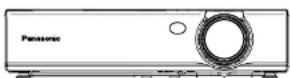

Dear Panasonic Customer:
This instruction booklet provides all the necessary operating information that you might require. We hope it will help you to get the most out of your new product, and that you will be pleased with your Panasonic LCD projector. The serial number of your product may be found on its bottom. You should note it in the space provided below and retain this booklet in case service is required.
Model number: PT-LB20NTU / PT-LB20U / PT-LB20VU / PT-LB20SU
Serial number:
IMPORTANT SAFETY NOTICE
WARNING: TO REDUCE THE RISK OF FIRE OR ELECTRIC SHOCK, DO NOT EXPOSE THIS PRODUCT TO RAIN OR MOISTURE.
Power Supply: This LCD Projector is designed to operate on 100 V – 240 V, 50 Hz/60 Hz AC, house current only.
CAUTION: The AC power cord which is supplied with the projector as an accessory can only be used for power supplies up to 125 V, 7 A. If you need to use higher voltages or currents than this, you will need to obtain a separate 250 V power cord. If you use the accessory cord in such situations, fire may result.

WARNING
RISK OF ELECTRIC
SHOCK. DO NOT OPEN

MISE EN GARDE-RISQUE DE CHOC ÉLECTRIQUE. NE PAS OLIVIR
The lightning flash with arrowhead symbol, within an equilateral triangle, is intended to alert the user to the presence of uninsulated “dangerous voltage” within the product’s enclosure that may be of sufficient magnitude to constitute a risk of electric shock to persons.

The exclamation point within an equilateral triangle is intended to alert the user to the presence of important operating and maintenance (servicing) instructions in the literature accompanying the product.
CAUTION:
This equipment is equipped with a three-pin grounding-type power plug. Do not remove the grounding pin on the power plug. This plug will only fit a grounding-type power outlet. This is a safety feature. If you are unable to insert the plug into the outlet, contact an electrician. Do not defeat the purpose of the grounding plug.
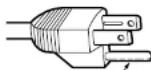
Do not remove
WARNING:
This equipment has been tested and found to comply with the limits for a Class B digital device, pursuant to Part 15 of the FCC Rules. These limits are designed to provide reasonable protection against harmful interference in a residential installation. This equipment generates, uses, and can radiate radio frequency energy and, if not installed and used in accordance with the instructions, may cause harmful interference to radio communications. However, there is no guarantee that interference will not occur in a particular installation. If this equipment does cause harmful interference to radio or television reception, which can be determined by turning the equipment off and on, the user is encouraged to try to correct the interference by one or more of the following measures:
– Reorient or relocate the receiving antenna.
– Increase the separation between the equipment and receiver.
- Connect the equipment into an outlet on a circuit different from that to which the receiver is connected.
- Consult the dealer or an experienced radio/TV technician for help.
FCC CAUTION: To assure continued compliance, use only shielded interface cables when connecting to computers or peripheral devices.
Any unauthorized changes or modifications to this equipment will void the users authority to operate.
If you use serial port to connect PC for external control of projector, you must use optional RS-232C serial interface cable with ferrite core. Any unauthorized changes or modifications to this equipment will void the user's authority to operate.
FCC RF Exposure Warning: (If provided with wireless device)
- This equipment complies with FCC radiation exposure limits set forth for an uncontrolled environment.
- This equipment has been approved for mobile operation and requires
WARNING:
- Not for use in a computer room as defined in the Standard for the Protection of Electronic Computer/Data Processing Equipment, ANSI/NFPA 75.
- For permanently connected equipment, a readily accessible disconnect device shall be incorporated in the building installation wiring;
- For pluggable equipment, the socket-outlet shall be installed near the equipment and shall be easily accessible.
Declaration of Conformity
Model Number: PT-LB20NTU/PT-LB20U/PT-LB20VU/PT-LB20SU
Trade Name: Panasonic
Responsible party: Panasonic Corporation of North America
Address: One Panasonic Way Secaucus New Jersey 07094
Telephone number: 1-800-528-8601 or 1-800-222-0741
Email: pbtsservice@panasonic.com
This device complies with Part 15 of the FCC Rules. Operation is subject to the following two conditions: (1) This device may not cause harmful interference, and (2) this device must accept any interference received, including interference that may cause undesired operation.
Contents
Preparation
IMPORTANT SAFETY NOTICE ...2
Precautions with regard to safety ....
Accessories ....10
Before use ......11
Location and function of each part....13
Getting started
Setting-up....18
Projection methods, Projector position, Projection distances
Connections......21
Connecting to computer,
Connecting to video equipment
Preparation for the remote
control unit....23
Basic operation
Turning on the power......24
Turning off the power......26
Useful functions
Correcting keystone distortion and automatic positioning.....28
Turning off the picture and sound momentarily ....29
Pausing a picture....29
Enlarging the picture....30
Adjusting the volume ....30
Displaying two screens......31
Adjustments and settings
On-screen menus ....32 Menu screens, Menu operation guide, Returning a setting to the factory default
Correcting keystone distortion...36 Adjusting the picture 37
SIGNAL MODE, Projecting sRGB-compatible pictures
Adjusting the position....41 POSITION, DOT CLOCK, CLOCK PHASE, ASPECT, RESIZING, FRAME LOCK
Changing the display
language......44
Option settings ....45 OSD, AUTO SEARCH, AUTO SIGNAL, AUTO KEYSTN, RGB2 SELECT, RGB/YPsPr, VGA60/480p, SXGA MODE, Noise Reduction (NR), BLACKBOARD, BACK COLOR, FRONT/REAR, DESK/CEILING, FAN CONTROL, LAMP POWER, LAMP RUNTIME, FUNC 1, CONTROL KEY, AUTO POW.OFF, POWER MEMORY
Setting up the security
function ....49 INPUT PASSWD, AMEND PASSWD, TEXT DISPLAY, TEXT CHANGE
Network setup....51
Care and maintenance
When the TEMP Indicator and the LAMP indicator are Illuminated....52
Cleaning and replacing
the air filter 54
Replacing the lamp unit .....55
Before calling for service.....58
Cleaning and maintenance .....59
Others
Specifications 60
Appendix 62 List of compatible signals, Projection dimensions calculation methods, Using the SERIAL connector
Dimensions 66
Precautions with regard to safety
WARNING
If you notice smoke, strange smells or noise coming from the projector, disconnect the power cord plug from the wall outlet.
- Do not continue to use the projector in such cases, otherwise fire or electric shocks could result.
- Check that no more smoke is coming out, and then contact an Authorized Service Center for repairs.
- Do not attempt to repair the projector yourself, as this can be dangerous.
Do not install this projector in a place which is not strong enough to take the full weight of the projector.
- If the installation location is not strong enough, it may fall down or tip over, and severe injury or damage could result.
Installation work (such as ceiling suspension) should only be carried out by a qualified technician.
- If installation is not carried out correctly, there is the danger that injury or electric shocks may occur.
If foreign objects or water get inside the projector, or if the projector is dropped or the cabinet is broken, disconnect the power cord from the wall outlet.
- Continued use of the projector in this condition may result in fire or electric shocks.
- Contact an Authorized Service Center for repairs.
Do not overload the wall outlet.
- If the power supply is overloaded (for example, by using too many adapters), overheating may occur and fire may result.
Do not remove the cover or modify it in any way.
- High voltages can cause fire or electric shocks.
- For any inspection, adjustment and repair work, please contact an Authorized Service Center.
Clean the power cord plug regularly to prevent it from becoming covered in dust.
- If dust builds up on the power cord plug, the resulting humidity can damage the insulation, which could result in fire. Pull the power cord plug out from the wall outlet and wipe it with a dry cloth.
- If not using the projector for an extended period of time, pull the power cord plug out from the wall outlet.
- If the power cord is used while damaged, electric shocks, short-circuits or fire may result.
- Ask an Authorized Service Center to carry out any repairs to the power cord that might be necessary.
Do not handle the power cord plug with wet hands.
- Failure to observe this may result in electric shocks.
Insert the power cord plug securely Into the wall outlet.
- If the plug is not inserted correctly, electric shocks or overheating could result.
- Do not use plugs which are damaged or wall outlet which are coming loose from the wall.
Do not place the projector on top of surfaces which are unstable.
- If the projector is placed on top of a surface which is sloped or unstable, it may fall down or tip over, and injury or damage could result.
Do not place the projector into water or let it become wet.
- Failure to observe this may result in fire or electric shocks.
Do not place the projector on soft materials such as carpets or sponge mats.
- Doing so may cause the projector to overheat, which can cause burns, fire or damage to the projector.
Do not place liquid containers on top of the projector.
- If water spills onto the projector or gets inside it, fire or electric shocks could result.
- If any water gets inside the projector, contact an Authorized Service Center.
Do not insert any foreign objects into the projector.
- Do not insert any metal objects or flammable objects into the projector or drop them onto the projector, as doing so can result in fire or electric shocks.
Keep the batteries out of the reach of Infants.
- If the batteries are swallowed, death by suffocation may result. If you believe that the batteries may have been swallowed, seek medical advice immediately.
Do not allow the + and - terminals of the batteries to come into contact with metallic objects such as necklaces or hairpins.
- Failure to observe this may cause the batteries to leak, overheat, explode or catch fire.
- Store the batteries in a plastic bag and keep them away from metallic objects.
Do not look into the lens while the projector is being used.
- Strong light is emitted from the projector's lens. If you look directly into this light, it can hurt and damage your eyes.
- Be especially careful not to let young children look into the lens. In addition, disconnect the power cord when you are away from the projector.
Do not place your hands or other objects close to the air outlet port.
- Heated air comes out of the air outlet port. Do not place your hands or face, or objects which cannot withstand heat close to this port, otherwise burns or damage could result.
Replacement of the lamp unit should only be carried out by a qualified technician.
- The lamp unit has high internal pressure. If improperly handled, explosion might result.
- The lamp unit can easily become damaged if struck against hard objects or dropped, and injury or malfunctions may result.
When replacing the lamp, allow it to cool for at least one hour before handling it.
- The lamp cover gets very hot, and touching it can cause burns.
Before replacing the lamp, be sure to disconnect the power cord from the wall outlet.
- Electric shocks or explosions can result if this is not done.
Caution
Do not cover the air inlet port or the air outlet port.
- Doing so may cause the projector to overheat, which can cause fire or damage to the projector.
- Do not place the projector in narrow, badly ventilated places such as closets or bookshelves.
- Do not place the projector on cloth or papers, as these materials could be drawn into the air inlet port.
Do not set up the projector in humid or dusty places or in places where the projector may come into contact with smoke or steam.
- Using the projector under such conditions may result in fire or electric shocks.
When disconnecting the power cord, hold the plug, not the lead.
- If the power cord itself is pulled, the lead will become damaged, and fire, short-circuits or serious electric shocks may result.
Always disconnect all cables before moving the projector.
Do not short-circuit, heat or disassemble the batteries or place them into water or fire.
- Failure to observe this may cause the batteries to overheat, leak, explode or catch fire, and burns or other injury may result.
When Inserting the batteries, make sure the polarities (+ and -) are correct.
- If the batteries are inserted incorrectly, they may explode or leak, and fire, injury or contamination of the battery compartment and surrounding area may result.
Use only the specified batteries.
- If incorrect batteries are used, they may explode or leak, and fire, injury or contamination of the battery compartment and surrounding area may result.
Insulate the battery using tape or similar before disposal.
- If the battery comes into contact with metallic objects or other batteries, it may catch fire or explode.
Do not put your weight on this projector.
- You could fall or the projector could break, and injury may result.
- Be especially careful not to let young children stand or sit on the projector.
If not using the projector for an extended period of time, disconnect the power cord plug from the wall outlet.
- If dust builds up on the power cord plug, the resulting humidity may damage the insulation, which could result in fire.
- This projector continues to draw approximately 4 W of power even when the power is turned off.
Disconnect the power cord plug from the wall outlet as a safety precaution before carrying out any cleaning.
- Electric shocks can result if this is not done.
Ask an Authorized Service Center to clean inside the projector at least once a year.
- If dust is left to build up inside the projector without being cleaned out, it can result in fire or problems with operation.
- It is a good idea to clean the inside of the projector before the season for humid weather arrives. Ask your nearest Authorized Service Center to clean the projector when required. Please discuss with the Authorized Service Center regarding cleaning costs.
We are constantly making efforts to preserve and maintain a clean environment. Please take non repairable units back to your dealer or a
NOTICE:
- This product has a High Intensity Discharge (HID) lamp that contains a small amount of mercury. It also contains lead in some components. Disposal of these materials may be regulated in your community due to environmental considerations. For disposal or recycling information please contact your local authorities, or the Electronics Industries Alliance: http://www.eiae.org
Accessories
Check that all of the accessories shown below have been included with your projector.
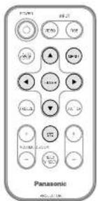
Card remote control unit (N2QADC000008 x1) 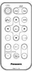 | Lithium battery for remote control unit (CR2025 x1) [xCD6] | RGB signal cable [1.8 m (5'10"), K1HA15DA0002 x1] 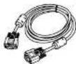 |
Power cord (K2CG3DR00006 x 1) 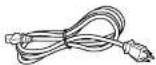 | Carrying bag (TPEP013-1 x 1) 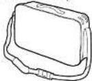 | |
| CD-ROM* (TQBH9007 x1) |
Before use
Caution when moving the projector
Be sure to attach the lens cover before moving the projector.
The projection lens is extremely susceptible to vibration and shocks. When moving the projector, use the accessory carrying bag. When placing the projector inside the carrying bag, position it so that the lens is facing upward. Do not put anything else in the bag other than the projector and the cables.
Cautions regarding setting-up
Avoid setting up in places which are subject to vibration or shocks.
The internal parts can be damaged, which may cause malfunctions or accidents.
Avoid setting up in places which are subject to sudden temperature changes, such as near an air conditioner.
The life of the lamp may be shortened.
Do not set up the projector near high-voltage power lines or near motors.
The projector may be subject to electromagnetic interference.
If installing the projector to the ceiling, ask a qualified technician to carry out all installation work.
You will need to purchase the separate installation kit (Model No.ET-PKB30). Furthermore, all installation work should only be carried out by a qualified technician.
If using this projector at high elevations (above 1 400 m), set the "FAN CONTROL" to "HIGH". (Refer to page 47.)
Failure to observe this may result in malfunctions.
Notes on use
In order to get the best picture quality
Draw curtains or blinds over any windows and turn off any lights near the screen to prevent outside light or light from indoor lamps from shining onto the screen.
Do not touch the surfaces of the lens with your bare hands.
If the surface of the lens becomes dirty from fingerprints or anything else, this will be magnified and projected onto the screen. Moreover, when not using the projector, retract the lens and then cover it with the lens cover.
Screen
Do not apply any volatile substances which may cause discoloration to the screen, and do not let it become dirty or damaged.
Lamp
The lamp may need to be replaced earlier due to variables such as individual lamp characteristics, usage conditions and the installation environment, especially when the projector is subjected to continuous use for more than 10 hours or the power is frequently turned on and off.
Liquid crystal panel
The liquid crystal panel of the projector is built with very high precision technology to provide fine picture details. Occasionally, a few non-active pixels may appear on the screen as fixed points of blue, green or red. Please note that this does not affect the performance of your LCD.
Location and function of each part
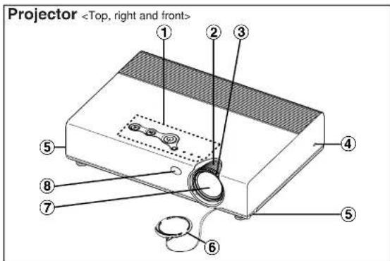
①Projector control panel (page 16)
②Zoom ring (page 25)
③Focus ring (page 25)
④Security lock
This can be used to connect a commercially-available theft-prevention cable (manufactured by Kensington). This security lock is compatible with the Microsaver Security System from Kensington.
⑤Leg adjuster buttons (L/R) (page 25)
These buttons are used to unlock the front adjustable legs. Press to adjust the angle of tilt of the projector.
⑥Lens cover
⑦Projection lens
⑧Remote control signal receptor (page 23)
Preparation
Projector
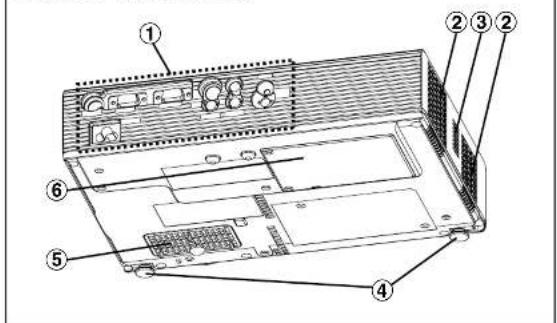
①Connector panel (page 15)
②Air outlet port
Do not cover this port.
③Speaker
④Front adjustable legs (L/R) (page 25)
⑤Air Inlet port, Air filter (page 54)
Do not cover this port.
⑥Lamp unit cover (page 55)
NOTE:
- During projection of an image, the cooling fan will operate, emitting a small noise as it operates. This noise may change depending on the ambient temperature. Turning the lamp on or off will cause this noise to increase a little.
- By using the "OPTION" menu to set "LAMP POWER" to "LOW", the operating sound of the fan can be reduced. (Refer to page 47.)
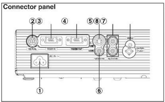
①Power Input socket (AC IN) (page 24)
The accessory power cord is connected here.
Do not use any power cord other than the accessory power cord.
②SERIAL connector (pages 21, 22 and 64)
This connector is used to connect a personal computer to the projector in order to control the projector externally. (RS-232C compatible)
③RGB1 IN connector (pages 21 and 22)
This connector is used to input RGB signals and YPBPR signals.
④RGB2 IN/1 OUT connector (pages 21, 22 and 46)
This connector is used to input or output RGB signals and YPnP8 signals.
Adjust "RGB2 SELECT" in the "OPTION" menu to select whether you want input or output with this connector.
⑤S-VIDEO IN connector (pages 22 and 42)
This connector is used to input signals from S-VIDEO-compatible equipment such as a video deck. The connector is S1 signal compatible, and it automatically switches between 16:9 and 4:3 aspect ratios in accordance with the type of signal being input.
⑥VIDEO IN connector (page 22)
Preparation
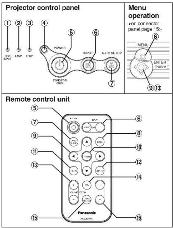
①RGB INPUT indicator
③TEMP Indicator (page 52)
This indicator illuminates if an abnormally high temperature is detected inside the projector or around it. If the temperature rises above a certain level, the power supply will be turned off automatically and the indicator will flash.
④Illumination sensor (page 39)
This sensor detects the luminance when the "DAYLIGHTVIEW" function is operating. Do not cover the projector and do not place any object on the projector when using it.
⑤POWER button (pages 24, 26 and 27)
This button is used to turn the power on and off. This button on the projector illuminates red when the projector is in standby mode, and it illuminates green when a picture starts to be projected.
⑥INPUT buttons (page 25)
These buttons are used to switch the input signals from the connected equipment.
⑦ AUTO SETUP button (pages 25 and 28)
If this button is pressed while a picture is being projected, the projection settings will be adjusted automatically in accordance with the signal being input. In addition, the angle of tilt of the projector will be automatically detected and adjusted in order to correct any keystone distortion.
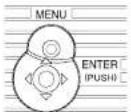
⑧MENU button (pages 32 and 34)
This button is used to display the "MAIN MENU". When a menu screen is being displayed, this button can be used to return to a previous screen or to clear the screen.
⑨Arrow (▲▼◀ and ▶) buttons (page 34)
These buttons are used to select and adjust items in the on-screen menus.
⑩ENTER button (page 34)
This button is used to accept and to activate items selected in the on-screen menus.
⑪FREEZE button (page 29)
This button is used to momentarily freeze projection so that a still picture is displayed.
⑫SHUTTER button (page 29)
This button is used to momentarily turn off the picture and sound.
⑬VOLUME +/- buttons (page 30)
These buttons are used to adjust the volume of the sound output from the projector's built-in speaker. Refer to page 33 for details on how to adjust the volume without using the remote control unit.
⑭ STD (standard) button (page 35)
This button is used to reset the projector adjustment values to the factory default settings.
⑮INDEX WINDOW button (page 31)
Setting-up
Projection methods
In way of installing projector, any one of the following four projection methods are used. Select whichever projection method matches the setting-up method. (The projection method can be set from the "OPTION" menu. Refer to pages 46 and 47 for details.)
- Front-desk projection - Front-ceiling projection
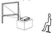
| Menu items Setting | |
| FRONT/REAR | FRONT |
| DESK/CEILING | DESK |
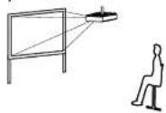
| Menu items Setting | |
| FRONT/REAR | FRONT |
| DESK/CEILING | CEILING |
- Rear-desk projection (Using a translucent screen)
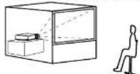
- Rear-ceiling projection (Using a translucent screen)
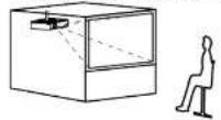
| Menu items Setting | |
| FRONT/REAR | REAR |
| DESK/CEILING | DESK |
| Menu items Setting | |
| FRONT/REAR | REAR |
| DESK/CEILING | CEILING |
NOTE:
- You will need to purchase the separate ceiling bracket (ET-PKB30) when using the ceiling installation method.
Projector position
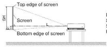
L: Projection distance
SH: Image height
SW:Image width
H1: Distance from center of lens to bottom edge of projected image
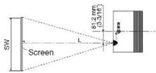
Getting started
Projection distances
PT-LB20NTU/PT-LB20U
| 4:3 Screen size (diagonal) | Projection distance (L) | Height position (H1) | |
| Wide (LW) Telephoto (LT) | |||
| -0.84 m(33') | 1.1 m(3'7') | 0.08 m(3-1'8') | |
| 1.02 m(40') | 1.2 m(3'11') | 1.4 m(4'7') | 0.09 m(3-17'32') |
| 1.27 m(50') | 1.5 m(4'11') | 1.7 m(5'6') | 0.11 m(4-5'16') |
| 1.52 m(60') | 1.8 m(5'10') | 2.1 m(6'10') | 0.14 m(5-1'2') |
| 1.78 m(70') | 2.1 m(6'10') | 2.4 m(7'10') | 0.16 m(6-9'32') |
| 2.03 m(80') | 2.4 m(7'10') | 2.8 m(9'2') | 0.18 m(7-1'16') |
| 2.29 m(90') | 2.7 m(8'10') | 3.2 m(10'5') | 0.20 m(7-27'32') |
| 2.54 m(100') | 3.0 m(9'10') | 3.5 m(11'5') | 0.22 m(8-21'32') |
| 3.05 m(120') | 3.6 m(11'9') | 4.2 m(13'9') | 0.26 m(10-7'32') |
| 3.81 m(150') | 4.5 m(14'9') | 5.3 m(17'4') | 0.33 m(12-31'32') |
PT-LB20SU
| 4:3 Screen size (diagonal) | Projection distance (L) | Height position (H1) | |
| Wide (LW) Telephoto (LT) | |||
| -0.84 m(33') | 1.1 m(3 7') | 0.08 m(3-1/8') | |
| 1.02 m(40') | 1.2 m(3'11') | 1.4 m(4 7') | 0.09 m(3-17/32') |
| 1.27 m(50') | 1.5 m(4'11') | 1.8 m(5'10') | 0.11 m(4-5/16') |
| 1.52 m(60') | 1.8 m(5 10') | 2.1 m(6'10') | 0.14 m(5-1/2') |
| 1.78 m(70') | 2.1 m(6'10') | 2.5 m(8'2') | 0.16 m(6-9/32') |
| 2.03 m(80') | 2.4 m(7'10') | 2.9 m(9'6') | 0.18 m(7-1/16') |
| 2.29 m(90') | 2.8 m(9'2') | 3.2 m(10'5') | 0.20 m(7-27/32') |
| 2.54 m(100') | 3.0 m(9'10') | 3.6 m(11'9') | 0.22 m(8-21/32') |
| 3.05 m(120') | 3.7 m(12'1') | 4.3 m(14'1') | 0.26 m(10-7/32') |
| 3.81 m(150') | 4.6 m(15'1') | 5.4 m(17'8') | 0.33 m(12-31/32') |
| 5.08 m(200') | 6.1 m(20') | 7.3 m(23'11') | 0.44 m(17-5'16') |
| 6.35 m(250') | 7.6 m(24'11') | 9.1 m(28'10') | 0.55 m(21-5/8') |
| 7.62 m(300') | 9.2 m(30'2') | 11.0 m(36'1') | 0.66 m(25-31/32') |
PT-LB20VU
| 4:3 Screen size (dlagonal) | Projection distance (L) | Height (H1) | |
| Wide (LW) Telephoto (LT) | |||
| -0.84 m(33') | 1.4 m(4'7') | 0.04 m(1-9/16') | |
| 1.02 m(40') | 1.4 m(4'7') | 1.7 m(5'6') | 0.05 m(1-15'/16') |
| 1.27 m(50') | 1.7 m(5'6') | 2.1 m(6'10') | 0.06 m(2-11/32') |
| 1.52 m(60') | 2.1 m(6'10') | 2.5 m(8'2') | 0.07 m(2-3'/4') |
| 1.78 m(70') | 2.4 m(7'10') | 2.9 m(9'6') | 0.08 m(3-1/8') |
| 2.03 m(80') | 2.8 m(9'2') | 3.4 m(11''') | 0.09 m(3-17/32') |
| 2.29 m(90') | 3.1 m(10'2') | 3.8 m(12'5') | 0.11 m(4-5'/16') |
| 2.54 m(100') | 3.5 m(11'5') | 4.2 m(13'9') | 0.12 m(4-23'/32') |
| 3.05 m(120') | 4.2 m(13'9') | 5.0 m(16'4') | 0.14 m(5-1/2') |
| 3.81 m(150') | 5.2 m(17') | 6.3 m(20'8') | 0.18 m(7-1'/16') |
| 5.08 m(200') | 7.0 m(22''11') | 8.4 m(27'5') | 0.23 m(9-1/32') |
| 6.35 m(250') | 8.7 m(28'6') | 10.6 m(34'9') | 0.29 m(11-13'/32') |
| 7.62 m(300') | 10.5 m(34'5') | 12.7 m(41'8') | 0.35 m(13-3/4') |
NOTE:
- The dimensions in the table above are approximate.
Connections
Notes on connections
- Read the instruction manual for each peripheral device carefully before connecting it.
- Turn off the power supply for all peripheral devices before making any connections.
- If the cables necessary for connection are not included with the peripheral device or available as an option, you may need to prepare a proper cable for the device concerned.
- If there is a lot of jitter in the video signal, the projected image may flicker. In such cases, it will be necessary to connect a TBC (time base corrector).
- Refer to the list on page 62 for details on compatible signals which can be input to the projector.
- Only one audio system circuit is available for the AUDIO IN L-R connectors, so if you change the audio input source, you will need to remove and insert the appropriate plugs.
Connecting to computer
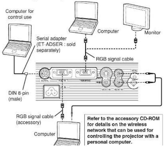
Getting started
Connecting to video equipment
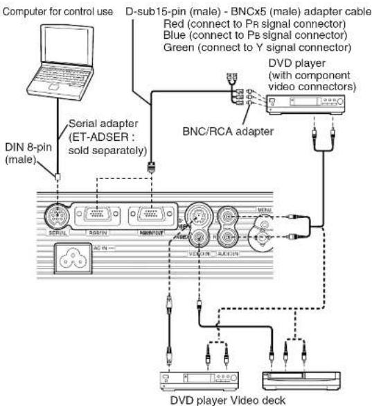
NOTE:
- If the signal cables are disconnected or if the power supply for the
computer or video desk is turned off while "D 700M" (digital zoom) as
Preparation for the remote control unit
Insert the accessory lithium battery while making sure that the polarities are correct.
①While pushing the battery holder tab to the right, pull out the battery holder. Back side
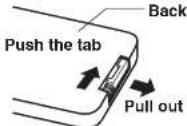
②Insert the battery Into the battery holder so that the + side is facing upward.
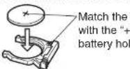
③Insert the battery holder.
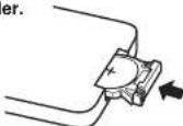
NOTE:
- Do not drop the remote control unit.
- Keep the remote control unit away from liquids.
- Remove the battery if not using the remote control unit for long periods.
- Use only CR2025 batteries as replacement batteries.
- If the remote control unit is held so that it is facing directly in front of the remote control signal receptor, the operating range is within approximately 7 m (23') from the surfaces of the receptor. Furthermore, the remote control unit can be operated from an angle of ± 30^ to the left or right and ± 15^ above or below the receptor.
- If the buttons on the remote control unit are kept pressed, the battery power will be consumed rapidly.
- If there are any obstacles in between the remote control unit and the receptor, the remote control unit may not operate correctly.
- If strong light is allowed to shine onto the remote control signal receptor,
Getting started
Turning on the power
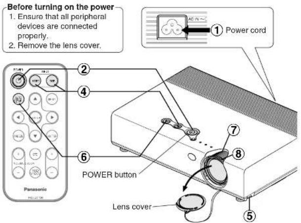
① Connect the accessory power cord to the AC IN socket.
- The POWER button on the projector will illuminate red.
② Press the POWER button.
• The POWER button on the projector will flash green. After a short period, it will illuminate green, and a picture will be projected.
③ Turn on the power of all connected devices.
• Start the play function of a device such as a DVD player.
NOTE:
④ Press the input select button to select the input signal.
| Control panel | Input select button | IN | |
| Changing signals | RGB1-S-VIDEO-RGB2-VIDEO-NETWORK | ||
| Remote control unit | Input select buttons | VIDEO | RGS |
| Changing signals | VIDEO-S-VIDEO | RGB1-RGB2-NETWORK | |
- A picture will be projected in accordance with the selected input signal.
- When a YPbPr signal is being input, "YPbPr" will be displayed instead of "RGB".
- "NETWORK" is for PT-LB20NTU only.
Follow the procedure below when you set the projector up first, and when you change the setup place.
⑤ Adjusting the angle
- While pressing the adjuster buttons, adjust the forward/back angle of tilt of the projector. Adjust so that the projected image is placed at the center of the screen.
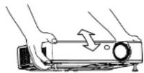
⑥ Press the AUTO SETUP button to initiate automatic positioning.
- The tilt of the projector and the input signal will be detected and keystone distortion and the position of the image will be corrected. (Refer to page 28 for details.)
AUTO SETUP
Turning off the power
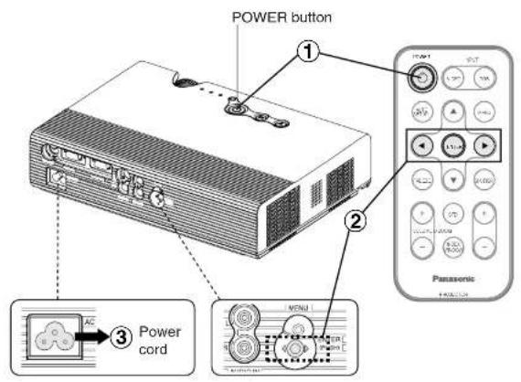
① Press the POWER button. • "POWER OFF" is displayed on the screen.
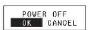
② Press the ◀ or ▶ button to select "OK", and then press the ENTER button.
- The lamp unit will switch off and the picture will stop being projected. (The POWER button on the projector will illuminate orange while the cooling fan is still operating.)
③ Disconnect the power cord after the POWER button on the projector illuminates red.
NOTE:
Direct power off function
You can disconnect the power cord during projection or immediately after use and move the projector. The cooling fan will operate by the internal power supply to cool down the lamp.
- When this function is used, it may take more time for the lamp to turn back on again compared to when the lamp cools down with the power cord connected.
- Do not put the projector in a bag while the POWER button on the projector is illuminated.
CAUTION
If not using the projector for an extended period of time, disconnect the power cord plug from the wall outlet.
- If dust builds up on the power cord plug, the resulting humidity may damage the insulation, which could result in fire.
- This projector continues to draw approximately 4 W of power even when the power is turned off.
POWER button on the projector
| POWER button status | Projector status | |
| Red | Illuminated | The projector is in standby mode and image projection is possible by pressing the POWER button. |
| Green | Flashing | The projector is preparing for projection after the power has been turned on while the POWER button on the projector is illuminated red. (After a short period, a picture will be projected.) |
| Illuminated | A picture is being projected. | |
| Illuminated | The lamp is cooling down after the power has been turned off or while direct power off function is | |
Correcting keystone distortion and automatic positioning (AUTO SETUP)
This projector detects its degree of tilt and the input signal. Keystone distortion and the position of the image can then be corrected automatically in accordance with the input signal.
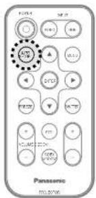
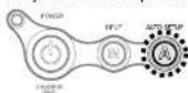
Press the AUTO SETUP button.
(When the projected image has caused keystone distortion)
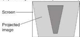
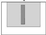
• Automatic positioning will be carried out.
Projector control panel
NOTE:
- "AUTO SEARCH" will also be carried out. (When "AUTO SEARCH" is set to "ON", refer to page 45 for details.)
- When RGB signals are being input, "DOT CLOCK", and "CLOCK PHASE" will be adjusted automatically in addition to keystone distortion and the position of the image being corrected (except when the dot clock frequency is 100 MHz or higher). Refer to page 41 for details.
- If the edges of the projected image are indistinct, or if a dark picture is being projected, the automatic setup processing may stop automatically before it is complete. If this happens, project a different picture and then press the AUTO SETUP button again.
Turning off the picture and sound momentarily (SHUTTER)
The “SHUTTER” function can be used to momentarily turn off the picture and sound from the projector when the projector is not being used for short periods of time, such as during breaks in meetings or when carrying out preparation. The projector uses less power in “SHUTTER” mode than it does in normal projection mode.
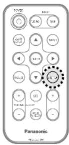
Press the SHUTTER button.
- The picture and sound will be turned off.
- Press any button on either the projector or remote control unit to return to normal operating mode.
NOTE:
- "SHUTTER" on the "MAIN MENU" is the same function.
Useful functions
Pausing a picture (FREEZE)
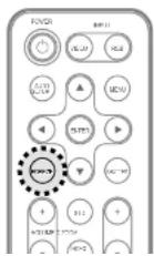
Press the FREEZE button.
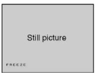
- The picture being projected will be paused.
- Press the FREEZE button again to cancel the call option.
Enlarging the picture (D.ZOOM)
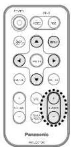
Press the D.ZOOM +/- button.
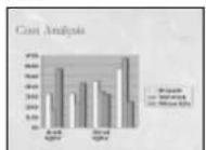
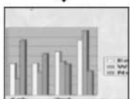
• The picture will then be enlarged to 1.5 times the normal size.
The remote control unit functions during D.ZOOM (digital zoom)
Press the D.ZOOM +/- buttons to change the enlargement ratio.
Press the ▲,▼,◀and▶buttons to move the enlarged area which you want to project.
Press the MENU button to return to the normal screen.
NOTE:
- The enlargement ratio can be changed within the range of x1 to x2, in steps of 0.1. When RGB signals are being input, the enlargement ratio can be changed within the range of x1 to x3, except when the "FRAME LOCK" is set to "ON".
- If the type of signal being input changes while the digital zoom function is being used, the digital zoom function will be cancelled.
Adjusting the volume (VOLUME)
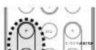
Press the VOLUME +/- button.
- Press the + button to raise the volume.
- Press the - button to lower the volume.
Displaying two screens (INDEX WINDOW)
This function lets you store a picture which is being projected into memory, so that you can display a still picture and a moving picture on the screen.
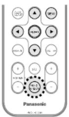
Press the INDEX WINDOW button.
- The aspect ratio of the screen changes and the image is vertically elongated in comparison to a normal image.
- When NETWORK is selected, the screen display will be switch index style, and 16 In Refer to the accesso
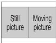
The remote control unit functions during INDEX WINDOW
Press the ▲ or ▼ button to select a screen size.
It can switch to three stages.

flowchart
graph LR
    A["Still picture"] --> B["Moving picture"]
    B --> C["Still picture"]
    C --> D["Moving picture"]
    D --> E["Still picture"]
    E --> F["Moving picture"]
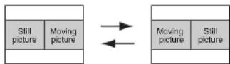
Press the ◀ or ▶ button to switch between the still picture screen and moving picture screen.
Press the ENTER button to capture the present moving picture in a still window.
Press the MENU button to return to the previous screen.
On-screen menus
Menu screens
The various settings and adjustments for this projector can be carried out by selecting the operations from on-screen menus.
The general arrangement of these menus is shown below.
MAIN MENU
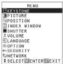

- Press the MENU button to display the "MAIN MENU". Refer to page 34 for details on how to operate the on-screen menus.
KEYSTONE correction (page 36)
KEYSTONE 0
PICTURE menu (page 37)
When an RGB signal is being input or NETWORK is selected
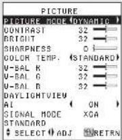
- When NETWORK is selected, "W-BAL R/G/B" settings will not be displayed. (PT-LB20NTU only)
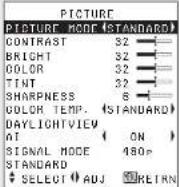
When a YPbPR signal is being input
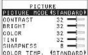
When an S-VIDEO/VIDEO signal is being input
POSITION menu (page 41)
| POSITION | |
| DOT CLOCK | 32 |
| CLOCK PHASE | 16 |
| ASPECT | 4:3 |
| RESIZING | ON |
| FRAME LOCK | OFF |
| STANDARD | |
| SELECT ENTER RETRN | |
- When an S-VIDEO/VIDEO signal is being input, "DOT CLOCK", "CLOCK PHASE" and "FRAME LOCK" settings will not be displayed.
INDEX WINDOW function (page 31)
SHUTTER function (page 29)
VOLUME adjustment Press the ENTER button, and then press the ◀or ►button to adjust the volume.
LANGUAGE menu (page 44)
| LANGUAGE | ENGLISH |
| DEUTSCH | |
| FRANÇAIS | |
| ESPAROL | |
| ITALIANO | |
| PORTUGUES | |
| SVENSKA | |
| NORSK | |
| DANSK | |
| POLSKI | |
| DEŠTINA | |
| MACYAR | |
| PYODKIM | |
| IBox | |
| SELECT ENTER RETRN | |
OPTION menu (page 45)
| OPTION | |
| OSD | ON |
| AUTO SEARCH | ON |
| AUTO SIGNAL | ON |
| AUTO KEYSIN | ON |
| RGB2 SELECT | INPUT |
| RGB/YP:PI | AUTO |
| VGABG/480P | 480P |
| SXGA MODE | SXGA |
| NR | OFF |
| BLACKBOARD | OFF |
| BACK COLOR | BLUE |
| FRONT/REAR | FRONT |
| DESK/CEILING | DESK |
| FAN CONTROL | STANDARD |
| LAMP POWER | HIGH |
| LAMP RUNTIME | 10H |
| FUNC 1 | DAYLIGHT |
| CONTROL KEY | ON |
| AUTO POW OFF | DISABLE |
| POWER MEMORY | ON |
| SELECT ADJ | RETURN |
SECURITY menu (page 49)
| SECURITY | ||
| INPUT | PASSWD | OFF |
| AMEND | PASSWD | |
| TEXT | DISPLAY | OFF |
| TEXT | CHANGE | |
| $ | SELECT | ADJ |
NETWORK menu (page 51) (PT-LB20NTU only)
| NETWORK | |
| NETWORK | 1 |
| NAME CHANGE | LB20NT |
| INPUT PASSWD | OFF |
| AREND PASSWD | |
| VEB CONTROL | ON |
| STATUS | |
Adjustments and settings
Menu operation guide
Menu operation (on connector panel)
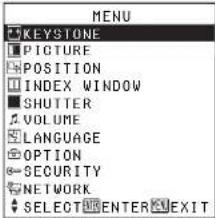
①Press the MENU button.
The "MAIN MENU" will be displayed.
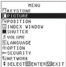
②Press the ▲ or ▼ button to select an item.
Selected item will be displayed in blue.
③Press the ENTER button to accept the
selection. The selected menu screen or adjustment screen will then be displayed. (Example: "PICTURE"
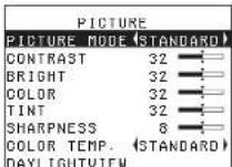
④Press the ▲ or ▼ button to select an Item, and then press the ◀ or ▶ button to change or adjust the setting.
An individual adjustment screen such as the one shown below will be displayed for bar scale items.
BRIGHT 32
The bar scale will turn green when any adjustment changes the setting from the factory set value.
Unavailable on-screen menu items
This projector has unadjustable items and unusable functions depending on the signal being input.
When an item cannot be adjusted or a function cannot be used, the corresponding on-screen menu display does not appear, and the item or function will not work even if the ENTER button is pressed.
Returning a setting to the factory default
If you press the STD (standard) button on the remote control unit, you can return settings to the factory default settings. However, the operation of this function varies depending on which screen is being displayed.
- When a menu screen is being displayed
| PICTURE | STD |
| PICTURE MODE (STANDARD) | |
| CONTRAST | 32 |
| BRIGHT | 32 |
| COLOR | 32 |
| TINT | 32 |
| SHARPNESS | 8 |
| COLOR TEMP. (STANDARD) | |
| DAYLIGHTVIEW | |
| AI | ( ON ) |
| TV-SYSTEM | ( AUTO ) |
| STILL MODE | ( OFF ) |
| STANDARD | |
| $ SELECT ENTER RETRN | |
All items displayed will be returned to their factory default settings, "STD" will be displayed in the top-right screen and the bar scale will appear white.
- When an individual adjustment screen is being displayed
BRIGHT 32
Only the item displayed will be returned to the factory default setting, and the bar scale will appear white.
NOTE:
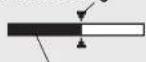
- Triangle symbols above and below the bar scale indicate the factory default setting. Items which do not have these triangle symbols cannot be returned to the factory default setting.
Indicates the standard factory default setting
Adjustments and settings
11.55
Correcting keystone distortion
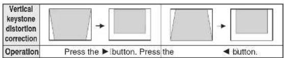
Keystone distortion is corrected automatically when the projector's automatic setup function is used, but this correction will not apply if the screen itself is tilted. In such cases, you can correct the keystone distortion manually with the following procedure.
Vertical keystone distortion correction only.
KEYSTONE 0 —1
flowchart
graph LR
    A["Vertical keystone distortion correction"] --> B["Press the ▶ button. Press the"]
    B --> C["◀ button."]
NOTE:
- If you press the AUTO SETUP button after correcting the keystone distortion manually, the automatic keystone correction function will operate and the corrected picture will return to its previous incorrect condition. To prevent this from happening, you can set "AUTO KEYSTN" in the "OPTION" menu to "OFF". (Refer to page 45.)
- Vertical keystone distortion can be corrected to ± 30^ of the angle of tilt. However, the greater the correction amount, the more the picture quality will deteriorate, and the harder it will become to achieve a good level of focus. To obtain the best picture quality, set up the projector and screen in such a way that the amount of keystone correction required is as minimal as possible.
- The picture size will also change when correction of keystone distortion is carried out.
- The ratio of length and width of an image may become incorrect depending on the amount of the keystone correction.
- Keystone distortion of the on-screen display will not be corrected.
Adjusting the picture
Press the ▲ or ▼ button on the projector or remote control unit to select an item, and then press the ◀ or ▶ button to change the setting.
For items with bar scales, press the ENTER button or the ◀ or ▶ button to display the adjustment screen, and then press the ◀ or ▶ button to make the adjustment.
When an RGB signal is being input or NETWORK is selected
| PICTURE | |
| PICTURE MODE (DYNAMIC) | |
| CONTRAST | 32 |
| BRIGHT | 32 |
| SHARPNESS | 0 |
| COLOR TEMP. (STANDARD) | |
| W-BAL R | 32 |
| W-BAL G | 32 |
| W-BAL B | 32 |
| DAYLIGHTVIEW | |
| AI | ( ON ) |
| SIGNAL MODE | XGA |
| STANDARD | |
| SELECT ADJ | RETRN |
When NETWORK is selected, "W-BAL R/G/B" settings will not be displayed. (PT-LB20NTU only)
When an YPbPr signal is being input
| PICTURE | |
| PICTURE MODE (STANDARD) | |
| CONTRAST | 32 |
| BRIGHT | 32 |
| COLOR | 32 |
| TINT | 32 |
| SHARPNESS | 6 |
When an S-VIDEO/VIDEO signal is being input
| PICTURE | |
| PICTURE MODE (STANDARD) | |
| CONTRAST | 32 |
| BRIGHT | 32 |
| COLOR | 32 |
| TINT | 32 |
| SHARPNESS | 8 |
| COLOR TEMP. (STANDARD) | |
| DAYLIGHTVIEW | |
| AI | (ON) |
| TV-SYSTEM | (AUTO) |
| STILL MODE | (OFF) |
| STANDARD | |
| SELECT ADJ | RETRN |
PICTURE MODE
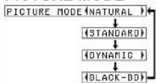
Select the picture mode that best matches the image source and room conditions.
The mode best used in dark rooms is "NATURAL". For rooms having regular lighting conditions in use, select "STANDARD". For exceptionally bright rooms, use "DYNAMIC".
"BLACK-BD" is available only when "BLACKBOARD" in the "OPTION" menu is set to "ON". Select "BLACK-BD" when projecting onto blackboards.
Adjustments and settings
CONTRAST
This adjusts the contrast of the picture. (Adjust the "BRIGHT" setting first if required before adjusting the "CONTRAST" setting.) The picture is bright: ◀ button The picture is dark: ▶ button
BRIGHT
This adjusts the darker areas (black areas) in the picture. Black areas are too light: ◀ button Dark areas are too solid: ▶ button
COLOR
(S-VIDEO/VIDEO/YPBPR only) The color is too deep: ◀ button The color is too pale: ▶ button
TINT
(NTSC/NTSC 4.43/YPBPR only) This adjusts the flesh tones in the picture.
The flesh tones are greenish: ◀ button The flesh tones are reddish: ▶ button
SHARPNESS
To soften the picture details: ◀ button To sharpen the picture details: ▶ button
COLOR TEMP.
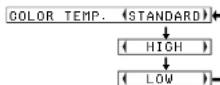
This is used to adjust the white areas of the picture if they appear bluish or reddish.
White balance R/G/B (W-BAL R/G/B)
(RGB only) This is used to adjust the white areas of the picture if they appear colorised. To make the selected color lighter: ◀ button To make the selected color stronger: ▶ button
DAYLIGHTVIEW
This adjusts the vividness of the projected images when the projector is used under bright lighting. Press the ENTER button to display the "DAYLIGHTVIEW" screen.
| DAYLIGHTVIEW | |
| MODE | AUTO |
| W-BAL | |
| SELECT ADJ | ON RETRN |
MODE
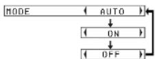
AUTO
The vividness of the projected images will be adjusted according to the lighting condition of the room.
ON
The projected images will have the highest vividness regardless of the lighting condition of the room.
OFF
"DAYLIGHTVIEW" is disabled.
NOTE:
- "AUTO" may not function correctly if any objects are placed on the projector.
- "AUTO" will be disabled when "FRONT/REAR" in the "OPTION" menu is set to "REAR".
W-BAL
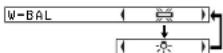
[Unreadable]
When fluorescent lamps are used for room lighting.
六
When incandescent lamps are used for room lighting.
NOTE:
- "W-BAL" is disabled when "MODE" in "DAYLIGHTVIEW" is set to "OFF".
AI
ON
The lamp is controlled according to the input signals to project images with the best quality.
OFF
"AI" is disabled.
NOTE:
- "AI" is disabled when "LAMP POWER" is set to "LOW". (Refer to page 47.)
Adjustments and settings
TV-SYSTEM
(S-VIDEO/VIDEO only)
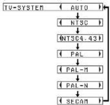
flowchart
graph TD
    A["TV-SYSTEM"] --> B["AUTO"]
    B --> C["NTSC"]
    C --> D["NTSC4.43"]
    D --> E["PAL"]
    E --> F["PAL-M"]
    F --> G["PAL-N"]
    G --> H["SECAM"]
This should normally be set to "AUTO". If the signal is of such poor quality that the correct format cannot be automatically distinguished, change the setting manually to the required TV system.
NOTE:
- When set to "AUTO", the
projector automatically
distinguishes between
NTSC/NTSC 4.43/PAL/PAL60/
PAL-M/PAL-N/SECAM signals.
STILL MODE
(S-VIDEO/VIDEO only)
To reduce flickering of still images
(vertical flicker), set "STILL MODE" to "ON".
NOTE:
- Set to "OFF" when playing back moving images.
SIGNAL MODE
(RGB/YPBPR-NETWORK only)
This displays the type of signal
which is currently being projected.
Refer to the list on page 62 for
details on each type of signal.
Projecting sRGB-compatible pictures
sRGB is an international color reproduction standard (IEC61966-2-
1) established by the International
Electrotechnical Commission (IEC).
If you would like the colors in
sRGB-compatible pictures to be
reproduced more faithfully, make
the following settings.
① Press the ▲ or ▼ button to select "PICTURE MODE", and then press the ◀ or ▶ button to select "NATURAL".
②Press the STD (standard)
button on the remote control
unit.
③ Press the ▲ or ▼ button to
select "COLOR TEMP", and
then press the ◀ or ▶ button
to select "STANDARD".
NOTE:
- sRGB is only enabled when
RGB signals are being input
(when "LAMP POWER" is set
to "HIGH", "AI" is set to "OFF".
and "MODE" in
Adjusting the position
When an RGB signal is being input, press the AUTO SETUP button first to initiate automatic positioning. If the optimum setting is not obtained when "AUTO SETUP" is carried out, adjust by the following procedure.
Press the ▲ or ▼ button on the projector or remote control unit to select an item, and then press the ◀ or ▶ button to change the setting. For items with bar scales, press the ENTER button or the ◀ or ▶ button to display the adjustment screen, and then press the ◀ or ▶ button to make the adjustment.
When an RGB/YPBPR signal is being input
| POSITION | |
| DOT CLOCK | 32 |
| CLOCK PHASE | 16 |
| ASPECT | ( 4:3 ) |
| RESIZING | ( ON ) |
| FRAME LOCK | ( OFF ) |
| STANDARD | |
| SELECT ENTER RETRN | |
When an S-VIDEO/VIDEO signal is being input
| POSITION | |
| ASPECT | 4:3 |
| RESIZING | ON |
| STANDARD | |
| SELECTED ENTER RETRN | |
POSITION
Moves the picture position.
Press the ENTER button to display the "POSITION" screen.
Press the ◀or ▶button to move the picture horizontally.
Press the ▲ or ▼ button to move the picture vertically.
| POSITION | H | 64 | |
| V | 32 |
DOT CLOCK
(RGB only)
Periodic striped pattern interference (noise) may occur when a striped pattern such as the one below is projected. If this happens, press the ◀or ►button to adjust so that any such noise is minimised.
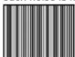
CLOCK PHASE
(RGB/YPBPR only)
Adjust the "DOT CLOCK" setting first before carrying out this adjustment. Press the ◀or ▶ button to adjust so that the noise level is least noticeable.
NOTE:
- If signals with a dot clock frequency of 100 MHz or higher are being input,
Adjustments and settings
ASPECT
(S-VIDEO/VIDEO/480i, 576i, 480p and 576p YPbPR only)
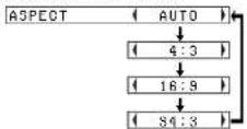
AUTO
(S-VIDEO only)
When an S1 video signal is being input, the aspect ratio is changed automatically to project a 16:9 picture.
4:3
The input signal is projected without change.
16:9
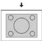
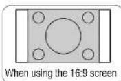
The picture is compressed to a ratio of 16:9 and projected.
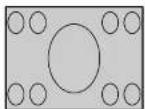
When a horizontally squeezed signal is being input.
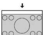
S4:3
The size of the input signal is compressed to 75% and projected. (This is useful for projecting a picture with a 4:3 aspect ratio onto a 16:9 screen.)
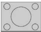
When a 4:3 signal is being input.
S1 video signals
- S1 video signals are a type of video signal with an aspect ratio of 16:9 which include a detector signal. This detector signal is output by some sources such as wide-vision video decks.
- When "ASPECT" is set to
NOTE:
- If using this projector in places such as cafes or hotels to display programs for a commercial purpose or for public presentation, note that if the aspect ratio (16:9) selection function is used to change the aspect ratio of the screen picture, you may be infringing the rights of the original copyright owner for that program under copyright protection laws.
- If a 4:3 picture is projected onto a 16:9 screen, distortion may occur around the edges of the picture so that part of the picture is no longer visible. Programs which have 4:3 aspect ratios should be viewed in 4:3 mode to give proper consideration to the aims and intentions of the original program's creator.
RESIZING
This should normally be set to "ON". (This setting is only for signals which have lower resolutions than the LCD panels. Refer to page 62 for details.)
ON
The pixel resolution of the input signal is converted to the same resolution as the LCD panels before being projected.
This may sometimes cause problems with the quality of the picture.
OFF
The input signal is projected at its original resolution, with no pixel conversion. The projected picture will be smaller than normal, so adjust the zoom setting or move the projector forwards or backwards to adjust the picture size if necessary. If set to "OFF", some features, such as "D.ZOOM" (digital zoom), "KEYSTONE" or "INDEX WINDOW" will not function.
FRAME LOCK
If the picture's condition is bad while a RGB moving picture is projected, set "FRAME LOCK" to "ON". Refer to page 62 for compatible RGB signals.
Adjustments and settings
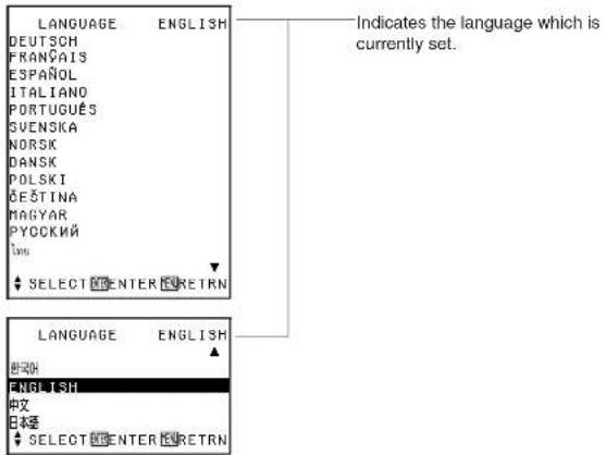
Changing the display language
Press the ▲ or ▼ button on the projector or remote control unit to select a language, then press the ENTER button to accept the setting.
Option settings
Press the ▲ or ▼ button on the projector or remote control unit to select an item, then press the ◀ or ▶ button to change the setting.
| OPTION | |
| QSD | ON |
| AUTO SEARCH | ON |
| AUTO SIGNAL | ON |
| AUTO KEYSTN | ON |
| RGB2 SELECT | INPUT |
| RGB/YP2P8 | AUTO |
| VGA60/480P | 480P |
| SXGA MODE | 5XGA |
| NR | OFF |
| BLACKBOARD | OFF |
| OPTION | |
| BACK | COLOR (BLUE) |
| FRONT/REAR (FRONT) | |
| DESK/CEILING (DESK) | |
| FAN CONTROL (STANDARD) | |
| LAMP POWER (HIGH) | |
| LAMP RUNTIME 10H | |
| FUNC 1 (DAYLIGHT) | |
| CONTROL KEY (ON) | |
| AUTO POW.OFF (DISABLE) | |
| POWER MEMORY (ON) | |
| # SELECT ADJ MORETRN | |
OSD
ON
The signal name is displayed in the top-right corner of the screen when the input signal is changed.
OFF
Use this setting when you do not want the signal name to be displayed.
HAB
AUTO SEARCH
This should normally be set to "ON"
ON
When the power is turned on and "AUTO SETUP" is running, the projector detects which signals are being input, and uses these signals for projection.
(If a picture is being projected, the signal source is not automatically changed.)
OFF
Use this setting when you do not want the signal source to be changed automatically when the power is turned on and "AUTO SETUP" is running.
AUTO SIGNAL
This should normally be set to "ON".
ON
"AUTO SETUP" will be carried out automatically when the input signal is changed.
OFF
"AUTO SETUP" will not function when the input signal is changed.
AUTO KEYSTN
This should normally be set to "ON".
ON
During "AUTO SETUP", the angle of tilt of the projector is detected and keystone distortion is corrected automatically.
OFF
Use this setting when you do not
Adjustments and settings
RGB2 SELECT
This setting is used to select the function of the RGB2 IN/1 OUT connector.
RGB/YPBPR
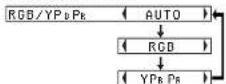
This should normally be set to "AUTO". RGB or YPbPr is selected automatically depending on the synchronising signal status. When 480i, 576i, 480p, 576p, 1 080/60i, 1 080/50i, 720/60p and some VGA480 signals are being input, select "RGB" or "YPbPr" in accordance with the input signal.
VGA60/480p
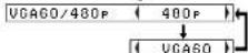
Set to "VGA60" when 59.9Hz VGA480 signals are being input (refer to page 62 for details). Set to "480p" when 480p RGB signals are being input.
SXGA MODE
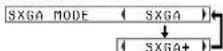
This setting is only for an SXGA signal.
SXGA
Noise Reduction (NR)
(S-VIDEO/VIDEO only)
If the signal is of such poor quality that picture interference appears, set "NR" to "ON". To turn off the "NR" feature, set to "OFF".
BLACKBOARD
Set to "ON" when "PICTURE MODE" is set to "BLACK-BD". (Refer to page 37.)
BACK COLOR
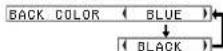
This sets the color which is projected onto the screen when no signal is being input to the projector.
FRONT/REAR
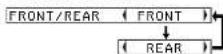
This setting should be changed in accordance with the projector setting-up method. (Refer to page 18.)
FRONT
When the projector is placed in front of a screen.
REAR
When using a translucent screen.
DESK/CEILING
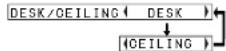
This setting should be changed in accordance with the projector setting-up method. (Refer to page 18.)
DESK
When the projector is placed on a desk or similar.
CEILING
When the projector is suspended from a ceiling using the ceiling bracket (sold separately).
FAN CONTROL
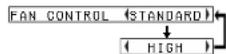
Set "FAN CONTROL" to "HIGH", when using this projector at high elevations (above 1 400 m) only.
LAMP POWER
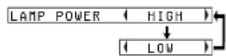
This setting changes the lamp brightness. When set to "LOW", the luminance of the lamp is reduced, but the projector uses less power, and the operating noise is also reduced. This can help to extend the lamp's operating life. If using the projector in small rooms where high luminance is not required, it is recommended that you set the
LAMP RUNTIME
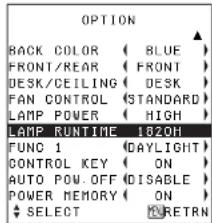
This setting displays the usage time for the lamp unit which is currently being used. When replacing the lamp unit, follow the instructions on page 56, and reset "LAMP RUNTIME" to "0".
NOTE:
- The lamp's operating life varies depending on the usage conditions (such as the "LAMP POWER" setting and the number of times the power is turned on and off).
FUNC 1
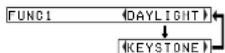
This assigns a function to the FUNC1 button of the ET-RM300 wireless remote control unit (sold separately).
DAYLIGHT
Functions in the same way as when "DAYLIGHTVIEW" is selected from the "PICTURE" menu. (page 39)
KEYSTONE
Functions in the same way as when "KEYSTONE" is selected from the "MAIN MENU". (page 36)
CONTROL KEY
To disable the buttons on the projector, set "CONTROL KEY" to "OFF". A confirmation screen will then be displayed. Select "OK" by using ◀or ▶button. To use the buttons on the projector, set to "ON" by using the remote control unit.
AUTO POW.OFF
If no signal is input to the projector for the duration of the period you set, the projector will return to standby mode. The period can be set from 15 minutes to 60 minutes in 5 minute intervals. If you don't use this feature, set it to "DISABLE". This feature will not function when using the "FREEZE" function.
POWER MEMORY
This sets the projector's start up status for when the power cord is connected.
ON
The projector will start from the same status as when the power cord was disconnected. If the power cord was disconnected during projection when the projector was used the last time, projection will start after the power cord is connected.
OFF
The projector will be in standby mode.
Setting up the security function
This projector is equipped with a security function. A password input screen can be displayed, or a company URL can be set up and displayed at the bottom of the projected image.
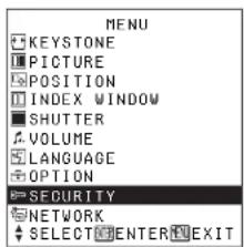
Press the ▲ or ▼ button on the projector or remote control unit to select "SECURITY", then press the ENTER button.
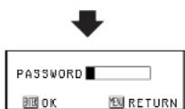
(When you use the "SECURITY" function for the first time)
Press the ▲, ▶, ▼, ◀, ▲, ▶, ▼ and ◀ buttons in order, then press the ENTER button.
(When a password change has been made before)
Type in the changed password, then press the ENTER button.

INPUT PASSWD
The password input screen can be displayed when the power is turned on. All of the controls other than the POWER button are disabled unless the password is entered correctly.
ON
"INPUT PASSWD" is enabled.
OFF
"INPUT PASSWD" is disabled. The password input screen will not be displayed when the power is turned on.
AMEND PASSWD
Passwords can be changed. Press the ENTER button to display the "AMEND PASSWD" screen.
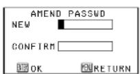
①Set a password by pressing the ▲, ▼, ◀, and ▶ buttons.
(A maximum of 8 buttons can be set.)
②Press the ENTER button.
③Enter the password again for confirmation.
④Press the ENTER button.
Password change will be
Adjustments and settings
NOTE:
- The entered password will appear as *. It will not be displayed on the screen.
- If you enter the wrong password, the letters "PASSWORD" and "NEW" will become red. Enter the correct password again.
TEXT DISPLAY
You can set text to be displayed at the bottom of the projected image at all times.
ON
"TEXT DISPLAY" is enabled.
OFF
"TEXT DISPLAY" is disabled.
TEXT CHANGE
The text which is displayed when
"TEXT DISPLAY" is set to "ON" can be changed.
Press the ENTER button to display the "TEXT CHANGE" screen.
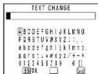
① Press the ▲, ▼, ◀ and ▶
buttons to select the characters, then press the ENTER button. (You can enter 22 characters continuously.)
- Select "BS" to delete a character.
② Press the ▲, ▼, ◀ and ▶
buttons to select "OK", then press the ENTER button.
- Select "Cancel" to cancel the change.
Network setup (PT-LB20NTU only)
You need to make adjustments on some items when controlling the projector with a personal computer by means of the wireless network. Refer to the accessory CD-ROM for details.
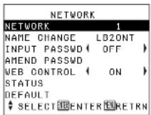
NETWORK
Select the network setting you want to use.
NAME CHANGE
The name for this projector can be set.
INPUT PASSWD
Set to "ON" if you want password confirmation to be used when controlling the projector with a personal computer by means of the wireless network.
AMEND PASSWD
Passwords can be changed.
WEB CONTROL
To control the projector with a personal computer by means of the wireless network, set the "WEB CONTROL" to "ON".
STATUS
The network settings will be displayed.
DEFAULT
Network settings can be returned to the factory default settings.
When the TEMP indicator and the LAMP indicator are illuminated
There are two indicators on the control panel of the projector which give information about the operating condition of the projector. These indicators illuminate or flash to warn you about problems that have occurred inside the projector, so if you notice that one of the indicators is on, turn off the power and check the table below for the cause of the problem.
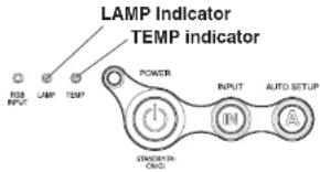
| TEMP Indicator | ||
| Indicator display | Illuminated (red)(Lamp unit on) | Flashing (red)(Lamp unit off) |
| Problem | The surrounding temperature or the temperature inside the projector has become unusually high. | The surrounding temperature or the temperature inside the projector has become dangerously high, causing the lamp unit to automatically shut off. |
| Possible cause | ● The ventilation holes may be covered.● The ambient temperature in the place of use may be too high.● The air filter may be blocked. | |
| Remedy | ● Uncover the ventilation holes.● Set up the projector in a place where the temperature is between 0 °C (32 °F) and 40 °C (104 °F) and the humidity is between 20% and 80% (with no condensation). [If you set the "FAN CONTROL" to "HIGH" (page 47), set up the projector in a place where the temperature is between 0 °C (32 °F) and 35 °C (95 °F) and the humidity is between 20% and 80% (with no condensation).] | |
| LAMP Indicator | |||
| Indicator display | Illuminated (red) | Flashing (red) | |
| Problem | It is nearly time to replace the lamp unit. | An abnormality has been detected in the lamp circuit. | |
| Possible cause | ● Does “REPLACE LAMP” appear on the screen after the projector is turned on? | ● The power may have been turned on straight away after it was turned off. | ● There may be an abnormality in the lamp circuit. |
| Remedy | ● This occurs when the operation time for the lamp unit is nearing 1 800 hours (when “LAMP POWER” has been set to “HIGH” and when “AI” has been set to “OFF”). Ask your dealer or an Authorized Service Center to replace the lamp unit. | ● Wait for a while until the lamp unit cools down before turning the power back on again. | ● Disconnect the power cord by following the procedure on page 26, and then contact an Authorized Service Center. |
NOTE:
- Be sure to disconnect the power cord by following the procedure given in "Turning off the power" on page 26 before carrying out any of the procedures in the "Remedy" column.
- If the TEMP Indicator is illuminated and the power turns off after the procedures in the "Remedy" column have been carried out, it means an abnormality has occurred. Please contact an Authorized Service Center
Care and maintenance
Cleaning and replacing the air filter
If the air filter becomes clogged with dust, the internal temperature of the projector will rise, the TEMP indicator will illuminate and the projector's power will turn off (the TEMP indicator will flash after the power is turned off). The air filter should be cleaned every 100 hours of use.
Cleaning
Use a vacuum cleaner to clean off any accumulated dust.
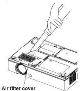
NOTE:
- If the dust cannot be cleaned by a vacuum cleaner, remove the air filter and soak it in water, and then wash out the dust by hand. Be sure to install the air filter after it has dried.
- Do not use detergent when washing the air filter.
- If the dust cannot be removed by cleaning, it is time to replace the air filter. Please consult your dealer. Furthermore, if the lamp unit is
Replacement procedure
①Turn off the power and disconnect the power cord. Be sure to disconnect the power cord by following the procedure given on page 26.
②Gently turn the projector upside down, and then remove the air filter cover.
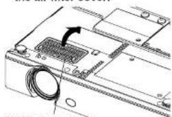
Air filter cover
③Replace the air filter, and then install the air filter cover.
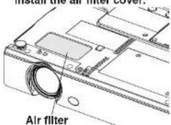
NOTE:
- Be sure to install the air filter before using the projector. If
Replacing the lamp unit
Warning
The lamp unit should only be replaced by a qualified technician.
When replacing the lamp, allow it to cool for at least one hour before handling it.
- The lamp cover gets very hot, and touching it can cause burns.
Notes on replacing the lamp unit
- The light generating lamp is made of glass, so dropping it or allowing it to hit hard objects may cause it to burst. Be careful when handling the lamp.
- Dispose of the removed old lamp with the same care that would be taken with a fluorescent light.
● A Phillips screwdriver is necessary for removing the lamp unit.
NOTE:
- The projector is not supplied with a replacement lamp unit. Please ask your dealer for details. Lamp unit product no.: ET-LAB10
CAUTION:
- Do not use any lamp unit other than the one with the product number indicated above.
Lamp unit replacement period
The lamp is a consumable product. Even when the full life of the bulb has not been exhausted, the brightness of the light will gradually decline. Therefore periodic replacement of the lamp is necessary.
The intended lamp replacement interval is 2000 hours, but it is possible that the lamp may need to be replaced earlier due to variables such as a particular lamp's characteristics, usage conditions and the installation environment. Early preparation for lamp replacement is encouraged. The lamp will automatically shut off after approximately 10 minutes when 2000 hours of use have been reached because of a much greater chance of it exploding after this time.
NOTE:
- The usage hours explained above are for when "LAMP POWER" in the "OPTION" menu has been set to "HIGH" and when "AI" in the "PICTURE" menu has been set to "OFF". If "LAMP POWER" is set to "LOW", or "AI" is set to "ON", the life of the lamp can be extended.
- While 2000 hours is the intended replacement interval,
| REPLACE LAMP | LAMP indicatorOn-screen display | |
| More than 1 800 hours | Displayed for 30 seconds. Pressing any button will clear the display. | Illuminates red during image projection and standby mode. |
| More than 2 000 hours | Remains displayed until any button is pressed. |
Lamp unit replacement procedure
NOTE:
- If the lamp usage time has passed 2 000 hours (when "LAMP POWER" has been set to "HIGH" and when "AI" has been set to "OFF"), the projector will switch to standby mode after approximately 10 minutes of operation. The steps ⑦ to ⑪ on the next page should thus be completed within 10 minutes.
①Disconnect the power cord from the projector by following the procedure on page 26, and check that the area around the lamp unit has cooled down.
②Use a Phillips screwdriver to turn the lamp unit cover fixing screws at the bottom of the projector, and then remove the lamp unit cover.
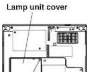
③Use a Phillips screwdriver to loosen the two lamp unit fixing screws until the screws turn freely. Then hold the handle of the lamp unit and gently pull it out from the projector.
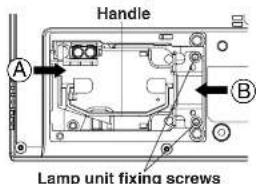
④Insert the new lamp unit while making sure that the direction of Insertion is correct, and then
⑤Install the lamp unit cover, and then use a Phillips screwdriver to securely tighten the lamp unit cover fixing screws.
NOTE:
- Be sure to install the lamp unit and the lamp unit cover securely. If they are not securely installed, it may cause the protection circuit to operate so that the power cannot be turned on.
⑥Connect the power cord.
⑦Press the POWER button so that a picture is projected onto the screen.
NOTE:
- If the power cord was disconnected during projection when the projector was used the last time, projection will start after the power cord is connected (when "POWER MEMORY" in the "OPTION" menu is set to "ON"). Refer to page 48 for details.
⑧Press the MENU button to display the "MAIN MENU", and then press the ▲ or ▼button to select "OPTION".
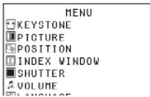
⑨ Press the ENTER button to display the "OPTION" menu, and then press the ▲ or ▼ button to select "LAMP RUNTIME".
⑩Press and hold the ENTER button for approximately 3 seconds.
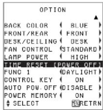
The "LAMP RUNTIME" will change to "TIME RESET [POWER OFF]".
NOTE:
- If the MENU button is pressed, the lamp time resetting screen will be cancelled.
④Turn off the power and
Before calling for service
Before calling for service, check the following points.
| Problem Possible cause | Page | |
| Power does not turn on. | ● The power cord may not be connected.● The main power supply is not being supplied to the wall outlet.● TEMP indicator is illuminated or flashing.● LAMP indicator is illuminated or flashing.● The lamp unit cover has not been securely installed. | — |
| 52 | ||
| 53 | ||
| — | ||
| No picture appears. | ● The video signal input source may not be connected properly.● The input selection settling may not be correct.● The “BRIGHT” adjustment setting may be at the minimum possible settling.● The “SHUTTER” function may be in use. | — |
| 25 | ||
| 38 | ||
| 29 | ||
| The picture Is fuzzy. | ● The lens cover may still be attached to the lens.● The lens focus may not have been set correctly.● The projector may not be at the correct distance from the screen.● The lens may be dirty.● The projector may be tilted too much. | — |
| 25 | ||
| 19, 20 | ||
| — | ||
| 18 | ||
| The color Is pale or grayish. | ● “COLOR” or “TINT” adjustment may be incorrect.● The input source which is connected to the projector may not be adjusted correctly. | 38 |
| — | ||
| No sound can be heard. | ● The audio signal source may not be connected properly.● The volume adjustment may be at the lowest possible settling. | — |
| 30, 33 | ||
| The remote control unit does not operate. | ● The battery may be weak.● The battery may not be inserted correctly.● The remote control signal receptor on the projector may be obstructed.● The remote control unit may be out of the operation range. | — |
| 23 | ||
| 23 | ||
| 23 | ||
| The buttons on the projector do | ● The “CONTROL KEY” may be set to “OFF”.In order to set the “CONTROL KEY” to “ON” | 48 |
| The picture does not display correctly. | ● The signal format (“TV-SYSTEM”) may not be set correctly.● There may be a problem with the video tape or other signal source.● A signal which is not compatible with the projector may be being input. | 40—62 |
| Picture from computer does not appear. | ● The cable may be too long.● The external video output for the laptop computer may not be set correctly.(You may be able to change the external output settings by pressing the [Fn]+[F3] or [Fn]+[F10] keys simultaneously. The actual method varies depending on the type of computer, so refer to the documentation provided with your computer for further details.)● If an RGB INPUT indicator is turned off, the video signals may not be output from the computer.● “RGB2 SELECT” in the “OPTION” menu is set to “OUTPUT” when the signals are input to RGB2 IN/1 OUT connector. | --------1646 |
Cleaning and maintenance
Before carrying out cleaning and maintenance, be sure to disconnect the power cord plug from the wall outlet.
Wipe the cabinet with a soft, dry cloth.
If the cabinet is particularly dirty, soak the cloth in water with a small amount of neutral detergent in it, squeeze the cloth very well, and then wipe the cabinet. After cleaning, wipe the cabinet dry with a dry cloth. If using a chemically-treated cloth, read the instructions supplied with the cloth before use.
Do not wine the lane with a cloth that is dusty or which produces lint
Specifications
Power supply: 100 V - 240 V -, 50 Hz/60 Hz
Power consumption: 220 W [During standby (when fan is
stopped): Approx. 4 W]
Amps: 2.5 A - 1.3 A
LCD panel:
Panel size (diagonal):
PT-LB20NTU/PT-LB20U/PT-LB20SU: 0.7 type (17.78 mm)
PT-LB20VU: 0.6 type (15.24 mm)
Aspect ratio: 4:3
Micro lens array: Available
Display method: 3 transparent LCD panels (RGB)
Drive method: Active matrix method
Pixels:
PT-LB20NTU/PT-LB20U/PT-LB20VU: 786 432 (1 024 x 768) x 3 panels
PT-LB20SU: 480 000 (800 x 600) x 3 panels
Lens: Manual zoom (1 - 1.2) / Manual focus
PT-LB20NTU/PT-LB20U/PT-LB20VU: F 1.7 - 1.9 f 21.5 mm - 25.8 mm
PT-LB20SU: F 1.8 - 2.1 f 22.0 mm - 26.2 mm
Lamp: UHM lamp (155 W)
Luminosity:
PT-LB20NTU/PT-LB20U/PT-LB20SU: 2 000 lm
PT-LB20VU: 1 600 lm
Scanning frequency (for RGB signals):
Horizontal scanning frequency: 15 kHz - 91 kHz
Vertical scanning frequency: 50 Hz - 85 Hz
Dot clock frequency: Less than 100 MHz
YPbPn signals:
480i, 576i, 480p, 576p, 1 080/60i,
1 080/50i, 720/60p
Color system:
7 (NTSC/NTSC 4.43/PAL/PAL-M/PAL-N/
PAL60/SECAM)
Projection size:
838.2 mm - 7 620 mm (33" - 300")
Throw distance:
PT-LB20NTU/PT-LB20U: 1.1 m - 10.7 m (3'7" - 35'1")
PT-LB20SU: 1.1 m - 11.0 m (3'7" - 36'1")
PT-LB20VU: 1.4 m - 12.7 m (4'7" - 41'8")
Optical axis shift
PT-LB20NTU/PT-LB20U/PT-LB20SU: 6:1 (fixed)
PT-LB20VU: 12:1 (fixed)
Connectors
RGB IN/OUT: Dual line, D-sub HD 15-pin (female)
(One line is available for input and output,
selectable using an on-screen menu)
During YPBPR input/output:
Y: 1.0 V [p-p] (Including sync), 75 Ω
PB, PR: 0.7 V [p-p], 75 Ω
During RGB Input/output:
R.G.B.: 0.7 V [p-p], 75 Ω
G.SYNC: 1.0 V [p-p], 75 Ω
HD, VD: TTL, automatic positive/negative polarity
compatible
VIDEO IN: Single-line, RCA pin jack, 1.0 V [p-p], 75 Ω
S-VIDEO IN: Single-line, Mini DIN 4-pin
Y 1.0 V [p-p], C 0.286 V [p-p], 75 Ω
AUDIO IN: Single-line, RCA pin jack x 2 (L-R)
0.5 V [rms]
SERIAL: DIN 8-pin RS-232C compatible
Cabinet: Moulded plastic (PC/ABS)
Dimensions:
Width: 297 mm (11-11/16")
Height: 73 mm (2-27/32")
Length: 210 mm (8-1/4")
Weight:
PT-LB20NTU: 2.2 kg(4.9 lbs.)
2.1 kg(4.6 lbs.)
Operating environment:
Temperature:
0 °C - 40 °C (32 °F - 104 °F)
[When the "FAN CONTROL" is set to
"HIGH" (page 47): 0 °C - 35 °C (32 °F - 95 °F)]
Humidity:
20% - 80% (no condensation)
Certifications:
UL60950, C-UL
Power supply: 3 V DC (Lithium CR2025 battery x1)
Approx. 7 m (23') (when operated directly
[Non-Text]
in front of signal receptor)
Weight:
18 g(0.6 ozs.) (including battery)
Dimensions:
Width:
40 mm (1-9/16")
Length: 6.5 mm (-1/4")
2.3.1. 2017年1月1日
Height:
86 mm (3-3/8")
Options
ers
Appendix
List of compatible signals
| Mode | Display resolution (dots)*1 | Scanning frequency | Dot clock frequency (MHz) | Picture quality*2 | Resizing*3 | Format | |||
| H (kHz) | V (Hz) | LB20NTU LB20U LB20VU | LB20SU | LB20NTU LB20U LB20VU | LB20SU | ||||
| NTSC/NTSC4.43' FAL-WPAL60 | 720 x 480i | 5.7 | 59.9 A A OK OK | Video-S-Video | |||||
| PAL-PAL-NFSC4M | 720 x 576i | 5.8 | 50.0 A A OK OK | Video-S-Video | |||||
| 480i | 720 x 480i | 5.7 | 59.9 13.5 A A OK OK | YPeFn-RGB | |||||
| 576i | 720 x 576i | 5.6 | 50.0 13.5 A A OK OK | YPeFn-RGB | |||||
| 480p | 720 x 483i | 5.5 | 59.9 27.0 A A OK OK | YPeFn-RGB | |||||
| 576p | 720 x 576i | 5.3 | 50.0 27.0 A A OK OK | YPeFn-RGB | |||||
| 1 080/60i | 1 920 x 1 080i | 33.8 | 60.0 74.3 A A | YPeFn-RGB | |||||
| 1 080/50i | 1 920 x 1 080i | 28.1 | 50.0 74.3 A A | YPeFn-RGB | |||||
| 720/60p | 1 280 x 720 | 45.0 | 60.0 74.3 A A | YPeFn-RGB | |||||
| VGA400 | 640 x 400i | 5.5 | 70.1 25.2 A A OK OK RGB | ||||||
| 640 x 400i | 7.9 | 85.1 31.5 A A OK OK RGB | |||||||
| VGA480 a4 | 640 x 480i | 5.5 | 59.9 25.2 A A OK OK RGB | ||||||
| 640 x 480i | 5.0 | 66.7 30.2 A A OK OK RGB | |||||||
| 640 x 480i | 7.9 | 72.8 31.5 A A OK OK RGB | |||||||
| 640 x 480i | 7.5 | 75.0 31.5 A A OK OK RGB | |||||||
| 640 x 480i | 4.3 | 85.0 36.0 A A OK OK RGB | |||||||
| SVGA a4 | 800 x 600 | 5.2 | 56.3 36.0 A A OK RG B | ||||||
| 800 x 600i | 7.9 | 60.3 40.0 A A OK RG B | |||||||
| 800 x 600i | 4.1 | 72.2 50.0 A A OK RG B | |||||||
| 800 x 600i | 4.9 | 75.0 49.5 A A OK RG B | |||||||
| 800 x 600i | 5.7 | 85.1 56.3 A A OK RG B | |||||||
| MAC16 | 832 x 624 | 4.9 | 74.6 57.3 A A OK RGB | ||||||
| XGA a4 | 1 024 x 768 | 48.4 | 60.0 65.0 AA A | RGB | |||||
| 1 024 x 768 | 56.5 | 70.1 75.0 AA A | RGB | ||||||
| 1 024 x 768 | 60.0 | 75.0 78.8 AA A | RGB | ||||||
| 1 024 x 768 | 68.7 | 85.0 94.5 AA A | RGB | ||||||
| 1 024 x 768i | 35.5 | 87.0 44.9 AA A | RGB | ||||||
| MXGA | 1 152 x 864 | 64.0 | 71.2 94.2 A A | RGB | |||||
| 1 152 x 864 | 67.5 | 74.9 108.0 B B | RGB | ||||||
| 1 152 x 864 | 76.7 | 85.0 121.5 B B | RGB | ||||||
| MAC21 | 1 152 x 870 | 68.7 | 75.1 100.0 B B | RGB | |||||
| MSXGA a4 | 1 280 x 960 | 60.0 | 60.0 108.0 B B | RGB | |||||
| SXGA a4 | 1 280 x 1 024 | 64.0 | 60.0 108.0 B B | RGB | |||||
| 1 280 x 1 024 | 80.0 | 75.0 135.0 B B | RGB | ||||||
| 1 280 x 1 024 | 91.1 | 85.0 157.5 B B | RGB | ||||||
| 1 400 x 1 050 | 64.0 | 60.0 108.0 B B | RGB | ||||||
| 1 400 x 1 050 | 65.1 | 59.9 122.4 B B | RGB | ||||||
| UXGA a4 | 1 600 x 1 200 | 75.0 | 60.0 162.0 B B | RGB | |||||
*1 The "i" appearing after the resolution indicates an interlaced signal.
*2 The following symbols are used to indicate picture quality.
AA Maximum picture quality can be obtained.
Projection dimensions calculation methods
If the screen size (diagonal) is SD (m), then the following formula is used to calculate the projection distance for the wide lens position (LW) and the projection distance for the telephoto lens position (LT).
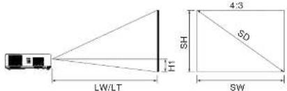
| PT-LB20NTU/PT-LB20U | LW=0.030xSD/0.0254-0.037 |
| LT=0.036xSD/0.0254-0.037 | |
| PT-LB20SU | LW=0.031xSD/0.0254-0.038 |
| LT=0.037xSD/0.0254-0.038 | |
| PT-LB20VU | LW=0.035xSD/0.0254-0.037 |
| LT=0.042xSD/0.0254-0.036 |
For 16:9 aspect ratios, the following formula can be used to calculate the projection distance.
| PT-LB20NTU/PT-LB20U | LW=0.032xSD/0.0254-0.037 |
| LT=0.039xSD/0.0254-0.037 | |
| PT-LB20SU | LW=0.033xSD/0.0254-0.038 |
| LT=0.040xSD/0.0254-0.038 | |
| PT-LB20VU | LW=0.038xSD/0.0254-0.037 |
| LT=0.046xSD/0.0254-0.037 |
*The values obtained from the formulas above are approximate.
Using the SERIAL connector
The serial connector which is on the connector panel of the projector conforms to the RS-232C interface specification, so that the projector can be controlled by a personal computer which is connected to this connector.
Connection
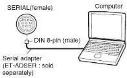
NOTE:
- You must use only RS-232C Serial Interface Cable with ferrite core, type ET-ADSER.
Pin assignments and signal names
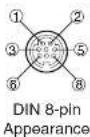
| Pln No. | Signal name | Contents |
| 3 | RXD Received data | |
| 4 | GND Earth | |
| 5 | TXD Transmitted data | |
| 1 | Connected internally | |
| 2 | ||
Communications settings
| Signal level RS-232C | |
| AsynchronousSync. metho | |
| Baud rate | 9 600 bps |
| Parity | None |
| Character length 8 bits | |
| Stop bit 1 bit | |
| X parameter None | |
| S parameter None | |
Basic format
The data sent from the computer to the projector is transmitted in the format shown below.
| STX | Command | : | Parameter | ETX |
| Start byte(02h) | 3 bytes | 1 byte | End byte(03h) | |
NOTE:
- The projector can not receive the command for 10 seconds after the lamp is switched on. Wait 10 seconds before sending the command.
- If sending multiple commands, check that a response has been received from the projector for one command before sending the next command.
- When a command which does not require parameters is sent, the colon (:) is not required.
Control commands
The commands which the personal computer can use to control the projector are shown in the following table.
| Command | Control Contents | Remarks |
| Power ONPON | In standby mode, all commands other than the PON command are ignored.The PON command is ignored during lamp ON control.If a PON command is received while the cooling fan is operating after the lamp has switched off, the lamp is not turned back on again straight away, in order to protect the lamp. | |
| Power OFFPOF | ||
| VolumeAVL | Parameter000-063 (Adjustment value 0-63) | |
| IIS | Input signal selection | ParameterVID=VIDEO SVD=S-VIDEORG1=RGB1 RG2=RGB2NWP=NETWORK (PT-LB20NTU only) |
| Q$S | Lamp ON condition query | Callback0 = Standby1 = Lamp ON control active2 = Lamp ON3 = Lamp OFF control active |
| Shutter functionOS | Operation will be switched between ON and OFF each time the command is sent. Do not switch operation ON and OFF after only short periods of time. |
Cable specifications
(When connected to a personal computer)
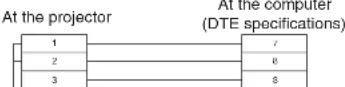

Dimensions
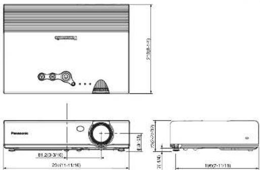
Trademark acknowledgements
• VGA and XGA are trademarks of International Business Machines Corporation.
● Macintosh is a registered trademark of Apple Computer, Inc.
- S-VGA is a registered trademark of the Video Electronics Standards Association.
All other trademarks are the property of the various trademark owners.
NOTES IMPORTANTES CONCERNANT LA SECURITE
AVERTISSEMENT: POUR REDUIRE LES RISQUES DE FEU OU DE CHOC ÉLECTRIQUE, NE PAS EXPOSER CE PRODUIT À L'EAU OU À L'HUMIDITÉ
ASPECTO, REDIMENSION,
BLOQU. CUADRO
TIEMPO LAMP, FUNC 1, TECLA
CTRL, AUTOAPAGADO, MEMESTADO
MEM.ESTADO
Comienzo
7 (NTSC/NTSC4.43/PAL/PAL-M/PAL-N/
PAL60/SECAM)
G.SYNC: 1,0 V [p-p], 75 Ω
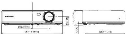
Professional/Industrial Video
Panasonic Broadcast & Television Systems Company
Unit of Panasonic Corporation of North America
One Panasonic Way 4E-7 Secaucus, NJ 07094 (201) 392-4443
3330 Cahuenga Blvd West Los Angels, CA 90068 (323) 436-3500
Technical Support:
(800) 524-1448
- Dear Panasonic Customer:
- IMPORTANT SAFETY NOTICE
- WARNING: TO REDUCE THE RISK OF FIRE OR ELECTRIC SHOCK, DO NOT EXPOSE THIS PRODUCT TO RAIN OR MOISTURE.
- CAUTION:
- WARNING:
- FCC RF Exposure Warning: (If provided with wireless device)
- Declaration of Conformity
- Contents
- Preparation
- Getting started
- Basic operation
- Useful functions
- Adjustments and settings
- Changing the display
- Setting up the security
- Care and maintenance
- Cleaning and replacing
- Others
- Precautions with regard to safety
- WARNING
- Caution
- NOTICE:
- Accessories
- Before use
- Caution when moving the projector
- Cautions regarding setting-up
- Notes on use
- In order to get the best picture quality
- Do not touch the surfaces of the lens with your bare hands.
- Screen
- Lamp
- Liquid crystal panel
- Location and function of each part
- NOTE:
- Setting-up
- Projection methods
- Connections
- Notes on connections
- Connecting to video equipment
- Preparation for the remote control unit
- Turning on the power
- ④ Press the input select button to select the input signal.
- ⑤ Adjusting the angle
- ⑥ Press the AUTO SETUP button to initiate automatic positioning.
- Direct power off function
- Correcting keystone distortion and automatic positioning (AUTO SETUP)
- Turning off the picture and sound momentarily (SHUTTER)
- Press the SHUTTER button.
- Pausing a picture (FREEZE)
- Press the FREEZE button.
- Enlarging the picture (D.ZOOM)
- Adjusting the volume (VOLUME)
- Displaying two screens (INDEX WINDOW)
- Press the INDEX WINDOW button.
- The remote control unit functions during INDEX WINDOW
- On-screen menus
- Menu screens
- POSITION menu (page 41)
- INDEX WINDOW function (page 31)
- SHUTTER function (page 29)
- LANGUAGE menu (page 44)
- OPTION menu (page 45)
- SECURITY menu (page 49)
- NETWORK menu (page 51) (PT-LB20NTU only)
- Menu operation guide
- ①Press the MENU button.
- ②Press the ▲ or ▼ button to select an item.
- ③Press the ENTER button to accept the
- Unavailable on-screen menu items
- Returning a setting to the factory default
- - When an individual adjustment screen is being displayed
- Correcting keystone distortion
- Adjusting the picture
- PICTURE MODE
- CONTRAST
- BRIGHT
- COLOR
- TINT
- SHARPNESS
- COLOR TEMP.
- White balance R/G/B (W-BAL R/G/B)
- DAYLIGHTVIEW
- AUTO
- ON
- OFF
- W-BAL
- [Unreadable]
- 六
- AI
- TV-SYSTEM
- STILL MODE
- SIGNAL MODE
- Projecting sRGB-compatible pictures
- Adjusting the position
- POSITION
- DOT CLOCK
- CLOCK PHASE
- ASPECT
- 4:3
- 16:9
- S4:3
- S1 video signals
- RESIZING
- FRAME LOCK
- Changing the display language
- Option settings
- OSD
- AUTO SEARCH
- AUTO SIGNAL
- AUTO KEYSTN
- RGB2 SELECT
- Noise Reduction (NR)
- BLACKBOARD
- DESK/CEILING
- DESK
- CEILING
- FAN CONTROL
- LAMP POWER
- LAMP RUNTIME
- FUNC 1
- DAYLIGHT
- KEYSTONE
- CONTROL KEY
- AUTO POW.OFF
- POWER MEMORY
- Setting up the security function
- INPUT PASSWD
- AMEND PASSWD
- TEXT DISPLAY
- TEXT CHANGE
- Network setup (PT-LB20NTU only)
- NETWORK
- NAME CHANGE
- WEB CONTROL
- STATUS
- DEFAULT
- When the TEMP indicator and the LAMP indicator are illuminated
- Cleaning and replacing the air filter
- Cleaning
- Replacement procedure
- Replacing the lamp unit
- Notes on replacing the lamp unit
- Lamp unit replacement period
- Lamp unit replacement procedure
- SELECT RETRN
- Before calling for service
- Cleaning and maintenance
- Specifications
- Connectors
- Appendix
- Projection dimensions calculation methods
- Using the SERIAL connector
- Basic format
- Control commands
- Cable specifications
- Trademark acknowledgements
- NOTES IMPORTANTES CONCERNANT LA SECURITE
Brand : PANASONIC
Model : PT-LB20NTU
Category : Video projector