
ProductionVIEW HD MV - Controller Vaddio - Free user manual and instructions
Find the device manual for free ProductionVIEW HD MV Vaddio in PDF.


| Product Type | Precision Camera Controller |
| Model | ProductionVIEW HD MV |
| Part Numbers | 999-5700-000 (North America), 999-5700-001 (International) |
| Number of Cameras Supported | Up to 7 PTZ cameras |
| Camera Control Ports | 7 discrete RS-232 ports on RJ-45 connectors (no daisy-chaining required) |
| Joystick | 3-axis programmable joystick for pan, tilt, and zoom control |
| Presets per Camera | 14 pan/tilt/zoom position presets (local or in-camera store) |
| Control Buses | Two discrete control buses (Control A and B) for camera selection and external device control |
| External Control | RS-232 DB-9 port for external controllers or switchers; tally outputs for external devices |
| Power Input | 18 VDC, 2.75 A (use only provided power supply) |
| LCD Display | Backlit 8-line LCD screen for menu navigation and real-time information |
| Focus Control | Large focus wheel with auto focus and fast focus functions |
| Iris and Gain Controls | Knobs for real-time iris and gain adjustment; auto iris and backlight compensation buttons |
| Color Controls | Red and blue gain knobs; one-push and auto white balance |
| Detail Control | Adjusts sharpness of camera output |
| Dual Link Mode | Allows two Precision Camera Controllers to be linked for expanded control |
| Compatible Cameras | Auto-detect for Sony, Canon, Panasonic; manual selection available |
| Menu Navigation | Up/down arrow buttons, select and cancel buttons for menu traversal |
| Camera Rescan | Scans ports 1-7 for connected cameras; configurable per port |
| RS-232 Control API | Command set for external programming (9600 bps, 8 data bits, no parity, 1 stop bit) |
Frequently Asked Questions - ProductionVIEW HD MV Vaddio
User questions about ProductionVIEW HD MV Vaddio
0 question about this device. Answer the ones you know or ask your own.
Ask a new question about this device
Download the instructions for your Controller in PDF format for free! Find your manual ProductionVIEW HD MV - Vaddio and take your electronic device back in hand. On this page are published all the documents necessary for the use of your device. ProductionVIEW HD MV by Vaddio.
USER MANUAL ProductionVIEW HD MV Vaddio
Installation and User Guide

PRODUCTIONVIEW™
PRECISION CAMERA CONTROLLER
Integration Joystick, with Seven Discrete Camera Control Ports, On-board Camera Presets, CCU Exposure and Color Control Functions with External Control Capability
Part Number: 999-5700-000 (North America) Part Number: 999-5700-001 (International)
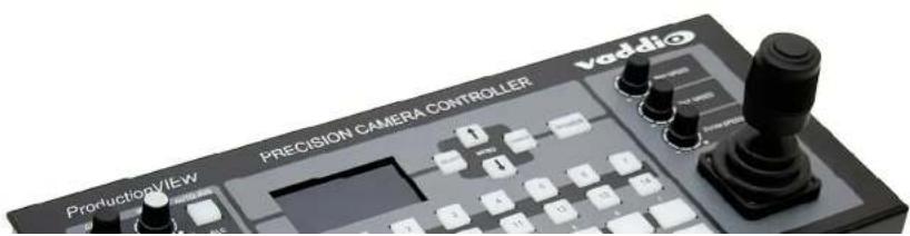
Table of Contents
Overview: 3
Unpacking: 3
Image: Front panel of ProductionVIEW Precision Camera Controller....4
Front Panel Controls: 4
Image: Rear Panel of ProductionVIEW Precision Camera Controller 5
Rear Panel I/O: 5
First Time Set-up with the ProductionVIEW Precision Camera Controller: 5
Drawings: System Configurations Examples....6
Operating the ProductionVIEW Precision Camera Controller: 7
ProductionVIEW PRECISION CAMERA CONTROLLER Menu Structure 8
Compliance and CE Declaration of Conformity 11
Warranty Information: 12
Appendix 1: 13
RS-232 Control 13
Communication Specification....13
Female DB-9 Control Port Pin-outs 13
Camera Control Ports 1 through 7 - RS-232 on RJ-45 Connectors: 13
Appendix 2: RS-232 Control 13
API and Programming Language....14
Appendix 2: Command Structure Definitions .... 15
General Specifications: 15
ProductionVIEW Precision Camera Controller
vaddio
OVERVIEW:
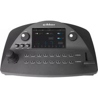
In our continuing drive to redefine camera control, Vaddio™ introduces the Precision Camera Controller system. Designed to control up to seven PTZ cameras, the Precision Camera Controller can be used as a stand-alone device or in conjunction with a variety of video switchers or mixers on the market today.
The control surface gives system users real-time knobs and buttons to control functions. In addition to a joystick controller with separate pan, tilt and zoom speed adjustment knobs, there are controls for red & blue gain, detail, iris and gain.

ProductionVIEW Precision Camera Controller
The system is capable of storing up to 14 pan, tilt and zoom position presets per camera. Two discrete control buses can be configured to select PTZ cameras, as well as control an external switcher or mixer via either RS-232 or tally outputs on the back of the console.
Precision Camera Controller is the ideal camera control system for a variety of applications, including houses of worship, local government, live event production and other situations where PTZ camera control is required.
Intended Use:
Before operating the device, please read the entire manual thoroughly. The system was designed, built and tested for use indoors, and with the provided power supply and cabling. The use of a power supply other than the one provided or outdoor operation has not been tested and could damage the device and/or create a potentially unsafe operating condition.
Important Safeguards:
Read and understand all instructions before using. Do not operate any device if it has been dropped or damaged. In this case, a Vaddio technician must examine the product before operating. To reduce the risk of electric shock, do not immerse in water or other liquids and avoid extremely humid conditions.

Use only the power supply provided with the system. Use of any unauthorized power supply will void any and all warranties.
Please do not use "pass-thru" type RJ-45 connectors. These pass-thru type connectors do not work well for professional installations and can be the cause of intermittent connections which
ProductionVIEW Precision Camera Controller
vaddio
Image: Front panel of ProductionVIEW Precision Camera Controller

Front Panel Controls:
- Iris and Gain Controls*: Iris and gain can be adjusted from knobs for real-time control of these critical functions. There are also buttons for auto iris and backlight compensation.
- Detail *: Detail adjusts the sharpness of the camera's output.
- Color Controls*: Red and blue gain allow adjust the color of the camera's image sensor. In addition there are both a one-push white balance and auto white balance.
- Focus Adjustments: A large focus wheel helps with accurate focusing. An auto focus button, and fast focus are located next to the focus wheel. Pressing Fast Focus once zooms the camera in all of the way, allowing the user to adjust the focus manually. Pressing Fast Focus again zooms the camera back out to the preset zoom position. NOTE: Focus controls can only be used with compatible cameras.
- Control A and B Buses: Selects which camera to control (PTZ, Iris, Color, Presets, etc.) on the Control A or
vaddio
Image: Rear Panel of ProductionVIEW Precision Camera Controller
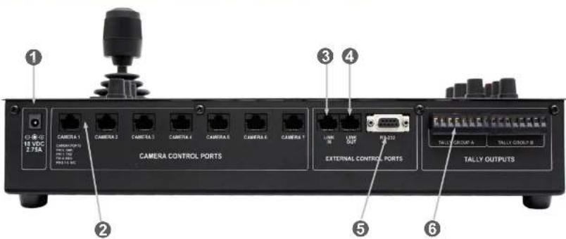
- Power Input: Use only the 18 VDC, 2.75A power supply provided with the Precision Camera Controller. Use of any other power supply may cause damage to the Precision Camera Controller and to the products connected to it.
- Camera Control Ports on RJ-45 connectors: One camera control port per camera (no daisy-chaining is required, or supported).
- Link In: This is a data input port set up to receive a connection from a Secondary Precision Camera Controller for Link function. Link allows a user to control all cameras connected to one or both controllers from a single position.
- Link Out: This is a data output port for setting up a Precision Camera Controller as a secondary Precision Camera Controller, when the cable is run to the Link In port on another Precision Camera Controller.
- RS-232 Control Port: DB-9 for RS-232 control of internal functions (Pin 2 = TX, Pin 3 = RX, Pin 5 = GND) for use with external controllers or external production switchers.
- Tally Outputs: For use with tally light or external devices (i.e. video switchers, camera control units, etc.). These external control contacts correspond directly to front panel Control A & B buses. Tally contacts are latching, TTL type. These triggers are not relays and no voltage should be applied to these triggers at any time. The triggers are configurable as Active High or Active Low.
ProductionVIEW Precision Camera Controller
vaddio
Drawings: System Configurations Examples
Sample Configuration 1:
Precision Camera Controller connected to seven (7) PTZ cameras (like Vaddio HD-20s) directly.

Precision Camera Controller
Sample Configuration 2:
Two Precision Camera Controllers set up in Link Mode. The Precision Camera Controller with the cameras connected is the Primary, and the Precision Camera Controller without cameras is the Secondary unit. There can be two operators, but only one operator can access the cameras at a time (Cessna 172 not included).

Sample Configuration 3:
Two Precision Camera Controllers set up in Link Mode. Each Precision Camera Controller has 7 cameras connected, and all cameras can be controlled from either Precision Camera Controller, however not concurrently. There can be two operators.
OPERATING THE PRODUCTIONVIEW PRECISION CAMERA CONTROLLER:
Most of the console functions and controls are easy and intuitive. However, there are some more involved procedures listed below.
Master Power Switch:
- When the Master Power Switch is powered down, all of the attached cameras will be placed in standby. To turn the system off, the button must be touched and held down for two (2) seconds (the delay in "off" command is to ensure that the system is not inadvertently turned of during an event).
- When the Master Power Switch is powered up, all attached cameras will activate and select default camera and preset information as defined in the menu. The Precision Camera Controller will scan the inputs for camera type and auto-configure accordingly. This can take up to one minute and is normal operation. Precision Camera Controller will also scan for, and confirm connectivity to an external switcher if it is configured for operation with an external switcher via RS-232.
Important Note: When the camera control ports are changed or reconfigured, RESCAN CAMERAS in the menu must be selected, or the Precision Camera Controller must be rebooted.
Setting-up Compatible External Switchers using RS-232:
The RS-232 control codes for the Edirol V-44SW and Isis external switchers are built into the Precision Camera Controller. To activate these codes, use the following procedure:
- Go to the Menu (see page 10) under Video Switcher and select the desired switcher mode.
- The next item in the menu is the transition time. Set this to the desired time (for Edirol only).
- Turn off the ProductionVIEW Precision Camera Controller.
- Connect the external video switcher to the RS-232 Control Port (DB-9) on the back of the Precision Camera Controller.
- Turn on the external switcher and let it boot up completely.
- Turn on the Precision Camera Controller and let it boot up completely – making sure that it recognizes the external switcher (on the LCD screen of Precision Camera Controller).
- Test for proper operation
NOTE: If an external switcher is connected to Precision Camera Controller, you can't use the system in "Dual Link" mode, with two Precision Camera Controllers connected to each other (see configurations)
Setting Camera Presets per Channel:
- Press and hold the camera selection button for 4 seconds on the Control A (if A is the default) bus.
- The unused camera presets and camera selection button will flash at this time
ProductionVIEW Precision Camera Controller
vaddio
The 3-Axis Joystick:
Within the menus, the 3-axis joystick is programmable for pan, tilt and zoom direction control. The zoom-in/zoom-out, tilt-up/tilt-down and pan-left/pan-right commands can be inverted on all 3-axis to customize control of the PTZ cameras attached to Precision Camera Controller.
LCD Screen:
The LCD screen displays the menu structure, as well as information in real time as buttons are pressed, or buttons pushed on the controller.
Note: The LCD is covered with a thin protective film, please remove this film carefully.
ProductionVIEW PRECISION CAMERA CONTROLLER Menu Structure
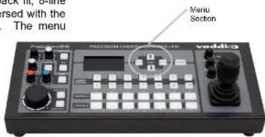
The ProductionVIEW Precision Camera Controller has a back lit, 8-line LCD that displays the system menus. The menus are traversed with the up and down arrows buttons, select and cancel buttons. The menu
structure is as follows:
1 ^st Screen
ProductionVIEW
PC
V01.00.0X (software version 0X)
Rescan
Cameras
Cam
Search Menu
Default
Camera
Default
Preset
Rescan Cameras
Select
Start - Rescans control ports 1 through 7 to find the cameras connected
Cam Search Menu
Select
All Ports: (select search method - Auto. Sony, Canon, Panasonic)
Port 01: (select search method - Auto, Sony, Canon, Panasonic)
Port 02: (select search method - Auto, Sony, Canon, Panasonic)
Port 03: (select search method - Auto, Sony, Canon, Panasonic)
Port 04: (select search method - Auto, Sony, Canon, Panasonic)
Port 05: (select search method - Auto, Sony, Canon, Panasonic)
Port 06: (select search method - Auto, Sony, Canon, Panasonic)
Port 07: (select search method - Auto, Sony, Canon, Panasonic)
NOTE: When using Panasonic cameras, it is necessary to select Panasonic to speed up the recognition of the cameras when ProductionVIEW HD is turned on.
Production VIEW Precision Camera Controller
vaddio
Pan Dir Menu (Pan Direction Menu)
>Select
| >All Ports: Normal or Invert (default is Normal) Inverts the Joystick Pan Direction (Inverted - left = right) | ||||
| >Port 01: Normal or Invert | ||||
| >Port 02: Normal or Invert | ||||
| >Port 03: Normal or Invert | ||||
| >Port 04: Normal or Invert | ||||
| >Port 05: Normal or Invert | ||||
| >Port 06: Normal or Invert | ||||
| >Port 07: Normal or Invert | ||||
| >Return to Main | ||||
| >Select | Returns | to | Main | Menu |
Tilt Dir Menu (Tilt Direction Menu)
>Select
| >All Ports: Normal or Invert (default is Normal) Inverts the Joystick Tilt: Direction (Inverted - up = down) | ||||
| >Port 01: Normal or Invert | ||||
| >Port 02: Normal or Invert | ||||
| >Port 03: Normal or Invert | ||||
| >Port 04: Normal or Invert | ||||
| >Port 05: Normal or Invert | ||||
| >Port 06: Normal or Invert | ||||
| >Port 07: Normal or Invert | ||||
| >Return to Main | ||||
| >Select | Returns | to | Main | Menu |
Zoom Direction
Normal or Invert (default is Normal)
Inverts the Joystick Zoom Direction (Inverted - Clockwise twist = zoom out)
Camera Select Bus
>Select
| > | Control | A |
| > | Control | B |
Assigns Control Bus A or B to select cameras for Pan/Tilt/Zoom control
Preset Pan Speed
>Select
01 - 24
Sets the Pan Speed on all cameras between camera presets (24 is fastest) (default is 18)
(This parameter does not affect the Pan Speed or sensitivity of the Joystick)
vaddio
System Menu (continued)
Serial Echo
Select
Y e s o r N o Turns Serial Echo on or off (default is Yes or On)
Serial Info
Select
Reports button pushes on front panel out the serial port (default is off) (Does not report joy stick position)
Panel Lights
Select
or Cancel
h 50
Panel Light Brightness (all lights - 50 is the brightest) (default is 25, off is 00)
Clear Memory
Select
Clear Presets
Select
S t a r t
Note: Clears only local presets in Precision Camera Controller, not in camera presets.
Power Up Preset
Select
Home Camera
Select - Upon power up, all cameras will go to their home position
Preset
Select - Upon power up, all cameras will go to Preset 14
Preset Location
Local
InCam 8 Local
In "Local" mode, the ProductionVIEW stores all 14 presets internally
In "6 InCam 8 Local" mode, the presets 1 through 6 will be stored in the cameras.
Presets 7 through 14 will be stored in the Precision Camera Controller.
Note: The "6 InCam 8 Local" mode allows for switching video sources when Sony cameras are moving to preset locations. Since Presets are stored in camera, the system does not have to wait for position feedback before allowing another command to be entered.
Dual Link
Select
. 0... 0
ProductionVIEW Precision Camera Controller

COMPLIANCE AND CE DECLARATION OF CONFORMITY
FCC Part 15 Compliance
This equipment has been tested and found to comply with the limits for a Class A digital device, pursuant to Part 15 of the FCC Rules. These limits are designed to provide reasonable protection against harmful interference when the equipment is operated in a commercial environment. This equipment generates, uses, and can radiate radio frequency energy and, if not installed and used in accordance with the instruction manual, may cause harmful interference to radio communications. Operation of this equipment in a residential area is likely to cause harmful interference in which case the user will be required to correct the interference at his/her own expense.
Operation is subject to the following two conditions: (1) This device may not cause interference, and (2) This device must accept any interference including interference that may cause undesired operation of the device.
Changes or modifications not expressly approved by Vaddio can affect emission compliance and could void the user's authority to operate this equipment.
ICES-003 Compliance
This digital apparatus does not exceed the Class A limits for radio noise emissions from digital apparatus set out in the Radio Interference Regulations of the Canadian Department of Communications.
This product has been evaluated for Electromagnetic Compatibility under the EN 55103-1/2 standards for Emissions and Immunity and meets the requirements for E4 - Controlled EMC Environment.
This product complies with Class A (E4 environment). In a domestic environment this product may cause radio interference in which case the user may be required to take adequate measures.
Standard(s) To Which Conformity Is Declared:
EMC Directive 2004/108/EC
EN 55103-1 Electromagnetic Compatibility - Emissions
EN 55103-2 Electromagnetic Compatibility - Immunity
EN 55022A Conducted and Radiated Emissions
FN 61000-3-2 Limits for Harmonic Current Emmissions
Production VIEW Precision Camera Controller
vaddio
WARRANTY INFORMATION:
(See Vaddio Warranty, Service and Return Policies posted on vaddio.com for complete details):
Hardware* Warranty: One year limited warranty on all parts. Vaddio warrants this product against defects in materials and workmanship for a period of one year from the day of purchase from Vaddio. If Vaddio receives notice of such defects during the warranty period, they will, at their option, repair or replace products that prove to be defective. Please see Vaddio's Service Terms and Conditions at vaddio.com for specific details and policies.
Exclusions: The above warranty shall not apply to defects resulting from: improper or inadequate maintenance by the customer, customer applied software or interfacing, unauthorized modifications or misuse, operation outside the normal environmental specifications for the product, use of the incorrect power supply, improper extension of the power supply cable or improper site operation and maintenance.
Vaddio Customer Service: Vaddio will test, repair, or replace the product or products without charge if the unit is under warranty and is found to be defective. If the product is out of warranty, Vaddio will test then repair the product or products. The cost of parts and labor charge will be estimated by a technician and confirmed by the customer prior to repair. All components must be returned for testing as a complete unit. Vaddio will not accept responsibility for shipment after it has left the premises.
Vaddio Technical Support: Vaddio technicians will determine and discuss with the customer the criteria for repair costs and/or replacement. Vaddio Technical Support can be contacted through one of the following resources: e-mail support at support@vaddio.com or online at www.vaddio.com.
Return Material Authorization (RMA) Number: Before returning a product for repair or replacement, request an RMA from Vaddio's technical support team. Provide a technician with a return phone number, e-mail address, shipping address, and product serial numbers and describe the reason for repairs or returns as well as the date of purchase and proof of purchase. Include your assigned RMA number in all correspondence with Vaddio. Write your assigned RMA number on the outside of the box when returning the product. All products returned for credit are subject to a restocking charge without exception.
Voided Warranty: The warranty does not apply if the original serial number has been removed or if the product has been disassembled or damaged through misuse, accident, modifications, or unauthorized repair. Cutting the power supply cable on the secondary side (low voltage side) to extend the power to the device (camera or controller) voids the warranty for that device.
Shipping and Handling: Vaddio will not pay for inbound shipping transportation or insurance charges or accept any responsibility for laws and ordinances from inbound transit. Vaddio will pay for outbound shipping, transportation, and insurance charges for all items under warranty but will not assume responsibility for loss and/or damage by the outbound freight carrier. • If the return shipment appears damaged, retain the original boxes and packing material for inspection by the carrier. Contact your carrier immediately.
Products Not Under Warranty: Payment arrangements are required before outbound shipment for all out of warranty products.
*Vaddio manufactures its hardware products from parts and components that are new or equivalent to new in accordance with industry standard practices.
vaddio
APPENDIX 1:
RS-232 Control
The ProductionVIEW PRECISION CAMERA CONTROLLER has six (7) discrete camera control ports which eliminates the need for daisy-chaining control cabling. With both the ProductionVIEW and ProductionVIEW PRECISION CAMERA CONTROLLER, all cabling configurations are home-run type or "star" wiring configurations. Each Channel will auto-configure the input channel for video signal and control for the camera attached.
Vaddio uses very simple control protocols to accomplish custom programming with the ProductionVIEW and ProductionVIEW PRECISION CAMERA CONTROLLER. The Communication Specification, API and Programming Language are listed below and definitions are listed on the next page thereafter.
Communication Specification
Communication Speed: 9600 bps (default)
Start bit: 1
Stop bit: 1
Data bits: 8
Parity: None
Female DB-9 Control Port Pin-outs
Pin 2: TXD
Pin 3: RXD
Pin 5: GND
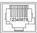
Camera Control Ports 1 through 7 - RS-232 on RJ-45 Connectors:
PIN# Signal
1) Unused
2) Unused
3) Unused
4) Unused
5) Unused
6) GND
7) TXD (to RXD of camera)
8) RXD (from TXD of camera)
API and Programming Language
(Firmware Version V01.01.XX)
| Vaddic ProductionVIEW Precision Camera Controller | |||
| ? - This Menu | |||
| System Access | |||
| Power x- Power(On/Off) | |||
| InCtrlA x- Control A (1-7) | InCtrl8 x- Control B (1-7) | ||
| Camera x- Switch to Camera(1-7) | AMB x- AutoWhiteBal(On,Off) | ||
| Preset x- Go to Preset(1-14) | BLC x-BacklightComp(On,Off) | ||
| Store x- Store Preset(1-14) | Rescan - Rescan cameras | ||
| Joystick Pan, Tilt, Zoom | |||
| JPanDir x,x-Port(0-7) Invert/Normal | JPanSpd x,x-Port(0-7),Spd(1-24) | ||
| JTiltDir x,x Port(0 7) Invert/Normal | JTiltSpd x,x Port(0-7),Spd(1 20) | ||
| JZoomDir x,x Port(0 7) Invert/Normal | JZoomSpd x,x Port(0-7),Spd(0 7) | ||
| Preset Pan, Tilt, Zoom | |||
| Panspeed x- Preset Pan Speed (1-24) | TiltSpeed x-Preset Tilt Spd(1-20) | ||
| ZoomSpeed x- Preset Zoom Spd (0-7) | Home - Home Camera | ||
| PreselLoc x- Store Preset (InCam/Lcl) | OnCamInit x- (Home/Preset14) | ||
| Camera | |||
| Move x,x- (Up/Down/Stop/Left/Right),Value | |||
| Zoom x,x- (In/Out/Stop),Value | |||
| Iris x,x- (Up/Down/Auto/Manual),Value | |||
| Focus x,x- (Up/Down/Auto/Manual),Value | |||
| System Setup and Utilities | |||
| SetDefault x- Set Default Preset(1-14) | Tally - Idle Tally(Righ/Low) | ||
| DefaultCam x- Set Default Camera(1-7) | Reset - 'CPU'Reset | ||
| DspCams - List connected cameras | SerialEcho x- Echo Serial (On/Off) | ||
| Version - Firmware Version | SerialInfo x- Status (On/Off) | ||
| ClearAll - Clear all presets | Config - List Config Settings | ||
APPENDIX 2: COMMAND STRUCTURE DEFINITIONS
| Command Parameters Description | ||
| AWB AWB On/Off[cr] Auto White Balance On/Off | ||
| BLC BLC On/Off[cr] Backlight Compensation On/Off | ||
| Camera Camera [9](cr) Select indicated camera (1-7) | ||
| ClearAll ClearAll[cr] Clear all presets | ||
| Config Config(cr) Display system configuration | ||
| DefaultCam DefaultCam [9](cr) Set default camera (1-7) | ||
| DispCams | DispCams(cr) | Display cameras connected(and Port) |
| Focus | Focus Up/Dn/AutoManual,[9] (cr) | Focus Up/Dn/AutoManual, Value |
| Home | Home(cr) | Home Camera |
| InClA | InClA [9] (cr) | Control A Bus buttons |
| InClB | InClB [9] (cr) | Control B Bus buttons |
| Iris | Iris Up/Dn/AutoManual,[8] (cr) | Iris change Up/Dn/AutoManual, Value |
| JPanDir JPanDir [9],[9](cr) Set Pan Direction by Port(0,1-7), Dir(Normal/Invert) | ||
| JPanSpd | JPanSpeed [9],[9](cr) | Set Pan Speed by Port (0,1-7), Speed(1-24) |
| JTitDir | JTitDir [9],[9](cr) | Set Tilt Direction by Port(0,1-7), Dir(Normal/Invert) |
| JTitSpd | JTitSpeed [9],[9](cr) | Set Tilt Speed by Port(0,1-7), Speed(1-20) |
| JZoomDir | JZoomDir [9],[8](cr) | Set Zoom Direction by Port(0,1-7), Dir(Normal/Invert) |
| JZoomSpd | JZoomSpeed [9],[9](cr) | Set Zoom Speed by Port(0,1-7), Speed(0-7) |
| Move | Move(Up/Down/Left/Right/Stop)(cr) | Move camera |
| OnCamInit | OnCamInit Home/Preset12(cr) | Set initialization preset Home camera or content of preset12 |
| PanSpeed | PanSpeed [9](cr) | Set Preset Pan Speed |
| Power | Power On/Off(cr) | Power system On/Off |
| Preset Preset [9] (cr) Recalling a stored preset | ||
| PresetLoc | PresetLoc[Local/InCam] (cr) | Set Preset location 6 in cam 8 in system, All in system |
| Rescan | Rescan(cr) | Initiate Camera scan |
| Reset | Reset(cr) | Soft System reset |
| SerialEcho | SerialEcho On/Off(cr) | Serial Echo On/Off |
| SerialInfo | SerialInfo(On/Off)(cr) | Serial Information mode on/off |
| SetDefault | SetDefault [9](cr) | Set default Preset (1-12) |
| Store | Store [9](cr) | Store indicated preset on the current camera(1-12) |
| Talty | Talty High/Low(cr) | Non-selected(Idle) tally level |
| TiltSpeed | TiltSpeed [9](cr) | Set Preset Tilt Speed |
| Version | Version(cr) | Display System Version information |
| Zoom | Zoom (in/Out/Slop)(cr) | Zoom Camera |
| ZoomSpeed | Set Preset Zoom Speed | |
GENERAL SPECIFICATIONS:

- PRODUCTIONVIEW™
- PRECISION CAMERA CONTROLLER
- Table of Contents
- vaddio
- OVERVIEW:
- Intended Use:
- Important Safeguards:
- Front Panel Controls:
- Drawings: System Configurations Examples
- Sample Configuration 1:
- Sample Configuration 2:
- Sample Configuration 3:
- OPERATING THE PRODUCTIONVIEW PRECISION CAMERA CONTROLLER:
- Master Power Switch:
- Setting-up Compatible External Switchers using RS-232:
- Setting Camera Presets per Channel:
- The 3-Axis Joystick:
- LCD Screen:
- ProductionVIEW PRECISION CAMERA CONTROLLER Menu Structure
- Cam Search Menu
- Pan Dir Menu (Pan Direction Menu)
- >Select
- Tilt Dir Menu (Tilt Direction Menu)
- Zoom Direction
- Camera Select Bus
- Preset Pan Speed
- FCC Part 15 Compliance
- ICES-003 Compliance
- Standard(s) To Which Conformity Is Declared:
- WARRANTY INFORMATION:
- APPENDIX 1:
- RS-232 Control
- Communication Specification
- PIN# Signal
- API and Programming Language
Brand : Vaddio
Model : ProductionVIEW HD MV
Category : Controller