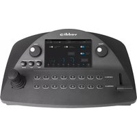
PCC MatrixMIX - Controller Vaddio - Free user manual and instructions
Find the device manual for free PCC MatrixMIX Vaddio in PDF.


| Product Type | Live Production Controller |
| Brand | Vaddio |
| Model | PCC MatrixMIX |
| Power Supply | PoE+ (Power over Ethernet) |
| Main Functions | Intuitive control for AV Bridge MatrixMIX switchers; touch-panel interface for CCU, presets, PIP, keying, audio, macros, streaming; T-bar for video transitions; three-axis Hall effect joystick; pan, tilt, zoom speed controls; focus knob; menu knob |
| Camera Control | Compatible with Vaddio RoboSHOT, ConferenceSHOT, ClearVIEW, PowerVIEW, ZoomSHOT, WideSHOT; select Sony and Panasonic models |
| Interface | Touch-panel display, illuminated pushbuttons, web interface for administrative control |
| Operating Temperature | 0°C to 40°C (32°F to 104°F) |
| Storage Temperature | 0°C to 40°C (32°F to 104°F) |
| Care Instructions | Wipe with clean, soft cloth; do not use abrasive chemicals; keep away from food and liquids |
| Compliance | FCC Part 15 Class A, ICES-003 Class A, EMC Directive 2004/108/EC, EN 55032, EN 55024, Safety IEC 60950-1, EN 60950-1 |
| Warranty | Two (2) year limited warranty on parts and labor for Vaddio manufactured products |
Frequently Asked Questions - PCC MatrixMIX Vaddio
User questions about PCC MatrixMIX Vaddio
0 question about this device. Answer the ones you know or ask your own.
Ask a new question about this device
Download the instructions for your Controller in PDF format for free! Find your manual PCC MatrixMIX - Vaddio and take your electronic device back in hand. On this page are published all the documents necessary for the use of your device. PCC MatrixMIX by Vaddio.
USER MANUAL PCC MatrixMIX Vaddio
natural_image
Black Vaddio control console with digital display and keypad (no visible text or symbols)Operator's Guide for the
PCC MatrixMIX
Live Production Controller
Document 411-0007-33 Rev A
August 2017
Contents
Overview 1.
About this Guide.1....
Features 1
Product Compatibility.2....
Switchers 2....
Vaddio Cameras.2
Non-Vaddio Cameras 2
A Quick Look at the Camera Controller 3....
Touch-Panel Display.3....
Focus Knob.... 3
Menu Knob.... 3
Pan, Tilt, and Zoom Speed Controls 3
Camera Select Buttons.... 4
T-Bar 4
Joystick 4
Operating the Controller 5....
Before You Start 5....
Touch-Panel Display Cheat Sheet 6
Safety Mute.... 6
Controller Adjustments.... 7
Selecting a Switcher from the Directory.... 8
Selecting Stream Sources.... 10
Setting Video Transition Speed.... 11
Defining Camera Presets 12
Working with Lighting and Color Settings.... 14
Selecting Lighting and Color Settings.... 14
Adjusting Lighting and Color (CCU) Settings 15
Saving Lighting and Color Adjustments.... 17
Working with Audio.... 18
Working with On-Screen Graphics 18
Selecting a PIP Source and Layout 20
Using Macros.... 21
Changing the Switching Mode 22
Changing to Low-Power Mode (Standby) 22
Troubleshooting....23
Operation, Storage, and Care 23
Compliance Statements and Declarations of Conformity 24
FCC Part 15 Compliance.... 24
ICES-003 Compliance 24
European Compliance 25
Warranty Information 26
Photo Credits 27
Index 28
Overview
This guide provides information about the PCC MatrixMIX live production controller:
■ 999-5755-000 – North America
■ 999-5755-001 – Europe and UK
■ 999-5755-009 – Australia and New Zealand
About this Guide
This guide covers:
■ The controller's physical features
■ Console operation
■ Basic troubleshooting

natural_image
Front view of a black audio recording device with control panel and display (no visible text or symbols)It does not include installation or system administration and setup. For complete product information, see the Integrator's Complete Guide to the PCC MatrixMIX Live Production Controller, which includes unpacking and installation, system administration, configuration, and technical specifications.
Features
Intuitive control for AV Bridge MatrixMIX switchers:
■ Touch-panel interface for CCU, presets, PIP, keying, audio control, macros, and streaming operation
■ T-bar control for video transitions
■ Web interface for complete administrative control from anywhere, using your browser
Precision for the most demanding camera operation environments:
■ Three-axis Hall effect joystick
■ T-bar for manual transitions
■ Pan, tilt, and zoom speed control knobs
■ Illuminated pushbuttons for camera selection
■ Large knobs for fine focus control and menu navigation, with push-to-select function
Versatile power solution using PoE+ (Power over Ethernet)
Product Compatibility
The PCC MatrixMIX is compatible with the following products.
Switchers
AV Bridge MatrixMIX
Vaddio Cameras
May require an update to the camera's firmware.
■ RoboSHOT Series(may use Quick-Connect or OneLINK device)
■ ConferenceSHOT Series*
■ ClearVIEW HD 20SE
■ PowerVIEW HD 22/30
■ ZoomSHOT 20
■ WideSHOT
* Includes cameras marked ClearSHOT 10 USB.
Non-Vaddio Cameras
■ Sony BRC Z330, Z700, H700, H900
■ Sony EVI-H100S
■ Sony SRG 120, SRG 300
■ Panasonic AW-HE 40, AW-HE 130
A Quick Look at the Camera Controller
The console provides quick, intuitive control of cameras and switcher functions.

natural_image
Front view of a black Vaddig audio recording device with control knobs and a digital display (no visible text or symbols)Touch-Panel Display
Access to:
■ Directory, for switcher selection
■ Camera presets, scenes, and CCU settings
■ Graphics keying and PIP
■ Audio
■ Macro recall
■ Streaming sources
■ Network information for the controller
■ One-touch standby (controller and selected cameras)
Focus Knob
Switch between modes - auto-focus (illuminated blue) or manual (illuminated red). Adjusts the focus when in manual mode.
Menu Knob
Navigate and select items from touch-panel screens and menus, adjust and save settings.
Pan, Tilt, and Zoom Speed Controls
The three speed control knobs above the joystick adjust the selected camera's speeds for pan, tilt, and zoom. When you adjust any of these knobs, the touch-panel displays a slider to show the speed range.
Camera Select Buttons
The buttons on the Program and Preview rows are associated with the same video sources. During normal operation, the buttons are illuminated if they are mapped to cameras or other video sources. Color indications:
■ Red – Current program output
■ Green – Current preview output
■ Blue – Available video source
- Blinking blue – No video source is currently available at the mapped IP address, or further configuration is required.
Button behavior depends on the selected switching mode.
A/B switching mode: One program output. The tally (red) indication is always on the Program row of buttons, and the preview indication is always on the Preview row.
Dual-bus switching mode: Two simultaneous program outputs. The buttons on the Program row show the tally for one output; the buttons on the Preview row show tally for the other output. Press another button to select a preview source. The button turns green to indicate that it will be the next source on that bus after a video transition (T-bar on the controller, or Take button on the multiviewer).
T-Bar
Manual control for video source transitions.
Joystick
Intuitive control for moving the selected camera to the desired position – left/right to pan, forward/back to tilt. Twist the joystick clockwise or counterclockwise to zoom the camera. Press the center button to return the camera to its home position.
The camera controller's web interface allows you to set normal or inverted directional operation, according to the operator's preference. See Configuring Joystick Behavior.
Operating the Controller
The PCC MatrixMIX live production controller is the preferred operator interface for the AV Bridge MatrixMIX multipurpose AV switcher. We recommend using it with the TeleTouch 27 USB multiviewer if it is sited with the switcher.
This chapter covers operation of the controller console. Some of these tasks can also be done in other ways – from the TeleTouch 27 USB multiviewer, or from the switcher's web interface.
To select a touch-panel control, do one of these things:
■ Tap the control on the touch-panel
■ Dial to the control using the Menu knob, then press the knob to select the control.
You can change some adjustments, such as audio volume sliders, directly on the touch-panel. To adjust controls that use arcs, such as the touch-panel brightness adjustment, you must use the Menu knob to make the adjustment, and then press the knob to save the change.
Before You Start
You will need additional information and software to control the cameras, other video sources, and audio equipment on your network.
■ The PCC MatrixMIX can control up to 10 switchers, which must be added to the controller's directory via the web interface; the admin login is required.
- You will need to view the switcher's multiview output. If you are not using a TeleTouch 27 USB multiviewer (for example, if operating the switcher remotely), you will need to view the multiviewer output as an IP stream.
■ To view the IP stream, the switcher must be configured to enable IP streaming.
■ To view the IP stream, you will need a stream viewer application such as VLC Media Player.
- You will need to know the streaming URL for each switcher's IP stream. This information is available on the Streaming page of each switcher's web interface; the admin login is required.
- When viewing the multiviewer stream, keep in mind that the stream will lag perceptibly – there is network-dependent latency in addition to 400 ms of inherent latency.
Touch-Panel Display Cheat Sheet
Where to find the controls you need right now.
| What do you need to do? Go to this screen | |
| Mute all video and audio outputs Safety Mute | (all screens) |
| View the controller's IP address and other network information | Settings: Info |
| Connect to a specific switcher to control its cameras | Directory |
| Store or recall presets for the selected camera Presets | |
| Select a defined set of lighting and color adjustments (recs) CCU scene) for the selected camera | Stenes |
| Adjust color and lighting settings for the selected camera | CCU |
| Store color and lighting adjustments as a CCU scene for selected camera | CU: Store as scene |
| View or change audio settings Audio | |
| Work with on-screen graphics Keying | |
| Select the source and placement for the picture-in-picture | (PIP) PIP |
| Work with macros | Macros |
| View or select streaming sources | Streaming |
| Adjust the touch-panel's brightness | Settings: Device |
| Put the system into standby mode; configure standby beh | havior Settings: Device |
Safety Mute
ALL SCREENS
In situations where it is desirable to mute all outputs together, select Safety Mute. This control is present at the top of every screen.
When you unmute Safety Mute, all inputs and outputs return to their previous states. For example, if the Program audio outputs were muted before Safety Mute was selected, they will remain muted after Safety Mute is deselected.

Controller Adjustments
SETTINGS SCREEN, DEVICE TAB
You can adjust the PCC MatrixMIX live production controller to suit the way you work.
To adjust the touch-panel brightness:
- Tap the Brightness arc, or dial to it using the Menu knob and then press the knob.
- Dial the Menu knob to adjust the brightness, then press the knob to save your change.
To set joystick direction:
Use the Invert Joystick controls to make the cameras pan and tilt in the direction you prefer for a given joystick movement.

Selecting a Switcher from the Directory
The controller must connect to a switcher to control the equipment connected to it. The top part of the touch-panel displays the name of the selected switcher (if any). You will also need a way to view the switcher's multiviewer output. The TeleTouch 27 USB multiviewer is recommended; however, for remote operation you can view the multiviewer output as a stream.
Note
A switcher may be in more than one controller's directory, and may be controlled in other ways more than one operator has control of a switcher, unexpected behavior may result.
With a TeleTouch 27 USB multiviewer:
On the Directory screen, tap the Connect button associated with the switcher if its status is Disconnected.
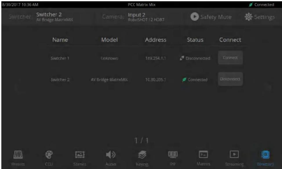
Without a multiviewer:
- On the Directory screen, select the Connect button associated with the switcher.
- On the Streaming screen, select Multiviewer as the IP streaming source if necessary.

- Open an instance of your stream viewer and point it at the URL for the desired switcher's IP stream.

Selecting Stream Sources
STREAMING SCREEN
By default, the connected switcher's Program output is the source for both the IP stream and the USB stream.
Select the desired source for each stream.
Note
If the source selections are dimmed for a stream, that stream is not enabled on the connected Enabling the stream requires administrative access to the switcher's web interface.

Setting Video Transition Speed
SETTINGS SCREEN, TRANSITIONS TAB
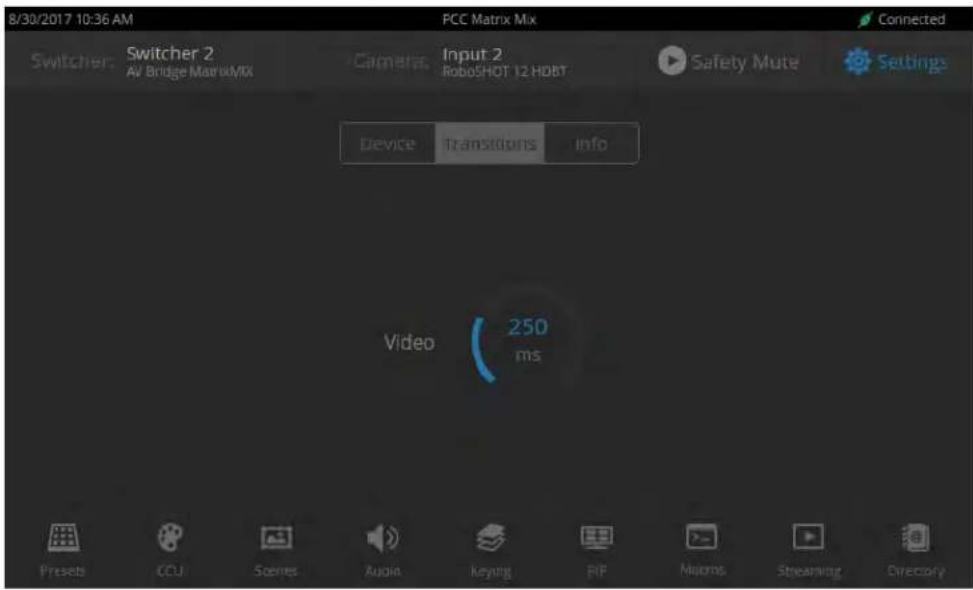
For automated video transitions (takes) using the Take button, the default transition time is 250 ms.
To view or change the transition time:
- Select Settings and go to the Transitions tab.
-
Tap the Video arc, then turn the Menu knob to the desired value.
-
Press the Menu knob to save the new setting.
Defining Camera Presets
PRESETS SCREEN (TOUCH-PANEL)
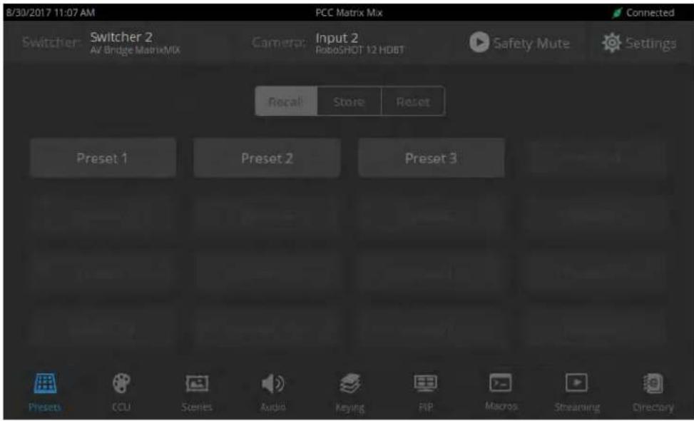
Like joystick control, preset operations affect the preview camera.
The camera controller does not store presets internally. It accesses the presets stored in the currently selected camera, and can write presets to the camera.
To store a new preset to the preview camera:
-
Set up the shot, including all adjustments.
-
If you are not changing an existing preset, make a note of which presets have already been stored. This information is on the Recall tab, which opens when you navigate to the Presets screen.
-
Select Store. All presets are available.

-
Select the preset to assign. If you choose a preset that is already assigned, you will overwrite the existing preset when you save the new one.
-
Select the preset options you want. Note that preset options depend on the camera's capabilities.
-
Select Store.

When you return to the Recall Preset screen, the new preset is available.
Working with Lighting and Color Settings
The camera controller gives you access to the selected camera's defined lighting and color settings (scenes) and its lighting and color (CCU) adjustments. You don't need to access each camera's web interface separately to adjust for consistent video.
Selecting Lighting and Color Settings
SCENES SCREEN (TOUCH-PANEL)
If the lighting or color balance doesn't look right in the video from the selected camera, go to the Scenes screen and choose the appropriate lighting setting. These are good starting points if you are not experienced with lighting and camera painting/shading.

If none of the available scenes produce the desired results, you can create custom settings.
Adjusting Lighting and Color (CCU) Settings
CCU SCREEN (TOUCH-PANEL)
If none of the lighting selections on the Scenes screen produce the desired results, adjust the image using the controls on the CCU screen.
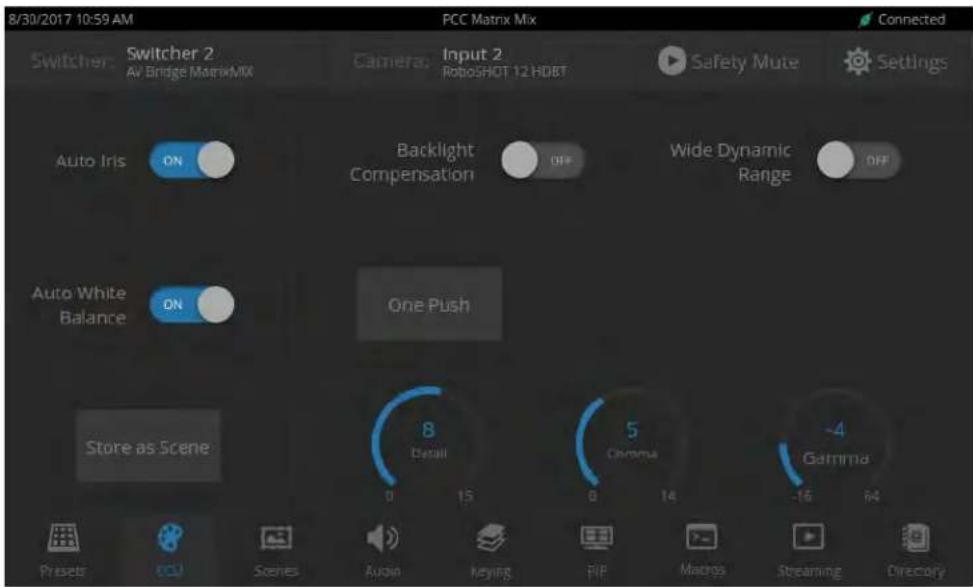
You may need to experiment to find the best combination of image adjustments.
Here are some tips.
| What do you need to correct? Change this: How: | ||||
| The image is too dark Iris Increase | (Reduce F-stop) | |||
| Iris Gain Increase | ||||
| The image looks washed out or faded Iris | Decrease | (Increase F-stop) | ||
| Iris Gain Decrease | ||||
| Chroma Increase | ||||
| Gamma Decrease | ||||
| The subject is silhouetted against a bright background | Backlight Compensation On | |||
| Colors look less vivid than they should Chroma Increase | ||||
| Colors look too vivid Chroma Decrease | ||||
| Highlights and shadows look right, but mid tones are too dark. | Gamma Increase | |||
| The mid-tones are too light. Enable Wide | Dynamic Range (WDR) if the camera supports this | |||
| Gamma Decrease | ||||
| The image looks grainy Detail | Decrease | |||
| Iris Gain Decrease | ||||
| "Soft focus" effect; the image looks unrealistically smooth | Detail | Increase | ||
| Colors look wrong; white objects do not a white | After | On | ||
| One Push | (tap) | |||
| Red Gain (less red/less green) | Dial down/up | |||
| Blue gain (less blue/less yellow) | Dial down/up | |||
| Too much red | Not enough red | Too much blue | Not enough blue | Balanced |
 |  | 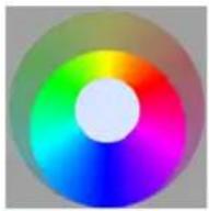 | 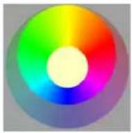 | 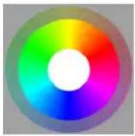 |
If you are adjusting for lighting conditions that are likely to recur, you can save your adjustments as a custom scene.
Saving Lighting and Color Adjustments
CCU SCREEN (TOUCH-PANEL)
When the lighting and color look good, select Store as Scene to save the adjustments. The screen prompts you to store the scene as Custom A, Custom B, or Custom C.

After you store the scene, it is available on the Scenes screen.

Working with Audio
AUDIO SCREEN (TOUCH-PANEL)
Up to four audio channels may be available on the Audio screen. Each provides a mute/unmute button, volume read-out, and volume slider control.
The audio channels available on the Audio screen depend on how the connected switcher is configured. Changing this requires administrative access to the switcher's web interface.

Working with On-Screen Graphics
KEYING SCREEN
Select the output to work with - Preview or Program.
To add or remove an existing graphic, select or deselect the Layer button associated with it.

To associate a graphic with a layer:
-
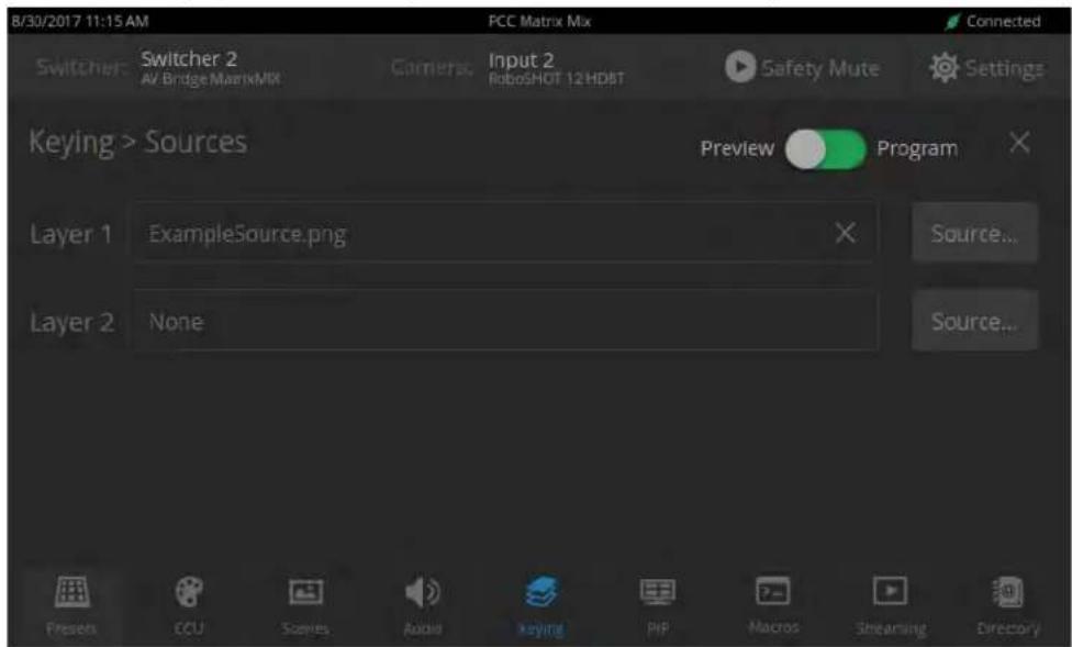
Select Sources. The Keying > Sources screen displays the filename of the graphic (if any) associated with each layer.
-
To delete a graphic from a layer, select the X to the right of the filename.
-
To add a graphic or change the graphic associated with a layer, select the Source button associated with the layer. This displays the library of available graphics files and sources.
-
Optional: Select one of the file search filters to display only the graphics of the desired mask type or source. If there are more graphics files and sources than will fit on the screen, the left and right navigation arrows become active.
-
Select the desired graphics file or source. This takes you back to the Keying > Sources screen.
-
Select the X in the upper right corner to return to the main Keying screen.

Selecting a PIP Source and Layout
PIP SCREEN
-
Select the output to work with - Preview or Program.
-
Select the camera or other video source to use as the PIP source.

-
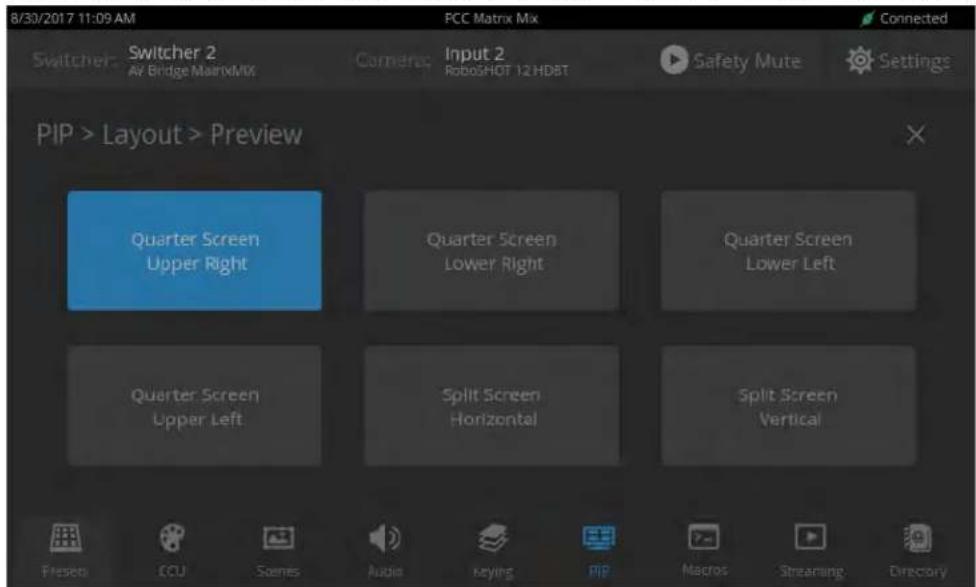
Select Layout to open the layout selection box.
-
Select the desired screen layout.
-
Select the X in the upper right corner to return to the PIP source selection screen.
Using Macros
MACROS SCREEN
Macros are defined in the switcher's administrative interface. Some may be specific to connected equipment rather than outputs.
Select the desired macro. Allow time for the macro to complete before starting another action.
Note
Some macros enforce a delay to allow time for completion. The delay can be a minute or more cases.

Changing the Switching Mode
SETTINGS SCREEN, DEVICE TAB
On the Device tab of the Settings screen, select the desired switcher mode - A/B or Dual Bus.

After changing from A/B switching to dual-bus mode or vice-versa, the controller(s) associated with the switcher may need to be rebooted.
Changing to Low-Power Mode (Standby)
SETTINGS SCREEN, DEVICE TAB
Note
On the Device tab of the Settings screen, select Standby. You may get a confirmation prompt. When the controller is in standby, you can tap the touch-panel to return to normal operation.
Troubleshooting
If the equipment does not behave as you expect, you may need to contact the system administrator for help. Use this table to determine whether it's something you can correct on your own.
| What is it doing? Possible causes Check and correct | ||
| Unable to log in successfully. | The web interface is out of sync with the unit. This can happen if more than one person is controlling the unit. | Use the browser's page refresh button. |
| The password has been changed. | Contact your system administrator. | |
| Unable to access the switcher's stream. | Streaming is not enabled on switcher. | Itbg in to the switcher's web interface as admin and enable the appropriate stream. |
| The program and preview indicators are blinking. (This may be visible on the switch as well.) | A take is in progress. If the indicators keep blinking but take occurs, the T-bar is not either end of its travel. | Complete the take. Be sure the T-bar is at the end of its travel. |
| The connected switcher is behaving in unexpected ways | More than one operator has control of the switcher. | |
| No audio or video from the selected switcher; multiview display is blank. | Safety Mute is on. Deselect mode. | Safety Mute on the PCC MatrixMIX touch-panel. |
| Safety Mute is on and cannot be deselected. | The switcher is in standby mode. | Deselect standby mode on the switcher. |
| No video from any source, by audio is present. | Video Mute is on at the switcher. | In the switcher's web interface, deselect Video Mute. |
| No audio, but video is present. | Audio Mute is on at the switcher. | In the switcher's web interface, deselect Audio Mute. |
Operation, Storage, and Care
For smears or smudges on the product, wipe with a clean, soft cloth. Do not use any abrasive chemicals. Keep this device away from food and liquids.
Do not operate or store the device under any of the following conditions:
■ Temperatures above 40^ C ( 104^ F) or below 0^ C ( 32^ F)
■ High humidity, condensing or wet environments
■ Inclement weather
■ Severe vibration
■ Dry environments with an excess of static discharge
Do not attempt to take this product apart. There are no user-serviceable components inside.
Compliance Statements and Declarations of Conformity
Compliance testing was performed to the following regulations:
| FCC Part 15 (15.107, 15.109), Subpart B Class A | |
| ICES-003, Issue 54: 2012 Class A | |
| EMC Directive 2004/108/EC Class A | |
| EN 55032: 2015 Class A | |
| EN 55024: November 2010 Class A | |
| KN22 2008 (CISPR 22: 2006) Class A | |
| KN24 2008 (CISPR 24: 1997 + A1: 2000 + A2: 2002) Class A | |
| IEC 60950-1:2005 (2nd Edition); Am 1: 2009 + Am 2: 2013 Safety | |
| EN 60950-1: 2006 + A11: 2009 + A1: 2010 + A12: 2011 + A2: 2013 Safety |
FCC Part 15 Compliance
This equipment has been tested and found to comply with the limits for a Class A digital device, pursuant to Part 15, Subpart B, of the FCC Rules. These limits are designed to provide reasonable protection against harmful interference when the equipment is operated in a commercial environment. This equipment generates, uses, and can radiate radio frequency energy and, if not installed and used in accordance with the instruction manual, may cause harmful interference to radio communications. Operation of this equipment in a residential area is likely to cause harmful interference in which case the user will be required to correct the interference at his/her own expense.
Operation is subject to the following two conditions: (1) This device may not cause interference, and (2) This device must accept any interference including interference may cause undesired operation of the device.

Changes or modifications not expressly approved by Vaddio can affect emission compliance and could void the user's authority to operate this equipment.
ICES-003 Compliance
This digital apparatus does not exceed the Class A limits for radio noise emissions from digital apparatus set out in the Radio Interference Regulations of the Canadian Department of Communications.
This product has been evaluated for Electromagnetic Compatibility under the EMC Directive for Emissions and Immunity and meets the requirements for a Class A digital device. In a domestic environment this product may cause radio interference in which case the user may be required to take adequate measures.
Standard(s) To Which Conformity Is Declared:

EMC Directive 2004/108/EC
EN 55022: December 2010 Conducted and Radiated Emissions
EN 55024: November 2010 Immunity
EN 61000-4-2: 1995 + Amendments A1: 1998 + A2: 2001 Electrostatic Discharge
EN 61000-4-3: 2006 + A1: 2008 Radiated Immunity
EN 61000-4-4: 2004 + Corrigendum 2006 Electrical Fast Transients
EN 61000-4-5: 2006 Surge Immunity
EN 61000-4-6: 2009 Conducted Immunity
EN 61000-4-8: 2010 Power Frequency Magnetic Field
EN 61000-4-11: 2004
Voltage Dips, Interrupts and
Fluctuations
KN22 2008 (CISPR 22: 2006) Conducted and Radiated Emissions
KN24 2008 (CISPR 24: 1997 + A1: 2000 + A2: 2002) IT Immunity Characteristics
EN 61000-4-2 Electrostatic Discharge
EN 61000-4-3 Radiated Immunity
EN 61000-4-4 Electrical Fast Transients
EN 61000-4-5 Surge Immunity
EN 61000-4-6 Conducted Immunity
EN 61000-4-8 Power Frequency Magnetic Field
EN 61000-4-11
Voltage Dips, Interrupts and
Fluctuations
IEC 60950-1: 2005 (2nd Edition); Am 1: 2009 + Am 2: 2013
Safety
EN 60950-1: 2006 + A11: 2009 + A1: 2010 + A12: 2011 + A2:
Safety
2013
Warranty Information
See Vaddio Warranty, Service and Return Policies posted on support.vaddio.com for complete details.
Hardware* warranty: Two (2) year limited warranty on all parts and labor for Vaddio manufactured products. Vaddio warrants its manufactured products against defects in materials and workmanship for a period of two years from the day of purchase, to the original purchaser, if Vaddio receives notice of such defects during the warranty. Vaddio, at its option, will repair or replace products that prove to be defective. Vaddio manufactures its hardware products from parts and components that are new or equivalent to new in accordance with industry standard practices.
Exclusions: The above warranty shall not apply to defects resulting from improper or inadequate maintenance by the customer, customers applied software or interfacing, unauthorized modifications or misuse, mishandling, operation outside the normal environmental specifications for the product, use of the incorrect power supply, modified power supply or improper site operation and maintenance. OEM and special order products manufactured by other companies are excluded and are covered by the manufacturer's warranty.
Vaddio Service Department: Vaddio will test, repair, or replace the product or products without charge if the unit is under warranty. If the product is out of warranty, Vaddio will test then repair the product or products. The cost of parts and labor charge will be estimated by a technician and confirmed by the customer prior to repair. All components must be returned for testing as a complete unit. Vaddio will not accept responsibility for shipment after it has left the premises.
Vaddio Technical Support: Vaddio technicians will determine and discuss with the customer the criteria for repair costs and/or replacement. Vaddio Technical Support can be contacted by email at support@vaddio.com or by phone at one of the phone numbers listed on support.vaddio.com.
Return Material Authorization (RMA) number: Before returning a product for repair or replacement request an RMA from Vaddio's technical support. Provide the technician with a return phone number, e-mail address, shipping address, product serial numbers and original purchase order number. Describe the reason for repairs or returns as well as the date of purchase. See the General RMA Terms and Procedures section for more information. RMAs are valid for 30 days and will be issued to Vaddio dealers only. End users must return products through Vaddio dealers. Include the assigned RMA number in all correspondence with Vaddio. Write the assigned RMA number clearly on the shipping label of the box when returning the product. All products returned for credit are subject to a restocking charge. Special order product are non-cancelable and not returnable.
Voided warranty: The warranty does not apply if the original serial number has been removed or if the product has been disassembled or damaged through misuse, accident, modifications, use of incorrect power supply, use of a modified power supply or unauthorized repair.
Shipping and handling: Vaddio will not pay for inbound shipping transportation or insurance charges or accept any responsibility for laws and ordinances from inbound transit. Vaddio will pay for outbound shipping, transportation, and insurance charges for all items under warranty but will not assume responsibility for loss and/or damage by the outbound freight carrier. If the return shipment appears damaged, retain the original boxes and packing material for inspection by the carrier. Contact your carrier immediately.
Products not under warranty: Payment arrangements are required before outbound shipment for all out of warranty products.
Photo Credits
European Space Agency (ESA) astronaut Samantha Cristoforetti, a Flight Engineer with Expedition 42, photographs the Earth through a window in the Cupola on the International Space Station
By NASA - https://blogs.nasa.gov/ISS_Science_Blog/2015/03/06/women-in-space-part-two-whats-gender-got-to-do-with-it/, Public Domain, https://commons.wikimedia.org/w/index.php?curid=38834
Carl Sagan, Bruce Murray, Louis Friedman (founders) and Harry Ashmore (advisor), on the occasion of signing the papers formally incorporating The Planetary Society
By credit NASA JPL - JPL, Public Domain, https://commons.wikimedia.org/w/index.php?curid=1180927
Main Control Room / Mission Control Room of ESA at the European Space Operations Centre (ESOC) in Darmstadt, Germany
By European Space Agency - ESOC flickr, Credit: ESA - Jürgen Mai, CC BY-SA 3.0-igo, https://commons.wikimedia.org/w/index.php?curid=36743173
Expedition 42 on orbit crew portrait, International Space Station, Mar. 7, 2015 – Barry Wilmore (Commander) Top, Upside down, to the right cosmonaut Elena Serova, & ESA European Space Agency Samantha Cristoforetti. Bottom center US astronaut Terry Virts, top left cosmonauts Alexander Samokutyaev and Anton Shkaplerov.
By NASA - https://www.flickr.com/photos/nasa2explore/16166230844/, Public Domain, https://commons.wikimedia.org/w/index.php?curid=38931301
European Space Agency astronaut Luca Parmitano, Expedition 36 flight engineer, outside the International Space Station
By NASA - http://spaceflight.nasa.gov/gallery/images/station/crew-36/html/iss036e016704.html, Public Domain, https://commons.wikimedia.org/w/index.php?curid=27263573
Chris Cassidy, Luca Parmitano, and Karen Nyberg, ISS, 2013. Photo Credit: NASA
Nicolas Altobelli, Rosetta Scientist at ESA's European Space Astronomy Centre, Villanueva de la Cañada, Madrid, Spain
By European Space Agency - Nicolas Altobelli talks to the media, CC BY-SA 3.0-igo, https://commons.wikimedia.org/w/index.php?curid=36743144
Andrea Accomazzo, ESA Rosetta Spacecraft Operations Manager, providing a live update from the Main Control Room at ESA's European Space Operations Centre, Darmstadt, Germany during the Rosetta wake-up day.
By European Space Agency - Live update from the Main Control Room, CC BY-SA 3.0-igo, https://commons.wikimedia.org/w/index.php?curid=36743150
Index
A
audio 18
operator controls 18
B
backlight compensation 15
brightness, touch-panel display 7
buttons 3-4
camera select 3-4
C
camera presets 12
setting 12
camera select buttons 3-4
capabilities 1
CCU scenes 14
CCU screen (touch-panel) 15
cheat sheet 6
touch-panel display 6
chroma setting 15
cleaning 23
color settings 14-15
compatibility 2
hardware 2
console 3-4
D
detail setting 15
directory 8
selecting a switcher 8
display, touch-panel 3
F
focus knob 3
G
gain 15
red/blue/iris 15
gamma setting 15
graphics 18
activating 18
selecting 18
|
Invert Joystick control 7
IP streaming
latency 5
iris settings 15
J
joystick 3-4, 7
direction (normal/reverse) 7
K
keying 18
knobs 3
that's it - just knobs. 3
L
lighting settings 14
low-power state 22
M
macros 21
using 21
Macros screen (touch-panel) 21
making a scene 17
menu knob 3, 5
microphones 6, 18
adjusting volume 18
muting 6, 18
multiviewer output 5, 8
viewing as an IP stream 5, 8
muting 6, 18
all outputs 6
microphones 18
speakers 18
0
operating environment 23
P
page 22
Video Switching 22
pan speed 3
PIP 20
layout 20
source 20
PIP screen 20
power down 22
power up 22
presets 12
setting 12
Presets screen (touch-panel) 12
product capabilities 1
product returns and repairs 26
Q
quick reference 6
touch-panel display 6
R
remote operation 5, 8
S
scenes 14, 17
storing 17
Scenes screen (touch-panel) 14
Settings screen (touch-panel) 11
settings, color and lighting 15
speakers 6, 18
adjusting volume 18
muting 6, 18
speed 3
pan, tilt, and zoom 3
standby state 22
storage environment 23
streaming 8, 10
sources 8, 10
streaming media player 5, 8
Streaming screen (touch-panel) 10
switching mode 22
A/B 22
dual-bus 22
T
T-bar 4
takes 11
transition time 11
temperature, operating and storage 23
tilt speed 3
touch-panel 3, 7
display brightness 7
transitions, video 11
time 11
mapping to video outputs 10
Video Switching page (web) 22
volume controls 18
W
warranty 26
web interface 22
Video Switching page 22
wide dynamic range setting 15
Z
zoom speed 3
Vaddio is a brand of Milestone AV Technologies · www.vaddio.com · Phone 800.572.2011 /
+1.763.971.4400 · Fax +1.763.971.4464 · Email info@vaddio.com
Visit us at support.vaddio.com for firmware updates, specifications, drawings, manuals, technical support information, and more.
Vaddio, AV Bridge, and MatrixMIX are trademarks or registered trademarks of Milestone AV Technologies. The term HDMI and the HDMI logo are trademarks or registered trademarks of HDMI Licensing LLC in the United States and other countries. All other brand names or marks are used for identification purposes and are trademarks of their respective owners.
In British Columbia, Milestone AV Technologies ULC carries on business as MAVT Milestone AV Technologies ULC.
©2017 Milestone AV Technologies
vaddio®


- PCC MatrixMIX
- Contents
- Overview
- About this Guide
- Features
- Product Compatibility
- Switchers
- Vaddio Cameras
- Non-Vaddio Cameras
- A Quick Look at the Camera Controller
- Touch-Panel Display
- Access to:
- Focus Knob
- Menu Knob
- Pan, Tilt, and Zoom Speed Controls
- Camera Select Buttons
- T-Bar
- Joystick
- Operating the Controller
- Before You Start
- Touch-Panel Display Cheat Sheet
- Safety Mute
- ALL SCREENS
- Controller Adjustments
- To adjust the touch-panel brightness:
- To set joystick direction:
- Selecting a Switcher from the Directory
- Note
- With a TeleTouch 27 USB multiviewer:
- Without a multiviewer:
- Selecting Stream Sources
- STREAMING SCREEN
- Setting Video Transition Speed
- Defining Camera Presets
- PRESETS SCREEN (TOUCH-PANEL)
- To store a new preset to the preview camera:
- Working with Lighting and Color Settings
- Selecting Lighting and Color Settings
- SCENES SCREEN (TOUCH-PANEL)
- Adjusting Lighting and Color (CCU) Settings
- CCU SCREEN (TOUCH-PANEL)
- Saving Lighting and Color Adjustments
- Working with Audio
- AUDIO SCREEN (TOUCH-PANEL)
- Working with On-Screen Graphics
- KEYING SCREEN
- To associate a graphic with a layer:
- Selecting a PIP Source and Layout
- PIP SCREEN
- Using Macros
- MACROS SCREEN
- Changing the Switching Mode
- Changing to Low-Power Mode (Standby)
- Troubleshooting
- Operation, Storage, and Care
- Compliance Statements and Declarations of Conformity
- FCC Part 15 Compliance
- ICES-003 Compliance
- Warranty Information
- Photo Credits
- Index
- A
- B
- C
- D
- F
- G
- |
- J
- K
- L
- M
- 0
- P
- Q
- R
- S
- T
- W
- Z
Brand : Vaddio
Model : PCC MatrixMIX
Category : Controller