
KSV35HRE - Air Conditioning KELVINATOR - Free user manual and instructions
Find the device manual for free KSV35HRE KELVINATOR in PDF.


| Product Type | Split System Air Conditioner |
| Indoor Unit Dimensions (W x H x D) | 900 x 300 x 215 mm |
| Outdoor Unit Dimensions (W x H x D) | 750 x 550 x 300 mm |
| Indoor Unit Weight | 12 kg |
| Outdoor Unit Weight | 35 kg |
| Power Supply | 220-240 V ~ 50 Hz |
| Cooling Capacity | 3.5 kW (12,000 BTU/h) |
| Heating Capacity | 3.6 kW (12,300 BTU/h) |
| Operating Modes | Cooling, Heating, Dehumidification, Fan |
| Indoor Noise Level | 22-40 dB(A) |
| Outdoor Noise Level | 55 dB(A) |
| Energy Efficiency Rating | A++ |
| Refrigerant | R32 |
| Filter Cleaning | Every 2 weeks under normal use |
| Safety Features | Auto Restart, Child Lock, Overheat Protection |
| Spare Parts Availability | Authorized service centers |
| Warranty | 1 year (standard) |
| Remote Control | Included |
Frequently Asked Questions - KSV35HRE KELVINATOR
User questions about KSV35HRE KELVINATOR
0 question about this device. Answer the ones you know or ask your own.
Ask a new question about this device
Download the instructions for your Air Conditioning in PDF format for free! Find your manual KSV35HRE - KELVINATOR and take your electronic device back in hand. On this page are published all the documents necessary for the use of your device. KSV35HRE by KELVINATOR.
USER MANUAL KSV35HRE KELVINATOR
Kelvinator

Inverter Room Air Conditioner
Installation Manual
KSV26CRE, KSV26HRE, KSV35CRE,
KSV35HRE, KSV53HRE, KSV62HRE,
KSV70CRE, KSV70HRE, KSV80HRE
Refrigerant R32
Congratulations Contents
Congratulations and thank you for choosing our Inverter air conditioner. We are sure you will find your new air conditioner a pleasure to use. Before you use the air conditioner, we recommend that you read through the entire user manual, which provides the description of the air conditioner and its functions.
To avoid the risks that are always present when you use an electrical appliance, it is important that the air conditioner is installed correctly and that you read the safety instructions carefully to avoid misuse and hazards.
We recommend that you keep this instruction booklet for future reference and pass it on to any future owners. After unpacking the air conditioner please check it is not damaged. If in doubt, do not use the air conditioner but contact your local Electrolux Customer Care Centre.
Meanings of symbols used in this manual are shown below:

This symbol indicates information concerning your personal safety

This symbol indicates information on how to avoid damaging the appliance

This symbol indicates tips and information about use of the appliance

Important safety instructions .... 3
Notice for installation 3
Minimum floor areas 4
Components......4
Product description 5
Installation checklist....6
Installation site instructions....7
Rooftop installation ....B
Outdoor unit installation....9
Indoor unit installation....10
Installation....20
Testing the air conditioner....24
Post installation checks....25
Warranty....27
Important safety instructions Notice for installation
Please read this installation manual and the user manual before installation and carefully store in a handy place for later reference. Inside you will find many helpful hints on how to install and test the air conditioner properly.
Electrical work must be installed by a licensed electrician. Be sure to use the correct rating of the power plug and main circuit for the model to be installed.
Incorrect installation due to ignoring this instruction will cause harm or damage, and the seriousness is classified by the use of the 'warning' and 'caution' symbols.

R300 refrigerant warning
Warning Refrigerant R32, mildly flammable. This product uses Refrigerant R32, Difluoromethane which is a mildly flammable gas class 2.2, based on AS1677 and must be handled by a Refrigeration Mechanic with an appropriate Australian Refrigerant Gas handling license

caution
• The air conditioner is not intended for use by young children or infirm persons without supervision.
- Young children should be supervised to ensure that they do not play with the air conditioner.
- Contact an authorised installer for installation of this unit.
- Contact an authorised service technician for repair or maintenance of this unit.
- If the power cord is to be replaced, replacement work shall be performed by authorised personnel only.
• Installation work must be performed in accordance with the national wiring Standards by authorised personnel only.

caution
1 The unit must only be installed by a qualified refrigeration mechanic and electrical work carried out by a qualified electrician according to local or government regulations and in compliance with this manual.
2 Before installation, please contact a qualified air conditioner installer. If the unit is not installed by a qualified air conditioner installer, the malfunction may not be solved due to faulty installation.
3 If the supply cord is damaged, it must be replaced by the manufacturer, its service agent or similarly qualified persons in order to avoid a hazard.
4 The appliance must be positioned so that the plug is accessible.
5 The temperature of the refrigerant circuit will be high, please keep the interconnection cable away from the copper tube.
6 This appliance is not intended for use by persons (including children) with reduced physical, sensory or mental capabilities, or lack of experience and knowledge, unless they have been given supervision or instruction concerning use of the appliance by a person responsible for their safety.
Children should be supervised to ensure that they do not play with the appliance.
7 For appliances with type Y attachment, the instructions shall contain the substance of the following. If the supply cord is damaged, it must be replaced by the manufacturer, its service agent or similarly qualified persons in order to avoid a hazard.

warning
Minimum floor areas
Your air conditioner is designed to condition the air for a certain range of room sizes, please ensure the selection of your air conditioner complies with the Kelvinator selection tool available from www.kelvinator.com.au
This product uses refrigerant R32. Certain levels of refrigerant require minimum room sizes. Please ensure that these minimum room sizes are adhered to for standard installations (7.5m pipe length). If larger refrigerant charges than standard are used then please consult AS60335.2.40 to determine the safe minimum floor area for the installation.
| Model no. Charge of R32 (g) Minimum floor area (m) | |
| KSV26HRE 710 n/a ^a | |
| KSV26CRE 710 n/a ^a | |
| KSV35HRE 970 n/a ^a | |
| KSV35CRE 970 n/a ^a | |
| KSV53HRE 950 n/a ^a | |
| KSV62HRE 1400 1.57 | |
| KSV70HRE 1400 1.87 | |
| KSV70CRE 1300 1.61 | |
| KSV80HRE 1700 2.76 | |
*no minimum floor area required for this product
Items required for installation
- Level gauge
- Screw driver
• Electric drill
• Hole core drill (55mm / 70mm)
• Flaring tool specifically designed for R32 or
R410a refrigerant - Specified torque wrenches
- Spanner (half union)
• A glass of water - Hexagonal wrench (6mm)
Gas-look detector
Components
| Number | Description | Quantity |
| 1 | Indoor unit mounting plate | 1 tan |
| 2 | Clip anchor | not supplied |
| 3 | Self-tapping screw ST4 x 25for KSV70CRE, KSV70HRE & KSV80HRE- for all other models | 105 |
| 4 | Remote control | 1 |
| 5 | Remote control holder | 1 |
| 6 | Screw for remote holder | 2 |
| 7 | Battery (AAA 1.5V) | 2 |
| 8 | Insulation material | not supplied |
| 9 | Connection piping assembly(refer to page 5) | varies by country |
| 10 | Insulation hose for refrigerant piping | not supplied |
| 11 | Wall clamp | not supplied |
| 12 | Drain hose | not supplied |
| 13 | Connection power cable | not supplied |
| 14 | Drain connector (heat pump model only) | 1 |
| 15 | Drain plug (heat pump with capacity of over 4500W) | 3 |
| 16 | Thermal insulating pipe for extending drain hose | 1 |
| 17 | Flare nut (for suction pipe) | 1 |
Note: Other parts necessary for installation besides those mentioned above must be supplied by the customer/installer
Product description
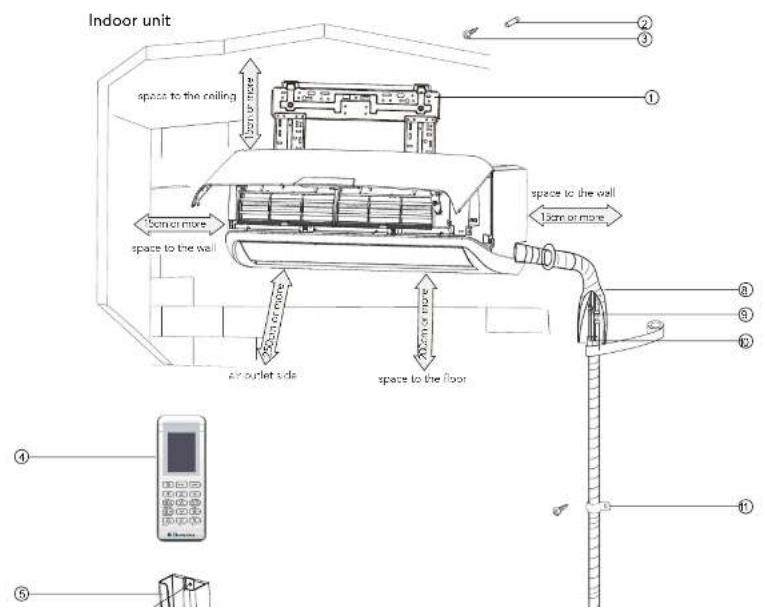
Important
- If your appliance is damaged due to improper installation your warranty may be void.
• Proper installation requires the use of a licensed installer. - You must keep full details of the installer including the license number and provide those details whenever you request a service for your appliance.
Installation checklist
Question
☐ Does the unit have adequate clearance from walls and ceiling in accordance to installation instructions?
☐ Is the unit mounted to allow condensate to flow freely toward the outside?
☐ Does outdoor section have adequate clearance in accordance to installation instructions?
□ Is the unit securely mounted?
☐ Is the unit readily accessible without special equipment?
☐ Has the appropriate size circuit and fuse/circuit breaker been fitted?
□ Has the unit been tested and confirmed to operate correctly?
□ Has the user of the air conditioner been shown how to use the air conditioner?
CUSTOMER: PLEASE RETAIN WITH YOUR PURCHASE DOCUMENTS IN A SAFE PLACE
Model Number
Serial Number
Installation site instructions
A proper installation site is vital for correct and efficient operation of the unit.
Avoid the following sites where:
• strong heat sources, vapour, flammable gas or volatile liquids are emitted.
- high-frequency electro-magnetic waves are generated by radio equipment, welders or medical equipment.
- salt-laden air prevails (such as close to coastal areas).
• the air is contaminated with industrial vapours and oils.
- the air contains sulphurous gas such as in hot spring zones.
• corrosion or poor air quality exists.
Indoor unit
- The air inlet and outlet should be kept clear of obstructions. Ensure the air can be blown through the whole room.
2 Select a site where the condensing water can be easily drained out, and where it is easily connected to the outdoor unit. - Select a place where it is out of reach of children.
- Select the place where the wall is strong enough to withstand the full weight and vibration of the unit.
5 Be sure to leave enough space to allow access for routine maintenance. - For optimum performance, the indoor unit should be installed on the wall at a height of 2 metres or more above the floor and at least 2.5 metres from the opposing wall.
- Make sure that the indoor unit is installed in accordance with installation dimension as below:
15 Note low temperature soldering alloys are not acceptable.
16. Minimum room space requirements as advised on the rating plate must be complied with.
17 Reusable mechanical connectors may not be used within indoors or within wall or ceiling cavities where a refrigerant leak can gather.
18 All refrigerant tubing shall be protected or enclosed to prevent damage.
Outdoor unit
1 Select a site where noise and outflow air emitted by unit will not annoy neighbours.
2 Select a site where there is sufficient ventilation.
3. Select a site where there is no obstruction blocking the inlet and outlet.
4 The site should be able to withstand the full weight and vibration of the unit.
5 Select a dry place, but do not expose the unit to direct sunlight or strong wind.
6 Make sure that the outdoor unit is installed in accordance with the installation instructions, and is convenient for maintenance and repair.
7 Select a place where it is out of reach of children and far from animals or plants.
8 Select a place where the unit keeps the horizontal and aligned position.
9 Select at a place that respects the minimum distances around the outdoor unit as below:

Rooftop installation
If the outdoor unit is installed on a roof structure, be sure to level the unit
Ensure the roof structure and anchoring method are adequate for the unit location.
If the outdoor unit is installed on roof structures or external walls, this may result in excessive noise and vibration, and may also be classed as non-serviceable installation.
Pipe Length Elevation and Additional Quantity of Gas
| Model Number | Discharge Pipe Diameter | Suction Pipe Diameter Standard Length (m) | Maximum Length (m) | Maximum Height (m) | Additional Refrigerant (g/m) | |
| KSV26HRE | O6.35 mm (1/4") | O9.52 mm (3/8") | 7.5 | 15 | 10 | 16 |
| KSV35HRE | O6.35 mm (1/4") | O9.52 mm (3/8") | 7.5 | 20 | 10 | 16 |
| KSV53HRE | O6.35 mm (1/4") | O12.70 mm (1/2") | 7.5 | 25 | 10 | 16 |
| KSV62HRE | O6.35 mm (1/4") | O15.88 mm (5/8") | 7.5 | 25 | 10 | 40 |
| KSV70HRE | O6.35 mm (1/4") | O15.88 mm (5/8") | 7.5 | 25 | 10 | 40 |
| KSV80HRE | O6.35 mm (1/4") | O15.88 mm (5/8") | 7.5 | 30 | 10 | 40 |
| KSV26CRE | O6.35 mm (1/4") | O9.52 mm (3/8") | 7.5 | 15 | 10 | 12 |
| KSV35CRE | O6.35 mm (1/4") | O9.52 mm (3/8") | 7.5 | 20 | 10 | 12 |
| KSV70CRE | O6.35 mm (1/4") | O15.88 mm (5/8") | 7.5 | 15 | 10 | 12 |
! caution
- The outdoor unit is charged with the refrigerant for standard pipe length of 7.5m.
- When the connecting pipe length is longer than the standard length, additional refrigerant should be added into the unit according to the above table through the service port on 3-way service valve on the outdoor unit.

Outdoor unit installation
Securing the outdoor unit
Anchor the outdoor unit by fixing the 4 holes existent in its base with 4 bolts and nuts of 10 mm tightly (not included). Place the outdoor unit over a horizontal concrete or rigid surface (never directly over grass or earth).

| Model | Outdoor unit dimensions W x D x H (mm) | Dimension A (mm) | Dimension B (mm) |
| KSV26HRE/CRE | 776 x 320 x 540 | 510 286 | |
| KSV35HRE/CRE | 842 x 320 x 596 | 540 286 | |
| KSV53HRE, KSV62HRE, KSV70CRE/HRE | 955 x 396 x 700 | 560 364 | |
| KSV80HRE |
Outdoor condensate drainage
- During heating operation, the condensate and defrosting water should be drained out reliably through the drain hose.
- The drain-water hole must be plugged. Whether to plug other holes will be determined by the installer according to actual conditions.
• Install the outdoor drain connector in the drain water hole on the chassis of the outdoor unit, and attach the drain hose to the connector so that the waste water formed in the outdoor unit can be drained out. - In case of a drain hose, the unit must be installed on a base more than 3cm in height.


caution
Indoor unit installation
Installing the mounting plate
1 Fit the mounting plate horizontally on the wall with five or more self-tapping screws (type ST4x25, item 3 on page 3).
2 Be sure that the mounting plate has been fixed firmly enough to withstand about 60kg. The weight should be evenly shared by every screw.
3 If the wall is made of brick, concrete or the like, drill five (5) or more holes of 5mm diameter in the wall. Insert clip anchor (item 2 on page 3) for appropriate mounting screws.
4. The water tray's outlet for the indoor unit has two-way drainage design. During installation, the indoor unit should slightly slant to water tray's outlet for smooth drainage of condensate water.
Fit the mounting plate and drill holes in the wall according to the wall structure and corresponding mounting points on the mounting plate. (dimensions are in mm unless otherwise stated)
| Model no. | Indoor unit dimension W x D x H (mm) | Mounting plate type |
| KSV26CRE 912 x 188 x 290 A | ||
| KSV26HRE 912 x 188 x 290 A | ||
| KSV35CRE 912 x 188 x 290 A | ||
| KSV35HRE 912 x 188 x 290 A | ||
| KSV53HRE 1000 x 219 x 326 B | ||
| KSV62HRE 1073 x 260 x 338 C | ||
| KSV70CRE | 1178 x 253 x 326 D | |
| KSV70HRE 1178 x 253 x 326 D | ||
| KSV80HRE 1178 x 253 x 326 D |
Mounting plate type A

Indoor unit installation
Mounting plate type C
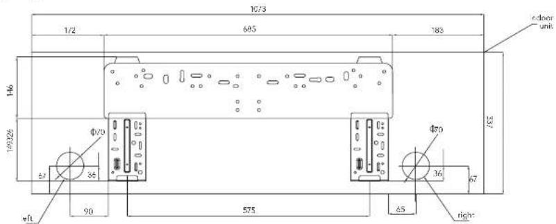
Mounting plate type D

Indoor unit installation
Drill piping hole
- Determine hole positions according to the diagram. Drill one (1) hole (Φ55 or Φ70 mm) in the wall at a slight downward slant to the outdoor side.
Piping hole Model
| Φ55 | KSV26CRE, KSV35CRE, KSV38HRE, KSV35HRE, KSV53HRE, |
| Φ70 | KSV70CRE, KSV62HRE, KSV70HRE, KSV80HRE |
- The inclination must be between 5mm and 10mm in order to ensure a good drain of condensed water generated by the indoor unit.
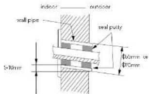
- Insert the wall pipe into the hole to prevent any wiring from being damaged when passing through the hole.
- Always use a wall hole conduit when drilling metal grids, metal plates or the like.
- For models with a cooling capacity greater than 4500W, remove and dispose the two polystyrene lateral rear supports from the indoor unit before the installation.
Installation of drain hose
- Connect the drain hose to the outlet pipe of the indoor unit. Bind the joint with vinyl tape.

- Put the drain hose into insulating pipe.

- Wrap the insulating pipe with wide vinyl tape to prevent the shift of insulating pipe. Slant the drain nose downward slightly for smooth drainage of condensed water.

Indoor unit installation

caution
- The insulating tube should be connected reliably with the sleeve outside the outlet pipe.
- The drain nose should be slanted downward slightly, without distortion, bulge or fluctuation.

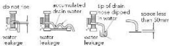
do not block water flow with a rise

do not put the end of the hose in water
- Do not put the outlet in the water.

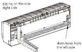
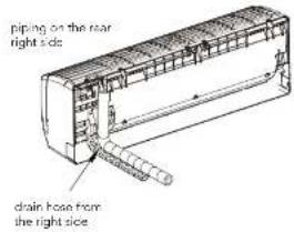
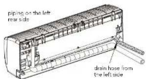
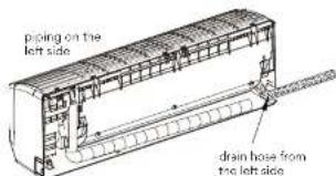
The piping can be output from right, rear right, left or rear left of the indoor unit body.
- When routing the piping and wiring from the left or right side of indoor unit, cut off the tailings from the chassis when necessary (see figure below)

- The drain hose can be connected at two different positions. Use the most convenient position and, if necessary, exchange the position of drain cap and drain hose;
• The drain hose is connected at the rear left side of the indoor unit when you receive the product.


Follow the instructions below for exchanging the position of the drain cap and drain hose from the left to the right side.
a. Pull out the drain cap at the rear right of the indoor unit.

is. Dull out+the desire to see with the same left of the
Indoor unit installation
d. Insert the drain hose into the drain hole at the rear right of the indoor unit.

- Arrange the pipe in the most convenient direction and position.
! caution
When refrigerant pipes and the drain pipe are fitted to the same side, ensure that the bulk does not push the unit away from the wall when in its final position.

Indoor unit installation
- Take out the piping from body case, wrap the piping, power cords, drain hose with the tape and then make them pass through the piping hose.
Do not put any object in the drain pan located in the rear of the indoor unit, as the condensed water is gathered there and piped out of the room.

- Hang the mounting slots of the indoor unit on the upper hooks of the mounting plate and check if it is firm enough.
To ease the piping installation, put a spacer between the indoor unit and the wall. Remove the spacer once finished.

- Press the lower left and right sides of the unit against the mounting plate until the lower hooks engage into their slots. Ensure the unit is firmly fitted.


caution
- Connect the indoor unit first, then the outdoor unit.
- Do not plug the cable to the indoor unit. That must be done at a later stage.
-
Turn the cable lightly to make the connection easier.
-
The installation site should be 2 metres or more above the floor.
Indoor unit installation
Refrigerant pipe connection
The main cause of refrigerant leakage is due to defects in the flaring work. Carry out flaring work using the following procedure: Note: When using refrigerant R32, a reusable flared connection is the only allowed pipework on the outside of any building. Hence the supplied "once only" flare fitting must be used unless all welded connections are used. If welded connections are used, no low temperature solder is permitted.
a. Cut the pipes and the cable
Use the piping kit accessory (if applicable) or pipes purchased locally. Measure the distance between the indoor and the outdoor unit. Cut the pipes a little longer than the measured distance. Cut the cable 1.5m longer than the pipe length.

b. Burr removal
Completely remove all burs from the cut cross section of pipe/tube. Face the end of the copper pipe/tube in a downward.

caution
It is not possible to put them on after flaring work.
d. Flaring work
Carry out flaring work using flaring tool as shown below
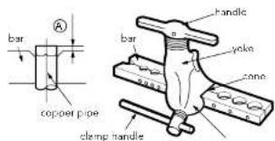
Firmly hold copper pipe in a die according to the dimension shown in the table below.
| Outer diameter (mm) | A (mm) | |
| Max. Min. | ||
| 6.35 (1/4") | 1.3 0.7 | |
| 9.52 (3/8") | 1.6 1.0 | |
| 12.70 (1/2") | 1.8 1.0 | |
| 15.88 (5/8") | 2.4 2.2 | |
e. Check
Compare the flare work with the adjacent diagram.
If the pipe has any defect, cut off the enlarged section and redo the work.
Indoor unit installation
Piping connection - indoor unit
a. Connecting the indoor unit tubing to the connection piping Align the centres of the pipes and sufficiently tighten the flare nut with your hands first.
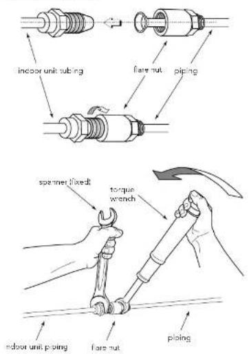
b. Wrap the insulation material around the connecting portion Cover the indoor unit pipe and the connection pipe with the heat insulation material. Bind them together with vinyl tape so that there is no gap.

Isolate the suction pipe from the liquid pipe.

Wrap the insulated pipes with vinyl tape in the rear section for pipe housing. Fasten the power cable to the pipes with vinyl tape.


Indoor unit installation
c. Positioning the indoor unit:
Remove the spacer.
Hook the indoor unit onto the upper portion of the mounting plate (engage the hooks of the mounting plate into the openings at the rear top of the indoor unit). Ensure that the hooks are properly seated on the mounting plate by moving the indoor unit in all directions.
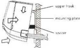
Press the lower left and right sides of the unit against the mounting plate until the hooks engage into their slots (clicking sound).

b. Then, tighten the flare nut with torque wrench until the wrench clicks.

Make sure to follow the torque table value as below:
| Outer diameter (mm) Torque (N.m) | |
| 6.35 (1/4") | 15-16 |
| 9.52 (3/8") | 31-32 |
| 12.70 (1/2") | 40-41 |
| 15.88 (5/8") | 45-46 |
Piping formation
a. Form the piping by wrapping the connecting portion of the indoor unit with insulation material and secure it with narrow vinyl tape and wide vinyl tape.
If you want to connect an additional drain hose, the end of the drain hose outlet should be routed above the ground. Secure the drain hose appropriately.
b. In cases where the outdoor unit is installed below the indoor unit level.
Indoor unit installation Safety precautions
c. In cases where the outdoor unit is installed above the indoor unit level:
Wrap the piping and connecting cable from bottom to top.
Form a trap to prevent water from entering the room.
Secure the wrapped piping along the exterior wall using saddle or equivalent.

Note: all refrigerant piping must be protected against mechanical damage
Electrical safety rules before starting the installation:
- A dedicated power supply circuit and breaker should be provided for the products which are not supplied with a service cord and plug in accordance with local electrical safety regulations.
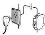
- The circuit breaker must have the functions of magnetic tripping and heat tripping to prevent short circuit and overload.
- The appliance shall be installed in accordance with national wiring regulations.
- A circuit breaker with proper capacity must be installed according to AS3000 and applicable local electrical safety regulations.
- In case of problems in power supply, the air conditioner must not be installed before the customer fixes the problem.
- Be sure the power supply matches the air conditioner.
- Ensure the live wire, neutral wire and earth wire in the power socket are properly connected.
- Inadequate or incorrect electrical connections may cause electric shock, fire or some electrical parts to malfunction.
- Before performing any electrical work, turn off the main power to the system.
Earthing requirements
- Air conditioners are type 1 electric appliances. The unit must be
Installation
Indoor electric wiring
Note: for correct operation of the air conditioner and standby power modes the mains power should be supplied to the indoor unit.
- Open the front panel and remove the wiring cover by loosening the screw.
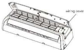
-
Route the power connection cable from back of the indoor unit and pull it toward the front through the wiring hole for connection.
-
Connect and screw the wires onto the terminal block as identified by their colours.
KSV26CRE, KSV35CRE models

KSV26HRE, KSV35HRE models
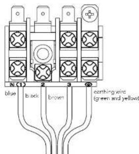
- Wrap wires that are not connected with insulating tape so that they do not touch any electrical or metal parts.
- Secure the wires firmly with the cable clamp.
- Put the wiring cover back and screw it.
- Re install the front panel.
! warning
All wires between indoor and outdoor units must be connected by a qualified electric contractor.
If the length of the power cord is not enough, please contact your installer for now a power cord. Lengthening the power cord by yourself is dangerous and illegal.
Installation
Outdoor electric wires
- When required, remove the handle on the right side plate of outdoor unit by loosening the screw.

- Take off wire cable clamp, Connect and screw the power connection cable and signal control wire (for reverse cycle models only) onto the terminal block following corresponding identification numbers and colours on the terminal blocks of indoor and outdoor units.
- To prevent water from entering, make a trap ("U") in the connection wires (see page 16).
- Wrap wires that are not connected with insulating tape so that they do not touch any electrical or metal parts.
- Fix the power connection wires with wire clamps.
- Reinstall the handle.
KSV26CRE, KSV26HRE, KSV35CRE, KSV35HRE models

caution
After confirming the above conditions, prepare the wiring as follows:
- The screws which lasten the wiring to the terminal block may come loose from vibrations during transportation.
- Check and make sure all screws are well fixed. Otherwise, it could cause burn-out of the wires.
- Be sure the circuit capacity is sufficient.
- Ensure the starting voltage is maintained at over 90% of the rated voltage marked on the nameplate.
- Confirm that the cable thickness is as specified in the power source specification.
- Always install a Residual Current Device (RCD) in wet or moist area.
- The following may be caused by voltage drop: vibration of a contactor, which will damage the contact point, fuse blowing disturbance of the normal function of the overload.
- The means for disconnection from a power supply shall be incorporated in the fixed wiring and have an air gap contact separation of at least 3mm in each active (phase) conductor. Note: Powered accessories cannot be connected to these wiring points.
Installation
Checking the drainage
a. Open and lift the indoor unit front panel.
I hold the lower part of the left and right sides of the panel, pull it against you and lift it stops with a full support from the bracket.

b. Check the drainage
Carefully pour a glass of water on the evaporator.
Ensure the water flows through the drain hose of the indoor unit without any leakage and goes out the drain exit.

natural_image
Technical line drawing of a mechanical component with internal structure and mounting holes (no text or symbols)Do not place drain piping as indicated below.
Air purging and leakage test
Note: Any brazed connections must be completed before evacuation and prior to the release of any refrigerant into the refrigerating components.
Air and moisture in the refrigeration system have undesirable effects as indicated below:
• System pressure increase
• Rise of the operating current.
• Cooling or heating efficiency drops.
- Moisture in the refrigeration circuit may freeze and block the capillary tubing.
- Water may load to corrosion of parts in the refrigeration system.
Therefore, the indoor unit and tubing between the indoor and outdoor units must be tested for leakage and evacuated to remove any non-condensables and moisture from the system.
Air purging with a vacuum pump
- Preparation
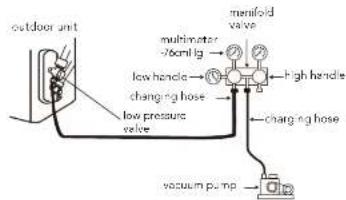
Check that each tube (both liquid and gas side tubes) between the indoor and outdoor units have been properly connected and all wiring for the test has been completed. Remove the service valve
Installation

flowchart
graph LR
    A["Outdoor unit"] --> B["Box A"]
    B --> C["Gas side"]
    B --> D["Liquid side"]
    C --> E["Indoor unit"]
    D --> E
    E --> F["Half union"]
    G["High stop valve (2-way valve)"] --> B

caution
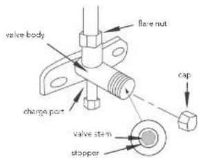
A: Low pressure valve (3-way) - gas side.
B: High pressure valve (2 way) - liquid side.
C and D: they are the ends of indoor unit connection
5 Keep vacuuming for more than 15 minutes and make sure the reading of multimeter is -1.0 x 10 Pa (-76cmHg). Then fully close the low handle of manifold valve and stop the operation of the vacuum pump.
6 Turn the stem of the stop valve B (2-way valve) about 45 counterclockwise for 6-7 seconds after the gas coming out, then tighten the flare nut again. Make sure the pressure display in the pressure indicator is a little higher than the atmosphere pressure.
7 Remove the charge hose from the low pressure charge port.
8 Fully open the valve stems of A (3-way valve) and B (2-way valve).
9 Securely tighten the stem cap.
Make sure to follow the torque table value as below:
Outer diameter (mm) Torque (N.m)
6.25%
15.12
Testing the air conditioner
Soapy water method
Apply soapy water or liquid neutral detergent on all valves and pipe connections (A, B, C and D, refer to the figure below) involved in installation by a soft brush to check for leakage. If bubbles come out, the pipes have leakage.

Leak detector
Use the leak detector to check for leakage.
Electrical safety check
Perform the electric safety check after completing the installation:
↑ Earthing work
After finishing earthing work, measure the earthing resistance by visual detection and earthing resistance tester.
- Electrical leakage check (perform while the test is running)
Operation test method
- Switch on power and press "ON/OFF" button on the remote controller to start the operation. Press MODE button to select the COOL, HEAT (if applicable), FAN to check if all the functions work well.
- When the ambient temperature is lower than 16°C, the unit can not be set on the remote control to work in COOL mode. Please use the Emergency Operation mode which is used only when the remote is unavailable or in case of maintenance.


Pump down
When relocating or disposing of the air conditioner, pump down the system following the procedure below so that no refrigerant is released into the atmosphere.
- Connect the hose of manifold valve to the charge port of stop valve on the gas pipe side of the outdoor unit.
- Close the stop valve on the gas pipe side almost
Post installation checks
| Items to be checked Possible malfunction | |
| Has the unit been fixed firmly? | The unit may drop, shake or omit noise |
| Have you done the refrigerant leakage tax? It may cause insufficient cooling (heating) | |
| Is thermal insulation sufficion? | It may cause condensation |
| Is water drainage satisfactory? It may cause water leakage | |
| Is the voltage in accordance with the rated voltage marked on the nameplane? | It may cause electric malfunction or damage the unit |
| Is the electric wiring or piping connection installed correctly and securely? | It may cause electric malfunction or damage the parts |
| Has the unit been securely earthed? It may cause electrical leakage | |
| Is the power cord specified? It may cause electric malfunction or damage the parts | |
| Is the inlet or outlet blocked? | It may cause insufficient cooling (heating). |
| Is the length of connection pipes and refrigerant capacity recorded? | The refrigerant capacity is not accurate |
Notes

Electrolux Warranty
FOR SALES IN AUSTRALIA AND NEW ZEALAND
APPLIANCE: KELVINATOR SPLIT SYSTEM AIR CONDITIONER
This document sets out the terms and conditions of the product warranties for Electrolux Appliances. It is an important document. Please keep it with your proof of purchase documents in a safe place for future reference should you require service for your Appliance.
- In this warranty:
(a) 'acceptable quality' as referred to in clause 10 of this warranty has the same meaning referred to in the ACL;
(b) 'ACL' means Schedule 2 to the Competition and Consumer Act 2010;
(c) 'Appliance' means any Electrolux product purchased by you and accompanied by this document;
(d) 'ASC' means Electrolux authorised service centres;
(a) 'Electrolux' means Electrolux Home Products Pty Ltd of 163 O'Riordan Street, Mascox NSW 2020, ABN 51 004 762 341 in respect of Appliances purchased in Australia and Electrolux (NZ) Limited (collectively 'Electrolux') of 3-5 Nall Burgess Road, Mount Wellington, in respect of Appliances purchased in New Zealand;
(f) 'major failure' as referred to in clause 10 of this warranty has the same meaning referred to in the ACL and includes a situation when an Appliance cannot be repaired or it is uneconomic for Electrolux, at its discretion, to repair an Appliance during the Warranty Period;
(g) 'Warranty Period' means the Appliance is warranted against manufacturing defects in Australia and New Zealand for the period of 60 months, subject to this warranty and to the customer meeting the Warranty Condition.
(h) 'Warranty Condition' means:
(i) evidence by the customer that the Appliance was installed by a licensed air conditioner installer in Australia and in accordance with Electrolux installation guidelines as set out in the installation manual;
(i) the Appliance rating is correct for the size and thermal characteristics of the room;
(iii) the Appliance has been regularly maintained in accordance with Electroux guidelines set out in the user manual;
(iv) the Appliance is designed for providing human comfort and should be used under ambient conditions as set out in the product specifications and general air quality conditions.
(1) 'you' means the purchaser of the Appliance not having purchased the Appliance for re-sale, and 'your' has a corresponding meaning.
- This warranty only applies to Appliances purchased and used in Australia or New Zealand in normal domestic applications and is in addition to (and does not exclude, restrict, or modify in any way) any non-excludable statutory
In all instances, unless the Appliance is transported by Electrolux or an Electrolux authorised representative, the Appliance is transported at the owner's cost and risk while in transit to and from Electrolux or its ASC.
-
Proof of purchase is required before you can make a claim under this warranty.
-
You may not make a claim under this warranty unless the defect claimed is due to faulty or defective parts or workmanship. Electrolux is not liable in the following situations (which are not exhaustive):
(a) the Appliance is damaged by:
(i) accident
(i) misuse or abuse, including failure to properly maintain or service
(ii) normal wear and tear
(iv) power surges, electrical storm damage or incorrect power supply
(V) Incomplete or Improper installation
(M) incorrect, improper or inappropriate operation
(VI) Insect or vermin infestation
(vii) failure to comply with any additional instructions supplied with the Appliance;
(b) the Appliance is modified without authority from Electrolux In writing;
(c) the Appliance's serial number or warranty seal has been removed or defaced;
(c) the Appliance was serviced or repaired by anyone other than Electrolux, an authorised repairer or ASIC.
-
This warranty, the contract to which it relates and the relationship between you and Electrolux are governed by the law applicable where the Appliance was purchased. Where the Appliance was purchased in New Zealand for commercial purposes the Consumer Guarantee Act does not apply.
-
To the extent permitted by law and subject to your non-excludable statutory rights and warranties, Electrolux excludes all warranties and liabilities (other than as contained in this document) including liability for any loss or damage whether direct or indirect arising from your purchase, use or non use of the Appliance.
-
For Appliances and services provided by Electrolux in Australia, the Appliances come with a guarantee by Electrolux that cannot be excluded under the ACL. You are entitled to a replacement or refund for a major failure and for compensation for any other reasonably foreseeable loss or damage. You are also entitled to have the Appliance repairs or replaced if the Appliance fails to be of acceptable quality and the failure does not amount to a major failure. The benefits to you given by this warranty are in addition to your other rights and remedies under a law in relation to the Appliances or services to which the warranty relates.
Kelvinator

If you'd like further information about Kelvinator appliances, please visit your retailer, phone or email our Customer Care team or visit our website.
telephone: 1300 363 640
fax: 1800 350 067
email: customercare@electrolux.com.au
web: kelvinator.com.au
Kelvinator. We are part of the Electrolux family. Share more of our thinking at electrolux.com.au
- Kelvinator
- Congratulations Contents
- Important safety instructions Notice for installation
- R300 refrigerant warning
- caution
- warning
- Minimum floor areas
- Items required for installation
- Components
- Important
- Installation checklist
- Installation site instructions
- Indoor unit
- Outdoor unit
- Rooftop installation
- ! caution
- Outdoor unit installation
- Securing the outdoor unit
- Outdoor condensate drainage
- Indoor unit installation
- Installing the mounting plate
- Drill piping hole
- Installation of drain hose
- Refrigerant pipe connection
- a. Cut the pipes and the cable
- b. Burr removal
- d. Flaring work
- e. Check
- Piping connection - indoor unit
- c. Positioning the indoor unit:
- Piping formation
- Indoor unit installation Safety precautions
- Earthing requirements
- Installation
- Indoor electric wiring
- ! warning
- Outdoor electric wires
- Checking the drainage
- Air purging and leakage test
- Air purging with a vacuum pump
- Outer diameter (mm) Torque (N.m)
- Testing the air conditioner
- Soapy water method
- Leak detector
- Electrical safety check
- Operation test method
- Pump down
- Electrolux Warranty
Brand : KELVINATOR
Model : KSV35HRE
Category : Air Conditioning