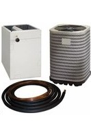
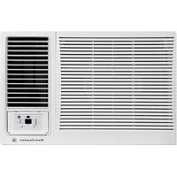
JS4BD018KB - Air Conditioning KELVINATOR - Free user manual and instructions
Find the device manual for free JS4BD018KB KELVINATOR in PDF.


| Product Type | Split Air Conditioner |
| Brand | Kelvinator |
| Model | JS4BD018KB |
| Cooling Capacity (BTU) | 18,000 |
| Energy Efficiency Ratio (EER) | 11.0 |
| Power Supply | 230V / 50Hz |
| Refrigerant | R410A |
| Air Flow (CFM) | 600 |
| Indoor Unit Dimensions (W x H x D) | 1000 x 300 x 200 mm |
| Outdoor Unit Dimensions (W x H x D) | 800 x 600 x 300 mm |
| Indoor Unit Weight | 12 kg |
| Outdoor Unit Weight | 35 kg |
| Noise Level - Indoor (dB) | 45 |
| Noise Level - Outdoor (dB) | 55 |
| Operating Modes | Cool, Dry, Fan, Auto |
| Additional Features | Timer, Sleep Mode, Auto Restart |
| Filter Cleaning Interval | Every 2 weeks |
| Recommended Professional Maintenance | Annually |
| Safety Protections | Overload, Short Circuit, Auto Restart |
| Available Spare Parts | Remote control, air filters, fan motor |
Frequently Asked Questions - JS4BD018KB KELVINATOR
User questions about JS4BD018KB KELVINATOR
0 question about this device. Answer the ones you know or ask your own.
Ask a new question about this device
Download the instructions for your Air Conditioning in PDF format for free! Find your manual JS4BD018KB - KELVINATOR and take your electronic device back in hand. On this page are published all the documents necessary for the use of your device. JS4BD018KB by KELVINATOR.
USER MANUAL JS4BD018KB KELVINATOR
INSTALLATION INSTRUCTIONS
S4BD SERIES - 018, 024, 030, 036, 042, 048, & 060 (1.5, 2, 2.5, 3, 3.5, 4, & 5 Ton)
IMPORTANT SAFETY INFORMATION ...... 2
AIR CONDITIONER INSTALLATION ....3
General Information 3
Before You Install this Unit....3
Locating the Air conditioner....3
Packaging Removal ....3
Ground Level....3
Roof Mount....3
Connecting Refrigerant Tubing between the Indoor & Outdoor Unit 4
ELECTRICAL WIRING......4
Pre - Electrical Checklist 4
Line Voltage....4
Comfort Alert™ Diagnostics Module ....5
24VAC Power Wiring 5
Thermostat Demand Wiring 5
Interpreting the Diagnostic LED's 5
LED Description....6
Grounding 6
Thermostat Low / Voltage Connections......6
AIR CONDITIONER MAINTENANCE....6
STARTUP & ADJUSTMENTS ......7
Pre - Start Checklist....7
Start-up Procedures....7
Air Circulation - Indoor Blower 7
System Cooling....7
System Heating....7
Refrigerant Charging....7
Charging the Unit in AC Mode with
Outdoor Temperatures Above 55° F......8
Application Notes for Using Charging Charts .....8
S4BD CHARGING CHARTS 8
Figure 3. Charging Chart for 1.5 Ton Units......8
Figure 4. Charging Chart for 2 Ton Units......9
Figure 5. Charging Chart for 2.5 Ton Units......9
Figure 6. Charging Chart for 3 Ton Units......10
Figure 7. Charging Chart for 3.5 Ton Units......10
Figure 8. Charging Chart for 4 Ton Units......11
Figure 9. Charging Chart for 5 Ton Units......11
S4BD CHARGING TABLES....12
Table 3. Charging Table for 1.5 Ton Units......12
Table 4. Charging Table for 2 Ton Units......12
Table 5. Charging Table for 2.5 Ton Units......13
Table 6. Charging Table for 3 Ton Units......13
Table 7. Charging Table for 3.5 Ton Units......14
Table 8. Charging Table for 4 Ton Units......14
Table 9. Charging Table for 5 Ton Units......15
ELECTRICAL DIAGRAMS & TABLES......16
Figure 10. W.D., Single Phase (1.5 - 5 Ton) ..... 16
Table 10. Comfort Alert LED Diagnostics......17
Table 11. Module Wiring Troubleshooting......18
INSTALL. / PERFORMANCE CHECKLIST ..... 20
REPLACEMENT PARTS......20
IMPORTANT
ATTENTION INSTALLERS:
It is your responsibility to know this product better than your customer. This includes being able to install the product according to strict safety guidelines and instructing the customer on how to operate and maintain the equipment for the life of the product. Safety should always be the deciding factor when installing this product and using common sense plays an important role as well. Pay attention to all safety warnings and any other special notes highlighted in the manual. Improper installation of the furnace or failure to follow safety warnings could result in serious injury, death, or property damage.
These instructions are primarily intended to assist qualified individuals experienced in the proper installation of this appliance. Some local codes require licensed installation/service personnel for this type of equipment. Please read all instructions carefully before starting the installation. Return these instructions to the customer's package for future reference.
DO NOT DESTROY. PLEASE READ CAREFULLY & KEEP IN A SAFE PLACE FOR FUTURE REFERENCE.
INSTALLER: Please read all instructions before servicing this equipment. Pay attention to all safety warnings and any other special notes highlighted in the manual. Safety markings are used frequently throughout this manual to designate a degree or level of seriousness and should not be ignored.
WARNING indicates a potentially hazardous that if not avoided, could result in personal injury or death.
CAUTION indicates a potentially hazardous situation that if not avoided, may result in minor or moderate injury or property damage.
WARNING:
Shut off all electrical power to the unit before performing any maintenance or service on the system. Failure to comply may result in personal injury or death.
WARNING:
Unless noted otherwise in these instructions, only factory authorized parts or accessory kits may be used with this product. Improper installation, service, adjustment, or maintenance may cause explosion, fire, electrical shock or other hazardous conditions which may result in personal injury or property damage
WARNING:
S4BD Split System Air Conditioners are shipped charged with R410A refrigerant and ready for installation. If repairs make it necessary for evacuation and charging, it should only be attempted by qualified trained personnel thoroughly familiar with this equipment. Under no circumstances should the owner attempt to install and/or service this equipment. Failure to comply with this warning could result in property damage, personal injury, or death.
CAUTION:
This unit uses refrigerant R-410A. DO NOT use any other refrigerant in this unit. Use of another refrigerant will damage the unit.
⚠ WARNING:
The information listed below must be followed during the installation, service, and operation of this unit. Unqualified individuals should not attempt to interpret these instructions or install this equipment. Failure to follow safety recommendations could result in possible damage to the equipment, serious personal injury or death.
- The installer must comply with all local regulations which govern the installation of this type of equipment. Local codes and regulations take precedence over any recommendations contained in these instructions. Consult local building codes and the National Electrical Code (ANSI CI) for special installation requirements.
- All electrical wiring must be completed in accordance with local, state and national codes and regulations and with the National Electric Code (ANSI/NFPA 70) or in Canada the Canadian Electric Code Part 1 CSA C.22.1.
- This equipment contains liquid and gaseous refrigerant under high pressure. DO NOT USE ANY PORTION OF THE CHARGE FOR PURGING OR LEAK TESTING. Installation or servicing should only be performed by qualified trained personnel thoroughly familiar with this type equipment.
- Fully annealed, refrigerant grade copper tubing should be used when installing the system. Refrigerant suction line tubing should be fully insulated.
- Installation of equipment may require brazing operations. Installer must comply with safety codes and wear appropriate safety equipment (safety glasses, work gloves, fire extinguisher, etc.) when performing brazing operations.
- Follow all precautions in the literature, on tags, and on labels provided with the equipment. Read and thoroughly understand the instructions provided with the equipment prior to performing the installation and operational checkout of the equipment.
- Refrigerant and electrical line should be routed through suitably waterproofed openings to prevent water from leaking into the structure.
AIR CONDITIONER INSTALLATION
General Information
The S4BD series air conditioner is designed only for outdoor rooftop or ground level installations. This unit has been tested for capacity and efficiency in accordance with AHRI Standards and will provide many years of safe and dependable comfort, providing it is properly installed and maintained. Abuse, improper use, and/or improper maintenance can shorten the life of the appliance and create unsafe hazards.
To achieve optimum performance and minimize equipment failure, it is recommended that periodic maintenance be performed on this unit. The ability to properly perform maintenance on this equipment requires certain mechanical skills and tools.
Before You Install this Unit
√ The cooling load of the area to be conditioned must be calculated and a system of the proper capacity selected. It is recommended that the area to be conditioned be completely insulated and vapor sealed.
√ Check the electrical supply and verify the power supply is adequate for unit operation. The system must be wired and provided with circuit protection in accordance with local building codes. If there is any question concerning the power supply, contact the local power company.
√ The indoor section (air handler, furnace, etc) should be installed before routing the refrigerant tubing. Refer to the indoor unit's installation instructions for installation details.
√ All units are securely packed at the time of shipment and upon arrival should be carefully inspected for damage prior to installing the equipment at the job site. Verify coil fins are straight. If necessary, comb fins to remove flattened or bent fins. Claims for damage (apparent or concealed) should be filed immediately with the carrier.
√ Please consult your dealer for maintenance information and availability of maintenance contracts. Please read all instructions before installing the unit.
Locating the Air Conditioner
- Survey the job site to determine the best location for mounting the outdoor unit.
- The outdoor unit should be installed no closer than 18 inches from the outside walls of the facility and in an area free from overhead obstructions to ensure unrestricted airflow through the outdoor unit.
- Sufficient clearance for unobstructed airflow through the outdoor coil must be maintained in order to achieve rated performance. See Figure 1 for minimum clearances to obstructions.
• Overhead obstructions (Figure 1), poorly areas, and areas subject to accumulation of debris should be avoided. - Consideration should be given to availability of electric power, service access, noise, and shade.
Packaging Removal
NOTE: To prevent damage to the tubing connections, carefully remove the carton and user's manual from the equipment. Discard the shipping carton.
Ground Level
Ground level installations must be located according to local building codes or ordinances and these requirements:
- Clearances must be in accordance with those shown in Figure 1.
- A suitable mounting pad (Figure 1) must be provided and separate from the building foundation. The pad must be level and strong enough to support the weight of the unit. The slab height must be a minimum of 2" (5 cm) above grade and with adequate drainage.
Roof Mount
- The method of mounting should be designed so that it does not overload roof structures or transmit noise to the interior of the structure. The roof must be structurally capable of handling the weight of the unit.
- Full perimeter support is required under the unit. Support must be made of weather resistant materials and installed prior to unit installation.
- The support must be built to raise the unit 6" above the roof.

Figure 1. Clearance Requirements

CAUTION:
When servicing, cover or seal openings to minimize the exposure of the refrigerant system to air to prevent accumulation of moisture and other contaminants.
After outdoor and indoor unit placement has been determined, route refrigerant tubing between the equipment in accordance with sound installation practices.
- When connecting refrigerant linesets together recommended that dry nitrogen be flowing through the joints during brazing to prevent internal oxidation and scaling.
- Refrigerant tubing should be routed in a manner that minimizes the length of tubing and the number of bends in the tubing. If precise forming of refrigerant lines is required, a copper tubing bender is recommended. Avoid sharp bends and contact of the refrigerant lines with metal surfaces.
- Refrigerant tubing should be supported in a manner that the tubing will not vibrate or abrade during system operation.
- Tubing should be kept clean of foreign debris during installation.
- Every effort should be made by the installer to ensure that the field installed refrigerant containing components of the system have been installed in accordance with these instructions and sound installation practices to insure reliable system operation and longevity.
- The maximum recommended interconne refrigerant line lengths is 75 ft. and the vertical elevation difference between the indoor and outdoor sections should not exceed 20 ft.
- A filter dryer is provided with the unit installed in the liquid line of the system. If the installation replaces a system with a filter dryer already present in the liquid line, the filter dryer must be replaced with the one supplied with the unit. The filter dryer must be installed in strict accordance with the manufacturer's installation instructions.
- Optional equipment such as liquid line valves, low ambient, etc., should be installed in strict accordance with the manufacturer's installation instructions.

WARNING:
To avoid risk of electrical shock, personal injury, or death, disconnect all electrical power to the unit before performing any maintenance or service. The unit may have more than one electrical supply.
Label all wires prior to disconnection when servicing the unit. Wiring errors can cause improper and dangerous operation.
- All electrical connections must be in compliance with all applicable local codes and ordinances, and with the current revision of the National Electric Code (ANSI/NFPA 70).
- For Canadian installations the electrical connections and grounding shall comply with the current Canadian Electrical Code (CSA C22.1 and/or local codes).
Pre-Electrical Checklist
√ Verify that the voltage, frequency, and phase of the supply source match the specifications on the unit rating plate.
√ Verify that the service provided by the utility is sufficient to handle the additional load imposed by this equipment. Refer to the unit wiring label for proper voltage wiring.
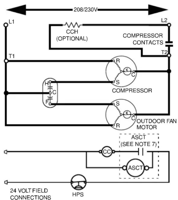
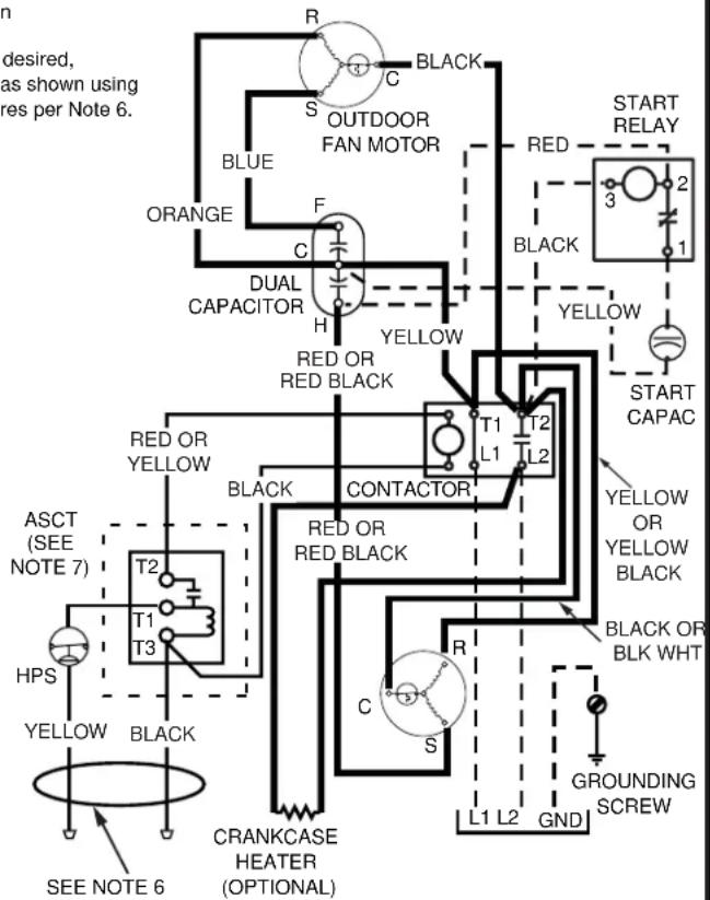
√ Verify factory wiring is in accordance with the unit wiring diagram (Figure 10 page 16). Inspect for loose connections.
Line Voltage
- A wiring diagram is located on the inside cover of the electrical box of the outdoor unit. The installer should become familiar with the wiring diagram before making any electrical connections to the outdoor unit.
- An electrical disconnect must be located within sight of and readily accessible to the unit. This switch shall be capable of electrically de-energizing the outdoor unit.
- Line voltage to the unit should be supplied from dedicated branch circuit containing the correct fuse or circuit breaker for the unit. Incoming field wiring and minimum size of electrical conductors and circuit protection must be in compliance with information listed on the outdoor unit data label. Any other wiring methods must be acceptable to authority having jurisdiction.
- The outdoor unit requires both power and control circuit electrical connections. Refer to the wiring diagram / schematic for identification and location of outdoor unit field wiring interfaces (Figure 10 page 16). Make all electrical connections in accordance with all applicable codes and ordinances.
-
Overcurrent protection must be provided at the branch circuit distribution panel and sized as shown on the unit rating label and according to applicable local codes. See the unit rating plate for minimum circuit ampacity and maximum overcurrent protection limits.
-
Provide power supply for the unit in accordance with unit wiring diagram, and the unit rating plate. Connect the line-voltage leads to the terminals on the contactor inside the control compartment.
- Use only copper wire for the line voltage power supply to this unit as listed in Table 1. Use proper code agency listed conduit and a conduit connector for connecting the supply wires to the unit. Use of rain tight conduit is recommended.
- 208/230 Volt units are shipped from the factory wired for 230 volt operation. For 208V operation, remove the lead from the transformer terminal marked 240V and connect it to the terminal marked 208V.
- Optional equipment requiring connection to the power or control circuits must be wired in strict accordance of the NEC (ANSI/NFPA 70), applicable local codes, and the instructions provided with the equipment.
| COPPER WIRE SIZE — AWG(1% Voltage Drop) | ||||
| Supply Wire Length-Feet | Supply Circuit Ampacity | |||
| 200 150 | 100 50 | |||
| 6 8 10 | 14 15 | |||
| 4 6 8 | 12 20 | |||
| 4 6 8 | 10 25 | |||
| 4 4 6 | 10 30 | |||
| 3 4 6 | 8 | 35 | ||
| 3 4 6 | 8 | 40 | ||
| 2 3 4 | 6 | 45 | ||
| 2 3 4 | 6 | 50 | ||
| 2 3 4 | 6 | 55 | ||
| 1 2 3 | 4 | 60 | ||
Wire Size based on N.E.C. for 60° type copper conductors.
Table 1. Copper Wire Size
Grounding

WARNING:
The unit cabinet must have an uninterrupted or unbroken electrical ground to minimize personal injury if an electrical fault should occur. Do not use gas piping as an electrical ground!
This unit must be electrically grounded in accordance with local codes or, in the absence of local codes, with the National Electrical Code (ANSI/NFPA 70) or the CSA C22.1 Electrical Code. Use the grounding lug provided in the control box for grounding the unit.
Comfort Alert™ Diagnostics Module (Select Models Only)
The Comfort Alert™ Diagnostics Module (Figure 2) is a breakthrough innovation that troubleshoots heat pump and air conditioning system failures and accurately detects the cause of electrical and system related failures without any sensors. The module installs easily in the electrical box of the outdoor unit near the compressor contactor. By monitoring and analyzing data from the Copeland scroll compressor and the thermostat demand, the module can accurately detect the cause of electrical and system related failures without any sensors. A flashing LED indicator communicates the ALERT code and a diagnostic key is also imprinted on the side of the module to quickly direct the technician to the root cause of a problem.
NOTE: This module does not provide safety protection! The Comfort Alert™ Diagnostics Module is a monitoring device and cannot control or shut down other devices.
24 VAC Power Wiring
The Comfort Alert™ module requires a constant nominal 24 VAC power supply. The module cannot be powered by the C terminal on a defrost board or other control board without experiencing nuisance alerts. NOTE: The wiring to the module's R & C terminals must be routed directly from the indoor unit or thermostat.
If the constant 24 VAC (R wire) is not present in the outdoor unit, use one of the spare wires in the thermostat cable to bring power to the module. Connect the other end of the spare wire to R at the indoor unit or thermostat.
Thermostat Demand Wiring
The Comfort Alert™ module requires a thermostat demand signal to operate properly. The thermostat demand signal input (labeled Y on the module), should always be connected to the compressor contactor coil. NOTE: When the coil is energized, the demand signal input is 24 VAC. When the coil is not energized, the demand signal input should be less than 0.5 VAC.

Figure 2. Comfort Alert™ Diagnostics Module
NOTES:
- Factory installed modules have different thermostat demand signal wiring. Always follow manufacturer wiring instructions when replacing the module.
• After the thermostat demand signal is connected, verify that 24 VAC across Y & C when demand is present.
Interpreting the Diagnostic LED's
When an abnormal system condition occurs, the Comfort Alert™ module displays the appropriate ALERT and/or TRIP LED will flash a number of times consecutively, pause and then repeat the process. To identify a Flash Code number, count the number of consecutive flashes.
Each time the module powers up, the last ALERT Flash Code that occurred prior to shut down is displayed for one minute. The module will continue to display the LED until the condition returns to normal or if 24 VAC power is removed from the module. See Table 10 (page 17) for flash code identification or Table 11 (page 18) for module wiring troubleshooting.
LED Description
- POWER LED (Green): indicates voltage is present at the power connection of the module.
- ALERT LED (Yellow): communicates an system condition through a unique flash code. NOTE: The ALERT LED will flash consecutively, pause and then repeat the process. The number of consecutive flashes, referred to as the Flash Code, correlates to a particular abnormal condition. Detailed descriptions of these ALERT Flash Codes are listed in Tables 10 & 11.
- TRIP LED (Red): indicates a demand signal is received from the thermostat, but current to the compressor is not detected by the module. The TRIP LED typically indicates if the compressor protector is open or the compressor has no power.
The scroll compressor's R (run), C (common), and S (start) wires are routed through the holes in the Comfort Alert™ module marked R, C, & S. NOTE: The common wire does not need to be routed through the module for it to operate.
Thermostat Connections
- Thermostat connections should be made in accordance with the instructions supplied with the thermostat and the indoor equipment.
- The outdoor unit is designed to operate from a 24 VAC Class II control circuit. The control circuit wiring must comply with the current provisions of the NEC (ANSI/NFPA 70) and with applicable local codes having jurisdiction.
- The low voltage wires must be properly connected to the units low voltage terminal block. Recommended wire gauge and wire lengths for typical thermostat connections are listed in Table 2.
- The thermostat should be mounted about above the floor on an inside wall. DO NOT install the thermostat on an outside wall or any other location where its operation may be adversely affected by radiant heat from fireplaces, sunlight, or lighting fixtures, and convective heat from warm air registers or electrical
| Thermostat Wire Gauge | Recommended T-Stat Wire Unit to T-Stat (Length in FT) | |
| 2-Wire (Heating) | 5-Wire (Heating/Cooling) | |
| 24 55 25 | ||
| 22 90 45 | ||
| 20 | 140 | 70 |
| 18 | 225 | 110 |
Table 2. Thermostat Wire Gauge
appliances. Refer to the thermostat manufacturer's instruction sheet for detailed mounting and installation information.
AIR CONDITIONER MAINTENANCE
⚠ WARNING:
To prevent electrical shock, personal injury, or death, disconnect all electrical power to the unit before performing any maintenance or service. The unit may have more than one electrical supply.
Proper maintenance is important to achieve optimum performance from the air conditioner. The ability to properly perform maintenance on this equipment requires certain mechanical skills and tools. If you do not possess these skills, contact your dealer for maintenance. Consult your local dealer about the availability of maintenance contracts. Routine maintenance should include the following:
- Inspect and clean or replace air filters at the beginning of each heating and cooling season, or more frequently if required.
- Inspect the condensate drain and outdoor coil at the beginning of each cooling season. Remove any debris. Clean the outdoor coil and louvers as necessary using a mild detergent and water. Rinse thoroughly with water.
- Inspect the electrical connections for tightness at the beginning of each heating and cooling season. Service as necessary.
CAUTION:
The unit should never be operated without a filter in the return air system. Replace disposable filters with the same type and size.
- Do not attempt to add additional oil to equipped with oil tubes. The compressor is hermetically sealed at the factory and does not require lubrication.
5 feet
motors
START UP & ADJUSTMENTS
Pre-Start Check List
√ Verify the indoor unit is level and allows proper condensate drainage.
√ Verify the outdoor coil and top of the unit are free from obstructions and debris, and all equipment access/control panels are in place.
√ Verify air filters are cleaned and properly installed.
√ Verify duct work is sealed to prevent air leakage.
√ Verify line voltage power leads are securely connected and the unit is properly grounded.
√ Verify low voltage wires are securely connected to the correct leads on the low voltage terminal strip.
√ Verify power supply branch circuit overcurrent protection is sized properly.
√ Verify the thermostat is wired correctly.
Start-Up Procedures
The thermostat's function mode should be set to OFF and the fan mode should be set to AUTO. Close all electrical disconnects to energize the system.
Air Circulation - Indoor Blower
- Set the thermostat system mode on OFF and the fan mode to ON.
- Verify the blower runs continuously. Check the air delivery at the supply registers and adjust register openings for balanced air distribution. If insufficient air is detected, examine ductwork for leaks or obstructions.
- Set the thermostat fan mode to AUTO and verify the blower stops running.
System Cooling
- Set the thermostat's system mode to COOL and the fan mode to AUTO. Gradually lower the thermostat temperature setpoint below room temperature and verify the outdoor unit and indoor blower energize.
- Verify blower wheel is spinning in direction indicated by arrow. Feel the air being circulated by the indoor blower and verify that it is cooler than ambient temperature. Listen for any unusual noises. If unusual sounds occur, determine the source of the noise and correct as necessary.
- Verify HI and LO refrigerant pressures.
- Allow the system to operate for several minutes and then set the temperature selector above room temperature. Verify the fan and compressor cycle off with the thermostat. NOTE: The blower should also stop unless fan mode is set to the ON position.
System Heating (optional)
- Set the thermostat's system mode to HEAT and the temperature mode above room temperature.
- Verify the optional heating equipment (furnace or electric heat) and indoor blower energize. Feel the air being circulated by the indoor blower and verify that it is warmer than ambient temperature. Listen for any unusual noises. If unusual sounds occur, determine the source of the noise and correct as necessary.
Refrigerant Charging
⚠ WARNING:
S4BD Split System Air Conditioners are shipped charged with R410A refrigerant and ready for installation. If repairs make it necessary for evacuation and charging, it should only be attempted by qualified trained personnel thoroughly familiar with this equipment. Under no circumstances should the owner attempt to install and/or service this equipment. Failure to comply with this warning could result in property damage, personal injury, or death.
After refrigerant line connections are completed, it is required that you leak check and evacuate the indoor section and all line connections (using proper methods) before finalizing the full system refrigerant charge.
- Refrigerant charging charts are applicable matched assemblies of NORDYNE equipment and listed airflows for the indoor coil. Refer to Figures 3 - 9 (pages 8 - 11) and Tables 3 - 9 (pages 12 - 15) for correct system charging.
- S4BD outdoor units with non-AHRI listed indoor coils are not recommended. Deviations from rated airflows or non-listed combinations may require modification to the expansion device and refrigerant charging procedures for proper and efficient system operation.
- The refrigerant charge can be checked and adjusted through the service ports provided external to the outdoor unit. Use only gage line sets which have a "Schrader" depression device present to actuate the valve.
- A high-pressure switch is factory-installed and located in the liquid line internal to the outdoor unit. The switch is designed to protect the system when very high pressures occur during abnormal conditions. Under normal conditions, the switch is closed. If the liquid pressure rises above 575 psig, then the switch will open and de-energize the outdoor unit. TI will close again once the liquid pressure decreases to 460 psig. Please note that the switch interrupts the thermostat inputs to the unit. Thus, when the switch opens and then closes, there may be a 5 minute short cycling delay before the outdoor unit will energize.
- A low-pressure switch (Select Models) is installed and located in the suction line internal to the outdoor unit. The switch is designed to protect the compressor from a loss of charge. Under normal conditions, the switch is closed. If the suction pressure falls below 5 psig, then the switch will open and deenergize the outdoor unit. The switch will close again once the suction pressure increases above 20 psig. Please note that the switch interrupts the thermostat inputs to the unit. When the switch opens and then closes, there will be a 5 minute short cycling delay before the outdoor unit will energize.
Charging the Unit in AC mode at outdoor temperatures above 55°F for optimized sub-cooling of 10°F - 12°F.
- With the system operating at steady-state, measure the liquid refrigerant pressure (in psig) at the outdoor unit service valve.
- Measure the liquid refrigerant temperature (in Fahrenheit) at the service valve.
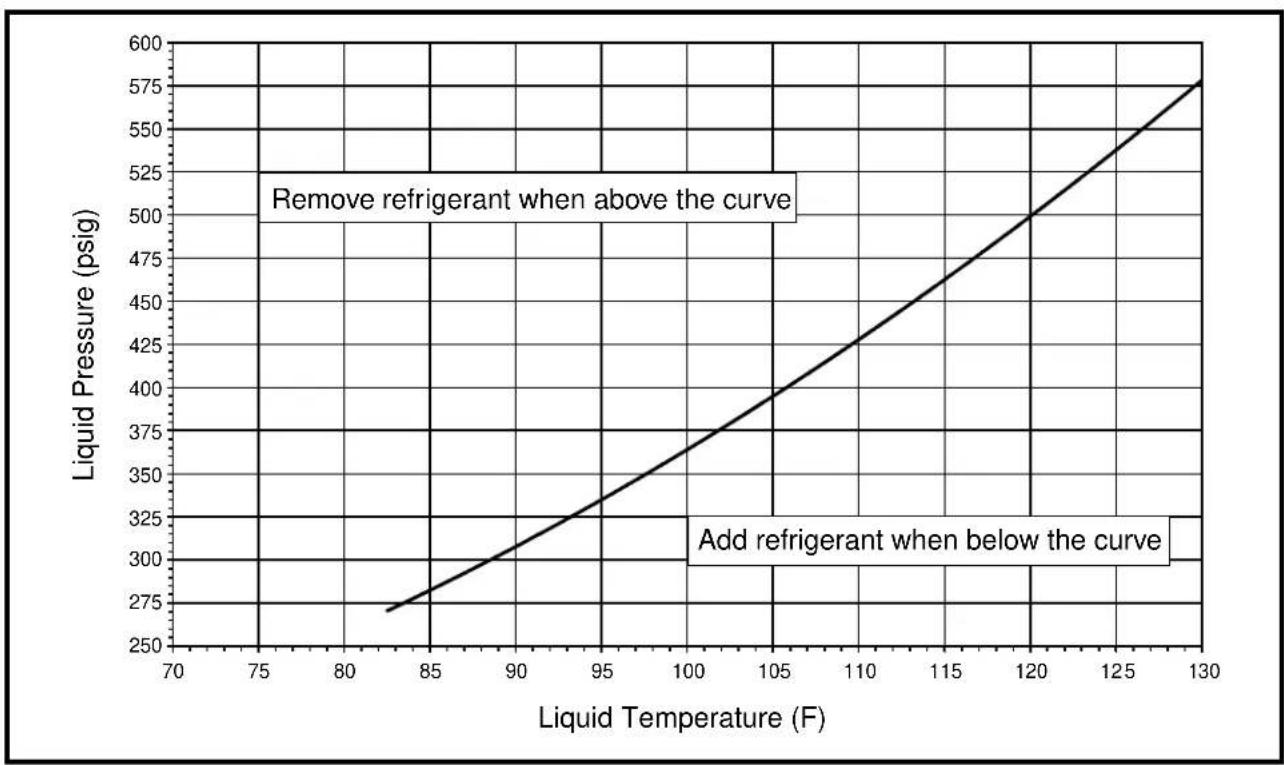
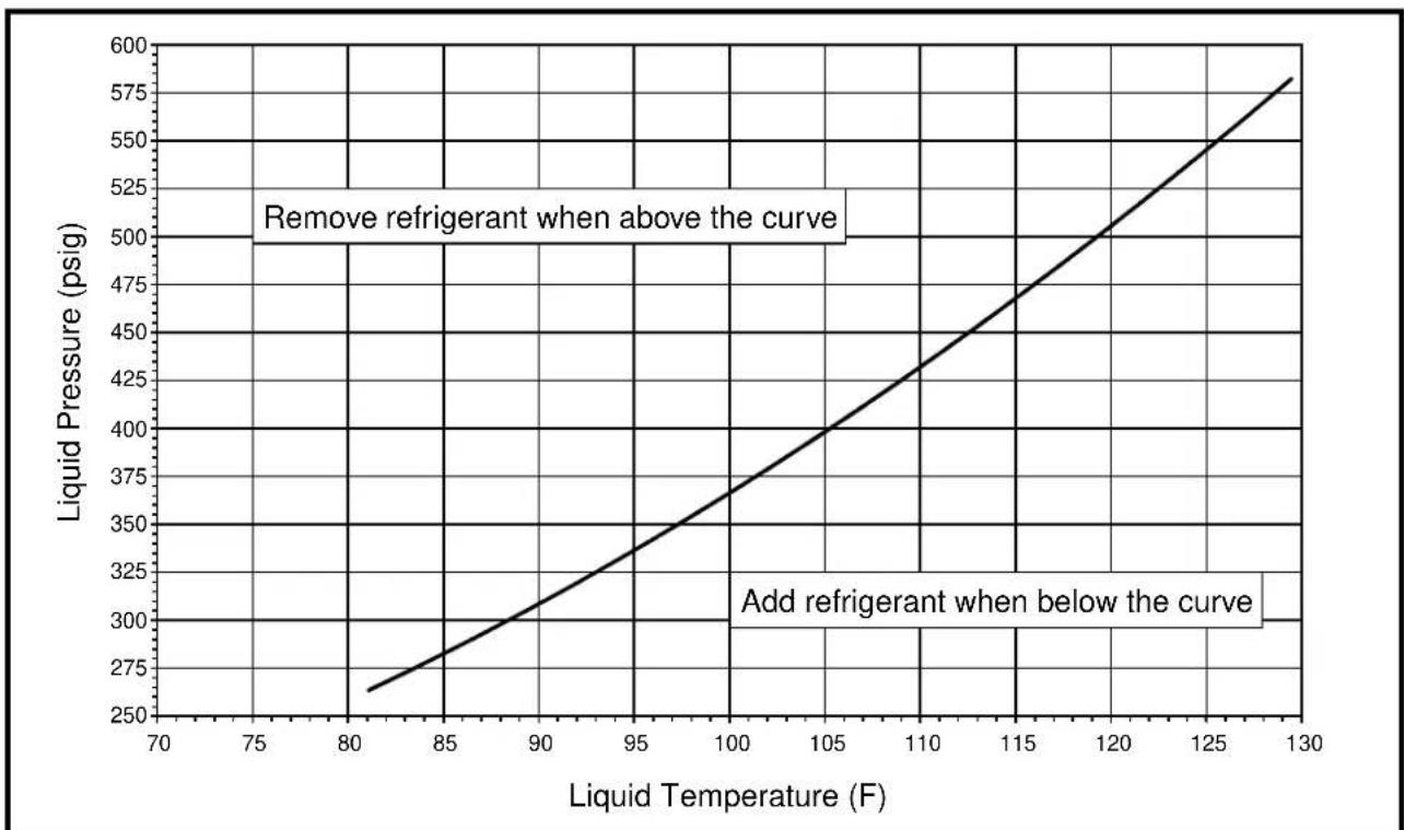
- Determine the required liquid refrigerant pressure from the appropriate charging chart (Figures 3 - 9).
- If the pressure measured in Step 1 is greater than the required liquid refrigerant pressure determined in Step 3, then there is too much charge in the system. Remove refrigerant and repeat Steps 1 through 3 until the system is correctly charged.
- If the pressure measured in Step 1 is less than the required liquid refrigerant pressure determined in Step 3, there is too little charge in the system. Add refrigerant and repeat Steps 1 through 3 until the system is correctly charged.
Application Notes for Using Charging Charts
- This equipment's cooling system co refrigerant under high pressure. Always use safe and environmentally sound methods when handling refrigerant handling or servicing the unit. Review the factory literature and safety warnings prior to servicing.
- When repairing system leaks, always use a nitrogen (inert) gas to protect the refrigerant system and pressure check the repair before re-charging. Always replace the filter-dryers when performing any repair to the
refrigeration system with one capable of acid removal. After completing the repairs, evacuate the system to 350 - 500 microns and weigh in the refrigerant to the amount specified on the unit rating label.
- Charging charts are valid for a variety of indoor, return air conditions and are most influenced by the outdoor ambient temperature, outdoor fan operation and the unit operating voltage. Before using these charts, make sure the unit is in a stable operating mode. As shown in the charging charts (Figures 3 - 9, pages 8 - 11), the ideal system sub-cooling can vary over the range of operation. Reference the charts to determine the ideal amount of sub-cooling for a given liquid pressure. Units charged to other values will not perform at the rated unit efficiency (EER) or rated Coefficient of Performance (COP) in heating mode.
- To inspect a systems operation using quality instruments, match the measured liquid temperature to the units chart. The measured liquid pressure reading should be within 3% of the charts value for most installations.
•ain\$ For systems that are operating with more than a 5% deviation, inspect the unit for the proper voltage and phase balance and the refrigeration system for leaks.
- Units that are operating at less than 95% of the nominal voltage or with a 2% phase imbalance may see a more significant deviation than the amount stated above.
- DO NOT use the charts in systems that have a fan cycling under low-ambient control. Refer to the low-ambient kit instructions for more information. (If applicable)
S4BD REFRIGERANT CHARGING CHARTS

line
| Liquid Temperature (F) | Liquid Pressure (psig) | | ---------------------- | --------------------- | | 83 | 260 | | 95 | 325 | | 100 | 350 | | 105 | 375 | | 110 | 400 | | 115 | 425 | | 120 | 450 | | 125 | 475 | | 130 | 550 |Figure 3. Charging Chart for S4BD-018 Series (1.5 Ton Units) - TXV Matches

line
| Liquid Temperature (F) | Liquid Pressure (psig) | | ---------------------- | ---------------------- | | 80 | 260 | | 90 | 320 | | 100 | 380 | | 110 | 440 | | 120 | 500 | | 130 | 560 | | 135 | 600 |Figure 4. Charging Chart for S4BD-024 Series (2 Ton Units) - TXV Matches
NOTE: Do not add or remove refrigerant if pressure reading is between the curves.
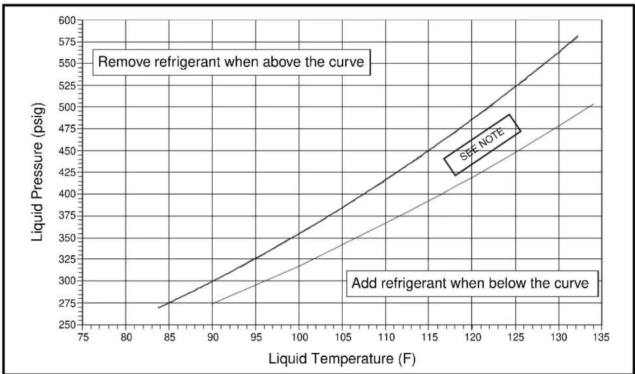
line
| Liquid Temperature (F) | Liquid Pressure (psig) | | ---------------------- | ---------------------- | | 85 | 275 | | 90 | 300 | | 95 | 325 | | 100 | 350 | | 105 | 375 | | 110 | 400 | | 115 | 425 | | 120 | 450 | | 125 | 475 | | 130 | 500 | | 135 | 525 |Figure 5. Charging Chart for S4BD-030 Series (2.5 Ton Units) - TXV Matches
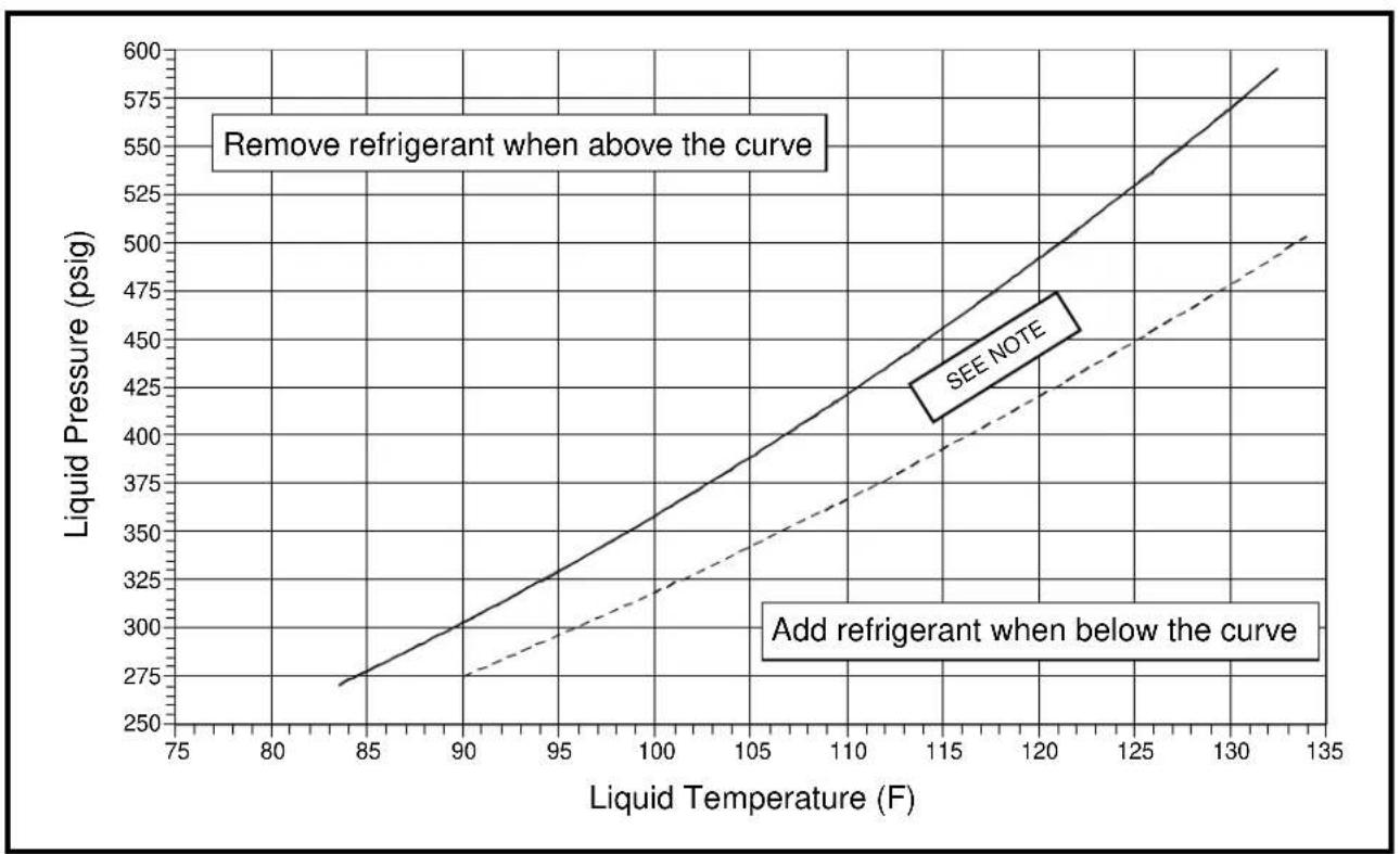
line
| Liquid Temperature (F) | Liquid Pressure (psig) | | ---------------------- | ---------------------- | | 85 | 275 | | 90 | 300 | | 95 | 325 | | 100 | 350 | | 105 | 375 | | 110 | 400 | | 115 | 425 | | 120 | 450 | | 125 | 475 | | 130 | 500 | | 135 | 525 |Figure 6. Charging Chart for S4BD-036 Series (3 Ton Units) - TXV Matches
NOTE: Do not add or remove refrigerant if pressure reading is between the curves.
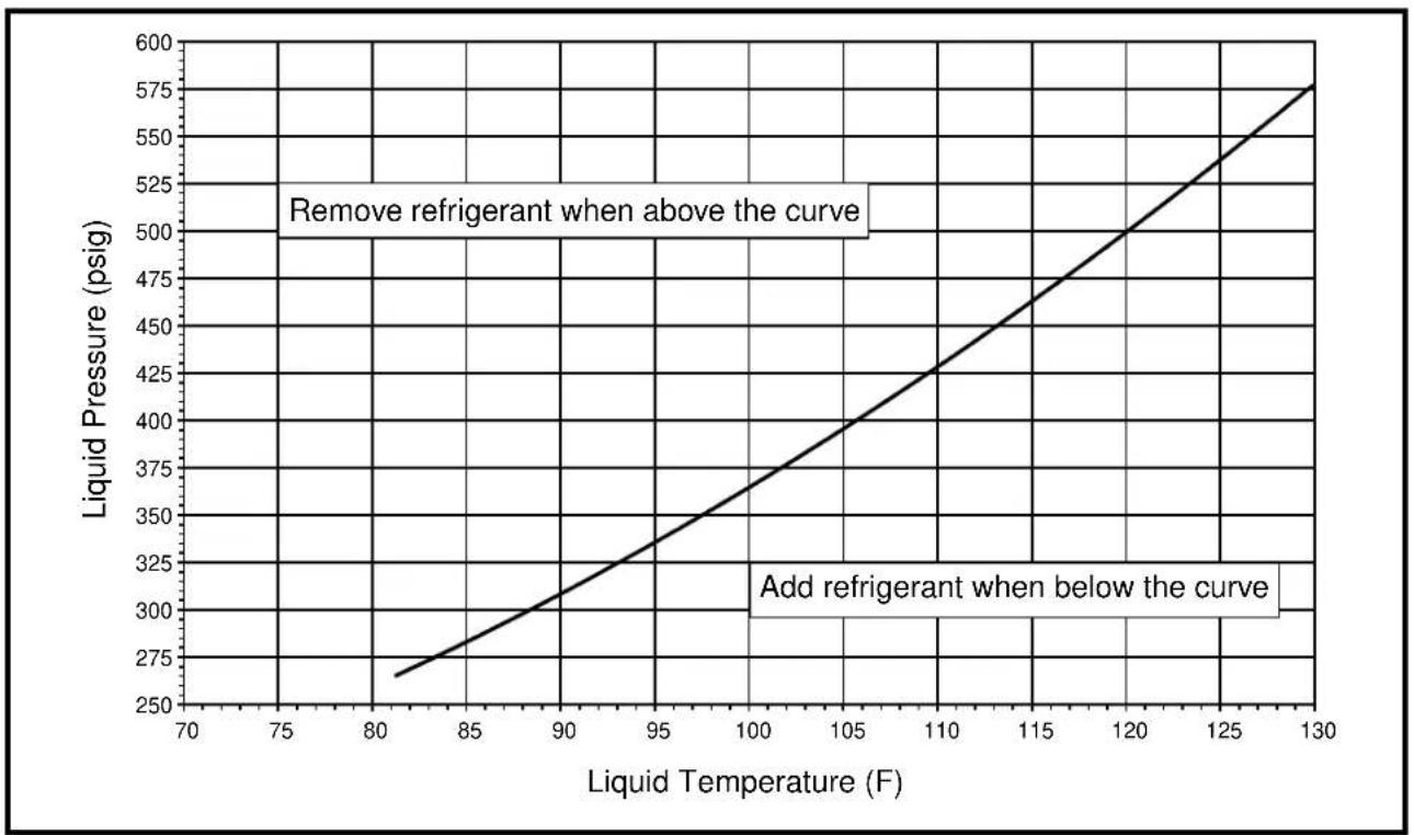
line
| Liquid Temperature (F) | Liquid Pressure (psig) | | ---------------------- | ---------------------- | | 80 | 275 | | 90 | 325 | | 100 | 375 | | 110 | 425 | | 120 | 475 | | 130 | 525 |Figure 7. Charging Chart for S4BD-042 Series (3.5 Ton Units) - TXV Matches
line
| Liquid Temperature (F) | Liquid Pressure (psig) | | ---------------------- | ---------------------- | | 83 | 270 | | 105 | 400 | | 120 | 500 | | 130 | 575 |Figure 8. Charging Chart for S4BD-048 Series (4 Ton Units) - TXV Matches
NOTE: Do not add or remove refrigerant if pressure reading is between the curves.
line
| Liquid Temperature (F) | Liquid Pressure (psig) | | ---------------------- | ---------------------- | | 80 | 260 | | 90 | 310 | | 100 | 370 | | 110 | 430 | | 120 | 500 | | 130 | 580 |Figure 9. Charging Chart for S4BD-060 Series (5 Ton Units) - TXV Matches
S4BD REFRIGERANT CHARGING TABLES - COOLING ONLY
LEGEND

Shaded boxes indicate flooded conditions.

Rated design values. The suction pressure will be lower than design value if outdoor air flow, entering dry bulb, or entering wet bulb temperatures are lower than design.
NOTES:
- All pressures are listed psig and all temperatures in °F
- Discharge temperatures GREATER than charted values indicate an UNDERCHARGED system.
- Discharge temperatures LESS than charted values indicate an OVERCHARGED system.
| Suct. Press. | OUTDOOR TEMPERATURE (°F) | |||||||||||||||
| 70 75 80 | 85 90 95 100 105 | |||||||||||||||
| Liq. Press. | Dis. Temp. | Liq. Press. | Dis. Temp. | Liq. Press. | Dis. Temp. | Liq. Press. | Dis. Temp. | Liq. Press. | Dis. Temp. | Liq. Press. | Dis. Temp. | Liq. Press. | Dis. Temp. | Liq. Press. | Dis. Temp. | |
| 132 257 137 | ||||||||||||||||
| 134 | 258 140 | 280 140 | ||||||||||||||
| 136 259 144 | 281 144 | 304 144 | ||||||||||||||
| 138 | 260 147 | 282 147 | 305 147 | 327 147 | ||||||||||||
| 140 261 150 | 283 150 | 306 150 | 328 150 | 351 150 | ||||||||||||
| 142 284 153 | 307 153 | 329 153 | 352 153 | 374 154 | ||||||||||||
| 144 308 156 | 330 156 | 353 157 | 375 157 | 398 157 | ||||||||||||
| 146 381 159 | 354 159 | 376 160 | 399 160 | 421 160 | ||||||||||||
| 148 383 162 355 162 | 377 163 | 400 163 | 422 163 | |||||||||||||
| 150 356 165 379 166 | 401 166 | 423 166 | ||||||||||||||
| 152 | 380 169 402 169 | 424 169 | ||||||||||||||
| 154 | 403 172 426 172 | |||||||||||||||
| 156 | 427 175 | |||||||||||||||
| 158 | ||||||||||||||||
Table 3. Charging Table for S4BD-018 Series (1.5 Ton Units) - Orifice Matches
| Suct. Press. | OUTDOOR TEMPERATURE (°F) | |||||||||||||||
| 70 75 80 | 85 90 95 100 105 | |||||||||||||||
| Liq. Press. | Dis. Temp. | Liq. Press. | Dis. Temp. | Liq. Press. | Dis. Temp. | Liq. Press. | Dis. Temp. | Liq. Press. | Dis. Temp. | Liq. Press. | Dis. Temp. | Liq. Press. | Dis. Temp. | Liq. Press. | Dis. Temp. | |
| 125 256 136 | ||||||||||||||||
| 127 | 257 139 | 280 139 | ||||||||||||||
| 129 258 143 | 281 143 | 304 143 | ||||||||||||||
| 131 | 259 146 | 282 146 | 305 146 | 328 146 | ||||||||||||
| 133 260 150 | 283 150 | 306 150 | 329 150 | 352 150 | ||||||||||||
| 135 284 153 | 307 153 | 330 153 | 353 153 | 376 153 | ||||||||||||
| 137 308 157 | 331 156 | 354 157 | 377 157 | 400 157 | ||||||||||||
| 139 333 160 | 355 160 | 378 160 | 401 160 | 424 160 | ||||||||||||
| 141 384 163 357 163 | 379 163 | 402 164 | 425 164 | |||||||||||||
| 143 358 166 381 166 | 403 167 | 426 167 | ||||||||||||||
| 145 | 382 169 405 170 | 428 170 | ||||||||||||||
| 147 | 406 173 429 173 | |||||||||||||||
| 149 | 431 176 | |||||||||||||||
| 151 | ||||||||||||||||
Table 4. Charging Table for S4BD-024 Series (2 Ton Units) - Orifice Matches
LEGEND

Shaded boxes indicate flooded conditions.

Rated design values. The suction pressure will be lower than design value if outdoor air flow, entering dry bulb, or entering wet bulb temperatures are lower than design.
NOTES:
- All pressures are listed psig and all temperatures in °F
- Discharge temperatures GREATER than charted values indicate an UNDERCHARGED system.
- Discharge temperatures LESS than charted values indicate an OVERCHARGED system.
| Suct. Press. | OUTDOOR TEMPERATURE (°F) | |||||||||||||||
| 70 75 80 | 35 90 95 100 105 | |||||||||||||||
| Liq. Press. | Dis. Temp. | Liq. Press. | Dis. Temp. | Liq. Press. | Dis. Temp. | Liq. Press. | Dis. Temp. | Liq. Press. | Dis. Temp. | Liq. Press. | Dis. Temp. | Liq. Press. | Dis. Temp. | Liq. Press. | Dis. Temp. | |
| 126 278 132 | ||||||||||||||||
| 128 | 280 135 | 303 137 | ||||||||||||||
| 130 281 138 | 305 140 | 328 141 | ||||||||||||||
| 132 | 283 141 | 306 143 | 330 144 | 354 145 | ||||||||||||
| 134 284 145 | 308 146 | 331 147 | 355 148 | 379 149 | ||||||||||||
| 136 309 149 | 333 150 | 357 151 | 380 152 | 404 154 | ||||||||||||
| 138 334 153 | 358 154 | 382 156 | 406 157 | 429 158 | ||||||||||||
| 140 360 157 | 384 159 | 407 160 | 431 161 | 454 162 | ||||||||||||
| 142 361 161 385 162 | 409 163 | 432 164 | 456 165 | |||||||||||||
| 144 387 164 411 166 | 434 167 | 457 168 | ||||||||||||||
| 146 | 412 168 436 170 | 460 171 | ||||||||||||||
| 148 | 438 172 462 173 | |||||||||||||||
| 150 | 464 176 | |||||||||||||||
| 152 | ||||||||||||||||
Table 5. Charging Table for S4BD-030 Series (2.5 Ton Units) - Orifice Matches
| Suct. Press. | OUTDOOR TEMPERATURE (°F) | |||||||||||||||
| 70 75 80 | 85 90 95 100 105 | |||||||||||||||
| Liq. Press. | Dis. Temp. | Liq. Press. | Dis. Temp. | Liq. Press. | Dis. Temp. | Liq. Press. | Dis. Temp. | Liq. Press. | Dis. Temp. | Liq. Press. | Dis. Temp. | Liq. Press. | Dis. Temp. | Liq. Press. | Dis. Temp. | |
| 124 261 137 | ||||||||||||||||
| 126 | 263 141 | 287 140 | ||||||||||||||
| 128 265 144 | 288 143 | 312 142 | ||||||||||||||
| 130 | 266 147 | 290 146 | 313 146 | 337 145 | ||||||||||||
| 132 268 150 | 292 149 | 315 149 | 339 148 | 362 147 | ||||||||||||
| 134 293 153 | 317 152 | 340 152 | 364 151 | 387 150 | ||||||||||||
| 136 318 155 | 342 154 | 365 154 | 389 153 | 413 152 | ||||||||||||
| 138 344 158 | 367 157 | 390 157 | 414 156 | 438 155 | ||||||||||||
| 140 345 161 369 160 | 392 160 | 416 159 | 439 158 | |||||||||||||
| 142 370 163 394 163 | 417 162 | 441 162 | ||||||||||||||
| 144 | 396 166 419 165 | 442 165 | ||||||||||||||
| 146 | 421 168 444 168 | |||||||||||||||
| 148 | 446 171 | |||||||||||||||
| 150 | ||||||||||||||||
Table 6. Charging Table for S4BD-036 Series (3 Ton Units) - Orifice Matches
LEGEND

Shaded boxes indicate flooded conditions.

Rated design values. The suction pressure will be lower than design value if outdoor air flow, entering dry bulb, or entering wet bulb temperatures are lower than design.
NOTES:
- All pressures are listed psig and all temperatures in °F
- Discharge temperatures GREATER than charted values indicate an UNDERCHARGED system.
- Discharge temperatures LESS than charted values indicate an OVERCHARGED system.
| Suct. Press. | OUTDOOR TEMPERATURE (°F) | |||||||||||||||
| 70 75 80 | 35 90 95 100 105 | |||||||||||||||
| Liq. Press. | Dis. Temp. | Liq. Press. | Dis. Temp. | Liq. Press. | Dis. Temp. | Liq. Press. | Dis. Temp. | Liq. Press. | Dis. Temp. | Liq. Press. | Dis. Temp. | Liq. Press. | Dis. Temp. | Liq. Press. | Dis. Temp. | |
| 130 257 | 135 | |||||||||||||||
| 132 | 259 | 138 | 282 | 138 | ||||||||||||
| 134 261 | 141 | 283 | 142 | 306 | 142 | |||||||||||
| 136 | 262 | 144 | 285 | 145 | 307 | 145 | 330 | 146 | ||||||||
| 138 264 | 146 | 286 | 147 | 309 | 149 | 331 | 149 | 354 | 150 | |||||||
| 140 268 | 150 | 310 | 151 | 333 | 152 | 355 | 153 | 378 | 153 | |||||||
| 142 31 | 2 154 | 334 | 155 | 357 | 156 | 379 | 156 | 402 | 157 | |||||||
| 144 336 | 158 | 358 | 159 | 381 | 160 | 404 | 160 | 426 | 161 | |||||||
| 146 337 | 161 | 359 | 162 | 382 | 163 | 405 | 163 | 428 | 164 | |||||||
| 148 361 | 165 | 383 | 166 | 406 | 166 | 429 | 167 | |||||||||
| 150 | 385 | 169 | 407 | 169 | 430 170 | |||||||||||
| 152 | 408 | 172 | 431 | 173 | ||||||||||||
| 154 | 432 | 176 | ||||||||||||||
| 156 | ||||||||||||||||
Table 7. Charging Table for S4BD-042 Series (3.5 Ton Units) - Orifice Matches
| Suct. Press. | OUTDOOR TEMPERATURE (°F) | |||||||||||||||
| 70 75 80 | 85 90 95 100 105 | |||||||||||||||
| Liq. Press. | Dis. Temp. | Liq. Press. | Dis. Temp. | Liq. Press. | Dis. Temp. | Liq. Press. | Dis. Temp. | Liq. Press. | Dis. Temp. | Liq. Press. | Dis. Temp. | Liq. Press. | Dis. Temp. | Liq. Press. | Dis. Temp. | |
| 125 261 136 | ||||||||||||||||
| 127 | 262 140 | 285 140 | ||||||||||||||
| 129 263 143 | 286 143 | 309 144 | ||||||||||||||
| 131 | 265 146 | 287 147 | 310 147 | 333 148 | ||||||||||||
| 133 266 149 | 289 149 | 311 151 | 334 151 | 357 151 | ||||||||||||
| 135 290 152 | 312 153 | 335 154 | 358 155 | 381 155 | ||||||||||||
| 137 314 156 | 336 157 | 359 158 | 382 159 | 405 159 | ||||||||||||
| 139 388 160 | 360 161 | 383 162 | 406 163 | 429 163 | ||||||||||||
| 141 389 163 361 164 | 384 165 | 407 166 | 430 166 | |||||||||||||
| 143 363 167 385 168 | 408 169 | 431 170 | ||||||||||||||
| 145 | 387 171 409 172 | 432 173 | ||||||||||||||
| 147 | 410 175 433 176 | |||||||||||||||
| 149 | 434 179 | |||||||||||||||
| 151 | ||||||||||||||||
Table 8. Charging Table for S4BD-048 Series (4 Ton Units) - Orifice Matches
LEGEND

Shaded boxes indicate flooded conditions.

Rated design values. The suction pressure will be lower than design value if outdoor air flow, entering dry bulb, or entering wet bulb temperatures are lower than design.
NOTES:
- All pressures are listed psig and all temperatures in °F
- Discharge temperatures GREATER than charted values indicate an UNDERCHARGED system.
- Discharge temperatures LESS than charted values indicate an OVERCHARGED system.
| Suct. Press. | OUTDOOR TEMPERATURE (°F) | |||||||||||||||
| 70 75 80 | 85 90 95 100 105 | |||||||||||||||
| Liq. Press. | Dis. Temp. | Liq. Press. | Dis. Temp. | Liq. Press. | Dis. Temp. | Liq. Press. | Dis. Temp. | Liq. Press. | Dis. Temp. | Liq. Press. | Dis. Temp. | Liq. Press. | Dis. Temp. | Liq. Press. | Dis. Temp. | |
| 121 264 149 | ||||||||||||||||
| 123 | 265 153 | 289 153 | ||||||||||||||
| 125 267 156 | 290 157 | 313 157 | ||||||||||||||
| 127 | 268 159 | 291 160 | 314 161 | 338 161 | ||||||||||||
| 129 270 162 | 293 163 | 316 164 | 339 165 | 362 165 | ||||||||||||
| 131 294 166 | 317 167 | 340 168 | 363 169 | 387 169 | ||||||||||||
| 133 319 170 | 342 171 | 365 172 | 388 173 | 411 173 | ||||||||||||
| 135 343 174 | 366 175 | 389 176 | 412 177 | 435 178 | ||||||||||||
| 137 345 177 368 178 | 391 179 | 414 180 | 437 181 | |||||||||||||
| 139 369 181 392 182 | 415 183 | 438 184 | ||||||||||||||
| 141 394 185 417 186 | 440 187 | |||||||||||||||
| 143 418 189 441 190 | ||||||||||||||||
| 145 | 442 193 | |||||||||||||||
| 147 | ||||||||||||||||
Table 9. Charging Table for S4BD-060 Series (5 Ton Units) - Orifice Matches
WIRING DIAGRAM
Split System Air Conditioner (Outdoor Section)
Single Phase
NOTES:
- Disconnect all power before servicing.
- For supply connections use copper conductors only.
- Not suitable on systems that exceed 150 volts to ground.
- For replacement wires use conductors suitable for 105 deg C.
- For ampacities and overcurrent protection, see unit rating plate.
- Connect to 24 vac/40ca/class 2 circuit. See furnace/airhandler installation instructions for control circuit and optional relay/transformer kits.
-
Anti-Short Cycle Timer (ASCT) may or may not be installed in the unit. If desired, ASCT is factory installed on select models only or may be field installed as shown using manufacturer's approved kit. If not present, connect Yellow and Black wires per Note 6.
-
Couper le courant avant de faire letretien.
- Employez uniquement des conducteurs en cuivre.
- Ne convient pas aux installations de plus de 150 volt a la terre.


710388B
(Replaces 710388A)
0109
Figure 10. Wiring Diagram for S4BD Single Phase Models
(1.5, 2, 2.5, 3, 3.5, 4, & 5 Ton Units)
COMFORT ALERT TROUBLESHOOTING
| Status LED Status LED Description Status LED Troubleshooting Information | ||
| POWER(Green LED) | Module has power Supply voltage is | present at module terminals |
| TRIP(Red LED) | Thermostat demand signal Yis present, but compressor is not running | Compressor protector is openCheck for high head pressureCheck compressor supply voltageOutdoor unit power disconnect is openCompressor circuit breaker or fuse(s) is openBroken wire or connector is not making contactLow pressure switch open if present in systemCompressor contactor has failed open |
| ALERTFlash Code 1(Yellow LED) | Long Run TimeCompressor is runningextremely long run cycles | Low refrigerant chargeEvaporator blower is not running— Check blower relay coil and contacts— Check blower motor capacitor— Check blower motor for failure or blockage— Check evaporator blower wiring and connectors— Check indoor blower control board— Check thermostat wiring for open circuitEvaporator coil is frozen— Check for low suction pressure— Check for excessively low thermostat setting— Check evaporator airflow (coil blockages or return airfilter)— Check ductwork or registers for blockageFaulty metering device— Check TXV bulb installation (size, location and contact)— Check if TXV/fixed orifice is stuck closed or defectiveCondenser coil is dirtyLiquid line restriction (filter drier blocked if present in system)Thermostat is malfunctioning— Solenoid plug not connected— Y2 not wired at Comfort Alert— Check thermostat sub-base or wiring for short circuit— Check thermostat installation (location, level)Comfort Alert failure |
| ALERTFlash Code 2(Yellow LED) | System Pressure Trip | High head pressure— Check high pressure switch if present in system— Check if system is overcharged with refrigerant— Check for non-condensable in system |
| Discharge or suction • Condenser | coil poor air circulation (dirty, blocked, damaged) | |
| Pressure out of limits | Condenser fan is not running— Check fan capacitor— Check fan wiring and connectors— Check fan motor for failure or blockage | |
| Compressor overloaded | Return air duct has substantial leakage | |
| If low pressure switch present in system, check Flash Code 1 information | ||
| ALERTFlash Code 3(Yellow LED) | Short Cycling / Compressor is running only briefly | Thermostat demand signal is intermittentLow line voltage (contact utility if voltage at disconnect is low)Excessive liquid refrigerant in compressorCompressor bearings are seized |
| ALERTFlash Code 4(Yellow LED) | Locked Rotor | Run capacitor has failedLow line voltage (contact utility if voltage at disconnect is low)Check wiring connectionsExcessive liquid refrigerant in compressorCompressor bearings are seizedMeasure compressor oil level |
| ALERTFlash Code 5(Yellow LED) | Open Circuit | Outdoor unit power disconnect is openCompressor circuit breaker or fuse(s) is openCompressor contactor has failed open— Check compressor contactor wiring and connectors— Check for compressor contactor failure (burned, pitted or open)— Check wiring and connectors between supply and compressor— Check for low pilot voltage at compressor contactor coil— High pressure switch is open and requires manual resetOpen circuit in compressor supply wiring or connectionsUnusually long compressor protector reset time due to extreme ambient temperatureCompressor windings are damaged— Check compressor motor winding resistance |
| Status LED $status LED Description | Status LED Troubleshooting Information | |
| ALERTFlash Code 6(Yellow LED) | Open Start CircuitCurrent only in run circuit | Run capacitor has failedOpen circuit in compressor start wiring or connections— Check wiring and connectors between supply and the compressor S terminalCompressor start winding is damaged— Check compressor motor winding resistance |
| ALERTFlash Code 7(Yellow LED) | Open run circuitCurrent only in start circuit | Open circuit in compressor run wiring or connections— Check wiring and connectors between supply and the compressor R terminalCompressor run winding is damaged— Check compressor motor winding resistance |
| ALERTFlash Code 8(Yellow LED) | Welded ContactorCompressor always runs | Compressor contactor has failed closedThermostat demand signal not connected to module |
| ALERTFlash Code 9(Yellow LED) | Low VoltageControl circuit < 17VAC | Control circuit transformer is overloadedLow line voltage (contact utility if voltage at disconnect is low)Check wiring connections |
Table 10. LED Diagnostics
* Flash code number corresponds to a number of LED flashes, followed by a pause and then repeated. Trip and alert LED's flashing at same time means control circuit voltage is too low for operation.
Table 10. LED Diagnostics - Continued
| Miswired Module Indication Recommended Troubleshooting Action | |
| Green LED is not on, module does not power up | ·Determine if both R & C module terminals are connected.·Verify voltage is present at module's R & C terminals. |
| Green LED intermittent, module powers up only when compressor runs | ·Determine if R & Y terminals are wired in reverse.·Verify modules R & C terminals have a constant source. |
| Trip LED is on, but system and compressor check OK | ·Verify Y terminal is connected to 24VAC at contactor coil.·Verify voltage at contactor coil falls below 0.5VAC when off.·Verify 24VAC is present across Y & C when thermostat demand signal is preset. If not, R & C are reversed wired. |
| TRIP LED & ALERT LED flashing together | ·Verify R & C terminals are supplied with 19 - 28VAC. |
| ALERT Flash CODE 3 displayed incorrectly (Compressor short cycling) | ·Verify Y terminal is connected to 24VAC at contactor coil.·Verify voltage at contactor coil falls below 0.5VAC when off. |
| ALERT Flash Code 5, 6, or 7 displayed incorrectly (Open Circuit, Open Start Circuit or Open Run Circuit) | ·Verify the compressor run and start wires are routed through the module's current sensing holes.·Verify the Y terminal is connected to 24VAC at contactor coil.·Verify voltage at contactor coil falls below 0.5VAC when off. |
| ALERT Flash Code 6 (Open Start Circuit) displayed for Code 7 (Open Run Circuit) or vice-versa | ·Verify the compressor run and start wires are routed through the correct module sensing holes. |
| ALERT Flash Code 8 displayed incorrectly (Welded Contactor) | ·Determine if module's Y terminal is connected.·Verify Y terminal is connected to 24VAC at contactor coil.·Verify 24VAC is present across Y & C when thermostat demand signal is present. If not, R & C are reversed wired.·Verify voltage at contactor coil falls below 0.5VAC when off.·Review Thermostat Demand Wiring (page 10) for Y & C wiring. |
Table 11. Module Wiring Troubleshooting
INSTALLATION / PERFORMANCE CHECK LIST
| INSTALLATION ADDRESS: | ||
| CITY ____ | STATE ____ | |
| UNIT MODEL # ____ | ||
| UNIT SERIAL # ____ | ||
| Unit Installed Minimum clearances per Figure 1 (page 3)? | YES NO | |
| INSTALLER NAME: | ||
| CITY ____ | STATE ____ | |
| REFRIGERATION SYSTEM | ||
| Was unit given 24 hr warm up period for crankcase heaters? | YES | NO |
| Stage-1 Liquid Pressure (high side) ____ | ||
| Stage-1 Suction Pressure (low side) ____ | ||
| Has the owner's information been reviewed with the customer? | YES NO | |
| Has the Literature Package been left with the unit? | YES NO | |
| ELECTRICAL SYSTEM | ||
| Electrical connections tight? YES NO | ||
| Line voltage polarity correct? YES NO | ||
| Rated Voltage: VOLTS | ||
| L1-L2 Volts: VOLTS | ||
| L1-L3 Volts: VOLTS | ||
| L2-L3 Volts: VOLTS | ||
| Avg. Volts: VOLTS | ||
| Max. deviation of voltage from avg. volts: VOLTS | ||
| % Volt imbalance: VOLTS | ||
| Blower Motor HP: Sheave Setting # Turns | ||
| Has the thermostat been calibrated? YES NO | ||
| Is the thermostat level? YES NO | ||
| Is the heat anticipator setting correct? (If Applicable) | YES NO | |





REPLACEMENT PARTS
Replacement parts are available through all Nordyne distributors. Please have the complete model and serial number of the unit when ordering replacement parts.
Electrical:
Capacitors Temperature Limit Switches
Compressors Thermostats
Contactors Time Delay Relays
Pressure Switches Transformers
Relays
Motors:
Blower Motor
Fan Motor
Components:
Blower Assembly Fan Grille
Cabinet Panels Filter/Driers
Expansion Valves

- INSTALLATION INSTRUCTIONS
- IMPORTANT SAFETY INFORMATION ...... 2
- AIR CONDITIONER INSTALLATION ....3
- ELECTRICAL WIRING......4
- AIR CONDITIONER MAINTENANCE....6
- STARTUP & ADJUSTMENTS ......7
- S4BD CHARGING CHARTS 8
- S4BD CHARGING TABLES....12
- ELECTRICAL DIAGRAMS & TABLES......16
- INSTALL. / PERFORMANCE CHECKLIST ..... 20
- REPLACEMENT PARTS......20
- IMPORTANT
- ATTENTION INSTALLERS:
- WARNING:
- CAUTION:
- ⚠ WARNING:
- AIR CONDITIONER INSTALLATION
- General Information
- Before You Install this Unit
- Locating the Air Conditioner
- Packaging Removal
- Ground Level
- Roof Mount
- Pre-Electrical Checklist
- Line Voltage
- Grounding
- The unit cabinet must have an uninterrupted or unbroken electrical ground to minimize personal injury if an electrical fault should occur. Do not use gas piping as an electrical ground!
- Comfort Alert™ Diagnostics Module (Select Models Only)
- VAC Power Wiring
- Thermostat Demand Wiring
- NOTES:
- Interpreting the Diagnostic LED's
- LED Description
- Thermostat Connections
- AIR CONDITIONER MAINTENANCE
- The unit should never be operated without a filter in the return air system. Replace disposable filters with the same type and size.
- START UP & ADJUSTMENTS
- Pre-Start Check List
- Start-Up Procedures
- Air Circulation - Indoor Blower
- System Cooling
- System Heating (optional)
- Refrigerant Charging
- Application Notes for Using Charging Charts
- S4BD REFRIGERANT CHARGING TABLES - COOLING ONLY
- LEGEND
- WIRING DIAGRAM
- Split System Air Conditioner (Outdoor Section)
- Single Phase
- INSTALLATION / PERFORMANCE CHECK LIST
- REPLACEMENT PARTS
- Electrical:
- Motors:
- Components:
Brand : KELVINATOR
Model : JS4BD018KB
Category : Air Conditioning