
EG241A - Generator MAKITA - Free user manual and instructions
Find the device manual for free EG241A MAKITA in PDF.


| Product Type | Portable Generator |
| Brand | Makita |
| Model | EG241A |
| AC Output - Rated Power | 2000 W (VA) |
| AC Output - Maximum Power | 2400 W (VA) |
| AC Output - Rated Voltage | 230 V |
| AC Output - Rated Frequency | 50 Hz |
| AC Output - Rated Current | 8.7 A |
| DC Output | 12 V, 8.3 A (100 W) |
| Engine Type | Robin EX17D, Air-cooled, 4-stroke, OHC, Gasoline |
| Engine Displacement | 169 mL |
| Fuel Type | Automotive Unleaded Gasoline |
| Fuel Tank Capacity | 12.8 L |
| Engine Oil Capacity | 0.6 L |
| Starting System | Recoil Starter |
| Dimensions (L x W x H) | 650 x 420 x 500 mm |
| Dry Weight | 47 kg |
| Rated Continuous Operation | 10.5 hours |
| Fuel Consumption at 3/4 Load | 1.0 L/h |
| Spark Plug | BR-6HS (NGK) |
| Safety Devices | Oil Sensor, AC & DC Circuit Breakers |
| Grounding Terminal | Yes |
| Warranty (Reference) | Refer to manual |
Frequently Asked Questions - EG241A MAKITA
User questions about EG241A MAKITA
0 question about this device. Answer the ones you know or ask your own.
Ask a new question about this device
Download the instructions for your Generator in PDF format for free! Find your manual EG241A - MAKITA and take your electronic device back in hand. On this page are published all the documents necessary for the use of your device. EG241A by MAKITA.
USER MANUAL EG241A MAKITA
natural_image
Line drawing of a portable electric generator with visible circuitry and mounting brackets (no text or symbols)EN INSTRUCTIONS FOR USE
FR MANUEL D'UTILISATION
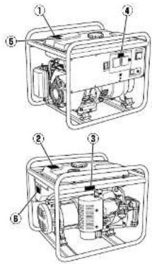
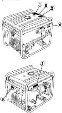
② EG601A, EG601AE
EG671A, EG671AE
②
③
EG241A, EG321A, EG321AE
EG441A, EG441AE

EG601A, EG601AE
EG671A, EG671AE
④
⑤
6
⑦
| EN | [appendix]Instructions for treatment as wasteWhen disposing this product, make sure that the fuel and oil should be drained from the engine ,and submit to local regulations. |
| FR | [Annexe]Instructions pour le traitement des dechetsQuand ce produit doit être mis au rebut, s'assurer que le carburant et l'huile ont été vidangés correctement à partir du moteur, et que les règlements locaux sont bien observés. |
| DE | [Anhang]Anweisungen für die Behandlung als AbfallBei der Entsorgung dieses Produkts sicherstellen, dass der Kraftstoff und das Öl aus dem Motor abgelassen wird und unter Befolgung akter örllich gülligen Bestimmungen entsorgt wird. |
| NL | [aanhangsel]Instructies voor afvalverwerkingWanneer u dit product weggooft, moet u ervoor zorgen dat alle brandistor en cile ut de motor verwijderd is en dient u zich te houden aan de ter plaatse geldence regelgeving. |
| ES | [anexo]Instruções para el tratamiento de los residuosCuando este producto debe ponerse al rechazo, asegurarse de que el combustible y el acele se purgaron correctamente a partir del motor, y que se observan bien los reglamentos locales. |
| IT | [appendix]Istruzioni per lo smaltimentoPer lo smaltimento di questo prodotto, assicurarsi di aspirare il carburante e folio dal motore,in conformità con le regolamentazioni locali. |
| PT | [apèndice]Instruções para tratamento como residuoQuando eliminar este produto, assegure-se de que o combustível e o óleo são escosados do motor e sujeitos às regulamentações locais. |
| GR | [Προσάρτημα]Οδηγίες για επεξεργασία ως απόβληταΌπαν απορούττετε αυτό το προλόν, βεβακωθείτε ότ τα καύσμα και τα λιπαντικά έχουν αδειάστεαπό τη μηχανή και τηρήσε τους τοπικούς κανονεμούς. |
| NO | [vedlegg]Instruksjoner for behandling av avfallNår dette produkt kasseres, må man påse at drivstarfet og oljen tommes tra motoren og behandles iføge lokale renovas,onsforskråter. |
| SE | [appendix]Anvlsningar för avfallshanteringNår denna produkt ska kasseras, se då till all bränslet och oljan lörns ur motorn, och all lokala bestämmøeler efterföjs. |
| FI | [LITE]Ohnita jätteirden käsittelemisestä |
5
②
③
EG441A, EG441AE
④
EG601A, EG601AE
EG671A, EG671AE
⑤
⑥
⑦

B
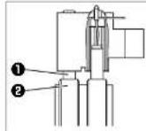
6
EN CE symbol label
FR Étiquette du symbole CE
DE ETIKETT für CE-Symbole
NL Etiket voor CE-symbolen
ES Etiqueta con el símbolo CE
IT Etichetta per simbolo CE
PT Etiqueta com o símbolo CE
GR Ετικέτα με το σύμβολο CE
NO CE-symbolmerke
SE CE-mHbrkeskilt
EL CE tunnustarra
DK 65 workskill
EG241A, EG321A, EG321AE
EG441A, EG441AE
EG601A, EG601AE
EG671A, EG671AE



EC- DECLARATION OF CONFORMITY
EG-KONFORMITATSERKLARUNG DÉCLARATION DE CONFORMITÉ "EC"
EU VERKLARING VAN CONFORMITEIT
EU-DEKLARATION OM KONFORMITET
| Manufacturer | Fabricante | MAKITA INTERNATIONAL EUROPE LTD. |
| Hersteller | Fabricante | Michigan Drive, Tongwell, Milton keynes, |
| Fabricant | Tilverkare | Bucks MK15 8JD, U.K. |
| Fabrikant | Valmistaja | |
| Costruttore | Produsent | |
| Katoakzeuostnig | Fabrikant |
Name and address of the person who keeps the Technical Documentation
Michigan Drive, Tongwell, Milton keynes,
Bucks MK15 8JD, U.K.
Tarnoyasu Kato Director
| Authorized Compiler In The CommunityAutolisterie Montagetansheimen in GebelComplator autorizare dans la CommuutadEntende varlagerwerderer in het rayenComplator autorizzato nella comunitàExclusivat om my Kowkinga perswaltung | Compiler autorizzato en la CommuotadComplator autorizzato na commuotadaAutoltersdammalsre im genutzigenPakstellinen adustajaAutoriset komputer i EUAutoriset computer i samfundet | MAKITA INTERNATIONAL EUROPE LTD.Michigan Drive, Tongwei, Milton keynes,Bucks MK15 8JD, U.K.Tamoyasu Kota Director |
The undersigned, 1. Kato, representing the manufacture, herewith declares that the product in conformity with the provisions
the following EC-directives;
Thank you very much for purchasing a MAKITA GENERATOR.
This manual covers operation and maintenance of the MAKITA GENERATOR.
This MAKITA GENERATOR can be used for general electrical equipments, appliances, lamps.
tools as an AC power source. With regards to DC application, the terminals are used only for
charging 12 volt battery.
Never use this generator for any other purposes.
Please take a moment to familiarize yourself with the proper operation and maintenance
procedures in order to maximize the sale and efficient use of this product
Keep this owner's manual at hand, so that you can refer to it at any time.
Due to constant efforts to improve our products, certain procedures and specifications are
subject to change without notice.

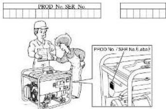
When ordering spare parts, always give us the MODEL, PRODUCTION NUMBER (PROD No.)
and SERIAL NUMBER (SER No.) of your Product.
Please sill in the following blanks after checking the production number on your product.
(Location of label is different depending on the product model.)
CONTENTS
Page
- SAFETY PRECAUTIONS 2
- COMPONENTS....5
- PRE-OPERATION CHECKS....5
- OPERATING PROCEDURES 7
- WATTAGE INFORMATION....11
- SPARK ARRESTER 12
- MAINTENANCE SCHEDULE 13
- "HOW-TO" MAINTENANCE ....14
- PERIODIC OPERATION AND INSPECTION....15
- TRANSPORTING 15
- PREPARATION FOR STORAGE 16
1. SAFETY PRECAUTIONS
Please make sure you review each precaution carefully.
Pay special attention to statement preceded by the following words.

"WARNING" indicates a strong possibility of severe personal injury or loss of life if instructions are not followed.

"CAUTION" indicates a possibility of personal injury or equipment damage if instructions are not followed.

Do not operate the generator near gasoline or gaseous fuel because of the potential danger of explosion or fire.
Do not fill the fuel tank with fuel while the engine is running. Do not smoke or use open all amo near the fuel tank. Be careful not to spill fuel during refueling.
If fuel is spilt, wipe it off and let dry before starting the engine

Do not place in 4 ammables near the generator.
Be careful not to place fuel, matches, gunpowder, oily cloths, straw, trash, or any other in a emmibles near the generator.

Do not operate the generator inside a room, cave, tunnel, or other insufficiently ventilated area.
Always operate it in a well-ventilated area, otherwise the engine may become overheated, and the poisonous carbon monoxide gas, an odorless, colorless, poison gas, contained in the exhaust gas will endanger human lives.
Operate generator only outdoors and far from open windows, doors, ventilation intakes and other openings.
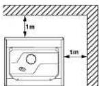
Keep the generator at least 1 meter (3 feet) away, including overhead, from any structure or building use.

Do not enclose the generator nor cover it with a box.
The generator has a built-in forced air cooling system, and may become overested if it is enclosed.
If generator has been covered to protect it from the weather during non use, be sure to remove it and keep it well away from the area during generator use.

Operate the generator on a level surface.
It is not necessary to prepare a special foundation for the generalot.
However, the generator will vibrate on an irregular surface, so choose a level place without surface irregularities.
If the generator is tilted or moved during operation, fuel may spill and / or the generator may tip over, causing a hazardous situation.
Proper lubrication cannot be expected if the generator is operated on a steep incline or slope. In such a case,



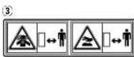
WARNING
Do not operate in rain, in wet or damp conditions, or with wet hands.
The operator may suffer severe electric shock if the generator is wet due to rain or snow
WARNING
If wet, wipe and dry it well before starting. Do not pour water directly over the generator, nor wash it with water.
WARNING
Be extremely careful that all necessary electrical grounding procedures are followed during each and every use. Failure to do so can be fatal.
WARNING
Do not contact the generator to a commercial power line. Connection to a commercial power line may short circuit the generator and ruin it or cause electric shock hazard. Use the transfer switch for connecting to domestic circuit.
WARNING
No smoking while handling the battery. The battery emits flammable hydrogen gas, which can explode if exposed to electric arcing or open flame. Keep the area well-ventilated and keep open names/sparks away when handling the battery.
WARNING
Engine becomes extremely hot during and for some time after operation. Keep combustible materials well away from generator area. Be very careful not to touch any parts of the hot engine especially the matter area or serious burns may result.
WARNING
Keep children and all bystanders at a safe distance from work areas.
WARNING
It is absolutely essential that you know the safe and proper use of the power tool or appliance that you intend to use. All operators must read, understand and follow the tool/appliance owners manual. Tool and appliance applications and limitations must be understood. Follow all directions given on labels and warnings. Keep all instruction manuals and literature in a safe place for future reference.
WARNING
Use only "LISTED" extension cords. When a tool or appliance is used outdoors, use only extension cords marked "For Outdoor Use". Extension cords, when not in use should be stored in a dry and well ventilated area.
WARNING


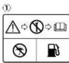
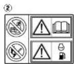
Symbols and Meanings
In accordance with the European requirements (eeC Directives), the specified symbols as shown in the following table are used for the products and this instruction manual.
| Read the operator's instruction manual. | Fire, open light and smoking prohibited. | ||
| Stay clear of the hot surface. | Do not connect the generator to the commercial power lines. | ||
| Exhaust gas is poisonous.Do not operate in an unventilated room. | Do not operate in rain or snow. | ||
| Stop the engine before refueling. | Call for maintenance. | ||
| Caution, risk of electric shock. | Keep dry. | ||
| HOT, avoid touching the hot area. |
| ON(power and Engine) | IN-position of a bistable push control | Engine start(Electric start) | |||
| OFF(power and Engine) | Protective earth(ground) | Engine stop | |||
| Alternating current | Fuse | Gasoline | |||
| Direct current | Engine oil | Fast | |||
| Plus;positive polarity | Add oil | Slow | |||
| Minus;negative polarity | Battery chargingcondition | Fuel start / Open | |||
| OUT-position of a bistable push control | Choke;cold starting aid | Fuel stop / Close |
| P_r | Rated power (kW) | COP | Continuous power | _r | Rated power factor |
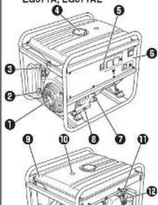
2. COMPONENTS 3. PRE-OPERATION CHECKS
(See Fig. 1) (See Fig. 2)
NOTE
Please refer to the illustrations on the back page of the front cover or back cover for Fig.1 to 6 indicated in the sentence.
EG241A, EG321A, EG321AE,
EG441A, EG441AE (See Fig. 1-①)
RECOIL STARTER
② RECOIL STARTER HANDLE
③ FUEL STRAINER (FUEL VALVE)
FUEL TANK
⑤ ENGINE SWITCH
6 CONTROL PANEL
⑦ OIL GAUGE (OIL FILLER)
⑧ OIL DRAIN PLUG
⑨ FUEL GAUGE
TANK CAP
⑪ SPARK PLUG CAP
CHOKE LEVER
AIR CLEANER
EXHAUST OUTLET
MUFFLER COVER
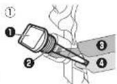
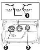
- CHECK ENGINE OIL (See Fig. 2-①,②)
Before checking or ret. lling oil, be sure generator is located on stable and level surface with engine stopped.
Remove oil filler cap and check the engine oil level.
(Scc Fig.12-1)
① OIL GAUGE
② OIL FILLER
6 UPPER LEVEL
LOWER LEVEL
Oil level is below the lower level line, re:ll with
suitable oil (see table) to upper level line. Do not
Screw in the oil offer cap when checking of level
(2017年1月1日)
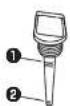
UPPER LEVEL
② LOWER LEVEL
●change oil if contaminated.
(See "How-To" Maintenance.)
| Oil capacity (Upper level) : (L) |
| EG241A | 0.6 |
| EG321A, EG321AE | 0.6 |
| EG441A, EG441AE | 1.0 |
| EG001A, EG001AE | 1.2 |
| EG071A, EG071AE | 1.8 |
Recommended engine oil:
Use 4-stroke automotive detergent oil of API service class
SE or highergrade (SG, SH or SJ is recommended).
SAE TOW-30 of TOW-40 is recommended for general, all temporary use.
If single viscosity oil
viscosity for the average temperature in your area.
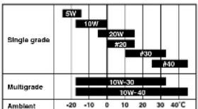
bar
| Condition | Temperature (°C) | |---|---| | Single grade | 5W | | Single grade | 10W | | Single grade | 20W | | Single grade | #20 | | Single grade | #30 | | Single grade | #40 | | Multigrade | 10W-30 | | Multigrade | 10W-40 | | Ambient | -20 to 40°C |2. CHECK ENGINE FUEL (See Fig. 2-3,4)
WARNING
Do not refuel while smoking or near open £1 ame or other such potential £1 re hazards. Otherwise £1 re accident may occur.
- check fuel level at fuel level gauge (See Fig.12-3)
■ fuel level is low, refill with unleaded automotive gasoline.
Be sure to use the fuel after screen on the fuel after neck. (See Fig.2-4)
LEVEL
FUEL TANK CAP
③ FUEL FILTER SCREEN
Fuel Amount
up to "LEVEL" position : (L)
| EG241A | 12.8 |
| EG321A, EG321AE | 12.8 |
| EG441A, EG441AE | 12.8 |
| EG601A, EG601AE | 22.0 |
| EG671A, EG671AE | 22.0 |
WARNING
Make sure you review each warning in order to prevent fire hazard.
Do not ren II tank while engine is running or hot.
●lose fuel cock before refueling with fuel.
■e careful not to admit dust, dirt, water or other foreign objects into fuel.
Wipe off split fuel thoroughly before starting engine.
Keep open dames away.
3. CHECKING COMPONENT PARTS
Check following items before starting engine:
■Fruit looking from fruit hope, etc.
4. CHECK GENERATOR SURROUNDINGS
WARNING
Make sure you review each warning in order to prevent a re hazard.
Keep area clear of in a immables or other hazardous materials.
- Keep generator at least 3 feet (1 meter) away from buildings or other structures.
■Only operate generator in a dry, well ventilated area.
- Keep exhaust pipe clear of foreign objects.
Keep generator away from open a ame. No smoking!
- Keep generator on a stable and level surface.
- Do not block generator air vents with paper or other material.
5. GROUNDING THE GENERATOR
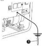
■To ground the generator to the earth, connect the grounding lug of the generator to the grounding spike driven into the earth or to the conductor which has been already grounded to the earth. (See Fig.2-1)
① GROUNDING SPIKE
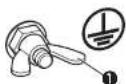
such grounding conductor or grounding electrode is unavailable, connect the grounding lug of the generator to the grounding terminal of the using electric tool or appliance. (See Fig.21-10)
① GROUND TERMINAL
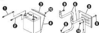
6. BATTERY INSTALLATION (See Fig. 2-7)
(Electric Starter Model)
Recommended Battery
Type : Lead-acid battery
Capacity
(Ah5hr) ; 12V-21AH or more
Size ; Less than 165(L) x 125(W) x 160(H) Min
EARTH CABLE(BLACK)
STARTER CABLE(RED)
③ SETTING PLATE
SETTING BOLT
•
WARNING
Death, personal injury and/or property damage may occur unless instructions are followed carefully.
Use battery of recommended capacity.
Turn the starter switch to the "O" (STOP)
position when mounting or dismounting
batterly: when mounting battery, connect the positive (+) cable rust and then the negative
(-) cable to the battery. Be careful not to
short battery cables. When dismounting
battery, disconnect negative (-) cable & rst.
RED CABLE : To positive (+) terminal BLACK CABLE : To negative (-) termi
BEAR CABLE TO negative ( ) terminal Should the connection be made in incorrect
Should the connection be made in incorrect manner, the generator will be broken.
Tighten bolts and puts on terminals securely
so they will not be loosened by vibration.
■Disconnect battery cables when charging
battery.
4. OPERATING PROCEDURES
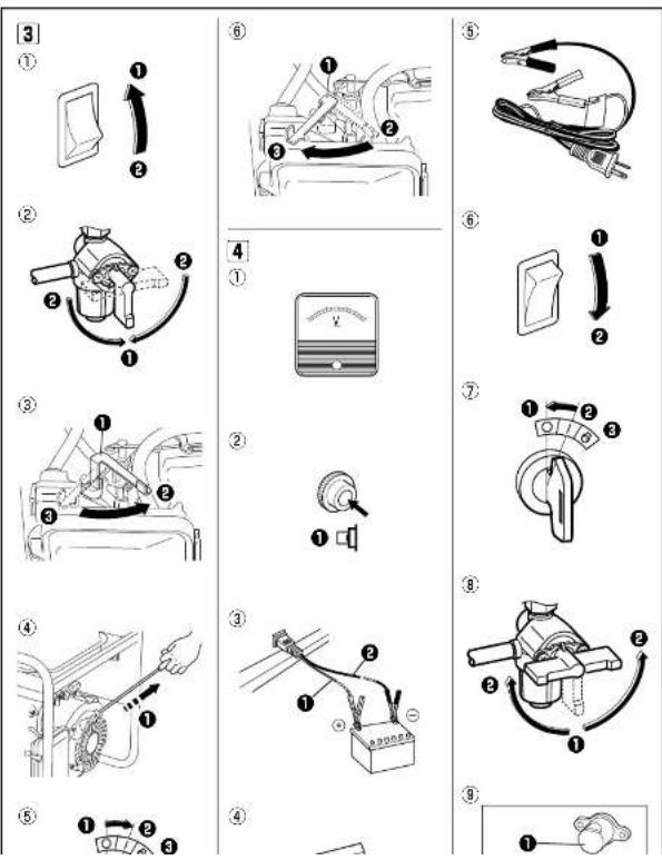
(See Fig. 3)
- STARTING THE GENERATOR
CAUTION
Check the oil level before each operations as
outlined by the article "CHECK ENGINE OIL"
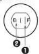
(a) Turn the Engine switch to the position " | " (ON).
(See Fig.3-1)
①* | ^ (ON)
② O (OFF)
(b) Open the fuel valve. (See Fig.3)-(2)
① OPEN
CLOSE
(c) Set choke lever to close if the engine is cold.
(Soc Fig. 3)-(3)
① CHOKE LEVER
Pull the starter handle slowly until passing the
compression point (resistance will be felt), then
return the handle to its original position
and pull briefly. (See Fig.2-4)
① PULL BRISKLY
the engine fails to start after several attempts,
repeat above procedures with choke lever returned
to "OPEN" position.
Do not fully pull out the rope.
After starting, allow the starter handle to return to
its original position while still holding the handle.
(e) [Electric starter model]
Insert the key into the key switch and turn it
clockwise to the *|* (RUN) position to start the
engine.
Then turn the key further to the “○” (START)
position.
The engine will be started by starting motor.
(See Fig.3-⑧)
① "O" (STOP)
② " | "(RUN)
3 (START)

CAUTION
■o not run the starting motor over 5 seconds
continuously.
If the engine falls to start, return the key to the "I" (RUN) position and wait about 10
the 1 (HON) position and wait about to seconds then start again
■o not turn the key switch to “ ” (START)
position when the engine is running to
prevent damage of starting motor.
When starting the engine by recoil starter,
set the key switch at the "I" (RUN) position
and pull the starter handle.
(1) After the engine started, return the choke lever
gradually to "OPEN" position.
(Soc Fig.3-6)
① CHOKE LEVER
② CLOSE
③ OPEN
2. USING ELECTRIC POWER
WARNING
Make sure that the appliance is switched OFF before connecting it to the generator.
■ Do not move the generator while it is running.
Be sure to ground the generator if the connected appliance is grounded. Failure to ground unit may lead to electrical shock.
CONTROL PANEL

(EG241A, EG321A, EG321AE)
![[Electric starter model] Key switch Engine switch AC receptacle 20A AC circuit breaker Volt meter DC circuit breaker Earth (ground) terminal DC receptacle](/content/2026/05/924927/images/b027732d62b5fd97951cde02c129f569cafebc002609915b0022053529f3dad7.jpg)
(EG441A, EG441AE, EG601A, EG601AE, EG671A, EG671AE)
![[Electric starter model] Key switch Engine switch AC receptacle 20A AC circuit breaker Volt meter DC circuit breaker Earth (ground) terminal DC receptacle](/content/2026/05/924927/images/535b52f162a0c2c473a5ba5f5726813fb57359d26561e82ab41674057b9ad658.jpg)
(1) AC APPLICATION
(a) Check the voltmeter for proper voltage. (See Fig.4-1)
This generator is thoroughly tested and adjusted in the factory.
If the generator does not produce the specified voltage, consult your nearest Makila factory or authorized service center.
(b) Turn off the switch (os) of the electrical appliance (s) before connecting to the generator.
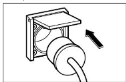
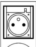
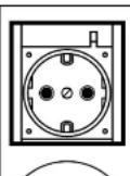
(c) Insert the plug (s) of the electrical appliance(s) into the receptacle.
natural_image
Diagram of a cable or plug assembly with a directional arrow indicating movement (no text or symbols present)Check the amperage of the roeoptacles, and be sure not to take a current exceeding the specified amperage.
Be sure that the total wattage of all appliances dose not exceed the rated output of the generator.
CAUTION
Do not put foreign objects into the plug receptacle.
WARNING
Be sure to ground the generator if the connected electrical device is grounded.
NOTE
When the AC circuit breaker turns off during operation, the generator is over loaded or the appliance is defective.
Stop the generator immediately, check the appliance and / or generator for overloading or detect and have repaired as necessary by Makita factory or authorized service center.
(d) Check and confirm whether circuit breaker position is I (ON). (See Fig.4-2)
① “|”(ON)
(c) Turn on the switch of the appliance.
(2) DC APPLICATION
(Only for charging 12 volt battery)
DC receptacle (Only for charging 12 volt battery) (See Fig.4)-(3)
① RED CABLE
BLACK CABLE
For charging 12 voltage battery, 12V-8.3A (100W) of maximum AC power can be taken out from the DC receptacle by means of the exclusive DC cable. (See Fig.4)④
The exclusive DC cable is come with your generator set (included in the package) (See Fig.4-5).
DC Circuit Breaker
DC circuit breaker is turned off to shut down the DC power, when the DC is over the usage range or the battery is defective.
Check the generator and/or battery for overloading or defect, and turn on the DC circuit breaker after no problem and defect are found out.
Connection of exclusive DC cable :
EN
Battery Charging Procedures :
1) Stop engine
2) Remove all connections from battery.
3) Insert the plug of exclusive DC cable into DC
receptacle.
4) Connect positive (red) clip of DC cable to positive (+) terminal on battery, and then connect negative (black) clip of DC cable to negative (-) terminal on battery.
5) Take out all plugs at the battery electrolyte fluid still ports.
6) Check the electrolyte fluid level, and roll the distilled water as necessary.
71 Start engine.
B) Make sure that the pilot lamp is turned on.
9) Make sure that the DC circuit breaker is in the ON position.
10) Battery charging will be started.
CAUTION
- Do not use both AC and DC output at the same time.
Install correct positive (red) or negative (black) cable to the correct polarity on the battery.
Connect and disconnect DC cable with engine stopped.
An explosive hydrogen gas is discharged through vent holes in the battery during the charging process.
Do not allow spark or open a time around the generator or battery during the charging process.
Electrolyte n uid contains sulphuric acid, and so the n uid can burn eyes and clothing. Be extremely careful to avoid contact. If injured, wash the affected area immediately with large quantities of water and consult a doctor for treatment.
Charging time is varied according to the kind of battery and discharged level of battery. Measure the specific gravity of electrolyte fluid by means of hydrometer every one hour during battery charging.
Make sure if the DC circuit breaker is not turned off.
Onshore chauvins is completed when the
3. STOPPING THE GENERATOR
(a) Turn off the power switch of the electric equipment and unplug the cord from receptacle of the generator.
(b) Allow the engine about 3 minutes to cool down at no-load before stopping.
(c) [Recoil starter model]
Turn the engine switch to the position * O * (OFF) (See Fig. 4-10)
① " | " (ON)
② "O" (OFF)
[Electric starter model]
Turn the key switch to the STOP position.
(See Fig. 4)-(7)
① "O" (STOP)
② " | " (RUN)
6" (START)
4. OIL SENSOR (See Fig. 4-8)
① OIL SENSOR
(a) The oil sensor detects the fall in oil level in the crankcase and automatically stops the engine when the oil level falls below a predetermined level.
(b) When engine has stopped automatically, switch off generator's AC circuit breaker, and check the oil level.
Red II engine oil to the upper level as instructed on page 5 and restart the engine.
(c) If the engine does not start by usual starting procedures, check the oil level.
5. WATTAGE INFORMATION
Some appliances need a "surge" of energy when starting.
This means that the amount of electrical power needed to start the appliance may exceed the amount needed to maintain its use.
Electrical appliances and tools normally come with a label indicating voltage, cycles / Hz, amperage (amps) and electrical power needed to run the appliance or tool.
Check with your nearest dealer or service center with questions regarding power surge of certain appliances or power tools.
Electrical loads such as incandescent lamps and hot plates require the same wallage to start as is needed to maintain use.
loads such as fluorescent lamps require 1.2 to 2 times the indicated wattage during start-up.
loads for mercury lamps require 2 to 3 times the indicated wallage during start-up.
Electrical motors require a large starting current. Power requirements depend on the type of motor and its use.
Once enough "surge" is attained to start the motor,
the appliance will require only 50% to 30% of the wattage to continue running.
Most electrical tools require 1.2 to 3 times their voltage for running under load during use. For example, a
5,000 watt generator can power a 1800 to 4000 watt electrical tool.
loads such as submersible pumps and air compressors require a very large force to start. They need 3 to 5
times the normal running wattage in order to start.
For example, a 5,000 watt generator would only be able to drive a 1,000 to 1,700 watt pump.
NOTE
The following wattage chart is general guide only. Refer to your specific appliance for correct wattage.
To determine the total wallage required to run a particular electrical appliance or tool, multiply the voltage figure of the appliance/tool by the amperage (amps) figure of same. The voltage and amperage (amps) information can be found on a name plate which is normally attached to electrical appliances and tools.
| Applications | Applicable Wattage(W) | ||||
| EG241A | EG321A EG321AE | EG441A EG441AE | EG601A EG601AE | EG671A EG671AE | |
| Incandescent lamp, Heater 2000 2400 | 3000 4600 | 5500 | |||
| Fluorescent lamp, Electric tool 1100 | 1300 2000 25 | 50 3050 | |||
| Mercury lamp 800 950 1450 1650 | 2200 | ||||
| Pump, Compressor 500 600 900 | 150 1430 | ||||
VOLTAGE DROP IN ELECTRIC EXTENSION CORDS
When a long electric extension cord is used to connect an appliance or tool to the generator, a certain amount of voltage drop or loss occurs in the extension cord which reduces the effective voltage available for the appliance or tool. The chart below has been prepared to illustrate the approximate voltage loss when an extension cord of 300 feet (approx. 100 meters) is used to connect an appliance or tool to the generator.
| Nominal cross section | A.W.G. | Allowable current | No.of strands / strands dia. | Resistance | Current Amp. | ||||||
| mm^2 | No. A No./mm | /100cm 1 | A 3A | 5A 8A | 0A 12 | A 15A | |||||
| 0.75 | 13 | 7 | 30V 18 | 2.477 | 2.5V | 8V | 13.5V | — | — | — | — |
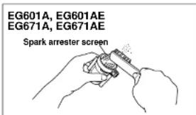
6. SPARK ARRESTER
In a dry or wooded area, it is recommendable to use the product with a spark arrester. Some areas require the use of a spark arrester. Please check your local laws and regulations before operating your product.
The spark arrester must be cleaned regularly to keep it functioning as designed.
A clogged spark arrester
●Prevents the flow of exhaust gas
• Reduces engine
• Increases fuel consumption
■Makes starting difficult cult
If the engine has been running, the muffler and the spark arrester will be very hot. Allow the muffler to cool before cleaning the spark arrester.

How to remove the spark arrester
- Remove the range bolts from the muffor cover and remove the muffor cover.
- Remove the special screw from the spark arrester and remove the spark arrester from the multi er.
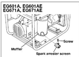
Clean the spark arrester screen
Use a brush to remove carbon deposits from the spark arrester screen.
Be careful to avoid damaging the screen.
The spark arrester must be free of breaks and holds. Replace the spark arrester if it is damaged, install the spark arrester, and multi-er protector in the reverse order of disassembly.
- MAINTENANCE SCHEDULE
| DAILY | check oil level shock all components according to "PRE-OPERATION CHECKS." |
| EVERY 50 HOURS | Wash cleaner element, more often if used in dirty or dusty environments. shock spark plug, clean if necessary. |
| EVERY 100 HOURS | change engine oil, "more often if used in dusty or dirty environments. clean spark arrester. |
| EVERY 200 HOURS | Adjust spark plug gap. clean fuel strainer. |
| EVERY 500 HOURS | replace spark plug and cleaner element. clean and adjust carburetor, valve clearance, and valve seat along with cylinder head. shock and replace carbon brushes |
| EVERY 1,000 HOURS (24 MONTHS) | respect control panel parts. check rotor and starter. replace engine mount rubber. overhaul engine. change fuel lines. |
EN
NOTE : (\*)
Initial oil change should be performed after first twenty (20) hours of use. Thereafter change oil every 100 hours.
Before changing the oil, check for a suitable way to dispose of the old oil.
Do not pour it down sewage drains, onto garden soil or into open streams.
Your local zoning or environmental regulations will give you more detailed instructions on proper disposal.
8. "HOW-TO" MAINTENANCE
CAUTION
Make sure the engine is stopped before starting any maintenance, servicing or repair.
NOTE
It is recommended to use ear protection when performing operation, maintenance and repair of the generator set.
EN
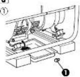
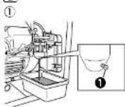
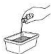
ENGINE OIL CHANGE (See Fig. 5-①)
●change engine oil every 100 hours. (For new engine, change oil after 20 hours.)
(a) Drain oil by removing the drain plug and the oil filler cap while the engine is warm.
① OIL DRAIN PLUG
(b) Reinstall the drain plug and fill the engine with oil until it reaches the upper level on the oil filler cap.
Use fresh and high quality lubricating oil to the specified level as directed on page 5. If contaminated or deteriorated oil is used or the quantity of the engine oil is not sufficient, the engine damage will result and its life will be greatly shortened.
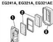
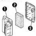
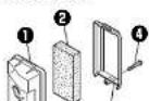
SERVICING THE AIR CLEANER
(See Fig. 5-② thru ④)
Maintaining an air cleaner in proper condition is very important.
Dirt induced through improperly installed, improperly serviced or inadequate elements damages and wears out engines. Keep the element always clean.
① BASE
ELEMENT
AIR CLEANER COVER
BOLT
(a) Remove the bolt of air cleaner cover
(EG601A, EG601AE, EG671A, EG671AE) (See Fig.[5]-④)
Remove the air cleaner cover and cleaner element.
NOTE
Instead of washing oil (kerosene). It is possible to wash the urethane foam element in a solution of mild detergent and warm water.
Then rinse the element thoroughly in clean water. Allow the element to dry thoroughly. Soak the element in clean engine oil and squeeze out excess oil.
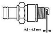
CLEANING AND ADJUSTING SPARK PLUG (See Fig. 15-6)
(a) If the plug is contaminated with carbon, remove it using a plug cleaner or wire brush.
(b) Adjust the electrode gap to 0.6 to 0.7 mm.
Spark plug : BR-6HS (NGK)
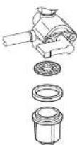
CLEANING FUEL STRAINER
(See Fig. 5-6)
Dirt and water in the fuel are removed by the fuel strainer.
(a) Remove the strainer cup and throw away water and dirt.
(b) Clean the screen and strainer cup with gasoline.
(c) Tightly fasten the cup to main body, making sure to avoid fuel leak.
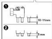
CHECKING CARBON BRUSH
Brush Maintenance Essentials (Effective Length)
The brush is the area which touches the slip ring, and its surface must be kept smooth.
If it is not smooth then carbon and other substances will adhere between the brush and slip ring.
This must be buffed with sandpaper or the like because it is hazardous.
The usable length of the brush is 5-11mm, so if the brush is 5mm long or loss replace it with a new one.
This is done because if the length of the brush gets any shorter, its contact pressure with the slip ring will decrease, resulting in a drop in generator efficiency and the output voltage.
Check the brush every 500 hours to confirm its length.
In addition, check the brush length if the generator malfunctions, such as when it is not generating power or its voltage is low.
Brush Maintenance Essentials
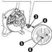
(Disassembly and Assembly) (See Fig. 5-8)
1 BRUSH
② SLIP RING
③ BRUSH HOLDER
FLANGE BOLTS
⑤ BRACKET COVER
⑥ FLANGE BOLTS
Disassembly
- Remove the two □ ange bolts (M5 x 20), then remove the bracket cover.
- Remove the two orange bolts (M5 x 16), then remove the brush.
Assembly
- While pressing the brush against the slip ring, secure it (1.5-2N+m) by tightening it with the two flange bolts (M5 × 18). When doing so, cord rm that the brush is in the proper position relative to the slip ring.
- Secure the bracket cover (3-4N·m) by tightening it with the two flange bolts (M5 × 20).
9. PERIODIC OPERATION AND INSPECTION
When furnishing the generator as emergency electric power source, periodic operation and inspection are needed.
Fuel (gasoline) and engine oil will be deteriorated with time, and this causes that the engine is difficult to start and as the results improper engine operation and fault.
(a) Check the fuel (gasoline), engine oil and air
cleaner.
(b) Start engine.
(c) With appliance such as lightings activated, run the engine for over ten minutes.
(d) Check for the following items:
Proper engine running.
Adequate output and the indicator lamp turned on properly.
The engine switch normally operated
No leakage of engine oil and fuel (gasoline).
10. TRANSPORTING
When transporting the generator, make sure that the fuel (gasoline) should be drained from the tank.
WARNING
To prevent fuel spillage due to the vibration and impact, never transport the generator with the fuel (gasoline) is led in the tank.
Secure the tank cap thoroughly.
To avoid the risk of the gasoline a immability, never leave the generator in an area exposed to direct sunlight or high temperatures for a long time.
Keep the fuel (gasoline) in the exclusive gasoline storage tank made by steel whe transporting.
(a) Turn the engine switch to the "STOP" position.
(b) Drain the fuel from the tank.
(c) Secure the tank cap.
CAUTION
Do not place any heavy objects on the generator.
Select and place the generator in the proper
11. PREPARATION FOR STORAGE
(See Fig. 6)
The following procedures should be followed prior to storage of your generator for periods of 6 months or longer.
- Drain fuel from fuel tank carefully by disconnecting the fuel line.
Gasoline left in the fuel tank will eventually deteriorate making engine-starting difficult.
Remove the carburetor real chamber and also drain the carburetor. (See Fig.8-1)
① DRAIN SCREW
- charge engine oil.
- check for loose bolts and screws, tighten them if necessary.
●lean generator thoroughly with oiled cloth.
Spray with preservative if available
NEVER USE WATER TO CLEAN GENERATOR!
■full starter handle until resistance is felt, leaving handle in that position.
Store generator in a well ventilated, low humidity area.
12. TROUBLESHOOTING
When generator engine fails to start after several attempts, or if no electricity is available at the output socket, check the following chart. If your generator still fails to start or generate electricity, contact your nearest Makita factory or authorized service center for further information or corrective procedures.
When Engine Fails to Start:
| Check if choke lever is in its proper position. Set the choke lever to "CLOSE" position. | |
| Check if fuel valve is open. | If closed, open fuel valve. |
| Check fuel level. | If empty, refill fuel tank making sure not to overfill. |
| Check if engine switch is in OFF. Turn engine switch to ON. | |
| Check to make sure generator is not connected to an appliance. | If connected, turn off the power switch on the connected appliance and unplug. |
| Check spark plug for loose spark plug cap. | If loose, push spark plug cap back into place. |
| Check spark plug for contamination. Remove spark plug and clean electrode. | |
When No Electricity Is Generated at Receptacle:
| Check to make sure AC circuit breaker is in the "ON" position. | After making sure that the total wafage of the electrical appliance is within permissible limits and there are no defects in the appliance, turn the AC circuit breaker to the "ON" position.If breakers continue to actuate, consult your nearest servicing dealer. |
- SPECIFICATIONS
| MODEL EG241A | EG321A EG321AE | EG441A EG441AE | EG601A EG601AE | EG671A EG671AE | ||
| Generator | Type Brush, soft-occurring, 2-polts, single phase | |||||
| Voltage regulating system AVR type | ||||||
| AC Output | ||||||
| Rated voltage-Frequency V-Hz 230 - 50 | ||||||
| Rated current A 8.7 10.4 15.7 20.0 23.9 | ||||||
| Rated output VA (W) 2000 2400 3600 4600 5500 | ||||||
| Maximum output VA (W) 2400 3200 | 4400 6000 6700 | |||||
| Rated power factor 1.0 | ||||||
| Safety device type Fuse less circuit breaker | ||||||
| DC Output | ||||||
| Rated voltage V | 12 | |||||
| Rated current A | 8.3 | |||||
| Safety device type Fuse less circuit breaker | ||||||
| Engine | Model | EX17D | EX21D | EX30D | EX35D | EX40D |
| Type | ROBIN. Air-cooled, 4-stroke, OHC, Gasoline Engine | |||||
| Displacement mL | 169 211 | 287 | 404 | |||
| Fuel | Automotive Unleaded Gasoline | |||||
| Fuel tank capacity L | 12.8 | 22.0 | ||||
| Engine oil capacity L | 0.6 | 1.0 | 1.2 | |||
| Rated continuous operation H | 10.5 | 9.0 | 5.6 | 7.5 | 8.6 | |
| Spark plug | BRI-BHS (NGK) | |||||
| Starting system | Recoil starter | Electric stiner / Recoil | ||||
| 3/4 Load Fuel consumption L/H | 1.0 | 1.3 | 1.9 | 2.7 | 2.9 | |
| Direction of rotation | Counter-clockwise | |||||
| Dimension | Length mm | 650 | 620(870)*1 | 675(925)*1 | 725(975)*1 | |
| Width mm | 420 450 | 510 | 530 | |||
| Height mm | 500 500 | 540 | 580 | |||
| Dry weight kg | 47 | 51(56)*2 | 67(77)*2 | 86(96)*2 | 88(98)*2 | |
EN
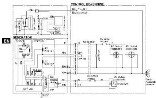
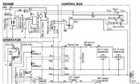
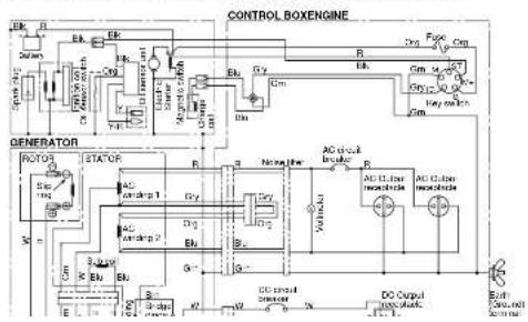
14. WIRING DIAGRAM
EG241A, EG321A (50Hz-230V) [Recoll starter model]
flowchart
graph TD
    A["GENERATOR"] --> B["Motor"]
    B --> C["STATOR"]
    C --> D["AC circuit"]
    D --> E["AC output"]
    E --> F["DC output"]
    F --> G["DC Input"]
    G --> H["Control Box Engine"]
    style A fill:#f9f,stroke:#333
    style B fill:#ccf,stroke:#333
    style C fill:#cfc,stroke:#333
    style D fill:#fcc,stroke:#333
    style E fill:#cff,stroke:#333
    style F fill:#ffc,stroke:#333
    style G fill:#cfc,stroke:#333
    style H fill:#fcc,stroke:#333
Wiring color code
例:11.4.6
5.10.2013
图 1
Bull, Biscu
lmV : IbenVth is
gm : Green
CHW. CHINWEI
附:
City - 047
- P#
K. Yolby
4121: dNwFlock
(1) 2017年1月1日
Dr. A. F. pole
EG321AE (50Hz-230V) [Electric starter model]
flowchart
graph TD
    A["GENERATOR"] --> B["POWER"]
    B --> C["AC driving 1"]
    B --> D["AC driving 2"]
    B --> E["AC drive 3"]
    B --> F["AC drive 4"]
    B --> G["AC drive 5"]
    B --> H["AC drive 6"]
    B --> I["AC drive 7"]
    B --> J["AC drive 8"]
    B --> K["AC drive 9"]
    B --> L["AC drive 10"]
    B --> M["AC drive 11"]
    B --> N["AC drive 12"]
    B --> O["AC drive 13"]
    B --> P["AC drive 14"]
    B --> Q["AC drive 15"]
    B --> R["AC drive 16"]
    B --> S["AC drive 17"]
    B --> T["AC drive 18"]
    B --> U["AC drive 19"]
    B --> V["AC drive 20"]
    B --> W["AC drive 21"]
    B --> X["AC drive 22"]
    B --> Y["AC drive 23"]
    B --> Z["AC drive 24"]
    B --> AA["AC drive 25"]
    B --> AB["AC drive 26"]
    B --> AC["AC drive 27"]
    B --> AD["AC drive 28"]
    B --> AE["AC drive 29"]
    B --> AF["AC drive 30"]
    B --> AG["AC drive 31"]
    B --> AH["AC drive 32"]
    B --> AI["AC drive 33"]
    B --> AJ["AC drive 34"]
    B --> AK["AC drive 35"]
    B --> AL["AC drive 36"]
    B --> AM["AC drive 37"]
    B --> AN["AC drive 38"]
    B --> AO["AC drive 39"]
    B --> AP["AC drive 40"]
    B --> AQ["AC drive 41"]
    B --> AR["AC drive 42"]
    B --> AS["AC drive 43"]
    B --> AT["AC drive 44"]
    B --> AU["AC drive 45"]
    B --> AV["AC drive 46"]
    B --> AW["AC drive 47"]
    B --> AX["AC drive 48"]
    B --> AY["AC drive 49"]
    B --> AZ["AC drive 50"]
Wiring color code
BK : B125
Eli · Run
LS:Lightwave
Em : BWA
BOM. BOANHO
G: (A: G###)
Cig Charges
Gy : Grey
- 1954
Y: Yellow
Wilk: "Nordilluck"
GIMY: GreenYellow
(1) 2017年

EG441AE, EG601AE, EG671AE (50Hz-230V) [Electric starter model]
flowchart
graph TD
    A["Generator"] --> B["Motor"]
    B --> C["STATOR"]
    C --> D["Control Box Engine"]
    D --> E["Power"]
    D --> F["Current"]
    D --> G["Voltage"]
    E --> H["AC Motor"]
    F --> I["AC Current"]
    G --> J["DC Output"]
    H --> K["AC Motor + 1"]
    I --> L["AC Motor + 2"]
    J --> M["DC Motor + 3"]
    K --> N["Output"]
    L --> O["Output"]
    M --> P["Output"]
15. OPTIONAL PARTS
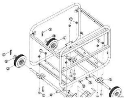
Wheel Kit Installation
(1) Check the supplied accessories
(2) Tool preparation
Drane or square bar (about 100mm by 100mm)
Plicor
2 sets of spanners (12mm)
(3) Installation procedures

A) Raise the generator about 100mm with the crane or square bar.
3) Install the wheel and stopper in the wheel shaft.
Install wheel shaft ⑤ into stopper ① so that wheel ② is inserted between them and fasten with pin ③.
Next, tighten wheel shaft ⑤ and stopper ① with nut ④.
Install wheel ② and washer ⑩ onto wheel shaft ⑪ and fasten with pin ⑫.
) Check that the wheel rotates smoothly.
1) Lopsen length adjustment nut (8) for wheel shaft (5) and bolt (10), then align the position of the hole on the
frame with the mounting hole of wheel shaft (1) and tighten bolt (2) and nut (3) to fix this in place.
Tightening torque: 20 to 25N·m (2.0 to 2.5kg·m)
E) Tighten length adjustment nut (2) for wheel shaft (6) and bolt (10) to fix the length of wheel shaft (5).
VOORWOORD
INHOUD
Bladzijde
-
VEILIGHEIDSMAATREGELEN....2
-
COMPONENTEN 5
-
CONTROLES VOOR HET IN WERKING STELLEN....5
-
BEDIENINGSPROCEDURES ....7
-
INFORMATIE OVER HET VERMOGEN....11
-
VONKENVANGER 12
-
ONDERHOUDSSCHEMA....13
-
ZELF UIT TE VOEREN ONDERHOUD....14
-
PERIODIEKE HANDELINGEN EN INSPECTIES....15
-
VERVOER....15
-
VOORBEREIDINGEN VOOR OPSLAG 16
-
OBLIGOVYAN BROBISHEN
1. VEILIGHEIDSMAATREGELEN
(Ah5hr) ; 12V-21AH of meer
Afmotingen ; Minder dan 185(L) x 125(W) x 160(H) mm
AARDINGSKABEL (ZWART)
2 STARTKABEL (ROOD)
⑨ INSTELPLAAT
INSTELBOUT
WAARSCHUWING
① * | * (AAN) ② * ○ * (UIT)
(b) Open de brandstofkraan. (Zie Afo.3-2)
① OPEN ② DICHT
natural_image
Diagram of a cable connector with a pull arrow indicating direction (no text or symbols)ISSUE EMD-GU7107
Makita Corporation
- CONTENTS
- SAFETY PRECAUTIONS
- WARNING
- Symbols and Meanings
- COMPONENTS 3. PRE-OPERATION CHECKS
- (See Fig. 1) (See Fig. 2)
- NOTE
- EG241A, EG321A, EG321AE,
- Recommended engine oil:
- CHECK ENGINE FUEL (See Fig. 2-3,4)
- CHECKING COMPONENT PARTS
- CHECK GENERATOR SURROUNDINGS
- GROUNDING THE GENERATOR
- BATTERY INSTALLATION (See Fig. 2-7)
- (Electric Starter Model)
- Recommended Battery
- OPERATING PROCEDURES
- CAUTION
- USING ELECTRIC POWER
- CONTROL PANEL
- AC APPLICATION
- DC APPLICATION
- DC Circuit Breaker
- EN
- Battery Charging Procedures :
- STOPPING THE GENERATOR
- OIL SENSOR (See Fig. 4-8)
- WATTAGE INFORMATION
- VOLTAGE DROP IN ELECTRIC EXTENSION CORDS
- SPARK ARRESTER
- How to remove the spark arrester
- Clean the spark arrester screen
- NOTE : (\*)
- "HOW-TO" MAINTENANCE
- ENGINE OIL CHANGE (See Fig. 5-①)
- SERVICING THE AIR CLEANER
- (See Fig. 5-② thru ④)
- CLEANING AND ADJUSTING SPARK PLUG (See Fig. 15-6)
- CLEANING FUEL STRAINER
- (See Fig. 5-6)
- CHECKING CARBON BRUSH
- Brush Maintenance Essentials (Effective Length)
- Brush Maintenance Essentials
- Disassembly
- Assembly
- PERIODIC OPERATION AND INSPECTION
- TRANSPORTING
- PREPARATION FOR STORAGE
- (See Fig. 6)
- TROUBLESHOOTING
- WIRING DIAGRAM
- OPTIONAL PARTS
- Wheel Kit Installation
- Tightening torque: 20 to 25N·m (2.0 to 2.5kg·m)
- VOORWOORD
- INHOUD
- VEILIGHEIDSMAATREGELEN
- WAARSCHUWING
Brand : MAKITA
Model : EG241A
Category : Generator