
EG671AE - Generator MAKITA - Free user manual and instructions
Find the device manual for free EG671AE MAKITA in PDF.


| Product Type | Power Generator |
| Model | EG671AE |
| Brand | Makita |
| Dimensions (L x W x H) | 725 (975 with battery frame) x 530 x 580 mm |
| Dry Weight | 88 kg (98 kg with electric starter) |
| Rated AC Output | 5500 VA (W) at 230V, 50 Hz |
| Rated AC Current | 23.9 A |
| Maximum AC Output | 6700 VA (W) |
| AC Voltage Regulation | AVR (Automatic Voltage Regulator) |
| DC Output | 12V, 8.3 A (for battery charging) |
| Engine Model | Robin EX40D |
| Engine Type | Air-cooled, 4-stroke, OHC, gasoline |
| Engine Displacement | 404 mL |
| Fuel Type | Automotive unleaded gasoline |
| Fuel Tank Capacity | 22.0 L |
| Engine Oil Capacity | 1.2 L |
| Recommended Engine Oil | SAE 10W-30 or 10W-40, API service class SE or higher |
| Starting System | Electric starter and recoil starter |
| Spark Plug | BR-6HS (NGK) |
| Safety Features | Oil sensor auto-stop, spark arrester, grounding terminal, circuit breakers |
| Noise Level | Not specified; typical for similar generators |
Frequently Asked Questions - EG671AE MAKITA
User questions about EG671AE MAKITA
0 question about this device. Answer the ones you know or ask your own.
Ask a new question about this device
Download the instructions for your Generator in PDF format for free! Find your manual EG671AE - MAKITA and take your electronic device back in hand. On this page are published all the documents necessary for the use of your device. EG671AE by MAKITA.
USER MANUAL EG671AE MAKITA
natural_image
Line drawing of a portable power supply unit with fan and control panel (no text or symbols)EN INSTRUCTIONS FOR USE
FR MANUEL D'UTILISATION
DE BEDIENUNGSANLEITUNG
NL GEBRUIKSAANWIJZING
ES MANUAL DE INSTRUCCIONES
IT MANUALE D'USO E MANUTENZIONE
PT MANUAL DE INSTRUÇÕES
GR ΟΔΗΓΙΕΣ ΧΡΗΣΕΩΣ ΚΑΙ ΣΥΝΤΗΡΗΣΕΩΣ ΚΙΝΗΤΗΡΩΝ
NO INSTRUKTIONSBOK
SE BRUKSANVISNING
FI KÄYTTÖ-JA HUOLTO-OHJEET
DK BRUGSANVISNING
RU РУКОВОДСТВО ПО ЭКСПЛУАТАЦИИ
Original
EN
FR
DE
NL
ES
IT
PT
GR
NO
SE
FI
DK
RU
1 2
① EG241A, EG321A, EG321AE
EG441A, EG441AE

② EG601A, EG601AE EG671A, EG671AE


③
EG241A, EG321A, EG321AE
EG441A, EG441AE

EG601A, EG601AE
EG671A, EG671AE

4

5
6
⑦

EN
[appendix]
Instructions for treatment as waste
When disposing this product, make sure that the fuel and oil should be drained from the engine, and submit to local regulations.
FR
[Annexe]
natural_image
Simple line drawing of a folded document and a curved arrow (no text or symbols)6
5
![MAKITA EG671AE - [Annexe] - 2](/content/2026/05/1121455/images/25767c70f14511d06e7c2483916ba47eba8c453a14461e780bb4b3626a219389.jpg)
natural_image
Coiled electrical test probes with a power terminal, no text or symbols visible②
4
①
![MAKITA EG671AE - [Annexe] - 4](/content/2026/05/1121455/images/0ef4a6d4189791bed62b7845c3fabc97067bc95dfcd561b753821918e3f56b6b.jpg)
6
![MAKITA EG671AE - [Annexe] - 5](/content/2026/05/1121455/images/bc619e0b73d431dd5bd5cb77db24a1b34785c8bbb7f5c70717a90e867c2e9b50.jpg)
natural_image
Simple line drawing of a folded paper or envelope with a curved arrow indicating direction (no text or symbols)③

②
![MAKITA EG671AE - [Annexe] - 7](/content/2026/05/1121455/images/37d43c00a2518a8f7712f88d1dc9b6ff1d570455878f0dc236e1a93653a96d61.jpg)
⑦

④

③
⑧

5

④
![MAKITA EG671AE - [Annexe] - 13](/content/2026/05/1121455/images/04d5d7fb65cfd8007f81816d68911f0b0dda3a7e7d61e35bba4c334fb6745386.jpg)
⑨
5
②
EG241A, EG321A, EG321AE
③
EG441A, EG441AE
4
EG601A, EG601AE
EG671A, EG671AE

5

6
![MAKITA EG671AE - [Annexe] - 20](/content/2026/05/1121455/images/dfab16baea6b5045bbba4cc2e132c47ebda55eef47579b3aa716a59d2236394e.jpg)
natural_image
Technical line drawing of a mechanical assembly with three views: top view, bottom view, and internal components (no text or symbols)⑦
![MAKITA EG671AE - [Annexe] - 21](/content/2026/05/1121455/images/2c09add72fd181d4b93ca7bd2617fbaf9b2d2cfd25c70493a158f7125fc49cb0.jpg)
natural_image
Technical line drawing of a mechanical component with mounting holes and a triangular base (no text or symbols)1
2
![MAKITA EG671AE - [Annexe] - 23](/content/2026/05/1121455/images/45d0409d749d85625c02d749a440117f7c74c39fa7aa927c8722873d06a07d39.jpg)
⑧
6
①

![MAKITA EG671AE - [Annexe] - 27](/content/2026/05/1121455/images/d23d115af7cc25a410faca167ecfd061f759a8a1b9fb05e77a6e72c09f4b6a83.jpg)
natural_image
Simple line drawing of a hand pouring liquid into a container (no text or symbols)CE symbol label

EG601A, EG601AE
EG671A, EG671AE

①
2

③

4
![MAKITA EG671AE - [Annexe] - 34](/content/2026/05/1121455/images/e510b1ba1af81337b52b9f35c37869a92d17fad44723b4645885cc526185c0d2.jpg)
5
![MAKITA EG671AE - [Annexe] - 35](/content/2026/05/1121455/images/888430b9a4173258a0117c8eda5e30c078309866e2428cf5c1297f60d145a059.jpg)
6

EC- DECLARATION OF CONFORMITY
EG-KONFORMITÄTSERKLÄRUNG
DÉCLARATION DE CONFORMITÉ "EC"
EU VERKLARING VAN CONFORMITEIT
DICHIARAZIONE DI CONFORMITÀ EC
ΔΗΛΩΣΗ ΣΥΜΜΟΡΦΩΣΗΣ Ε.Ε.
DECLARACIÓN DE CONFORMIDAD DE LA CE
CE-DECLARAÇÃO DE CONFORMIDADE
EG-FÖRSÄKRAN OM ÖVERENSTÄMMELSE
EC-YHDENMUKAISUUSSELVITYS
EC-KONFORMITETS DEKLARASJON
EU-DEKLARATION OM KONFORMITET
| Manufacturer | Fabricante | MAKITA INTERNATIONAL EUROPE LTD. |
| Hersteller | Fabricante | Michigan Drive, Tongwell, Milton keynes, Bucks MK15 8JD, U.K. |
| Fabricant | Tillverkare | |
| Fabrikant | Valmistaja | |
| Costruttore | Produsent | |
| Κατασκευαστής | Fabrikant |
| Name and address of the person who keeps the Technical Documentation |
| Name und Anschrift der Person, die für technische Dokumentation verantwortlich ist |
| Nom et adresse de la personne qui garde la Documentation Technique |
| Naam en adres van de degene bij wie de Technische Documentatie berust |
| Nome e indirizzo della persona che conserva la documentazione tecnica |
| Ovoja kai diεύθυνοη υπευθύνου για τις Τεχνικές Τεκμηριώσεις |
| Nombre y dirección del encargado de la documentación técnica |
| Nome e endereço do responsável pela conservação da Documentação Técnica |
| Namn och adress gällande den juridiska person som förvarar den tekniska dokumentationen |
| Sen tahon nimi ja osoite, jonka hallussa teknillinen dokumentaatio on |
| Navn og adresse på personen som står for teknisk domumentasjon |
| Navn og adresse på den person, der opbevarer den tekniske dokumentation |
| MAKITA INTERNATIONAL EUROPE LTD. | |
| Michigan Drive, Tongwell, Milton keynes, Bucks MK15 8JD, U.K. | |
| Tomoyasu Kato | Director |
| Authorized Compiler In The Community Autorisiertes Montageunternehmen im Gebiet Compilateur autorisé dans la Communauté Erkende vertegenwoordiger in het rayon Compilatore autorizzato nella comunità Eykekrijévoç aptó tyn Koivótnta metaylwtpiistήs |
| Compilador autorizado en la Comunidad |
| Compilador autorizado na comunidade |
| Auktoriserad sammanställare inom gemenskapen |
| Paikallinen edustaja |
| Autorisert kompilator i EU |
| Autoriseret computer i samfundet |
| MAKITA INTERNATIONAL EUROPE LTD.Michigan Drive, Tongwell, Milton keynes,Bucks MK15 8JD, U.K.Tomoyasu Kato Director |
| Description of the equipment | Descripción del equipo |
| Beschreibung des Geräts | Descrição do equipamento |
| Description de l'équipement | Beskrivning av utrustningen |
| Beschrijving van de apparatuur | Laitteiston kuvaus |
| Descrizione dell'apparecchiatura | Beskrivelse av utstyret |
| Περιγραφή μηχανήματος | Beskrivelse af udstyret |
| Product | :Power Generator | Trade name | :EG241A | Start serial number | :RGM300-1010001 |
| Produkt | :Stromgenerator | Handelsbezeichnung | :EG321A / EG321AE | Erste Seriennummer | :RGM380-1010001 |
| Produit | :Générateur d'alimentation | Marque déposée | :EG441A / EG441AE | Numéro de série de démarrage | :RGM510-1010001 |
| Product | :Stroomgenerator | Handelsnaam | :EG601A / EG601AE | Eerste serienummer | :RGM710-1010001 |
| Prodotto | :Generatore di energia elettrica | Denominazione commerciale | :EG671A / EG671AE | Numero di serie iniziale | :RGM780-1010001 |
| Προϊόν | :Hλεκτροπαραγωγική Γεννήτρια | Εμπορικό 'Ονομα | Αρχικός αύξων αριθμός | ||
| Producto | :Grupo electrógeno | Nombre comercial | Número de serie inicial | ||
| Produto | :Gerador de Força | Nome comercial | Número de série inicial | ||
| Produkt | :Kraftgenerator | Handelsnamn | Start serienummer | ||
| Tuote | :Sähkögeneraattori | Kauppanimi | Käynnistyksen sarjanumero | ||
| Produkt | :Kraftgenerator | Handelsnavn | Startserienummer | ||
| Produkt | :Strømgenerator | Handelsbetegnelse | Startløbenummer: |
The undersigned, T. Kato, representing the manufacture, herewith declares that the product in conformity with the provisions the following EC-directives;
Other national standards or specifications used:
Date: January 30. 2009
Thank you very much for purchasing a MAKITA GENERATOR.
This manual covers operation and maintenance of the MAKITA GENERATOR.
This MAKITA GENERATOR can be used for general electrical equipments, appliances, lamps, tools as an AC power source. With regards to DC application, the terminals are used only for charging 12 volt battery.
Never use this generator for any other purposes.
Please take a moment to familiarize yourself with the proper operation and maintenance procedures in order to maximize the safe and efficient use of this product.
Keep this owner's manual at hand, so that you can refer to it at any time.
Due to constant efforts to improve our products, certain procedures and specifications are subject to change without notice.
When ordering spare parts, always give us the MODEL, PRODUCTION NUMBER (PROD No.) and SERIAL NUMBER (SER No.) of your Product.
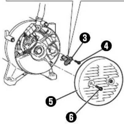
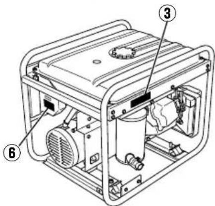
Please fill in the following blanks after checking the production number on your product. (Location of label is different depending on the product model.)

CONTENTS
Page
-
SAFETY PRECAUTIONS .....2
-
COMPONENTS....5
-
PRE-OPERATION CHECKS.....5
-
OPERATING PROCEDURES ......7
-
WATTAGE INFORMATION....11
-
SPARK ARRESTER ..... 12
-
MAINTENANCE SCHEDULE 13
-
"HOW-TO" MAINTENANCE ....14
-
PERIODIC OPERATION AND INSPECTION .....15
-
TRANSPORTING 15
-
PREPARATION FOR STORAGE 16
-
TROUBLESHOOTING ..... 16
-
SPECIFICATIONS....17
-
WIRING DIAGRAM 18
-
OPTIONAL PARTS .....20
NOTE Please refer to the illustrations on the back page of the front cover or back cover for Fig.1 to 6 indicated in the sentence.
1. SAFETY PRECAUTIONS
Please make sure you review each precaution carefully.
Pay special attention to statement preceded by the following words.
WARNING
"WARNING" indicates a strong possibility of severe personal injury or loss of life if instructions are not followed.
CAUTION
"CAUTION" indicates a possibility of personal injury or equipment damage if instructions are not followed.
WARNING
Do not operate the generator near gasoline or gaseous fuel because of the potential danger of explosion or fire.
Do not fill the fuel tank with fuel while the engine is running. Do not smoke or use open fl ame near the fuel tank. Be careful not to spill fuel during refueling.
If fuel is spilt, wipe it off and let dry before starting the engine.


WARNING
Do not place in fl ammables near the generator.
Be careful not to place fuel, matches, gunpowder, oily cloths, straw, trash, or any other in flammables near the generator.
WARNING
Do not operate the generator inside a room, cave, tunnel, or other insufficiently ventilated area.
Always operate it in a well-ventilated area, otherwise the engine may become overheated, and the poisonous carbon monoxide gas, an odorless, colorless, poison gas, contained in the exhaust gas will endanger human lives.
Operate generator only outdoors and far from open windows, doors, ventilation intakes and other openings.
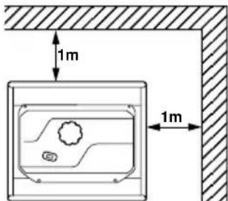
Keep the generator at least 1 meter (3 feet) away, including overhead, from any structure or building use.

WARNING
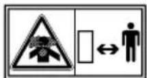
Do not enclose the generator nor cover it with a box.
The generator has a built-in forced air cooling system, and may become overheated if it is enclosed.
If generator has been covered to protect it from the weather during non use, be sure to remove it and keep it well away from the area during generator use.
WARNING
Operate the generator on a level surface.
It is not necessary to prepare a special foundation for the generator.
However, the generator will vibrate on an irregular surface, so choose a level place without surface irregularities.
If the generator is tilted or moved during operation, fuel may spill and / or the generator may tip over, causing a hazardous situation.
Proper lubrication cannot be expected if the generator is operated on a steep incline or slope. In such a case, piston seizure may occur even if the oil is above the upper level.
WARNING
Pay attention to the wiring or extension cords from the generator to the connected device.
If the wire is under the generator or in contact with a vibrating part, it may break and possibly cause a fi re, generator burnout, or electric shock hazard.
Replace damaged or worn cords immediately.
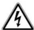
WARNING
Do not operate in rain, in wet or damp conditions, or with wet hands.
The operator may suffer severe electric shock if the generator is wet due to rain or snow.
WARNING
If wet, wipe and dry it well before starting. Do not pour water directly over the generator, nor wash it with water.
WARNING
Be extremely careful that all necessary electrical grounding procedures are followed during each and every use. Failure to do so can be fatal.
WARNING
Do not contact the generator to a commercial power line. Connection to a commercial power line may short circuit the generator and ruin it or cause electric shock hazard.
Use the transfer switch for connecting to domestic circuit.

WARNING
No smoking while handling the battery. The battery emits flammable hydrogen gas, which can explode if exposed to electric arcing or open flame.
Keep the area well-ventilated and keep open flames/sparks away when handling the battery.

WARNING
Engine becomes extremely hot during and for some time after operation.
Keep combustible materials well away from generator area.
Be very careful not to touch any parts of the hot engine especially the muffler area or serious burns may result.

WARNING
Keep children and all bystanders at a safe distance from work areas.
WARNING
It is absolutely essential that you know the safe and proper use of the power tool or appliance that you intend to use. All operators must read, understand and follow the tool/appliance owners manual. Tool and appliance applications and limitations must be understood. Follow all directions given on labels and warnings. Keep all instruction manuals and literature in a safe place for future reference.
WARNING
Use only "LISTED" extension cords.
When a tool or appliance is used outdoors, use only extension cords marked "For Outdoor Use". Extension cords, when not in use should be stored in a dry and well ventilated area.
WARNING
Always switch off generator's AC circuit breaker and disconnect tools or appliances when not in use, before servicing, adjusting, or installing accessories and attachments.
CAUTION
Make sure the engine is stopped before starting any maintenance, servicing or repair.
Make sure maintenance and repair of the generator set are performed by properly trained personnel only.
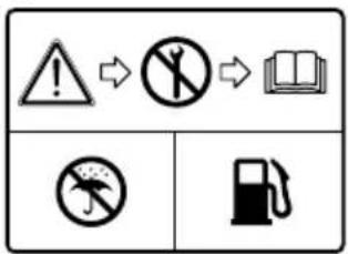
Symbols and Meanings
In accordance with the European requirements (eec Directives), the specified symbols as shown in the following table are used for the products and this instruction manual.
 | Read the operator's instruction manual. |  | Fire, open light and smoking prohibited. |
 | Stay clear of the hot surface. |  | Do not connect the generator to the commercial power lines. |
 | Exhaust gas is poisonous.Do not operate in an unventilated room. |  | Do not operate in rain or snow. |
 | Stop the engine before refueling. |  | Call for maintenance. |
 | Caution, risk of electric shock. |  | Keep dry. |
 | HOT, avoid touching the hot area. |
| ON(power and Engine) | IN-position of a bistable push control | Engine start (Electric start) | |||
| OFF(power and Engine) | Protective earth (ground) | Engine stop | |||
| Alternating current | Fuse | Gasoline | |||
| Direct current | Engine oil | Fast | |||
| Plus; positive polarity | Add oil | Slow | |||
| Minus; negative polarity | Battery charging condition | Fuel start / Open | |||
| OUT-position of a bistable push control | Choke; cold starting aid | Fuel stop / Close |
| Pr | Rated power (kW) | COP | Continuous power | COSr | Rated power factor |
| fr | Rated frequency (Hz) | Ur | Rated voltage (V) | Ir | Rated current (A) |
| Hmax | Maximum site altitude above sea-level (m) | Tmax | Maximum ambient temperature (°C) | m | Mass (kg) |
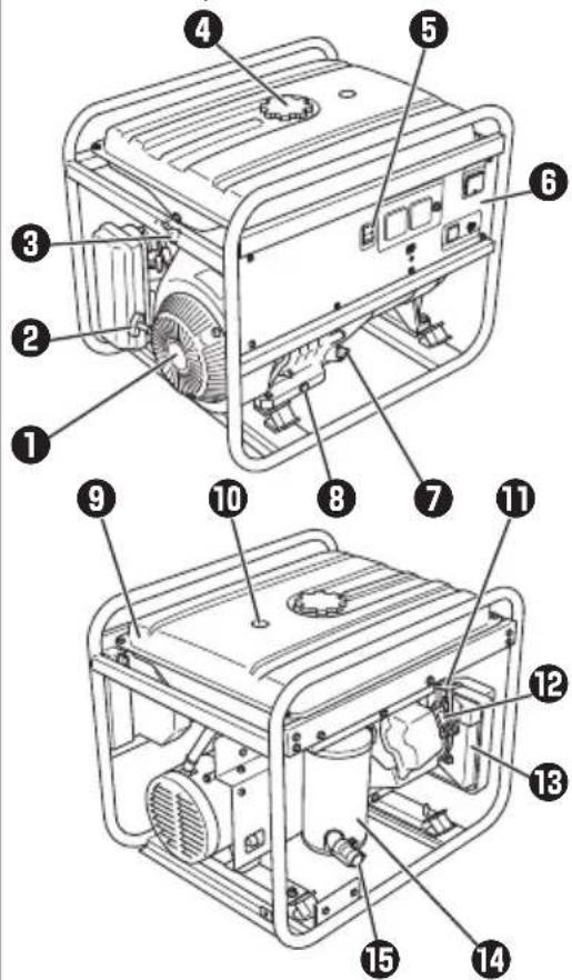
2. COMPONENTS 3. PRE-OPERATION CHECKS
(See Fig. 1) (See Fig. 2)
NOTE
Please refer to the illustrations on the back page of the front cover or back cover for Fig.1 to 6 indicated in the sentence.
EG241A, EG321A, EG321AE, EG441A, EG441AE (See Fig. 1-①)
① RECOIL STARTER
② RECOIL STARTER HANDLE
③ FUEL STRAINER (FUEL VALVE)
④ FUEL TANK
⑤ ENGINE SWITCH
⑥ CONTROL PANEL
⑦ OIL GAUGE (OIL FILLER)
⑧ OIL DRAIN PLUG
⑨ FUEL GAUGE
⑩ TANK CAP
⑪ SPARK PLUG CAP
⑫ CHOKE LEVER
13 AIR CLEANER
14 EXHAUST OUTLET
15 MUFFLER COVER
EG601A, EG601AE, EG671A, EG671AE (See Fig. 1-2)
① RECOIL STARTER
② RECOIL STARTER HANDLE
③ FUEL STRAINER (FUEL VALVE)
④ TANK CAP
⑤ ENGINE SWITCH
6 CONTROL PANEL
⑦ OIL GAUGE (OIL FILLER)
⑧ OIL DRAIN PLUG
⑨ FUEL TANK
⑩ FUEL GAUGE
⑪ CHOKE LEVER
⑫ SPARK PLUG CAP
13 AIR CLEANER
14 MUFFLER
⑮ EXHAUST OUTLET
1. CHECK ENGINE OIL (See Fig. 2-①,②)
Before checking or refi lling oil, be sure generator is located on stable and level surface with engine stopped.
Remove oil filler cap and check the engine oil level. (See Fig.2-①)
① OIL GAUGE
② OIL FILLER
③ UPPER LEVEL
④ LOWER LEVEL
Oil level is below the lower level line, refi ll with suitable oil (see table) to upper level line. Do not screw in the oil fi ller cap when checking oil level. (See Fig. 2-②)
① UPPER LEVEL
② LOWER LEVEL
Change oil if contaminated.
(See "How-To" Maintenance.)
Oil capacity (Upper level) : (L)
| EG241A | 0.6 |
| EG321A, EG321AE | 0.6 |
| EG441A, EG441AE | 1.0 |
| EG601A, EG601AE | 1.2 |
| EG671A, EG671AE | 1.2 |
Recommended engine oil:
Use 4-stroke automotive detergent oil of API service class SE or highergrade (SG, SH or SJ is recommended).
SAE 10W-30 or 10W-40 is recommended for general, all-temperature use.
If single viscosity oil is used, select the appropriate viscosity for the average temperature in your area.

bar
| Category | Temperature Range (°C) | |---|---| | Single grade | -20 to 5W | | Single grade | -4 to 10W | | Single grade | 10W to 20W | | Single grade | 20W to #20 | | Single grade | 20W to #30 | | Single grade | 20W to #40 | | Multigrade | -20 to 10W-30 | | Multigrade | -4 to 10W-40 | | Multigrade | 10W-30 to 10W-40 | | Ambient temperature | -20 to 10W-30 | | Ambient temperature | -4 to 10W-40 | | Ambient temperature | 10W-30 to 10W-40 | | Ambient temperature | 10W-40 to 40°C | | Ambient temperature | 40°C to 104°F |2. CHECK ENGINE FUEL (See Fig. 2-③,④)
WARNING
Do not refuel while smoking or near open f1 ame or other such potential f1 re hazards. Otherwise f1 re accident may occur.
Check fuel level at fuel level gauge (See Fig.2-③)
■ fuel level is low, refi II with unleaded automotive gasoline.
Be sure to use the fuel filter screen on the fuel filter neck. (See Fig.2-4)
① LEVEL
② FUEL TANK CAP
③ FUEL FILTER SCREEN
Fuel Amount up to "LEVEL" position : (L)
| EG241A | 12.8 |
| EG321A, EG321AE | 12.8 |
| EG441A, EG441AE | 12.8 |
| EG601A, EG601AE | 22.0 |
| EG671A, EG671AE | 22.0 |
WARNING
Make sure you review each warning in order to prevent fire hazard.
Do not refi ll tank while engine is running or hot.
- lose fuel cock before refueling with fuel.
Be careful not to admit dust, dirt, water or other foreign objects Into fuel.
Wipe off spilt fuel thoroughly before starting engine.
Keep open fl ames away.
3. CHECKING COMPONENT PARTS
Check following items before starting engine:
Fuel leakage from fuel hose, etc.
Bolts and nuts for looseness.
Components for damage or breakage.
Generator not resting on or against any adjacent wiring.
4. CHECK GENERATOR SURROUNDINGS
WARNING
Make sure you review each warning in order to prevent fire hazard.
Keep area clear of in £1 ammables or other hazardous materials.
- Keep generator at least 3 feet (1 meter) away from buildings or other structures.
■Only operate generator in a dry, well ventilated area. - Keep exhaust pipe clear of foreign objects.
- Keep generator away from open flame. No smoking!
- Keep generator on a stable and level surface.
■Do not block generator air vents with paper or other material.
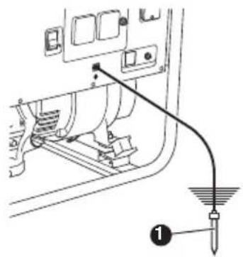
5. GROUNDING THE GENERATOR
To ground the generator to the earth, connect the grounding lug of the generator to the grounding spike driven into the earth or to the conductor which has been already grounded to the earth. (See Fig.2-⑤)
① GROUNDING SPIKE
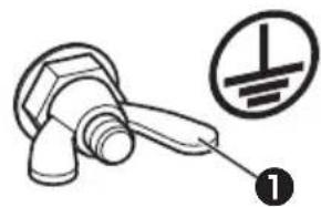
such grounding conductor or grounding electrode is unavailable, connect the grounding lug of the generator to the grounding terminal of the using electric tool or appliance. (See Fig.[2]-⑥)
① GROUND TERMINAL
6. BATTERY INSTALLATION (See Fig. 2-7) (Electric Starter Model)
Recommended Battery
Type ; Lead-acid battery
Capacity
(Ah/5hr) ; 12V-21AH or more
Size ; Less than 185(L) x 125(W) x 160(H) mm
① EARTH CABLE(BLACK)
② STARTER CABLE(RED)
③ SETTING PLATE
④ SETTING BOLT
⑤ BATTERY PLATE
⑥ BATTERY FRAME #1
⑦ BATTERY FRAME #2
8 PROTECTION PLATE
⑨ BOLT
10 NUT
WARNING
Death, personal injury and/or property damage may occur unless instructions are followed carefully.
Use battery of recommended capacity.
Turn the starter switch to the “O” (STOP) position when mounting or dismounting battery. When mounting battery, connect the positive (+) cable fi rst and then the negative (-) cable to the battery. Be careful not to short battery cables. When dismounting battery, disconnect negative (-) cable fi rst.
RED CABLE : To positive (+) terminal BLACK CABLE : To negative (-) terminal
Should the connection be made in incorrect manner, the generator will be broken.
Tighten bolts and nuts on terminals securely so they will not be loosened by vibration.
Disconnect battery cables when charging battery.
4. OPERATING PROCEDURES
(See Fig. 3)
1. STARTING THE GENERATOR
CAUTION
Check the oil level before each operations as outlined by the article "CHECK ENGINE OIL"
(a) Turn the Engine switch to the position “I” (ON). (See Fig.3-①)
① “ | ” (ON)
② “O” (OFF)
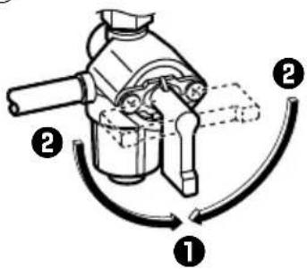
(b) Open the fuel valve. (See Fig.3-②)
① OPEN
② CLOSE
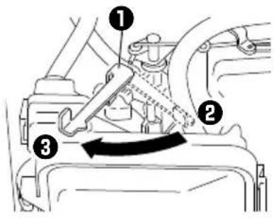
(c) Set choke lever to close if the engine is cold. (See Fig.3-③)
① CHOKE LEVER
② CLOSE
③ OPEN
Pull the starter handle slowly until passing the compression point (resistance will be felt), then return the handle to its original position and pull briskly. (See Fig.3-4)
① PULL BRISKLY
If the engine fails to start after several attempts, repeat above procedures with choke lever returned to "OPEN" position.
Do not fully pull out the rope.
After starting, allow the starter handle to return to its original position while still holding the handle.
(e) [Electric starter model]
Insert the key into the key switch and turn it clockwise to the “|” (RUN) position to start the engine.
Then turn the key further to the “ Ⓞ” (START) position.
The engine will be started by starting motor. (See Fig.3-5)
① “O” (STOP)
② “ | ” (RUN)
③ “ 🔍 ” (START)
CAUTION
Do not run the starting motor over 5 seconds continuously.
If the engine fails to start, return the key to the “|” (RUN) position and wait about 10 seconds then start again.
Do not turn the key switch to “ ⏻ ” (START) position when the engine is running to prevent damage of starting motor.
When starting the engine by recoil starter, set the key switch at the “|” (RUN) position and pull the starter handle.
(f) After the engine started, return the choke lever gradually to "OPEN" position.
(See Fig.3-6)
① CHOKE LEVER
② CLOSE
③ OPEN
(g) Warm up the engine without a load for a few minutes.
2. USING ELECTRIC POWER
WARNING
Make sure that the appliance is switched OFF before connecting it to the generator.
Do not move the generator while it is running.
Be sure to ground the generator if the connected appliance is grounded. Failure to ground unit may lead to electrical shock.
CONTROL PANEL
EN
(EG241A, EG321A, EG321AE)
![[Electric starter model] Key switch Engine switch AC receptacle 20A AC circuit breaker Volt meter DC circuit breaker Earth (ground) terminal DC receptacle](/content/2026/05/1121455/images/45a4d03ac4f6da0cd9ba15037ddfa5bac830df9810cbfdd5ac91ed35d2926790.jpg)
(EG441A, EG441AE, EG601A, EG601AE, EG671A, EG671AE)
![[Electric starter model] Key switch Engine switch AC receptacle 20A AC circuit breaker Volt meter DC circuit breaker Earth (ground) terminal DC receptacle](/content/2026/05/1121455/images/a0db439c9084f3ddf16b3a52195d5e33f583bf431cbe83c7f8d9661901768b78.jpg)
(1) AC APPLICATION
(a) Check the voltmeter for proper voltage. (See Fig.4-①)
This generator is thoroughly tested and adjusted in the factory.
If the generator does not produce the specified voltage, consult your nearest Makita factory or authorized service center.
(b) Turn off the switch (es) of the electrical appliance (s) before connecting to the generator.
(c) Insert the plug (s) of the electrical appliance(s) into the receptacle.

natural_image
Technical line drawing of a mechanical assembly with a cable and housing, showing no text or symbols.Check the amperage of the receptacles, and be sure not to take a current exceeding the specified amperage.
Be sure that the total wattage of all appliances dose not exceed the rated output of the generator.
CAUTION
Do not put foreign objects into the plug receptacle.
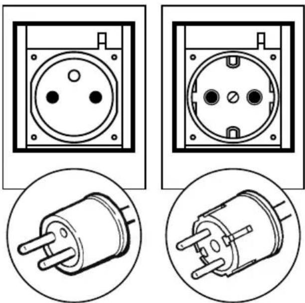
natural_image
Four technical line drawings of electrical socket components, shown from different angles (front, side, top, and bottom) with no visible text or symbols.WARNING
Be sure to ground the generator if the connected electrical device is grounded.
NOTE
When the AC circuit breaker turns off during operation, the generator is over loaded or the appliance is defective.
Stop the generator immediately, check the appliance and / or generator for overloading or detect and have repaired as necessary by Makita factory or authorized service center.
(d) Check and confirm whether circuit breaker position is "I" (ON). (See Fig.4-②)
① “|” (ON)
(e) Turn on the switch of the appliance.
(2) DC APPLICATION
(Only for charging 12 volt battery)
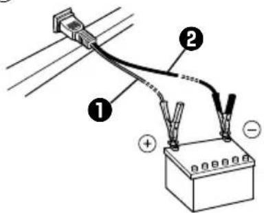
DC receptacle (Only for charging 12 volt battery) (See Fig.4-③)
① RED CABLE
② BLACK CABLE
For charging 12 voltage battery, 12V-8.3A (100W) of maximum AC power can be taken out from the DC receptacle by means of the exclusive DC cable. (See Fig.4-④)
The exclusive DC cable is come with your generator set (included in the package) (See Fig.4-⑤).
DC Circuit Breaker
DC circuit breaker is turned off to shut down the DC power, when the DC is over the usage range or the battery is defective.
Check the generator and/or battery for overloading or defect, and turn on the DC circuit breaker after no problem and defect are found out.
Connection of exclusive DC cable :
Connect positive (red) clip of DC cable to positive (+) terminal on battery.
Connect negative (black) clip of DC cable to negative (-) terminal on battery.
Battery Charging Procedures :
1) Stop engine.
2) Remove all connections from battery.
3) Insert the plug of exclusive DC cable into DC receptacle.
4) Connect positive (red) clip of DC cable to positive (+) terminal on battery, and then connect negative (black) clip of DC cable to negative (-) terminal on battery.
5) Take out all plugs at the battery electrolyte fluid filler ports.
6) Check the electrolyte fluid level, and refill the distilled water as necessary.
7) Start engine.
8) Make sure that the pilot lamp is turned on.
9) Make sure that the DC circuit breaker is in the ON position.
10) Battery charging will be started.
CAUTION
Do not use both AC and DC output at the same time.
Install correct positive (red) or negative (black) cable to the correct polarity on the battery.
Connect and disconnect DC cable with engine stopped.
An explosive hydrogen gas is discharged through vent holes in the battery during the charging process.
Do not allow spark or open flame around the generator or battery during the charging process.
Electrolyte π uid contains sulphuric acid, and so the π uid can burn eyes and clothing. Be extremely careful to avoid contact.
If injured, wash the affected area immediately with large quantities of water and consult a doctor for treatment.
●Charging time is varied according to the kind of battery and discharged level of battery.
Measure the specific gravity of electrolyte fluid by means of hydrometer every one hour during battery charging.
Make sure if the DC circuit breaker is not turned off.
Battery charging is completed when the specific gravity is in the range of 1.26 to 1.28.
3. STOPPING THE GENERATOR
(a) Turn off the power switch of the electric equipment and unplug the cord from receptacle of the generator.
(b) Allow the engine about 3 minutes to cool down at no-load before stopping.
(c) [Recoil starter model]
Turn the engine switch to the position “O” (OFF). (See Fig.4-6)
① “ | ” (ON)
② “O” (OFF)
[Electric starter model]
Turn the key switch to the STOP position.
(See Fig.4-⑦)
① “O” (STOP)
② “ | ” (RUN)
③ “ ” (START)
(a) The oil sensor detects the fall in oil level in the crankcase and automati-cally stops the engine when the oil level falls below a predetermined level.
(b) When engine has stopped automatically, switch off generator's AC circuit breaker, and check the oil level.
Refi II engine oil to the upper level as instructed on page 5 and restart the engine.
(c) If the engine does not start by usual starting procedures, check the oil level.
5. WATTAGE INFORMATION
Some appliances need a "surge" of energy when starting.
This means that the amount of electrical power needed to start the appliance may exceed the amount needed to maintain its use.
Electrical appliances and tools normally come with a label indicating voltage, cycles / Hz, amperage (amps) and electrical power needed to run the appliance or tool.
Check with your nearest dealer or service center with questions regarding power surge of certain appliances or power tools.
Electrical loads such as incandescent lamps and hot plates require the same wattage to start as is needed to maintain use.
■loads such as fluorescent lamps require 1.2 to 2 times the indicated wattage during start-up.
■loads for mercury lamps require 2 to 3 times the indicated wattage during start-up.
Electrical motors require a large starting current. Power requirements depend on the type of motor and its use. Once enough "surge" is attained to start the motor, the appliance will require only 50% to 30% of the wattage to continue running.
Most electrical tools require 1.2 to 3 times their wattage for running under load during use. For example, a 5,000 watt generator can power a 1800 to 4000 watt electrical tool.
■loads such as submersible pumps and air compressors require a very large force to start. They need 3 to 5 times the normal running wattage in order to start.
For example, a 5,000 watt generator would only be able to drive a 1,000 to 1,700 watt pump.
NOTE
The following wattage chart is general guide only. Refer to your specific appliance for correct wattage.
To determine the total wattage required to run a particular electrical appliance or tool, multiply the voltage figure of the appliance/tool by the amperage (amps) figure of same. The voltage and amperage (amps) information can be found on a name plate which is normally attached to electrical appliances and tools.
| Applications | Applicable Wattage(W) | ||||
| EG241A | EG321A EG321AE | EG441A EG441AE | EG601A EG601AE | EG671A EG671AE | |
| Incandescent lamp, Heater 2000 2400 | 3600 4600 5 | 500 | |||
| Fluorescent lamp, Electric tool 1100 | 1300 2000 25 | 50 3050 | |||
| Mercury lamp 800 950 1450 1850 2 | 200 | ||||
| Pump, Compressor 500 600 900 | 150 1400 | ||||
VOLTAGE DROP IN ELECTRIC EXTENSION CORDS
When a long electric extension cord is used to connect an appliance or tool to the generator, a certain amount of voltage drop or loss occurs in the extension cord which reduces the effective voltage available for the appliance or tool. The chart below has been prepared to illustrate the approximate voltage loss when an extension cord of 300 feet (approx. 100 meters) is used to connect an appliance or tool to the generator.
| Nominal cross section | A.W.G. | Allowable current | No.of strands / strands dia. | Resistance | Current Amp. | |||||||
| mm2 | No. A No./mm | Ω/100m 1 | A 3A 5 | A 8A 1 | 10A 12 | A 15A | Voltage drop | |||||
| 0.75 | 18 | 7 | 30/0.18 | 2.477 | 2.5V | 8V | 12.5V | — | — | — | — | |
| 1.27 | 16 | 12 | 50/0.16 | 1.486 | 1.5V | 5V | 7.5V | 12V | 15V | 18V | — | |
| 2.0 | 14 | 17 | 37/0.26 | 0.952 | 1V | 3V | 5V | 8V | 10V | 12V | 15V | |
| 3.5 | 12 to 10 | 23 | 45/0.32 | 0.517 | — | 1.5V | 2.5V | 4V | 5V | 6.5V | 7.5V | |
| 5.5 | 10 to 8 | 35 | 70/0.32 | 0.332 | — | 1V 2V | 2.5V | 3.5V | 4V | 5V | ||
6. SPARK ARRESTER
In a dry or wooded area, it is recommendable to use the product with a spark arrester. Some areas require the use of a spark arrester. Please check your local laws and regulations before operating your product.
The spark arrester must be cleaned regularly to keep it functioning as designed.
A clogged spark arrester :
●Prevents the flow of exhaust gas
- Reduces engine output
- Increases fuel consumption
●Makes starting diffi cult
If the engine has been running, the muffler and the spark arrester will be very hot. Allow the muffler to cool before cleaning the spark arrester.
EN
How to remove the spark arrester
- Remove the flange bolts from the muffler cover and remove the muffler cover.
- Remove the special screw from the spark arrester and remove the spark arrester from the muffler.

Clean the spark arrester screen
Use a brush to remove carbon deposits from the spark arrester screen.
Be careful to avoid damaging the screen.
The spark arrester must be free of breaks and holes. Replace the spark arrester if it is damaged.
Install the spark arrester, and muffler protector in the reverse order of disassembly.

| DAILY | Check oil level.Check all components according to “PRE-OPERATION CHECKS.” |
| EVERY50 HOURS | Wash cleaner element. -more often if used in dirty or dusty environments.Check spark plug, clean if necessary. |
| EVERY100 HOURS | Change engine oil. *-more often if used in dusty or dirty environments.Clean spark arrester. |
| EVERY200 HOURS | Adjust spark plug gap.Clean fuel strainer. |
| EVERY500 HOURS | Replace spark plug and cleaner element.Clean and adjust carburetor, valve clearance, and valve seat along with cylinder head.Check and replace carbon brushes |
| EVERY1,000 HOURS(24 MONTHS) | Inspect control panel parts.Check rotor and starter.Replace engine mount rubber.Overhaul engine.Change fuel lines. |
NOTE : (\*)
Initial oil change should be performed after first twenty (20) hours of use. Thereafter change oil every 100 hours.
Before changing the oil, check for a suitable way to dispose of the old oil.
Do not pour it down sewage drains, onto garden soil or into open streams.
Your local zoning or environmental regulations will give you more detailed instructions on proper disposal.
8. "HOW-TO" MAINTENANCE
CAUTION
Make sure the engine is stopped before starting any maintenance, servicing or repair.
NOTE
It is recommended to use ear protection when performing operation, maintenance and repair of the generator set.
ENGINE OIL CHANGE (See Fig. 5-①)
Change engine oil every 100 hours. (For new engine, change oil after 20 hours.)
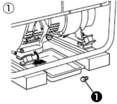
(a) Drain oil by removing the drain plug and the oil filler cap while the engine is warm.
① OIL DRAIN PLUG
(b) Reinstall the drain plug and fi ll the engine with oil until it reaches the upper level on the oil fi ller cap.
Use fresh and high quality lubricating oil to the specified level as directed on page 5. If contaminated or deteriorated oil is used or the quantity of the engine oil is not sufficient, the engine damage will result and its life will be greatly shortened.
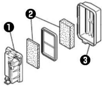
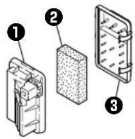
SERVICING THE AIR CLEANER
(See Fig. 5-② thru ④)
Maintaining an air cleaner in proper condition is very important.
Dirt induced through improperly installed, improperly serviced or inadequate elements damages and wears out engines. Keep the element always clean.
① BASE
② ELEMENT
③ AIR CLEANER COVER
④ BOLT
(a) Remove the bolt of air cleaner cover.
(EG601A, EG601AE, EG671A, EG671AE)
(See Fig.5-④)
Remove the air cleaner cover and cleaner element.
(b) Urethane form : Wash urethane form element in kerosene or diesel fuel.
Then saturate the element in a mixture of 3 parts kerosene or diesel fuel and 1 part engine oil.
Squeeze the element to remove the mixture and install it in the air cleaner.
NOTE
Instead of washing oil (kerosene), it is possible to wash the urethane foam element in a solution of mild detergent and warm water.
Then rinse the element thoroughly in clean water. Allow the element to dry thoroughly. Soak the element in clean engine oil and squeeze out excess oil.
CLEANING AND ADJUSTING SPARK PLUG (See Fig. 5-⑤)
(a) If the plug is contaminated with carbon, remove it using a plug cleaner or wire brush.
(b) Adjust the electrode gap to 0.6 to 0.7 mm.
Spark plug : BR-6HS (NGK)
CLEANING FUEL STRAINER
(See Fig. 5-6)
Dirt and water in the fuel are removed by the fuel strainer.
(a) Remove the strainer cup and throw away water and dirt.
(b) Clean the screen and strainer cup with gasoline.
(c) Tightly fasten the cup to main body, making sure to avoid fuel leak.
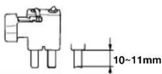
CHECKING CARBON BRUSH
Brush Maintenance Essentials (Effective Length)
The brush is the area which touches the slip ring, and its surface must be kept smooth.
If it is not smooth then carbon and other substances will adhere between the brush and slip ring.
This must be buffed with sandpaper or the like because it is hazardous.
The usable length of the brush is 5\~11mm, so if the brush is 5mm long or less replace it with a new one. (See Fig.5-⑦)
① LENGTH WHEN NEW
② EFFECTIVE BRUSH LENGTH
This is done because if the length of the brush gets any shorter, its contact pressure with the slip ring will decrease, resulting in a drop in generator efficiency and the output voltage.
Check the brush every 500 hours to confirm its length. In addition, check the brush length if the generator malfunctions, such as when it is not generating power or its voltage is low.
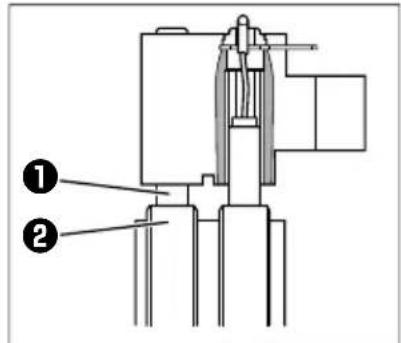
Brush Maintenance Essentials
(Disassembly and Assembly) (See Fig. 5-8)
① BRUSH
② SLIP RING
③ BRUSH HOLDER
④ FLANGE BOLTS
⑤ BRACKET COVER
⑥ FLANGE BOLTS
Disassembly
- Remove the two fl ange bolts (M5 x 20), then remove the bracket cover.
- Remove the two fl ange bolts (M5 x 16), then remove the brush.
Assembly
- While pressing the brush against the slip ring, secure it (1.5\~2N•m) by tightening it with the two fl ange bolts (M5 × 16).
When doing so, confirm that the brush is in the proper position relative to the slip ring. - Secure the bracket cover (3\~4N·m) by tightening it with the two flange bolts (M5 × 20).
9. PERIODIC OPERATION AND INSPECTION
When furnishing the generator as emergency electric power source, periodic operation and inspection are needed.
Fuel (gasoline) and engine oil will be deteriorated with time, and this causes that the engine is difficult to start and as the results improper engine operation and fault.
CAUTION
Since the fuel (gasoline) will be deteriorated with time, replace fuel (gasoline) with fresh one periodically; once every three (3) months is recommended.
(a) Check the fuel (gasoline), engine oil and air cleaner.
(b) Start engine.
(c) With appliance such as lightings activated, run the engine for over ten minutes.
(d) Check for the following items;
■Proper engine running.
Adequate output and the indicator lamp turned on properly.
The engine switch normally operated.
No leakage of engine oil and fuel (gasoline).
10. TRANSPORTING
When transporting the generator, make sure that the fuel (gasoline) should be drained from the tank.
WARNING
To prevent fuel spillage due to the vibration and impact, never transport the generator with the fuel (gasoline) filled in the tank.
Secure the tank cap thoroughly.
To avoid the risk of the gasoline Ω immability, never leave the generator in an area exposed to direct sunlight or high temperatures for a long time.
Keep the fuel (gasoline) in the exclusive gasoline storage tank made by steel when transporting.
(a) Turn the engine switch to the "STOP" position.
(b) Drain the fuel from the tank.
(c) Secure the tank cap.
CAUTION
Do not place any heavy objects on the generator.
Select and place the generator in the proper position of the transport vehicle so that the generator not be moved or fallen down.
Fix the generator with rope as necessary.
11. PREPARATION FOR STORAGE
(See Fig. 6)
The following procedures should be followed prior to storage of your generator for periods of 6 months or longer.
Drain fuel from fuel tank carefully by disconnecting the fuel line.
Gasoline left in the fuel tank will eventually deteriorate making engine-starting difficult.
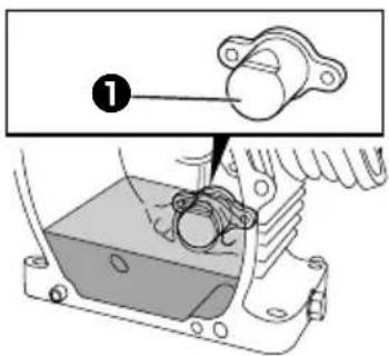
Remove the carburetor float chamber and also drain the carburetor. (See Fig.6-①)
① DRAIN SCREW
Change engine oil.
☑ check for loose bolts and screws, tighten them if necessary.
- clean generator thoroughly with oiled cloth.
Spray with preservative if available.
NEVER USE WATER TO CLEAN GENERATOR!
■ull starter handle until resistance is felt, leaving handle in that position.
Store generator in a well ventilated, low humidity area.
12. TROUBLESHOOTING
When generator engine fails to start after several attempts, or if no electricity is available at the output socket, check the following chart. If your generator still fails to start or generate electricity, contact your nearest Makita factory or authorized service center for further information or corrective procedures.
When Engine Fails to Start:
| Check if choke lever is in its proper position. Set the choke lever to “CLOSE” position. | |
| Check if fuel valve is open. | If closed, open fuel valve. |
| Check fuel level. | If empty, refill fuel tank making sure not to overfill. |
| Check if engine switch is in OFF. Turn engine switch to ON. | |
| Check to make sure generator is not connected to an appliance. | If connected, turn off the power switch on the connected appliance and unplug. |
| Check spark plug for loose spark plug cap. | If loose, push spark plug cap back into place. |
| Check spark plug for contamination. Remove spark plug and clean electrode. | |
When No Electricity Is Generated at Receptacle:
| Check to make sure AC circuit breaker is in the “ON” position. | ↔ | After making sure that the total wattage of the electrical appliance is within permissible limits and there are no defects in the appliance, turn the AC circuit breaker to the “ON” position. If breakers continue to actuate, consult your nearest servicing dealer. |
| Check AC receptacle and DC terminals for loose connection. | Secure connection if necessary. | |
| Check to see if engine starting was attempted with appliances already connected to generator. | Turn off switch on the appliance, and disconnect cable from receptacle. Reconnect after generator has been started properly. | |
| Low power. Carbon brushes are excessively worn |
13. SPECIFICATIONS
| MODEL EG241A | EG321AEG321AE | EG441AEG441AE | EG601AEG601AE | EG671AEG671AE | ||
| Generator | Type Brush, self-exciting, 2-poles, single phase | |||||
| Voltage regulating system AVR type | ||||||
| AC OutputRated voltage-Frequency V-Hz 230 - 50 | ||||||
| Rated current A 8.7 10.4 15.7 20.0 23.9 | ||||||
| Rated output VA (W) 2000 2400 3600 4600 5500 | ||||||
| Maximum output VA (W) 2400 3200 4400 6000 6700 | ||||||
| Rated power factor 1.0 | ||||||
| Safety device type Fuse-less circuit breaker | ||||||
| DC OutputRated voltage V 12 | ||||||
| Rated current A 8.3 | ||||||
| Safety device type Fuse-less circuit breaker | ||||||
| Engine | Model | EX17D | EX21D | EX30D | EX35D | EX40D |
| Type | ROBIN, Air-cooled, 4-stroke, OHC, Gasoline Engine | |||||
| Displacement mL | 169 211 | 287 | 404 | |||
| Fuel | Automotive Unleaded Gasoline | |||||
| Fuel tank capacity L | 12.8 | 22.0 | ||||
| Engine oil capacity L | 0.6 | 1.0 | 1.2 | |||
| Rated continuous operation H | 10.5 | 9.0 | 5.6 | 7.5 | 6.6 | |
| Spark plug | BR-6HS (NGK) | |||||
| Starting system | Recoil starter | Electric starter / Recoil | ||||
| 3/4Load Fuel consumption L/H | 1.0 | 1.3 | 1.9 | 2.7 | 2.9 | |
| Direction of rotation | Counter-clockwise | |||||
| Dimension | Length mm | 600 | 620(870)*1 | 675(925)*1 | 725(975)*1 | |
| Width mm | 420 450 | 510 | 530 | |||
| Height mm | 500 500 | 540 | 580 | |||
| Dry weight kg | 47 | 51(56)*2 | 67(77)*2 | 86(96)*2 | 88(98)*2 | |
| Gross weight Weight according to EPTA procedure 01/2003 kg | 57 | 61(66)*2 | 78(88)*2 | 104(114)*2 | 106(116)*2 | |
Specifications are subject to change without notice.
*1: ( ) shows dimensions with Battery frame.
*2: ( ) shows weight with Electric starter.
EG241A, EG321A (50Hz-230V) [Recoil starter model]

flowchart
graph TD
    subgraph GENERATOR
        A["Generator"] --> B["Blk"]
        B --> C["Ignition coil"]
        C --> D["Oil sensor switch"]
        D --> E["Org"]
        E --> F["Blk"]
        F --> G["Y/R"]
        G --> H["Oil sensor unit"]
        H --> I["Engine switch"]
        J["Control Box Engine"] --> K["Blk"]
        K --> L["Grn"]
    end

    subgraph CONTROL Box Engine
        M["Blk"] --> N["Engine switch"]
    end

    subgraph OUTPUT System
        O["AC output receptacle"] --> P["Voltmeter"]
        P --> Q["GryOrg"]
        Q --> R["Gry"]
        R --> S["Gry"]
        S --> T["Noise filter"]
        T --> U["R"]
        U --> V["R"]
        V --> W["AC circuit breaker"]
        W --> X["AC circuit breaker"]
        X --> Y["AC output"]
        Y --> Z["AC output receptacle"]
        AA["DC circuit breaker"] --> AB["W"]
        AB --> AC["DC12V"]
        AD["DC Output receptacle"] --> AE["DC12V"]
    end

    subgraph Earth
        AF["Earth (Ground) terminal"]
    end

    subgraph POWER
        AG["AVR unit"] --> AH["BRn"]
        AH --> AI["Blu"]
        AI --> AJ["Sub coil"]
        AJ --> AK["Blm"]
        AK --> AL["Stator"]
        AL --> AM["Rotator"]
        AM --> AN["Slip ring"]
        AN --> AO["Y/BLu"]
    end

    subgraph Power Supply
        AP["AC winding 1"] --> AQ["Gry"]
        AQ --> AR["GryOrg"]
        AR --> AS["Blu BLu"]
        AS --> AT["AC winding 2"]
        AT --> AU["Bry"]
        AU --> AV["BRn"]
        AV --> AW["BRn Bridge diode"]
        AW --> AX["BCD winding"]
    end

    style GENERATOR fill:#f9f,stroke:#333
    style CONTROL BoxEngine fill:#ccf,stroke:#333
    style Earth fill:#fff,stroke:#333
Wiring color code
Blk : Black
Blk/W : Black/White
Blu : Blue
LBlu : Light blue
Brn : Brown
Brn/W : Brown/White
Grn : Green
Grn/W: Green/White
Org : Orange
Gry : Gray
R : Red
W : White
Y : Yellow
W/Blk : White/Black
Grn/Y : Green/Yellow
Pur : Purple
EG321AE (50Hz-230V) [Electric starter model]

flowchart
graph TD
    subgraph Engine
        A["Blk"] --> B["Battery"]
        B --> C["Ignition coil"]
        C --> D["Oil sensor switch"]
        D --> E["Organ"]
        E --> F["Oil sensor unit"]
        F --> G["Magnetic switch"]
        G --> H["Electric Starter"]
        H --> I["Magnetic switch"]
        I --> J["Charge coil"]
        J --> K["Blu"]
        K --> L["Gry"]
        L --> M["Grn"]
        M --> N["Control Box"]
        N --> O["Org Fuse Org"]
        O --> P["Grn M- ST"]
        P --> Q["Gry IG M+ B"]
        Q --> R["Key switch"]
        R --> S["Grn"]
    end

    subgraph Generator
        T["Rotor"] --> U["Slip ring"]
        U --> V["Stator"]
        V --> W["AC winding 1"]
        V --> X["AC winding 2"]
        V --> Y["Sub coil"]
        V --> Z["Sub coil"]
        V --> AA["Sub coil"]
        V --> AB["Sub coil"]
        V --> AC["Sub coil"]
        V --> AD["Sub coil"]
        V --> AE["Sub coil"]
        V --> AF["Sub coil"]
        V --> AG["Sub coil"]
        V --> AH["Sub coil"]
        V --> AI["Sub coil"]
        V --> AJ["Sub coil"]
        V --> AK["Sub coil"]
        V --> AL["Sub coil"]
        V --> AM["Sub coil"]
        V --> AN["Sub coil"]
        V --> AO["Sub coil"]
        V --> AP["Sub coil"]
        V --> AQ["Sub coil"]
        V --> AR["Sub coil"]
        V --> AS["Sub coil"]
        V --> AT["Sub coil"]
        V --> AU["Sub coil"]
        V --> AV["Sub coil"]
        V --> AW["Sub coil"]
        V --> AX["Sub coil"]
        V --> AY["Sub coil"]
        V --> AZ["Sub coil"]
        V --> BA["Sub coil"]
        V --> BB["Sub coil"]
        V --> BC["Sub coil"]
        V --> BD["Sub coil"]
        V --> BE["Sub coil"]
        V --> BF["Sub coil"]
        V --> BG["Sub coil"]
        V --> BH["Sub coil"]
        V --> BI["Sub coil"]
        V --> BJ["Sub coil"]
        V --> BK["Sub coil"]
        V --> BL["Sub coil"]
        V --> BM["Sub coil"]
        V --> BN["Sub coil"]
        V --> BO["Sub coil"]
        V --> BP["Sub coil"]
        V --> BQ["Sub coil"]
        V --> BR["Sub coil"]
        V --> BS["Sub coil"]
        V --> BT["Sub coil"]
        V --> BU["Sub coil"]
        V --> BV["Sub coil"]
        V --> BW["Sub coil"]
        V --> BX["Sub coil"]
        V --> BY["Sub coil"]
        V --> BZ["Sub coil"]
        V --> CA["Sub coil"]
        V --> CB["Sub coil"]
        V --> CC["Sub coil"]
        V --> CD["Sub coil"]
        V --> CE["Sub coil"]
        V --> CF["Sub coil"]
        V --> CG["Sub coil"]
        V --> CH["Sub coil"]
        V --> CI["Sub coil"]
        V --> CJ["Sub coil"]
        V --> CK["Sub coil"]
        V --> CL["Sub coil"]
        V --> CM["Sub coil"]
        V --> CN["Sub coil"]
        V --> CO["Sub coil"]
        V --> CP["Sub coil"]
        V --> CQ["Sub coil"]
        V --> CR["Sub coil"]
        V --> CS["Sub coil"]
        V --> CT["Sub coil"]
        V --> CU["Sub coil"]
        V --> CV["Sub coil"]
        V --> CW["Sub coil"]
        V --> CX["Sub coil"]
        V --> CY["Sub coil"]
        V --> CZ["Sub coil"]
        V --> DA["Sub coil"]
        V --> DB["Sub coil"]
        V --> DC["Sub coil"]
        V --> DV["Sub coil"]
        V --> DW["Sub coil"]
        V --> DX["Sub coil"]
        V --> DXB["Sub coil"]
        V --> DXC[Circuit breaker W W DC Output receptacle DC12V DC Output receptacle DC12V DC Output receptacle DC12V DC Output receptacle DC12V DC Output receptacle DC12V DC Output receptacle DC12V DC Output receptacle DC12V DC Output receptacle DC12V DC Output receptacle DC12V DC Output receptacle DC12V DC Output receptacle DC12V DC Output receptacle DC12V DC Output receptacle DC12V DC Output receptACLE DC12V DC Output receptacle DC12V DC Output receptacle DC12V DC Output receptacle DC12V DC Output receptacle DC12V DC Output receptacle DC12V DC Output receptacle DC12V DC Output receptacle DC12V DC Output receptacle DC12V DC Output receptacle DC12V DC Output receptacle DC12V DC Output receptacle DC12V DC Output receptacle DC12A
    end

    %% Elements for each component are labeled (e.g., “Brn”, “Brk”, “Gry”, etc.). The diagram shows connections between components and controls.
EG441A, EG601A, EG671A (50Hz-230V) [Recoil starter model]
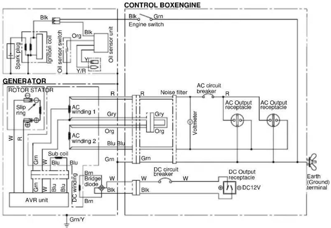
flowchart
graph TD
    subgraph CONTROL BOXENGINE
        A["Engine switch"] --> B["Blk"]
        B --> C["Blk"]
        C --> D["Organ"]
        D --> E["Oil sensor unit"]
        E --> F["Oll sensor switch"]
        F --> G["Ignition coil"]
        G --> H["Spark plug"]
        H --> I["Generator"]
        I --> J["Rotator Stator"]
        J --> K["Slip ring"]
        K --> L["AC winding 1"]
        L --> M["Gry"]
        M --> N["AC circuit breaker"]
        N --> O["Voltmeter"]
        O --> P["AC output receptacle"]
        P --> Q["AC Output receptacle"]
        Q --> R["Ground terminal"]
        R --> S["Earth (Ground) terminal"]
    end

    subgraph GENERATOR
        T["AC winding 2"] --> U["Gry"]
        U --> V["Org"]
        V --> W["Blu"]
        W --> X["Blu"]
        X --> Y["AC winding 1"]
        Y --> Z["Gry"]
        Z --> AA["Org"]
        AA --> AB["Blu"]
        AB --> AC["AC output receptacle"]
        AC --> AD["Voltmeter"]
        AD --> AE["AC output receptacle"]
        AE --> AF["AC output receptacle"]
    end

    subgraph AVR UNIT
        AG["AVR unit"] --> AH["Sub coil"]
        AH --> AI["Blu"]
        AI --> AJ["Blu"]
        AJ --> AK["AC winding"]
        AK --> AL["Brn Bridge diode"]
        AL --> AM["Brn"]
        AM --> AN["BC"]
        AN --> AO["W"]
        AO --> AP["Blk"]
        AP --> AQ["W"]
        AQ --> AR["Blk"]
        AR --> AS["W"]
        AS --> AT["DC circuit breaker"]
        AT --> AU["W"]
        AU --> AV["DC Output receptacle"]
        AV --> AW["DC12V"]
    end

    style CONTROL BOXENGINE fill:#f9f,stroke:#333
    style GENERATOR fill:#ccf,stroke:#333
    style AVR UNIT fill:#cfc,stroke:#333
Wiring color code
Blk : Black
Blk/W : Black/White
Blu : Blue
LBlu : Light blue
Brn : Brown
Brn/W : Brown/White
Grn : Green
Grn/W: Green/White
Org : Orange
Gry : Gray
R : Red
W : White
Y : Yellow
W/Blk : White/Black
Grn/Y : Green/Yellow
Pur : Purple
EG441AE, EG601AE, EG671AE (50Hz-230V) [Electric starter model]

flowchart
graph TD
    subgraph CONTROL BOXENGINE
        A["Battery"] --> B["Ignition coil"]
        B --> C["Oil sensor switch"]
        C --> D["Organ"]
        D --> E["Electric Starter"]
        E --> F["Magnetic switch"]
        F --> G["Charge coil"]
        G --> H["Blu"]
        H --> I["Gry"]
        I --> J["Grn"]
        J --> K["Blu"]
        K --> L["Blu"]
        L --> M["Blu"]
        M --> N["Blu"]
        N --> O["Blu"]
        O --> P["Blu"]
        P --> Q["Blu"]
        Q --> R["Blu"]
        R --> S["Blu"]
        S --> T["Blu"]
        T --> U["Blu"]
        U --> V["Blu"]
        V --> W["Blu"]
        W --> X["Blu"]
        X --> Y["Blu"]
        Y --> Z["Blu"]
        Z --> AA["Blu"]
        AA --> AB["Blu"]
        AB --> AC["Blu"]
        AC --> AD["Blu"]
        AD --> AE["Blu"]
        AE --> AF["Blu"]
        AF --> AG["Blu"]
        AG --> AH["Blu"]
        AH --> AI["Blu"]
        AI --> AJ["Blu"]
        AJ --> AK["Blu"]
        AK --> AL["Blu"]
        AL --> AM["Blu"]
        AM --> AN["Blu"]
        AN --> AO["Blu"]
        AO --> AP["Blu"]
        AP --> AQ["Blu"]
        AQ --> AR["Blu"]
        AR --> AS["Blu"]
        AS --> AT["Blu"]
        AT --> AU["Blu"]
        AU --> AV["Blu"]
        AV --> AW["Blu"]
        AW --> AX["Blu"]
        AX --> AY["Blu"]
        AY --> AZ["Blu"]
        AZ --> BA["Blu"]
        BA --> BB["Blu"]
        BB --> BC["Blu"]
        BC --> BD["Blu"]
        BD --> BE["Blu"]
        BE --> BF["Blu"]
        BF --> BG["Blu"]
        BG --> BH["Blu"]
        BH --> BI["Blu"]
        BI --> BJ["Blu"]
        BJ --> BK["Blu"]
        BK --> BL["Blu"]
        BL --> BM["Blu"]
        BM --> BN["Blu"]
        BN --> BO["Blu"]
        BO --> BP["Blu"]
        BP --> BQ["Blu"]
        BQ --> BR["Blu"]
        BR --> BS["Blu"]
        BS --> BT["Blu"]
        BT --> BU["Blu"]
        BU --> BV["Blu"]
        BV --> BW["Blu"]
        BW --> BX["Blu"]
        BX --> BY["Blu"]
        BY --> BZ["BLu"]
        BZ --> CA["Blu"]
        CA --> CB["Blu"]
        CB --> CC["Blu"]
        CC --> CD["BLu"]
        CD --> CE["Blu"]
        CE --> CF["Blu"]
        CF --> CG["BLu"]
        CG --> CH["Blu"]
        CH --> CI["BLu"]
        CI --> CJ["BLu"]
        CJ --> CK["BLu"]
        CK --> CL["BLu"]
        CL --> CM["BLu"]
        CM --> CN["BLu"]
        CN --> CO["BLu"]
        CO --> CP["BLu"]
        CP --> CQ["BLu"]
    end

    subgraph GENERATOR
        D["Rotor"] --> E["Slip ring"] --> F["Rotor"] & G["Ripper"] & H["Ripper"] & I["Ripper"] & J["Ripper"] & K["Ripper"] & L["Ripper"] & M["Ripper"] & N["Ripper"] & O["Ripper"] & P["Ripper"] & Q["Ripper"] & R["Ripper"] & S["Ripper"] & T["Ripper"] & U["Ripper"] & V["Ripper"] & W["Ripper"] & X["Ripper"] & Y["Ripper"] & Z["Ripper"] & AA["Ripper"] & AB["Ripper"] & AC["Ripper"] & AD["Ripper"] & AE["Ripper"] & AF["Ripper"] & AG["Ripper"] & AH["Ripper"] & AI["Ripper"] & AJ["Ripper"] & AK["Ripper"] & AL["Ripper"] & AM["Ripper"] & ANR["AVR unit"] & AO["AVR unit"] & AP["AVR unit"] & AQ["AVR unit"] & AR["AVR unit"] & AS["AVR unit"] & AT["AVR unit"] & AU["AVR unit"] & AV["AVR unit"] & AW["AVR unit"] & AX["AVR unit"] & AY["AVR unit"] & AZ["AVR unit"] & BA["AVR unit"] & BB["AVR unit"] & BC["AVR unit"] & DA["AVR unit"] & DW["AVR unit"] & DI["AVR unit"] & DV["AVR unit"] & DWA["AVR unit"]
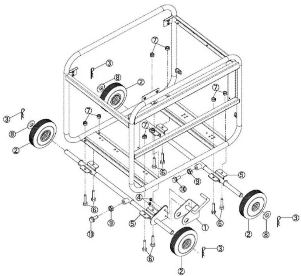
Wheel Kit Installation
(1) Check the supplied accessories
(2) Tool preparation
Orane or square bar (about 100mm by 100mm)
Pliers
sets of spanners (12mm)
(3) Installation procedures
A) Raise the generator about 100mm with the crane or square bar.
B) Install the wheel and stopper in the wheel shaft.
Install wheel shaft ⑤ into stopper ① so that wheel ② is inserted between them and fasten with pin ③.
Next, tighten wheel shaft ⑤ and stopper ① with nut ④.
Install wheel ② and washer ⑧ onto wheel shaft ⑤ and fasten with pin ③.
C) Check that the wheel rotates smoothly.
D) Loosen length adjustment nut ⑨ for wheel shaft ⑤ and bolt ⑩, then align the position of the hole on the frame with the mounting hole of wheel shaft ⑤ and tighten bolt ⑥ and nut ⑦ to fix this in place.
Tightening torque: 20 to 25N·m (2.0 to 2.5kg·m)
E) Tighten length adjustment nut ⑨ for wheel shaft ⑤ and bolt ⑩ to fix the length of wheel shaft ⑤.
VOORWOORD
INHOUD
Bladzijde
-
VEILIGHEIDSMAATREGELEN....2
-
COMPONENTEN 5
-
CONTROLES VOOR HET IN WERKING STELLEN....5
-
BEDIENINGSPROCEDURES .....7
-
INFORMATIE OVER HET VERMOGEN....11
-
VONKENVANGER 12
-
ONDERHOUDSSCHEMA 13
-
ZELF UIT TE VOEREN ONDERHOUD....14
-
PERIODIEKE HANDELINGEN EN INSPECTIES....15
-
VERVOER....15
-
VOORBEREIDINGEN VOOR OPSLAG 16
-
OPLOSSEN VAN PROBLEMEN....16
-
TECHNISCHE GEGEVENS ....17
-
BEDRADINGSSCHEMA....18
-
OPTIONELE ONDERDELEN .....20
OPMERKING
(Ah/5hr) ; 12V-21AH of meer
Afmetingen ; Minder dan 185(L) x 125(W) x 160(H) mm
② STARTKABEL (ROOD)
③ INSTELPLAAT
④ INSTELBOUT
⑤ ACCUPLAAT
⑥ ACCUFRAME #1
⑦ ACCUFRAME #2
⑧ BESCHERMPLAAT
⑨ BOUT
10 MOER
① AARDINGSKABEL (ZWART)
WAARSCHUWING
natural_image
Technical line drawing of a mechanical assembly with a coiled cable and housing (no text or symbols)natural_image
Four technical line drawings of electrical socket components, shown from different angles (front, side, top, and bottom views) without any text or symbols.WAARSCHUWING
natural_image
Line drawing of hands using a tool to adjust or install a mechanical component (no text or symbols present)Makita Corporation
3-11-8, Sumiyoshi-cho
Anjo, Aichi 446-8502 Japan

- 2
- EN
- [appendix]
- Instructions for treatment as waste
- FR
- [Annexe]
- CONTENTS
- SAFETY PRECAUTIONS
- WARNING
- CAUTION
- Symbols and Meanings
- COMPONENTS 3. PRE-OPERATION CHECKS
- (See Fig. 1) (See Fig. 2)
- NOTE
- EG241A, EG321A, EG321AE, EG441A, EG441AE (See Fig. 1-①)
- EG601A, EG601AE, EG671A, EG671AE (See Fig. 1-2)
- CHECK ENGINE OIL (See Fig. 2-①,②)
- Recommended engine oil:
- CHECK ENGINE FUEL (See Fig. 2-③,④)
- CHECKING COMPONENT PARTS
- CHECK GENERATOR SURROUNDINGS
- GROUNDING THE GENERATOR
- BATTERY INSTALLATION (See Fig. 2-7) (Electric Starter Model)
- Recommended Battery
- OPERATING PROCEDURES
- STARTING THE GENERATOR
- USING ELECTRIC POWER
- CONTROL PANEL
- AC APPLICATION
- DC APPLICATION
- DC Circuit Breaker
- Connection of exclusive DC cable :
- Battery Charging Procedures :
- STOPPING THE GENERATOR
- [Electric starter model]
- WATTAGE INFORMATION
- VOLTAGE DROP IN ELECTRIC EXTENSION CORDS
- SPARK ARRESTER
- How to remove the spark arrester
- Clean the spark arrester screen
- NOTE : (\*)
- "HOW-TO" MAINTENANCE
- ENGINE OIL CHANGE (See Fig. 5-①)
- SERVICING THE AIR CLEANER
- (See Fig. 5-② thru ④)
- CLEANING AND ADJUSTING SPARK PLUG (See Fig. 5-⑤)
- CLEANING FUEL STRAINER
- (See Fig. 5-6)
- CHECKING CARBON BRUSH
- Brush Maintenance Essentials (Effective Length)
- Brush Maintenance Essentials
- (Disassembly and Assembly) (See Fig. 5-8)
- Disassembly
- Assembly
- PERIODIC OPERATION AND INSPECTION
- TRANSPORTING
- PREPARATION FOR STORAGE
- (See Fig. 6)
- TROUBLESHOOTING
- SPECIFICATIONS
- Wheel Kit Installation
- Tightening torque: 20 to 25N·m (2.0 to 2.5kg·m)
- VOORWOORD
- INHOUD
- Bladzijde
- OPMERKING
- WAARSCHUWING
- Makita Corporation
Brand : MAKITA
Model : EG671AE
Category : Generator