
PW1550 - Pressure washer BLACK & DECKER - Free user manual and instructions
Find the device manual for free PW1550 BLACK & DECKER in PDF.


| Product Type | Pressure Washer |
| Brand | Black & Decker |
| Model | PW1550 |
| Power | 1500 W |
| Voltage | 230 V ~ 50 Hz |
| Max Pressure | 120 bar (1740 psi) |
| Working Pressure | 85 bar |
| Flow Rate | 360 L/h |
| Max Input Water Temperature | 50 °C |
| Max Inlet Pressure | 1 MPa (10 bar) |
| Weight | 8 kg |
| Motor Protection | IPX5 |
| Motor Insulation Class | F |
| Sound Level (Lpx) | 81.2 dB(A) |
| Sound Level (Lyx) | 89 dB(A) |
| Vibration Level | 3.72 m/s² |
| Gun Recoil Force (at max pressure) | 9.4 N |
| Detergent Tank | Yes (integrated) |
| Adjustable Nozzle | Yes (spray pattern adjustment) |
| Safety Features | Safety catch on gun, safety valve, pressure limiting valve |
| Included Accessories | Lance, gun, high pressure hose, detergent tank, nozzle cleaning tool, handle |
Frequently Asked Questions - PW1550 BLACK & DECKER
User questions about PW1550 BLACK & DECKER
0 question about this device. Answer the ones you know or ask your own.
Ask a new question about this device
Download the instructions for your Pressure washer in PDF format for free! Find your manual PW1550 - BLACK & DECKER and take your electronic device back in hand. On this page are published all the documents necessary for the use of your device. PW1550 by BLACK & DECKER.
USER MANUAL PW1550 BLACK & DECKER
natural_image
Line drawing of a portable electric water heater with wheels and buttons (no text or symbols)Español 7
Português 12
English 17
WARNING: READ INSTRUCTION MANUAL BEFORE USING PRODUCT.
2
1
natural_image
Illustration of hands using a tool to adjust a mechanical component, with an inset showing the same assembly (no text or symbols present)2
natural_image
Illustration of hands using a tool to adjust or install a mechanical component (no text or symbols visible)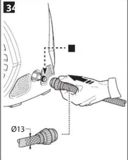
The image is too blurry to recognize any text content.
natural_image
Illustration of a hand using a tool to adjust or install a mechanical component, with no visible text or symbols.-
natural_image
Technical illustration of a mechanical assembly with hands connecting components to a motor (no text or symbols visible)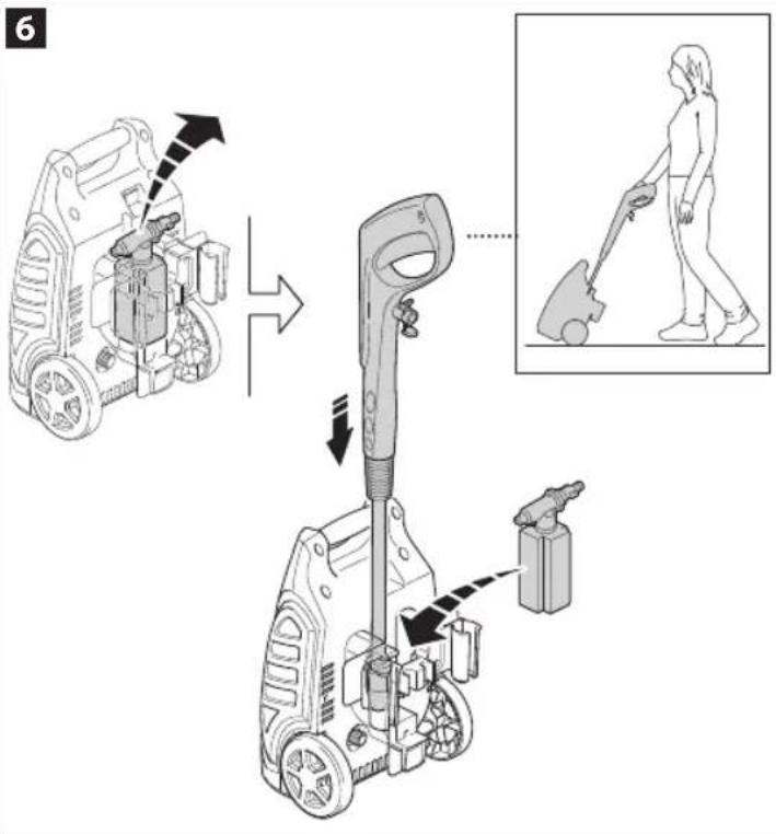
7
8
natural_image
Illustration of hands using a tool to adjust a component, no text or symbols present4
5
5

1 ÷ 25 m
25 ÷ 50 m
$$ 2 \times 1, 5 \mathrm{mm} ^ {2} $$
$$ 2 \times 2, 5 \mathrm{mm} ^ {2} $$
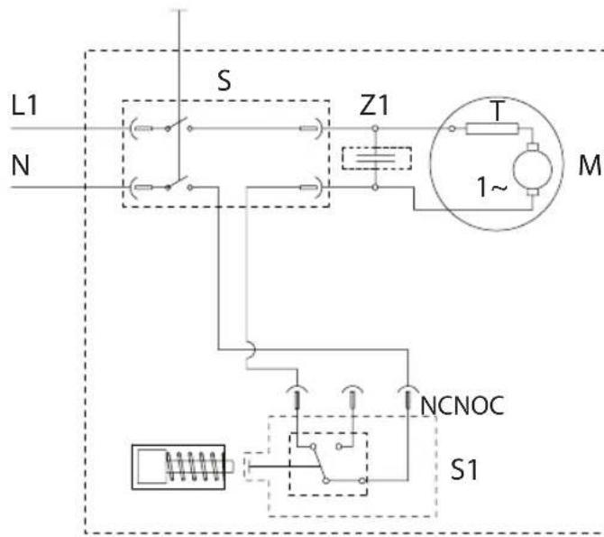
S = Interruptor/Interruptor/Switch
2
natural_image
Illustration of hands using a screwdriver to adjust a mechanical component (no text or symbols present)3
natural_image
Illustration of a hand holding a water tap with a handle (no text or symbols)4
natural_image
Illustration of a hand using a pipette to measure a small object (no text or symbols present)5
Cleaning the Water Inlet Filter
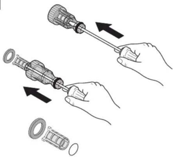
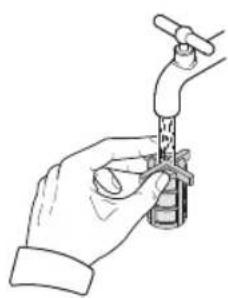
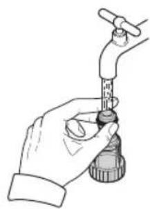
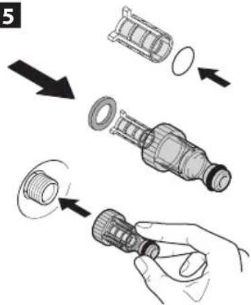
This efficient inlet filter is designed to protect your new pressure washer and ensures optimal lifetime for your machine. Before starting your pressure washer ensure the filter is clean by doing a visual check through the transparent inlet adaptor.
When should you clean the filter?
-No water comes out of the gun after inlet hose is connected and opened.
-Pressure washer does not run stable in ON position.
-Your machine cannot build up pressure.
How to clean your inlet filter
- Unscrew filter from pump inlet. (Fig. 1)
- With a screwdriver or similar object, push filter slightly from water inlet side. (Fig. 2)
- Clean filter by rinsing water through filter from the outlet side. (Fig. 3)
- Clean inlet adaptor so it stays transparent. (Fig. 4)
- Re-insert filter inside the inlet adaptor and screw it back on to the pump outlet. (Fig. 5)
Español
7
1 SAFETY INSTRUCTIONS
1.1 The appliance you have purchased is a technologically advanced product designed by one of the leading European manufacturers of high pressure pumps. To obtain the best performance from your unit, read this booklet carefully and follow the instructions each time you use it. We congratulate you on your choice and wish you successful operation.
2 SAFETY RULES
2.1 SAFETY "MUST NOTS"
2.1.1
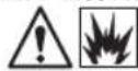

DO NOT use the appliance with inflammable or toxic liquids, or compatible with the correct operation ONING HAZARD

DO NOT direct the water jet towards people or animals. INJURY HAZARD

DO NOT direct the water jet towards the unit itself, electrical parts or towards other electrical FIC SHOCK HAZARD

DO NOT use the appliance outdoors in case of rain. SHORT CIRCUIT HAZARD

DO NOT allow children or incompetent persons to use the appliance. INJURY HAZARD

DO NOT touch the plug and/or socket with wet hands. ELECTRIC SHOCK HAZARD

DO NOT use the appliance if the electrical cable is damaged. ELECTRIC SHOCK AND SHORT CIRCUIT HAZARD

DO NOT use the appliance if the high pressure hose is damaged. EXPLOSION HAZARD

DO NOT jam the trigger in the operating position. ACCIDENT HAZARD

Check that the data plates are affixed to the appliance, if not, inform your dealer. Units without plates must NOT as they are unidentifiable and potentially dangerous. HAZARD
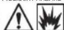
DO NOT tamper with or alter the calibration of the safety valve. EXPLOSION HAZARD

DO NOT alter the original diameter of the spray head nozzle. HAZARDOUS ALTERATION OF OPERATING PERFORMANCE

DO NOT leave the appliance unattended. ACCIDENT HAZARD

DO NOT move the appliance by pulling on the ELECTRICAL CABLE. SHORT CIRCUIT HAZARD
2.1.15 Make sure that cars do not drive over the high pressure hose.
2.2 SAFETY "MUSTS"
2.2.1
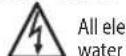
trical conductors MUST BE PROTECTED against the et. SHORT CIRCUIT HAZARD
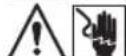
The appliance MUST ONLY BE CONNECTED to an adequate power supply in compliance with allations. ELECTRIC SHOCK HAZARD
- Use of a safety residual current circuit-breaker (R.C.C.B.) will provide additional protection for the operator (30 mA).
2.2.3
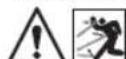

The high pressure may cause materials to bounce off surfaces
at speed; therefore protective clothing and safety goggles MUST BE WORN. INJURY HAZARD
2.2.4

Before doing work on the appliance, REMOVE the plug. ACCIDENTAL START -UP HAZARD
2.2.5

Before pressing the trigger, GRIP the gun firmly to counteract the recoil. INJURY HAZARD
2.2.6

COMPLY WITH the requirements of the local water supply company. According to DIN 1988, the appliance may only be elected to the mains drinking water supply if a backflow valve with drain facility is installed in the supply hose. NATION HAZARD
2.2.7

Maintenance and/or repair of electrical components MUST be carried out by qualified and authorized Black & Decker the warranty to take effect.
If the supply cord is damaged, it must be replaced by the manufacturer, an authorized Black & Decker Service Centre or an equally qualified person in order to avoid a hazard. If the supply cord is replaced by an equally qualified person, but not authorized by Black & Decker, the warranty will lose effect.
2.2.8

DISCHARGE residual pressure before disconnecting the unit hose. INJURY HAZARD
2.2.9

Before using the appliance, CHECK every time that the screws are fully tightened and that there are no broken or arts. ACCIDENT HAZARD
2.2.10


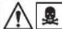
ONLY USE detergents which will not corrode the coating materials
of the high pressure hose/electrical cable. EXPLOSION AND ELECTRIC SHOCK HAZARD
2.2.11

ENSURE that all people or animals keep a minimum distance of 16 yd. (15m) away. INJURY HAZARD
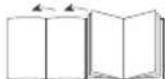
READ INSTRUCTION MANUAL BEFORE USE

18
English
3 GENERAL INFORMATION FIG.1
3.1 Use of the manual
This manual forms an integral part of the appliance and should be kept for future reference. Please read it carefully before installing/ using the unit. If the appliance is sold, the Seller must pass on this manual to the new owner along with the appliance.
3.2 Delivery
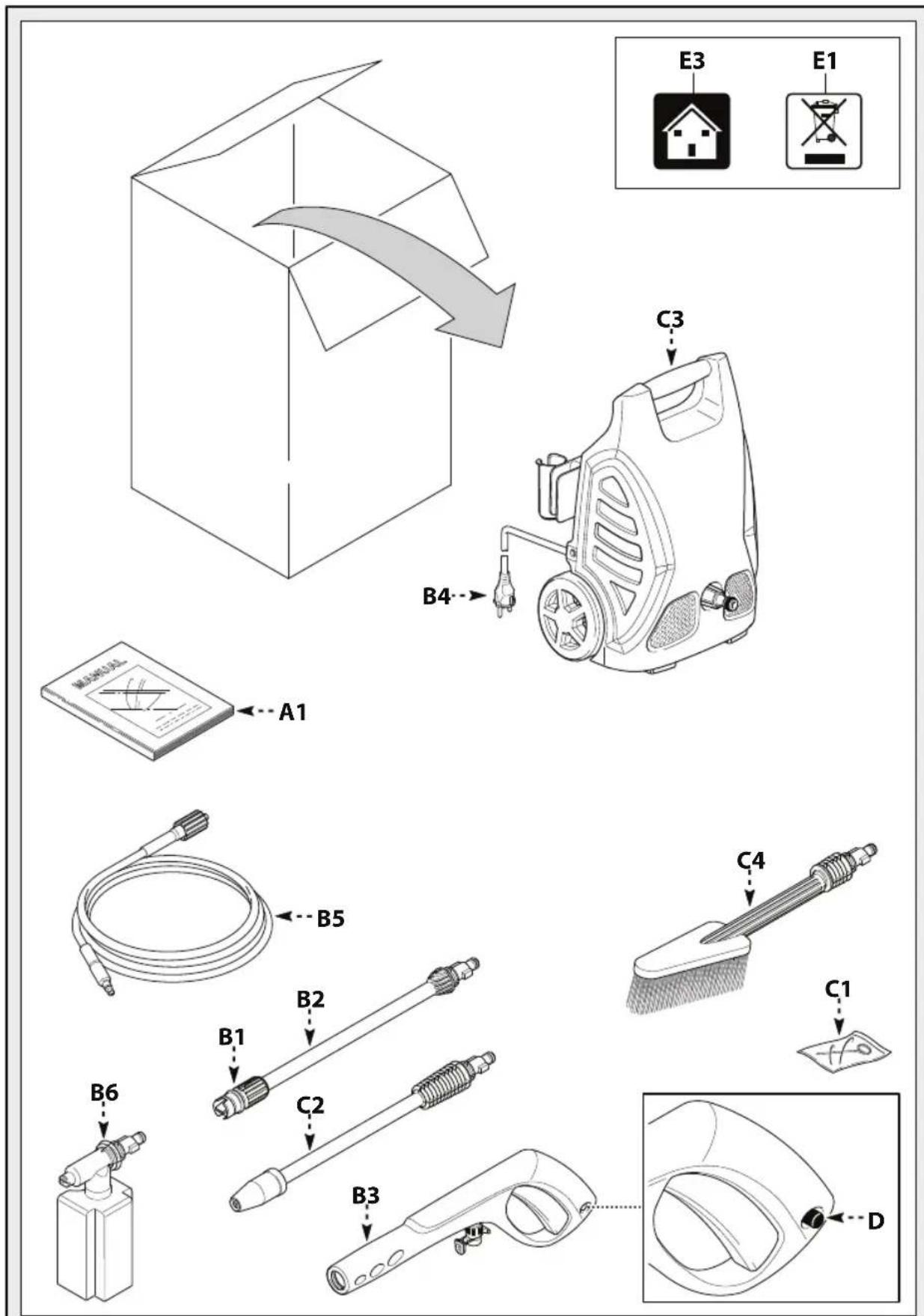
The appliance is delivered partially assembled in a cardboard box. The supply package is illustrated in fig.1.
3.2.1 Documentations supplied with the appliance A1 Use and maintenance manual
3.3 Disposing of packaging
The packaging materials are not environmental pollutants but must still be recycled or disposed of in compliance with the relevant legislation in the country of use.
3.4 Safety signs
Comply with the instructions provided by the safety signs ted to the appliance.
Check that they are present and legible; otherwise, fit replacements in the original positions.
E1 sign – Indicates that the appliance must not be disposed of as municipal waste; it may be handed in to the dealer on purchase of a new appliance. The appliance's electrical and electronic parts must not be reused for improper uses since they contain substances which constitute health hazards.
3.4.1 Symbols
E2 symbol – Indicates that the appliance is intended for professional use, i.e. for experienced people informed about the relative technical, regulatory and legislative aspects and capable of performing the operations necessary for the use and maintenance of the appliance. E3 symbol – Indicates that the appliance is intended for non-professional (domestic) use.
4 TECHNICAL INFORMATION (FG.1)
4.1 Envisaged use
This appliance has been designed for individual use for the cleaning of vehicles, machines, boats, masonry, etc, to remove stubborn dirt using clean water and biodegradable chemical detergents.
Vehicle engines may be washed only if the dirty water is disposed of as per regulations in force.
- Intake water temperature: See data plate on the appliance.
- Intake water pressure: Below 10 bar.
- Operating ambient temperature: Above 0°C.
4.2 Operator
The symbol on the front cover iden tifiethe appliance's intended operator (professional or non-professional).
4.3 Improper use
Use by unskilled persons or those who have not read and understood the instructions in the manual is forbidden.
The introduction of inflammable, explosive and toxic liquids into the appliance is prohibited.
Use of the appliance in a potentially atmosphere is forbidden.
The use of non-original spare parts and any other spare parts not specifically intended for the model in question is prohibited.
All modifications to the appliance are prohibited. Any modifications made to the appliance shall render the Declaration of Conformity null and void and relieve the manufacturer of all liability under civil and criminal law.
4.4 Main components
B1 Adjustable spray nozzle
B2 Lance
B3 Gun with safety catch
B4 Power supply cable with plug
B5 High pressure hose
B6 Detergent tank (on models with this feature)
4.4.1 Accessories(where applicable—see g.1). fi
C1 Nozzle cleaning tool
C2 Rotating nozzle kit
C3 Handle
C4 Brush
C5 Hose reel
4.5 Safety devices

Caution-Danger!
Do not tamper with or adjust the safety valve set-
ting.
- Safety valve and pressure limiting valve.
The safety valve is also a pressure limiting valve. When the gun trigger is released, the valve opens and the water recirculates through the pump inlet.
- Safety catch (D): prevents accidental spraying of water.
5 INSTALLATION (6.2)
5.1 Assembly

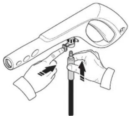
Caution-Danger!
All installation and assembly operations must be formed with the appliance disconnected from the mains supply.
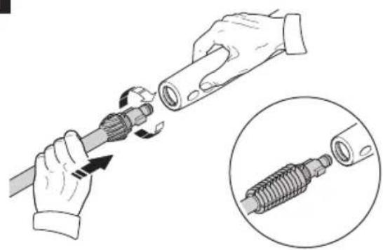
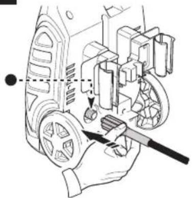
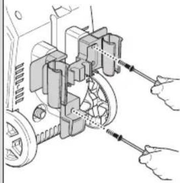
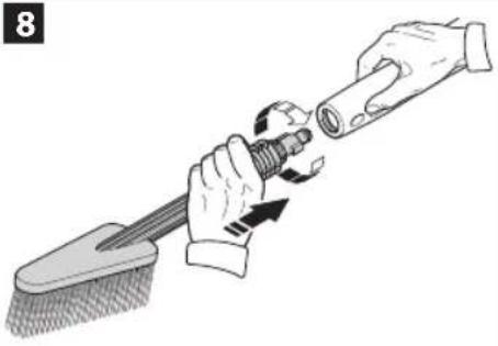
The assembly sequence is illustrated in fig.2.
5.2 Assembling the rotating nozzle
(For models with this feature)
The rotating nozzle kit delivers greater washing power.
5.3 Electrical connection

Caution-Danger!
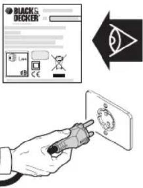
Check that the electrical supply voltage and frequency (V-Hz) correspond to those specified on the appliance data plate (fig.2). The appliance should only be connected to a mains power supply equipped with an adequate earth connection and a differential security breaker (30 mA) to cut off the electricity supply in the instance of a short circuit.
5.3.1 Useofextensioncables
Use cables featuring "IPX5" protection level.
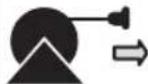
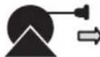
The cross-section of the extension cable should be proportionate to its length; the longer it is, the greater its cross-section should be. See table I.
5.4 Water supply connection

Caution-Danger!
Only clean or filtered water should be used for intake.
The delivery of the water intake tap should be equal to that of pump capacity.
Place the appliance as close to the water supply system as possible.
5.4.1 Connectionpoints
● Water outlet (OUTLET)
■ Water inlet with fil ter (INLET)
5.4.2 Connection to themainswatersupply
The appliance can be connected directly to the mains drinking water supply only if the supply hose is fit ted with a backflow preventer valve as per current regulations in force. Make sure that the hose is at least ∅ 13 mm and that it is reinforced.
English
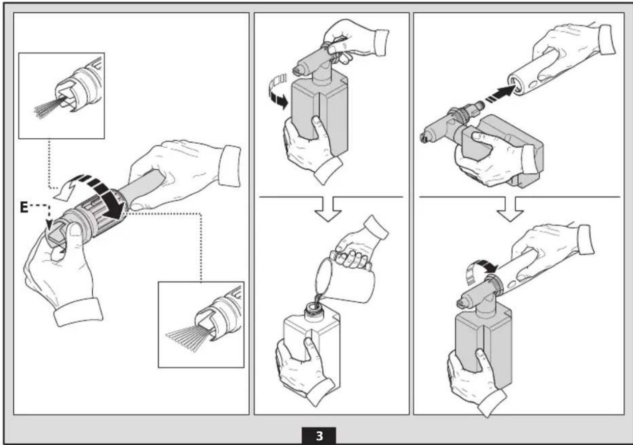
6 ADJUSTMENT INFORMATION (FIG.3)
6.1 Adjusting the spray nozzle (for models with this feature) Water flow is adjusted by regulating the nozzle (E) .
6.2 Adjusting the detergent (on models with this feature) Detergent flow is adjusted using the regulator (F).
6.3 Adjusting the detergent pressure Set the adjustable nozzle on "■ to deliver detergent at the correct pressure (on models with this feature).
6.4 Adjusting the pressure (on models with this feature) The regulator (G) is used to adjust the working pressure. The pressure is shown on the pressure gauge (where fitted).
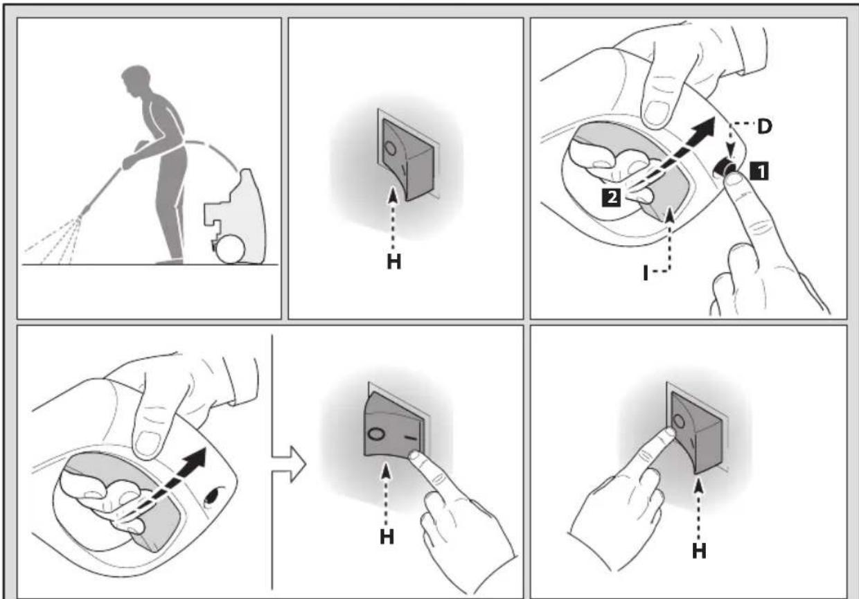
7 INFORMATION ON USE OF THE APPLIANCE (FIG.4)
7.1 Controls
- Starter device (H).
Set the starter switch on (ON/1) to:
a) start the motor (in models without AS device);
b) set the motor ready to start (in models with AS device).
If there is a pilot light on the starter device, it should light up.
If the "low/high" settings are available, use them as follows:
Low : low pressure washing
High : high pressure washing
Set the starter device switch on (OFF/0) to shut down the appliance.
If there is a pilot light on the starter device, it should go out.
- Water jet control lever (I).
Caution - Danger! During operation the appliance must be positioned as shown in fig. 4 on a sturdy, stable surface.
7.2 Start-up
Caution - Danger! Before starting up the appliance check that the water supply hose is connected properly; use of the appliance without water will damage it; do not cover the ventilation grilles when the appliance is in use.
1) Turn on the water supply tap fully.
2) Release the safety catch (D).
3) Depress the gun trigger for a few seconds and start up the appliance using the starter device (ON/1).
AS models - In AS models with automatic delivery flow cut-off system:
- When the gun trigger is released the dynamic pressure automatically cuts out the motor (see fig.4);
- When the gun trigger is depressed the automatic drop in pressure starts the motor and the pressure is restored after a very slight delay;
- If the AS is to function correctly all gun releasing and depressing operations must be performed at intervals of less than 4-5 seconds.
To prevent damage to the appliance, when running do not stop the water jet for more than 10 minutes at a time.
7.3 Stopping the appliance
1) Set the starter device switch on (OFF/0).
2) Depress the gun trigger and discharge the residual pressure inside the hoses.
3) Engage the gun safety catch (D).
7.4 Restarting
1) Release the safety catch (D).
2) Depress the gun trigger and discharge the residual air inside the hoses.
3) Set the starter device on (ON/1).
7.5 Storage
1) Switch the appliance off (OFF/0).
2) Remove the plug from the socket.
3) Turn off the water supply tap.
4) Discharge the residual pressure from the gun until all the water has come out of the nozzle.
5) Drain the detergent tank.
6) Engage the gun safety catch (D).
7.6 Refilling and using detergent
When using detergent, the adjustable nozzle must be set on "—on models with this feature).
Fill the tank with highly degradable detergent.
7.7 Recommended cleaning procedure
Dissolve dirt by applying the detergent mixed with water to the surface while still dry.
When dealing with vertical surfaces work from the bottom upwards. Leave the detergent to act for 1-2 minutes but do not allow the surface to dry. Starting from the bottom, use the high pressure jet at a minimum distance of 30~cm . Do not allow the rinse water to run onto unwashed surfaces.
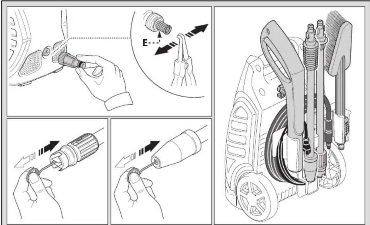
8 MAINTENANCE (FIG.5)
Any maintenance operations not covered by this chapter should be carried out by an Authorized Sales and Service Centre.
Caution - Danger! Always disconnect the plug from the power socket before carrying out any work on the appliance.
8.1 Cleaning the nozzle
1) Disconnect the lance from the nozzle.
2) Remove any dirt deposits from the nozzle hole using the tool (C1).
8.2 Cleaning the filter
Clean the suction filter (L) and the detergent filter after every 50 hours of operation.
8.3 Unjamming the motor (on models with this feature)
In case of lengthy stoppages, limescale sediments may cause the motor to seize. To unjam the motor, turn the drive shaft with a tool (M).
8.4 End-of-season storage
Treat the appliance with non-corrosive, non-toxic antifreeze before storing it away for winter.
20
English
9 TROUBLESHOOTING
| Problem Possible causes Remedy | ||
| Pump does not reach working pressure | Nozzle worn Replace nozzle | |
| Water filter fouled Clean filter (fig.5) | ||
| Water supply pressure low Turn on water supply tap fully | ||
| Air being sucked into system Check tightness of hose fittings | ||
| Air in pump | Switch off the appliance and keep depressing and releasing the gun trigger until the water comes out in a steady flow. Switch the appliance back on again. | |
| Adjustable nozzle not positioned correctly Turn the adjustable nozzle (E) (+) (fig.3) | ||
| Pressure drops during use | Water intake from external tank Connect appliance to the mains water supply | |
| Intake water too hot Reduce temperature | ||
| Nozzle clogged Clean nozzle (fig.5) | ||
| Motor “sounds” but fails to start | Insufficient power supply | Check that the voltage of the mains power supply line is the same as that on the plate (fig.2) |
| Voltage loss due to use of extension cable Check characteristics of extension cable | ||
| Appliance not used for a long period of time Contact your nearest Authorized Service Centre | ||
| Problems with AS device | Contact your nearest Authorized Service Centre | |
| Motor fails to start | No electrical power | Check that the plug is firmly in the socket and that the mains voltage supply is present (*) |
| Problems with AS device | Contact your nearest Authorized Service Centre | |
| Appliance not used for a long period of time | Using the tool (L) unjam the motor from the hole at the rear of the appliance (in models with this feature) (fig.5) | |
| Water leakage | Seals worn | Have the seals replaced at your nearest Authorized Service Centre |
| Appliance noisy | Water too hot | Reduce temperature (see technical data |
| Oil leakage | Seals worn | Contact your nearest Authorized Service Centre |
| AS versions only: motor starts even with gun trigger is released | Nozzle clogged Clean nozzle (fig.5) | |
| High pressure system or pump hydraulic circuit not watertight | Contact your nearest Authorized Service Centre | |
| AS versions only: no water delivery when gun trigger is depressed (with supply hose connected) | Nozzle clogged Clean nozzle (fig.5) | |
If the motor starts and does not restart during operation, wait 2-3 minutes before repeating the start-up procedure (overload cutout has been tripped). If the problem recurs more than once, contact your nearest Authorized Service Centre.
21English
| Technical Data Unit | PW1550 | |
| Output | L/h | 360 |
| Pressure | Bar | 85 |
| MPa | 8,5 | |
| Maximum pressure | Bar | 120 |
| MPa | 12 | |
| Power | W | 1500 |
| T° input | °C | 50 |
| Maximum input pressure | MPa | 1 |
| Repulsive force of the gun to the maximum pressure | N | 9,4 |
| Motor Insulation | - | Class F |
| Motor Protection | - | IPX5 |
| VoltageAR 230V~50HzB2C 220V~50HzB2 220V~60HzB3 120V~60HzBR 127V~60Hz | ||
| Sound level:Lpx(EN 60704-1)Lyx(EN 60704-1) | Db (A)Db (A) | 81,289 |
| Unit vibrations | M/s ^2 | 3,72 |
| Weight | kg | 8 |
10 SERVICE
Black & Decker offers a full network of company-owned and authorized service locations. All Black & Decker Service Centers are staffed with trained personnel to provide customers with efficient and reliable power tool service. Whether you need technical advice, repair, or genuine factory replacement parts, contact the Black & Decker location nearest you.
CNPJ: 53.296.273/0001-91
Insc. Est.: 701.948.711.00-98
S.A.C.: 0800-703-4644
- Cleaning the Water Inlet Filter
- When should you clean the filter?
- How to clean your inlet filter
- Español
- SAFETY INSTRUCTIONS
- SAFETY RULES
- SAFETY "MUST NOTS"
- SAFETY "MUSTS"
- English
- GENERAL INFORMATION FIG.1
- Use of the manual
- Delivery
- Disposing of packaging
- Safety signs
- Symbols
- TECHNICAL INFORMATION (FG.1)
- Envisaged use
- Operator
- Improper use
- Main components
- B2 Lance
- Safety devices
- Caution-Danger!
- Do not tamper with or adjust the safety valve set-
- ting.
- INSTALLATION (6.2)
- Assembly
- Assembling the rotating nozzle
- Electrical connection
- Useofextensioncables
- Water supply connection
- Connection to themainswatersupply
- ADJUSTMENT INFORMATION (FIG.3)
- INFORMATION ON USE OF THE APPLIANCE (FIG.4)
- Controls
- Start-up
- Stopping the appliance
- Restarting
- Storage
- Refilling and using detergent
- Recommended cleaning procedure
- MAINTENANCE (FIG.5)
- Cleaning the nozzle
- Cleaning the filter
- Unjamming the motor (on models with this feature)
- End-of-season storage
- SERVICE
Brand : BLACK & DECKER
Model : PW1550
Category : Pressure washer