
CJ-7500E - Dashboard camera CLARION - Free user manual and instructions
Find the device manual for free CJ-7500E CLARION in PDF.


| Product Type | Dashboard Camera |
| Brand | Clarion |
| Model | CJ-7500E |
| Dimensions | Approximately 6.5 x 4 x 2 cm |
| Weight | Approximately 100 g |
| Power Source | USB 5V DC |
| Power Consumption | Approximately 2.5 W |
| Battery | Built-in rechargeable Li-ion battery (around 200 mAh) |
| Video Resolution | Full HD 1080p (1920 x 1080) |
| Field of View | 140° wide angle lens |
| Frame Rate | Up to 30 fps |
| Storage Medium | MicroSD card (up to 64 GB, Class 10 recommended) |
| Loop Recording | Yes, with automatic overwrite of oldest files |
| G-Sensor | Built-in accelerometer for impact detection and event lock |
| Night Vision | Yes, with infrared LEDs |
| Parking Mode | Supported (requires hardwire kit, sold separately) |
| Display | 2.0 inch TFT color screen |
| Mounting | Adhesive windshield mount |
| Maintenance | Clean lens with a soft, dry cloth; avoid solvents |
| Safety | Do not expose to extreme temperatures or direct sunlight for prolonged periods; keep away from children. |
| Spare Parts | Replacement windshield mount, USB cable, car charger (12-24V to 5V), mounting adhesive pads |
| Repairability | Non-user-serviceable; contact Clarion support for repairs |
| General Information | User manual available for free download at notice-facile.com in PDF format (24 pages, English). |
Frequently Asked Questions - CJ-7500E CLARION
User questions about CJ-7500E CLARION
0 question about this device. Answer the ones you know or ask your own.
Ask a new question about this device
Download the instructions for your Dashboard camera in PDF format for free! Find your manual CJ-7500E - CLARION and take your electronic device back in hand. On this page are published all the documents necessary for the use of your device. CJ-7500E by CLARION.
USER MANUAL CJ-7500E CLARION
Owner's manual & Installation manual
CJ-7500E
7" WATERPROOF WIDESCREEN DIGITAL QUAD COLOR MONITOR

CONTENTS
- SAFETY INSTRUCTIONS.... 3 \~ 4
- BEFORE USE....5
- FEATURES....6
- CONTENTS 6
- BUTTON FUNCTIONS....7
- FUNCTIONS....8 \~ 15
[1] POWER ON / STAND-BY 8
[2] VOLUME CONTROL 8
[3] SCREEN SWITCH 8
[4] SELECT SPLIT MODE 9
[5] CAMERA SELECTION 9\~10
[6] CAMERA MIRROR/NORMAL MODE SETTING 11
[7] ON SCREEN DISTANCE MARKER SETTING 12 \~ 13
[8] SCREEN SWITCHING USING TRIGGER INPUTS.... 13 \~ 15
- SETTINGS.... 16 \~ 17
[1] VIDEO STANDARD SYSTEM, NTSC/PAL SELECTION 16
[2] DIMMER SENSOR SETTING 16
[3] PICTURE SETUP 16
[4] LANGUAGE SETTING....17
[5] INITIALIZATION 17
- INSTALLATION 18
- CONNECTIONS.... 19
- TROUBLESHOOTING....20
1 1. SPECIFICATIONS....20
This unit has been tested and found to comply with the limits for a Class B digital device, pursuant to Part 15 of the FCC Rules.
These limits are designed to provide reasonable protection against harmful interference in a residential installation.
This unit generates, uses, and can radiate radio frequency energy, and, if not installed and used in accordance with the instructions, may cause harmful interference to radio communications.
However, there is no guarantee that interference will not occur in a particular installation.
If this unit does cause harmful interference to radio or television reception, which can be determined by turning the equipment off and on, the user is encouraged to consult the dealer or an experienced radio/TV technician for help.
■INFORMATION FOR USERS: CHANGES OR MODIFICATIONS TO THIS PRODUCT NOT APPROVED BY THE MANUFACTURER WILL VOID THE WARRANTY AND WILL VIOLATE FCC APPROVAL.

■Declaration of conformity
We Clarion declares that the product CJ-7500 is following the provision of Directive 2004/108/EC and Directive 2011/65/EU with the essential requirements and the other relevant regulations.
Clarion Europe SAS
facsimile: +33(0)3 83 49 45 99
1. SAFETY INSTRUCTIONS
Please read the "Safety Rules" carefully before using this product. Following the safety rules prevents users from damages related with the misuse of the product. It is very important to follow these safety rules. We state "Caution" and "Warning" to clarify any potential risk of damage associated with the misuse of the product.
 WARNING WARNING | This information is for preventing bodily harm or even death and user should follow these safety rules. |
 CAUTION CAUTION | This information is for preventing damage or shortening the life time of the products. |
 ATTENTION ATTENTION | This information is for user's reference for better usability. |

WARNING
- Do not install the monitor in effective range of air bags.

It may cause malfunction of air bag or injury in the event of an accident deploy in the air bag.
- Do not use if smoke is seen or unit emits burning smell.

It may cause fi re. Discontinue use and contact place of purchase.

- Do not disassemble, repair or modify.
It may cause malfunction or injury and may void warranty. Make inquiries to place of purchase for repair and checkup.

- Do not reverse vehicle while relying only on the monitor image.

● Drive slowly when reversing.

CAUTION
- Disconnect battery before installation. Re-connect once installation is complete.
Prevents electric shock or short circuit.
- Do not use for long periods without engine running.
It may cause battery to go fl at.
- The rear-view monitor image has the same right-left inversion as your vehicle's rearview mirrors. Depending on the vehicle, the field and angle of view may differ.
- Do not use multi socket or extended adaptor.
It may cause unexpected overheating, fire and malfunction.
● Unplug product when not in use for a long time.
It may cause fire by short circuit due to overheating.
- Do not place near magnet.
It may cause malfunction or picture distortion.


2. BEFORE USE
Precautions (when you use the monitor)
● Use the product at the temperature range of -10^ 60^ .
- Screen may be a little dark when the product is operated in low temperature areas. Screen will show normal luminosity after a few minutes.
- Do not disassemble and modify the product in any way. This may cause fire and/or electric shock.
- When you install the product in a vehicle and watch the monitor, the car engine should be running to avoid fl attening the battery.
Precautions (when you use the product in a vehicle)
● The driver should not use the product while he/she is driving.
● Be cautious of shock when you use the product in a vehicle.
- Cover the product when exposed to direct rays of the sun for a long period of time. (You should keep the product at a temperature range of -20^ 70^ .)
3. FEATURES
- 7" WVGA (800x480) LCD panel
• Water resistant (IP67), Aluminum housing
• 8 language display selection (English-French-German-Italian-Spanish-Swedish-Chinese-Japanese) - DC12\~24V
- Max.4 camera input
- Camera input screen inversion (Normal/Mirror mode)
- User can choose split screen (2/3/4 Split screen)
- Dimmer sensor is built-in
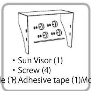
4. CONTENTS
* When opening the gift box, please check the contents listed below. If you find parts are missing, please contact place of purchase.
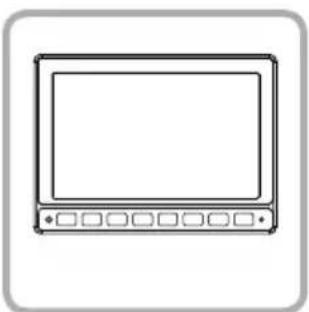
natural_image
Simple line drawing of a monitor with control buttons at the bottom (no text or symbols)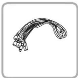
natural_image
Illustration of a curved cable or connector with multiple connectors (no text or symbols)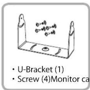
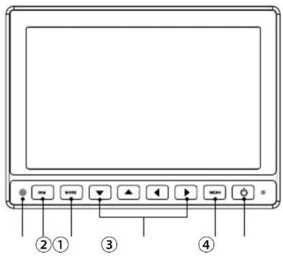
5. BUTTON FUNCTIONS
[Monitor]
natural_image
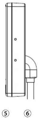
Technical line drawing of a vertical cylindrical component with two circular holes, labeled ⑤ and ⑥ (no text or symbols on the diagram itself)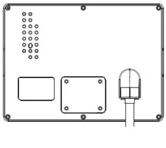
natural_image
Technical line drawing of a device panel with mounting holes and a central display unit (no text or symbols)| 1. DIMMER SENSOR | Automatic brightness control sensor |
| 2. DIM | DIMMER |
| 3. MODE | Switch Screen / Select SUB-MENU |
| 4. ▼▲◀▶ | DOWN/UP/LEFT/RIGHT |
| 5. MENU | Switch Main Menu |
| 6. POWER | Power ON/Stand-by |
6. FUNCTIONS
1 POWER ON/OFF
Press [💡] button then the picture from the cameras will be shown on the monitor.
Press [💡] button again to switch off.
* If there is no camera video input, the screen will remain Black.
* Factory default setting shows 4 way split screen.
| CAM1 CAM4 | |
| CAM3CAM2 |
2 VOLUME CONTROL
Press [◀▶] button to control volume(0\~100).
Volume control works only in CAM1 screen.
* Factory default Volume setting is 30.
VOLUME 30
③ SCREEN SWITCH
Press [MODE] button on monitor, then the screen switches in the following order.
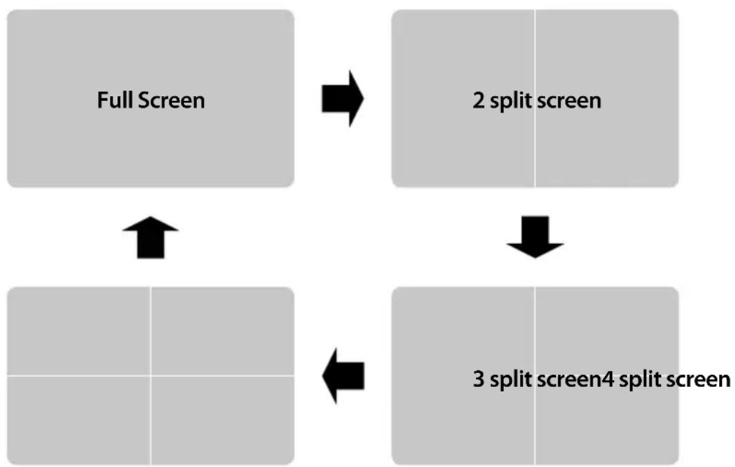
flowchart
graph TD
    A["Full Screen"] --> B["2 split screen"]
    B --> C["3 split screen4 split screen"]
    C --> D["Next Step"]
    D --> E["Next Step"]
    E --> F["Next Step"]
    F --> G["Next Step"]
    G --> H["Next Step"]
    H --> I["Next Step"]
    I --> J["Next Step"]
    J --> K["Next Step"]
    K --> L["Next Step"]
    L --> M["Next Step"]
    M --> N["Next Step"]
    N --> O["Next Step"]
    O --> P["Next Step"]
    P --> Q["Next Step"]
    Q --> R["Next Step"]
    R --> S["Next Step"]
    S --> T["Next Step"]
    T --> U["Next Step"]
    U --> V["Next Step"]
    V --> W["Next Step"]
    W --> X["Next Step"]
    X --> Y["Next Step"]
    Y --> Z["Next Step"]
4 SELECT SPLIT MODE
Each split screen has two options. In split mode, press [▼ ▲] button then the screen switches between both options.
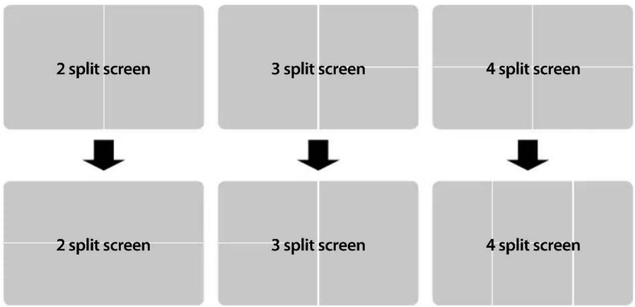
flowchart
graph TD
    A["2 split screen"] --> B["2 split screen"]
    C["3 split screen"] --> D["3 split screen"]
    E["4 split screen"] --> F["4 split screen"]
⑤ CAMERA SELECTION
1) FULL SCREEN MODE
In full screen mode, press [▼▲] button then the screen switches in the following order.
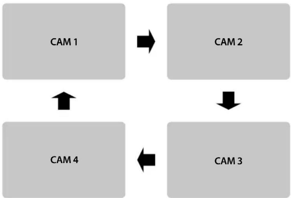
flowchart
graph TD
    A["CAM 1"] --> B["CAM 2"]
    B --> C["CAM 3"]
    C --> D["CAM 4"]
    D --> A
Press [MENU] button, then it displays screen information (Input mode / Volume).
2) 2 SPLIT SCREEN MODE
Press [MENU] button to go to 「SPLIT SCREEN SETUP」.
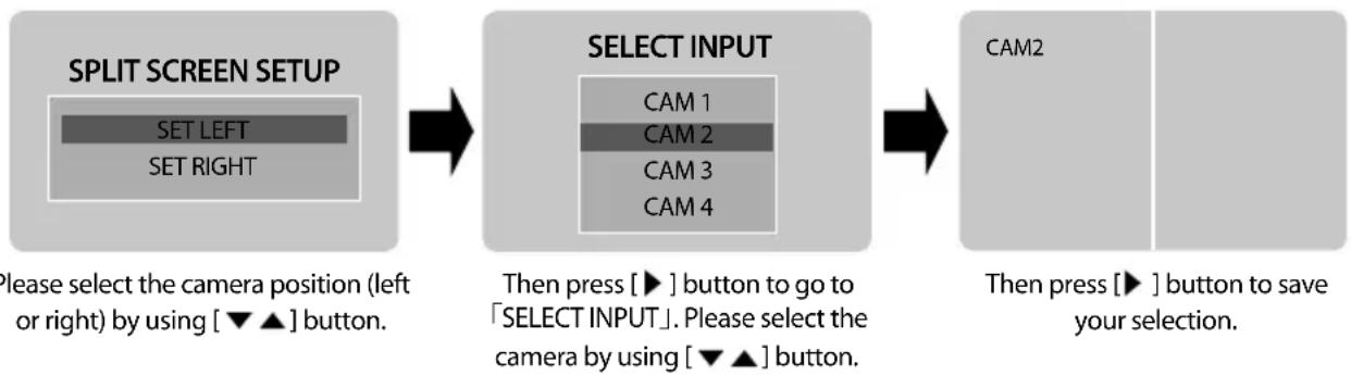
flowchart
graph LR
    A["SPLIT SCREEN SETUP"] --> B["SELECT INPUT"]
    B --> C["CAM2"]
    style A fill:#f9f,stroke:#333
    style B fill:#ccf,stroke:#333
    style C fill:#cfc,stroke:#333
3) TRIPLE SPLIT SCREEN MODE
Press [MENU] button to go to 「TRIPLE SCREEN SETUP」.
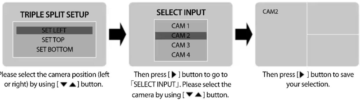
flowchart
graph LR
    A["TRIPLE SPLIT SETUP"] --> B["SELECT INPUT"]
    B --> C["CAM2"]
    style A fill:#f9f,stroke:#333
    style B fill:#ccf,stroke:#333
    style C fill:#cfc,stroke:#333
4) QUAD SCREEN MODE
Press [MENU] button to go to 「QUAD SCREEN SETUP」.
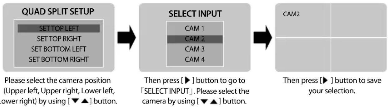
flowchart
graph LR
    A["QUAD SPLIT SETUP"] --> B["SELECT INPUT"]
    B --> C["CAM2"]
    style A fill:#f9f,stroke:#333
    style B fill:#ccf,stroke:#333
    style C fill:#dfd,stroke:#333
Repeat these steps to set each camera's position.
6 CAMERA MIRROR/NORMAL MODE SETTING
1) CAM1 full screen
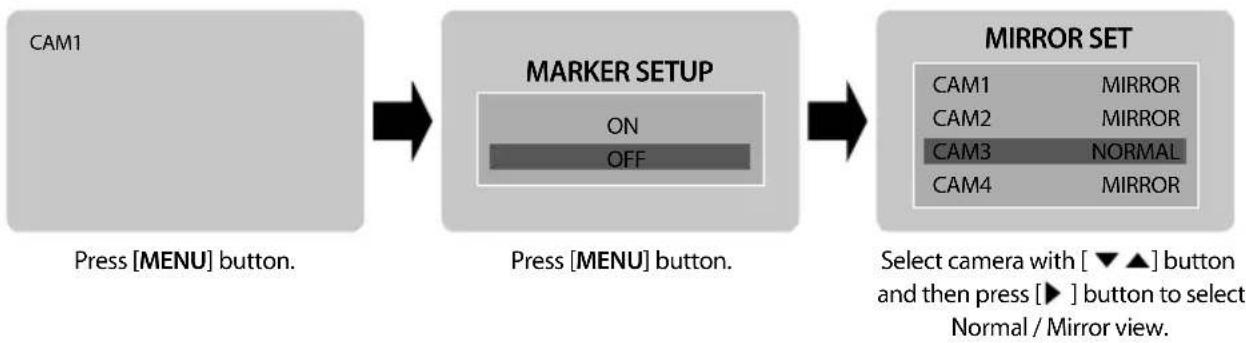
flowchart
graph LR
    A["CAM1"] --> B["Press [MENU"] button.]
    B --> C["MARKER SETUP"]
    C --> D["Press [MENU"] button.]
    D --> E["MIRROR SET"]
    E --> F["Select camera with [▼ ▲"] button_and_then_press["► "] button to select Normal / Mirror view.]
2) CAM2 or CAM3 full screen
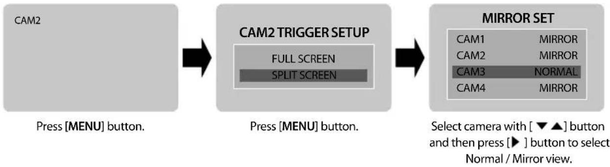
flowchart
graph LR
    A["CAM2"] --> B["CAM2 TRIGGER SETUP"]
    B --> C["MIRROR SET"]
    A -->|Press["MENU"] button.| B
    B -->|Press["MENU"] button.| C
    C -->|Select_camera_with["▼▲"] button_and_then_press["▶"] button to select Normal / Mirror view.| D["Normal / Mirror view."]
3) CAM4 full screen
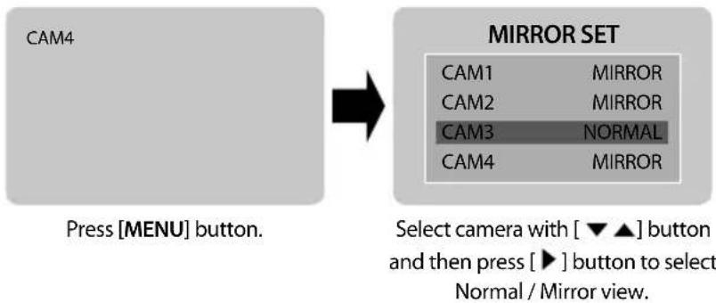
flowchart
graph LR
    A["CAM4"] --> B["Press [MENU"] button.]
    B --> C["MIRROR SET"]
    C --> D["Select camera with [▼▲"] button_and_then_press["▶"] button to select Normal / Mirror view.]
    D --> E["Mirror Set"]
4) Split screen (2/3/4)
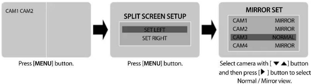
flowchart
graph LR
    A["Press [MENU"] button.] --> B["SPLIT SCREEN SETUP"]
    B --> C["MIRROR SET"]
    C --> D["Select camera with [▼▲"] button_and_then_press["▶"] button to select Normal / Mirror view.]

ON SCREEN DISTANCE MARKER SETTING

Warning
- The onscreen distance markers should be considered as a general reference to assist the driver in assessing the distances depicted on the screen. The distance markers have been designed based on the "CCD camera installation conditions" listed in the next section, but differences in vehicle design and construction may result in the actual installation condition or location being different from the conditions listed. In such cases, the display location should be set at the closest marker No.
- Distance markers cannot be set if non Clarion cameras are used.

Caution
- The markers may not indicate the exact position of the bumper, the vehicle's width or the distance to the rear. Use as a reference only.
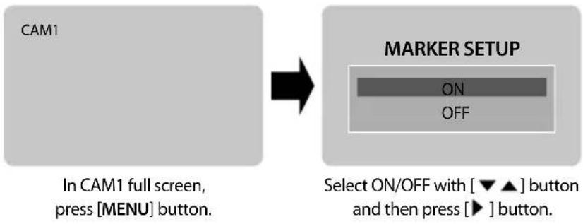
flowchart
graph LR
    A["CAM1\nIn CAM1 full screen, press [MENU"] button.] --> B["MARKER SETUP\nON\nOFF\nSelect ON/OFF with [▼▲"] button_and_then_press["►"] button.]
1) MARKER SELECTION
- Press [MENU] button four times, and select MARKER SETUP menu.
- Press [◀ ▶ ] button, and switch marker pattern.
* Distance marker function setting is only possible when MARKER SETUP ON is selected on CAM1, full screen mode.
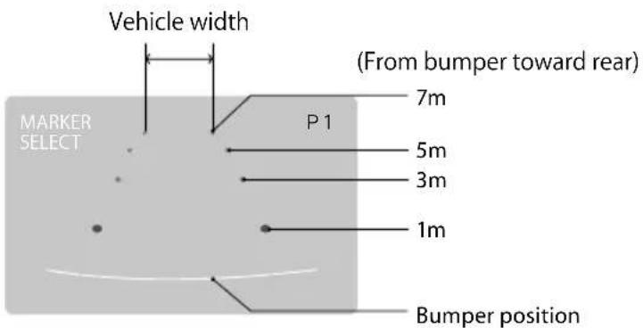

CCD camera installation conditions (distance marker input conditions)
(Unit : mm)
| Marker No. (Pattern) | Camera Install Height | Vehicle Width |
| P1 | 2,000 | 2,500 |
| P2 | 2,250 | 2,300 |
| P3 | 2,500 | |
| P4 | 2,750 | |
| P5 | 3,000 | |
| P6 | 3,250 | |
| P7 | 3,500 | 2,500 |
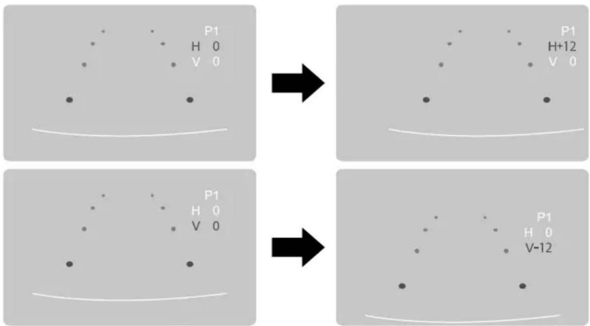
2) MARKER ADJUSTMENT (Adjusting the bumper position)
- Press [MENU] button five times, and select MARKER ADJUST menu.
- Press [▼▲] button, and select H/V. (H: horizontal / V: vertical)
- Press [◀ ▶] button, and switch marker pattern.
(H = -12 \~ +12, V = -12 \~ +12, Default setting: H = 0, V = 0)
- After 10 seconds, set up screen disappears, and set up finishes.
* If there is no button operation, set up screen disappears even during set up process.
⑧ Automatic Screen switching using Trigger inputs
* Below example is set with TRG1(Reverse gear)=CAM1 / TRG2(Left turn signal)=CAM2 / TRG3(Right turn signal)=CAM3.
1) If there is a trigger signal input, the connected camera is displayed as full screen and switches back when the signal switches off.
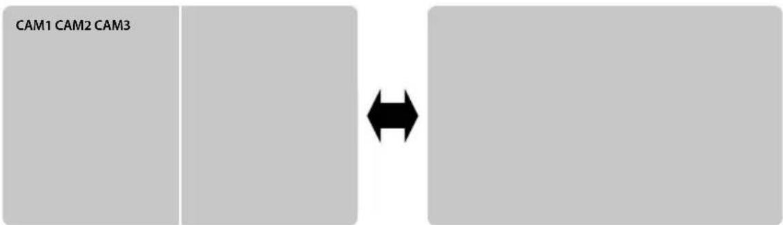
2) In case of TRG2 (Left turn signal) or TRG3 (Right turn signal), you can choose full screen or split screen by OSD setting.
* This function is for showing not only Left(Right) but also rear view together at the same time, regardless of former screen status. It displays CAM2(3) and CAM1 as split screen when TRG2(3) signal input is on.

flowchart
graph LR
    A["CAM2 CAM1"] --> B["CAM2 TRIGGER SETUP"]
    B --> C["CAM2"]
    B --> D["FULL SCREEN"]
    B --> E["SPLIT SCREEN"]
In CAM2 full screen, press [MENU] button to see OSD. Select split screen with [▼▲] button and then press [▶] button. If there is left signal input(TRG2), then CAM2(Left) in left side and CAM1(Rear) in right side will be shown on the screen.

flowchart
graph LR
    A["CAM3 CAM3"] --> B["CAM3 TRIGGER SETUP"]
    B --> C["CAM1"]
    B --> D["FULL SCREEN\nSPLIT SCREEN"]
In CAM3 full screen, press [MENU] button to see OSD. Select split screen with [▼▲] button and then press [▶] button. If there is right signal input(TRG3), then CAM1(Rear) in left side and CAM3(Right) in right side will be shown on the screen.
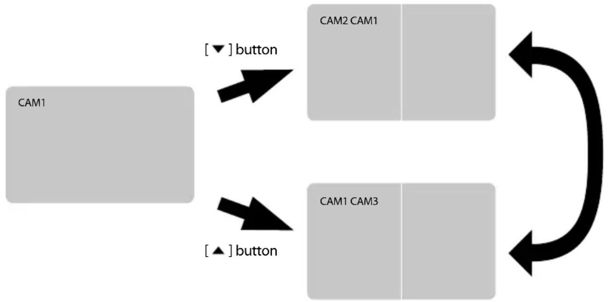
3) When there is the TRG1(Reverse gear) input, CAM1 video will be shown on the screen. Using [▼▲] button, the 2 split screen of CAM2/CAM1 or CAM1/CAM3 can be displayed.
flowchart
graph TD
    A["CAM1"] -->|[▼] button| B["CAM2 CAM1"]
    A -->|[▲] button| C["CAM1 CAM3"]
    B --> D[" "]
    C --> E[" "]
    D <--> F[" "]
    E <--> G[" "]
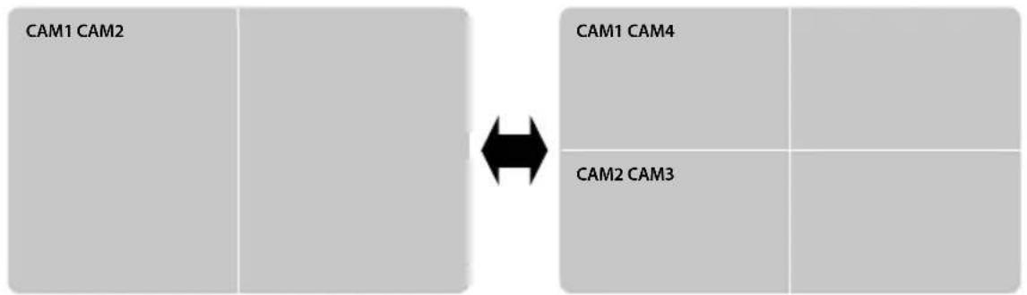
4) In case of a hazard flasher trigger(TRG2+TRG3), the monitor displays CAM1\~CAM4 as quad split screen. The screen switches back when the hazard flasher trigger is switched off.
flowchart
graph LR
    A["CAM1 CAM2"] --> B["Cam1 CAM4"]
    C["CAM2 CAM3"] --> D["Cam2 CAM4"]

The example is set with TRG1(Reverse gear)=CAM1 / TRG2(Left turn signal)=CAM2 / TRG3(Right turn signal)=CAM3
5) When more than two trigger signals are received at once, the monitor will display the highest priority trigger. As triggers are removed, screen will show next highest priority trigger (see priority order below).

TRIGGER PRIORITY ORDER TRG1(Reverse gear) > TRG2+3(Hazard flasher) > TRG2(Left turn signal) > TRG3(Right turn signal)
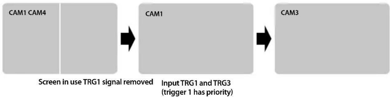
flowchart
graph LR
    A["CAM1 CAM4"] --> B["CAM1"]
    B --> C["CAM3"]
    note["Screen in use TRG1 signal removed"] --> B
    note["Input TRG1 and TRG3 (trigger 1 has priority)"]
* During the time that trigger is activated, [west menu] buttons don't work.
* In standby status if the trigger wire is activated the monitor will turn on. The screen will turn off once the power is de-activated to the trigger wire. And the screens turns off when the trigger signal switches off.
7. SETTINGS
1 VIDEO STANDARD SYSTEM NTSC/PAL SELECTION
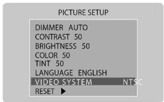
1) Press [MENU] button until OSD menu [PICTURE SETUP] appears.
2) Press [▼▲] button to move a to VIDEO SYSTEM and choose video system by pressing [◀▶] button.

Please select NTSC for video system as Clarion cameras are compatible with NTSC video system.
2 DIMMER SENSOR SETTING
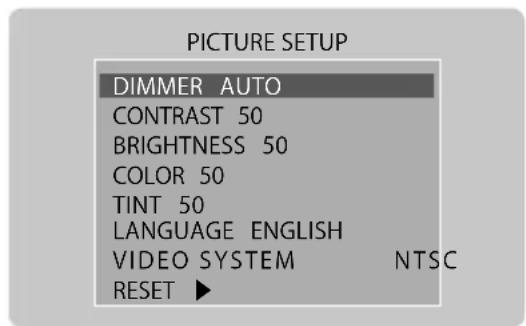
1) Press [MENU] button until OSD menu [PICTURE SETUP] appears.
2) Press [▼▲] button to move to DIMMER and choose proper value, DAY(brighter)/NIGHT(Darker)/AUTO(Sensor) by pressing [◀▶] button.
Press [DIM] button to switch DAY -» NIGHT -» AUTO -» DAY.
* Factory default setting is AUTO.
3 PICTURE SETUP
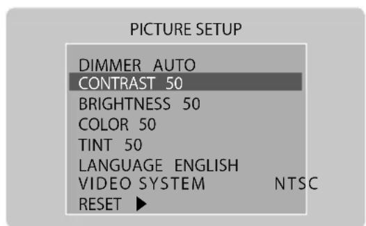
1) Press [MENU] button until OSD menu [PICTURE SETUP] appears.
2) Press [▼▲] button to move to each menu and choose proper value by pressing [◀▶] button.
* Factory default setting value is 50.
4 LANGUAGE SETTING
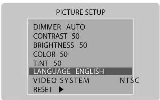
1) Press [MENU] button until OSD menu [PICTURE SETUP] appears.
2) Press [▼ ▲ ] button to move to language and choose proper value by pressing [◀ ▶] button.
* Factory default setting is English (8 languages available).
5 INITIALIZATION
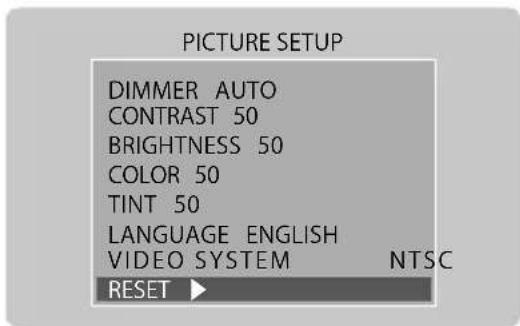
1) Press [MENU] button until OSD menu [PICTURE SETUP] appears.
2) Press [▼ ▲ ] button to move to RESET and then press [◀ ▶] button.
* Returns the Monitor to factory default settings except for video input (NTSC or PAL).
8. INSTALLATION
INSTALLATION (U-Bracket)
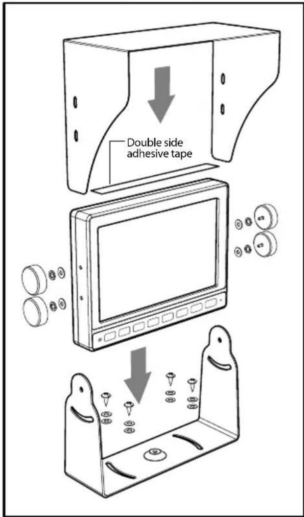
- Please ensure that the monitor is installed with enough room for heat to dissipate. Install the monitor stand with enclosed screws and double side adhesive tape as per the picture.
- Fix the monitor to the monitor stand firmly.
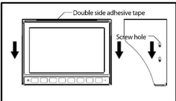
- Sun Visor should be installed with 4 screws.
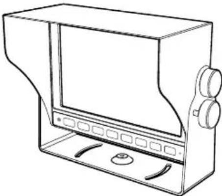
natural_image
Line drawing of a rectangular electronic device with control panel and buttons (no text or symbols)Standard Installation
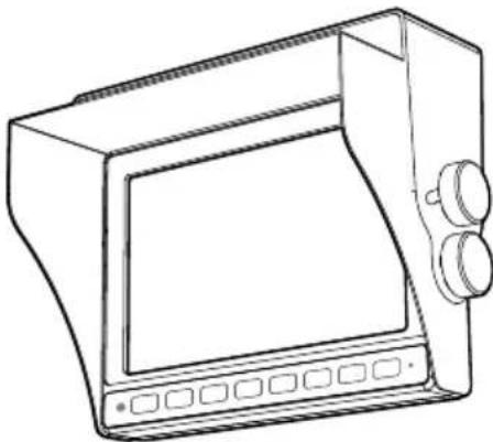
natural_image
Line drawing of a portable electronic device with front panel and control buttons (no text or symbols)Ceiling Installation
9. CONNECTIONS
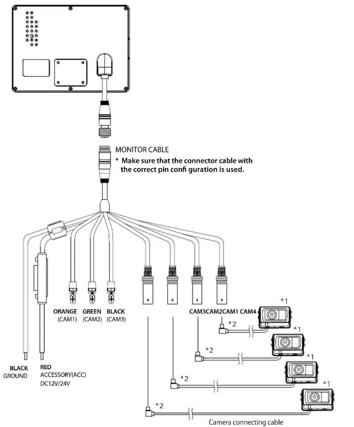
* 1 Use Clarion Cameras only.
* 2 A camera connecting cable, sold separately, is required for connecting the camera.
■ Please ensure that the correct trigger wires are connected to the corresponding cameras.
ORANGE (CAM1, priority)
Standby + (for rear-view)
GREEN, BLACK (CAM2, CAM3)
* Connect this cable to the "+" side of the Reverse gear globe.
Standby + (for side-view)
* Connect Green cable to the "+" side of the Left turn signal globe
- Connect Black cable to the "+" side of the Right turn signal globe.
10. TROUBLESHOOTING
| Problem | Cause | Measure |
| No image is displayed. | Is camera connected properly? | Check the wiring to the camera and the came connection. |
| Power does not turn on. | Is power cable connected properly? | Check the wiring. |
| Is a fuse blown out? | Replace with a fuse of the same amperage (5A) | |
| Color is washed-out. | Operating environment is inappropriate. | Temperature in the vehicle is below -10°C or over 60°C. Check to see that the temperature in the vehicle is appropriate (around 25°C). |
11. SPECIFICATIONS
| LCD panel | Screen size | 7 inch |
| Resolution | 800(W) x 3(RGB) x 480(H) | |
| Brightness | 400cd/m^2 | |
| Contrast ratio 500 : 1 | ||
| Power supply | Voltage | DC12V~24V (10.8V ~31.2V) |
| Current | Approx. 900mA ( DC12V, in case of connecting four sets of camera(CC-2000)).) | |
| Speaker | 0.5 Watt max. | |
| Language display selection | 8 Language | |
| Operating temperature | -10°C ~ +60°C / -14°F ~ +140°F | |
| Storage temperature | -20°C ~ +70°C / -4°F ~ +158°F | |
| Dimension (W x D x H) | 190 x 141 x 29mm/7.48 x 5.55 x 1.14 inch | |
| Weight 879g / 31oz (monitor only) | ||
* The design and specification are subject to change without notice.
Clarion Co., Ltd.
All Rights Reserved. Copyright © 2013: Clarion Co., Ltd.
Printed in Korea
2 0 1 3 / 1 2
- CJ-7500E
- CONTENTS
- ■Declaration of conformity
- Clarion Europe SAS
- SAFETY INSTRUCTIONS
- WARNING
- CAUTION
- BEFORE USE
- Precautions (when you use the monitor)
- Precautions (when you use the product in a vehicle)
- FEATURES
- CONTENTS
- BUTTON FUNCTIONS
- FUNCTIONS
- POWER ON/OFF
- VOLUME CONTROL
- ③ SCREEN SWITCH
- SELECT SPLIT MODE
- ⑤ CAMERA SELECTION
- 1) FULL SCREEN MODE
- 2) 2 SPLIT SCREEN MODE
- 3) TRIPLE SPLIT SCREEN MODE
- 4) QUAD SCREEN MODE
- CAMERA MIRROR/NORMAL MODE SETTING
- ON SCREEN DISTANCE MARKER SETTING
- 1) MARKER SELECTION
- 2) MARKER ADJUSTMENT (Adjusting the bumper position)
- ⑧ Automatic Screen switching using Trigger inputs
- SETTINGS
- VIDEO STANDARD SYSTEM NTSC/PAL SELECTION
- DIMMER SENSOR SETTING
- PICTURE SETUP
- LANGUAGE SETTING
- INITIALIZATION
- INSTALLATION
- CONNECTIONS
- TROUBLESHOOTING
- SPECIFICATIONS
- Clarion Co., Ltd.
Brand : CLARION
Model : CJ-7500E
Category : Dashboard camera