
GH-PCU31-VH - Computer Cooling Component GIGABYTE - Free user manual and instructions
Find the device manual for free GH-PCU31-VH GIGABYTE in PDF.


| Product Type | CPU Cooler |
| Compatible Sockets | Intel LGA775, LGA115x, LGA1366; AMD AM2, AM3, FM1, FM2 |
| Dimensions (L x W x H) | 120 mm x 80 mm x 150 mm |
| Weight | 520 g |
| Fan Speed | 900 – 2200 RPM (PWM controlled) |
| Noise Level | 18 – 32 dBA |
| Airflow | 45 – 85 CFM |
| Power Consumption | 3.6 W (fan only) |
| Heatsink Material | Aluminum fins with copper heat pipes |
| Bearing Type | Rifle bearing |
| Connector | 4-pin PWM |
| Main Functions | CPU cooling, heat dissipation, low noise operation |
| Maintenance & Cleaning | Dust removal with compressed air; avoid liquids |
| Safety | Use with proper thermal paste; do not obstruct fan |
| Spare Parts & Repairability | Fan replaceable; thermal paste not included |
| General Information | Compatible with most CPU sockets; includes mounting brackets |
Frequently Asked Questions - GH-PCU31-VH GIGABYTE
User questions about GH-PCU31-VH GIGABYTE
0 question about this device. Answer the ones you know or ask your own.
Ask a new question about this device
Download the instructions for your Computer Cooling Component in PDF format for free! Find your manual GH-PCU31-VH - GIGABYTE and take your electronic device back in hand. On this page are published all the documents necessary for the use of your device. GH-PCU31-VH by GIGABYTE.
USER MANUAL GH-PCU31-VH GIGABYTE
Installation Guide for
Intel Pentium 4, AMD Athlon XP, Athlon 64
GH-PCU31-VH
DATE:0223
Table of Content
Checklist 3
Specification 4
Feature 4

Installation Instructions for Intel Pentium 4 Clips 5
Installation Instructions for AMD Athlon XP Clip 6
Installation Instructions for AMD Athlon64 Clip 7
Power Installation and 3.5" Fan Speed Controller Installation 8
Power Installation and PCI Fan Speed Controller Installation 9
GH-PCU31-VH
-2-


Checklist
(2)GHPCU31-VH usersmanual
(3) HeatSink Paste (ShinEtsu X-23-7762)
(4) SpeedControl& 3.5"fontpanel
(5)PCI rear panel



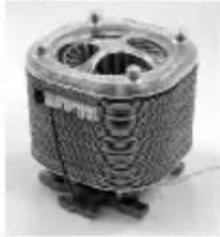
(1) GH-PCU31-VH Cooler
natural_image
Close-up of a coiled industrial fan or turbine component (no visible text or symbols)(6) Powercable


(7)P4Clips
(8)K7Clp
(9)K8Clip
(10)Screw

Before use, please remove the bottomprotective layer of the cooler.
Please make sure the computer is turned off and its power disconnected prior to installation.
GH-PCU31-VH

Specification
• HeatSink Dimension: 83 x 89 x 93mm
- RatedSpeed:2000\~4500rpm
- RatedVoltage:4\~12V
- Noise:192\~42.0dBA
- Bearing Type:2 Ball Bearing
Feature
- Unique patent for K8, K7 and P4 platform designs
• SmartIC controller fornoise and cooling - Top and bottom double airflow inlet central-blower
- Attractive LED lights display
• Multi-cooling of CPU and surrounding components - Heatpipedesign
- VR control function, suitable for both 3.5" front panel and PCI rear panel
• Tool-free and easy clip install
• Heatsink structure with enfirelycopper-based design
• Advancedheatsinkpaste included(ShinEtsu X-23-7762)
GH-PCU31-VH
-4-


Installation Instructions for Intel Pentium 4 Clips
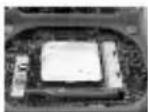
Figure 1

Figure 2
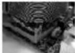

Figure 3
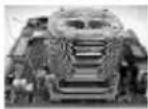

Figure 1
Please add an adequate layer of heatsink paste on the surface of the CPU.
Figure 2
Figure showing the correct installation of the cooler abp the CPU.
Figure 3
Hook the clip on one end of the cooler with the insert space at the CPU base (as seeing left Figure 3). Firmly push downwards to dip the cooler end in place. Do the same for the other clip of the cooler to secure cooler in place.
Figure 4
Connect the yellow 3-pin connector cable of the cooler to the CPU fan connector located on the motherboard.
Clips Installation is now complete.
Figure 4

Note: Please refer to page 8 & 9 for power installation and installation of the fan speed controller.
GH-PCU31-VH
Installation Instructions for AMD Athlon XP Clip


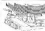

Figure 3
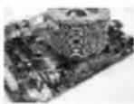

Figure 1

Figure 1
Please add an adequate layer of heat sink paste on the surface of the CPU. The picture on the right shows the three insert spaces on the cooler bracket where the CPU clips attach.
Attention!! The indication arrow on the cooler must align with the central CPU clip.
Figure 2
Place the cooler atop the CPU and insert the indication arrow side of the cooler in the space between the central jut of the CPU socket and the edge of the CPU.
Figure 3
Align the three spaces on the cooler with the three clips on the base of the CPU and then push firmly downwards to lock the cooler securely in place. A flat-head screwdriver can also be used to secure the clips in place. Figure 4
Connect the yellow 3-pin connector wire of the cooler to the CPU fan connector located on the motherboard.
Clip Installation is now complete.
Note: Please refer to page 8 & 9 for power installation
and installation of the fan speed controller.
-6-
GH-PCU31-VH
Installation Instructions for AMD Athlon 64 Clip


Figure 1


Figure 2


Figure 4
Figure 1
Please add an adequate layer of heat sink paste on the surface of the CPU.
Figure showing the correct in stallation of the cooler atop the CPU.
Align the three insert spaces of the clip with the three juts on the CPU socket and then push firmly downwards to hold the clip in space.
Push the lever on the side of the cooler towards the lever position on the base of the CPU to secure the cooler atop the CPU. Connect the yellow 3-pin connector cable of the cooler to the CPU fan connector located on the motherboard. Clip Installation is now complete.
Note: Please refer to page 8 & 9 for power installation and installation of the fan speed controller.
Figure 2
Figure 3
Figure 4
GH-PCU31-VH
Power Installation and 3.5" Fan Speed Controller Installation
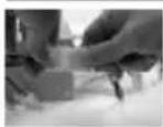
Figure 1
Figure 1
Connect the power cable of the power supply to the end of the 4-pin connector cable provided.


Figure 2
Figure 2
Connect the other end of the 4-pin connector cable to the PCB 4-pin connector on the coder.

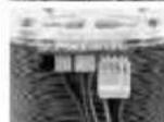
Figure 3
Figure 3
Securely hold the 3.5" fan speed controller bracket in place with the screws provided. Connect the 3-pin connector cable of the controller to the PCB 3-pin connector on the cooler.
Figure 4
Figure 4
Installation is complete.
GH-PCU31-VH
-8-
Power Installation and PCI Fan Speed Controller Installation


Figure 1
Disassemble the turn knob, bolt and fan speed controller from the 3.5" front panel and reassemble these parts onto a
Figure 1 PCIrearpanel in sequence.
Figure 2


Figure 2
Place the PCI rear panel with the fan speed controller in the selected PCI slot. Use screws to secure the PCI rear panel in place.
Figure 3
Connect the power cable of the power supply to the end of the 4-pin connector cable provided. Then connect the 3-pin power connector on the fan speed controller to the 3-pin connector on the cooler.

Figure 4
Figure 4
Installation is complete.
-9-
GH-PCU31-VH


- Table of Content
- Checklist
- Specification
- Feature
- Installation Instructions for Intel Pentium 4 Clips
- Installation Instructions for AMD Athlon XP Clip
- Installation Instructions for AMD Athlon 64 Clip
- Power Installation and 3.5" Fan Speed Controller Installation
- Power Installation and PCI Fan Speed Controller Installation
Brand : GIGABYTE
Model : GH-PCU31-VH
Category : Computer Cooling Component