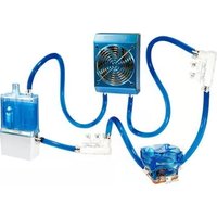
3D Galaxy II - Computer Cooling Component GIGABYTE - Free user manual and instructions
Find the device manual for free 3D Galaxy II GIGABYTE in PDF.


| Product Type | CPU Liquid Cooler |
| Brand | Gigabyte |
| Model | 3D Galaxy II |
| Compatible Socket | Intel LGA 775/115x/1366/2011, AMD AM2/AM3/FM1/FM2 |
| Radiator Dimensions | 120 x 120 x 25 mm |
| Fan Size | 120 x 120 x 25 mm |
| Fan Speed | 800 - 2000 RPM (PWM) |
| Fan Airflow | 74.5 CFM |
| Fan Noise Level | 18 - 35 dBA |
| Pump Speed | 2600 RPM |
| Pump Noise Level | < 25 dBA |
| Material | Copper base, aluminum radiator |
| Weight | 980 g |
| Power Consumption (Fan & Pump) | 12V, 0.3A (3.6W) |
| Coolant | Pre-filled, sealed system |
| Socket Compatibility | Intel LGA 775/115x/1366/2011, AMD AM2/AM3/FM1/FM2 |
| Installation | Easy push-pin or screw mounting for Intel/AMD |
| Maintenance | Dust cleaning on radiator/fan; no coolant refill needed |
| Safety | Avoid water ingress; use electrical precautions |
| Spare Parts | Replacement fans and mounting kits available |
| Warranty | 2 years limited |
Frequently Asked Questions - 3D Galaxy II GIGABYTE
User questions about 3D Galaxy II GIGABYTE
0 question about this device. Answer the ones you know or ask your own.
Ask a new question about this device
Download the instructions for your Computer Cooling Component in PDF format for free! Find your manual 3D Galaxy II - GIGABYTE and take your electronic device back in hand. On this page are published all the documents necessary for the use of your device. 3D Galaxy II by GIGABYTE.
USER MANUAL 3D Galaxy II GIGABYTE
- Before pouring liquid coolant into the tank to test the liquid cooling system, please reconfirm all the tubes have been fastened and the tube clips are in the right position.
- While the water in the tank is lower than the low water-level, the red light on the bottom of PCB will blink. (Please purchase GIGABYTE ™ liquid coolant to fill it.)
- When the liquid is lower than the low water-level, the system will turn off automatically within four seconds after detection of water inadequacy.
- While removing the tubes for disassembly, please make sure to keep all the devices away from any electronic part. (Please refer to disassembly process instruction)
The following are not covered by the warranty
- Use the product incorrectly or in a manner other than the designed purpose.
- Nonobservance of the proper operation provided. (e.g. over-clocking)
- Malfunction due to interference from other devices.
- Unauthorized modification of the product.
- Consequential damage to other objects due to the product's fault.
- Malfunction arising from casualties (earthquake, thunder, fire, and flood).
- The product's warranty label has been removed or damaged.
- The devices inside, including power supply, hard disk, CD-ROM drive, motherboard, ventilator, etc, are not detached from the casing prior to the transportation of the computer product, resulting in damage to the casing or computer-related devices.
- Any loss caused by failure to follow the installation process contained in the user manual.
- Any damage to the system arising from coolant leakage due to improper installation.
- Use only GIGABYTE ™ Liquid Coolant. Any damage arising from the use of liquids other than GIGABYTE ™ Liquid Coolant is not covered by the warranty.
Table content
1 Accessories List 4
2 Specification Instruction 6
3 Feature Instruction 6
4 Liquid Cooling System Installation 7
4-1 Installation Preparation 7
4-2 Intel ® Pentium ® 4 LAG775 Back Plate Installation 7
4-3 PCI Rear Fan Speed Controller Installation 8
4-4 Tube Installation 8
4-5 4-way Splitter Valve to the Tube on Waterblock Installation 9
4-6 Radiator to 4-way Splitter Valve Installation 10
4-7 Radiator to the Inlet of Water Tank 11
4-8 4-way Splitter Valve to the Outlet of Water Pump 11
4-9 Waterblock Installation 12
4-10 Intel ® Pentium ® 4 LGA775 Bracket Installation 12
4-11 AMD K8 Clip Installation 13
4-12 AMD AM2 Clip Installation 13
4-13 Fasten 4-way Splitter Valve 14
4-14 MOSFET Air Cooling Fan Installation 14
4-15 Pump Power Cord Installation 15
4-16 Fan Speed Control Box and Power Cord Instruction 16
4-17 Fan Speed Control Box Installation 16
4-18 Heat Sink Installation 17
5 Liquid Cooling System Installation and Test 18
5-1 Liquid Cooling System Installation and Test 18
5-2 Radiator Installation 19
6 Liquid Cooling System Disassembly 20
7 4-way Splitter Valve Instruction and User Manual 22
1. Accessories List
natural_image
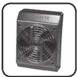
Exterior view of a gray server fan with visible ventilation grille (no text or symbols)(1) Radiator (2) Pump + Tank Assembly
natural_image
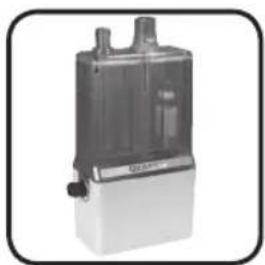
Exterior view of a mechanical device with no visible text or symbolsTank Assembly

natural_image
Close-up of a black plastic fan or compressor component (no visible text or symbols)(3) MOSFET Air Cooling Fan
natural_image
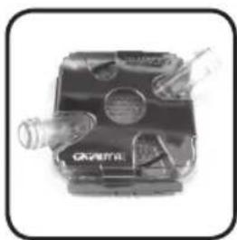
Close-up of a mechanical device with no visible text or symbols(4) Waterblock

natural_image
Close-up of a mechanical component with multiple cylindrical parts, labeled 'X2 pcs' (no other text or symbols visible)(5) 4 - way Splitter Valve
natural_image
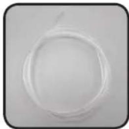
Circular white plastic film or wire on a plain background (no text or symbols)(6) 1 / 2 inch Tube (7) Tube Clips (8) Screws

natural_image
Two metallic cylindrical objects with a white plastic cap, labeled 'X8 pcs' at the bottom (no other text or symbols visible)
natural_image
Metal mechanical component with mounting holes and a central hole (no visible text or symbols)(11) Intel® Pentium® 4 LGA775 Bracket

natural_image
Close-up of four metallic screw fasteners (no text or symbols visible)
natural_image
Metallic mechanical component with a flanged end and central hub (no visible text or symbols)(12) AMD K8 / AM2 Clip

natural_image
Five screwdrivers arranged in a row, no text or symbols visible(9) Intel ® Pentium ® 4 LGA775 Spring Screws

natural_image
Close-up of a metallic X-shaped mechanical component with four arms and central square hole (no text or symbols)(10) Intel® Pentium® 4 LGA775 Back Plate

natural_image
Black-and-white photo of a mechanical device with circular components and a handle (no visible text or symbols)(15) PCI Rear Fan Speed Controller

natural_image
Metal bracket with a handle and mounting base, no visible text or symbols(16) Radiator Rack

natural_image
Close-up of a mechanical component with no visible text or symbols(13) AMD K8 / AM2 Bracket

natural_image
Black rectangular object with textured surface, possibly a tool or device (no visible text or symbols)(14) Fan Speed Control Box

natural_image
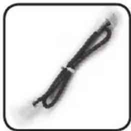
Close-up of a black cable with a looped end, isolated on white background (no text or symbols)(17)Pump Power Cord (18)Fan 1 to 2 Power Cord

natural_image
Two black cables with white connectors, no text or symbols visible3)Fan 1 to 2 Power Cord
natural_image
Close-up of a black cable with a loop, isolated on white background (no text or symbols)(19)Fan Speed Control Power Cord
natural_image
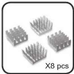
Four metallic heat sinks arranged in a row, labeled 'X8 pcs' below (no other text or symbols)(20) Heat Sink for Memory

natural_image
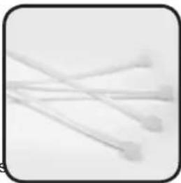
Two coiled spring-like objects, one labeled 'X2 pcs X' (no other text or symbols)(21)Bend Proof Spring (22)Nylon Tie (23)Grease (24)Gigabyte Liquid
natural_image
Close-up of three white hairpins with pointed tips, no text or symbols visible

natural_image
Close-up of a syringe with black liquid and white tip, no visible text or symbols

natural_image
Exterior view of a rectangular electronic device with a label (no visible text or symbols on the device body)Coolant

natural_image
Four black rectangular panels arranged in a curved pattern on a white background, labeled 'X2' at bottom (no other text or symbols)(25)Velcro (26)Quick Installation Guide

CAUTION
No.8 Screw: a – Secure PCI Rear Fan Speed Controller (1pc)
b – Secure Radiator ( 3pcs )
c - Pump + Tank Assembly (2pcs)
2. Specification Instruction
| Mosfet cooling fan | Fan size 80 x 80 x 25 mm | |
| Fan speed 2000 RPM | ||
| Fan Connector 3 pin | ||
| Bearing EBR | ||
| Noise 19 dBA | ||
| Pump | Dimensions 61 x 60 x 46 mm | |
| Maximum Capacity 400 L/hr | ||
| Noise 20 dBA | ||
| Bearing Ceramic Bearing | ||
| Life time 70000 hr (MTBF) | ||
| Radiator | Dimensions 125 x 197 x 64 mm | |
| Material Aluminum | ||
| Fan size 120 x 120 x 25 mm | ||
| Fan speed 1200 ~ 2600 RPM | ||
| Fan Connector 3 pin | ||
| Bearing 2 Ball | ||
| Noise 19~39 dBA | ||
| Tank | Dimensions 100 x 53 x 172 mm | |
| Capacity | 220cc. | |
| Valve | Dimensions | inlet:1/2"; outlet:1/4"*2,1/2"*1 |
| Materia | POM | |
| Tube | Dimension | 1/2 inch |
| Material | PVC, UV sensitive | |
| Coolant | Capacity | 600cc. |
| Color | Lite Blue | |
| Compatible CPU | Intel® Pentium® Extreme Edition Series | |
| Intel® Pentium® D Processor Series | ||
| Intel® Pentium® 4 Processor Series (LGA775) | ||
| Intel® CoreTM 2 Duo Processor Series | ||
| AMD AM2TM Series | ||
| AMD AthlonTM FX Series | ||
| AMD AthlonTM 64x2 Series | ||
| AMD AthlonTM 64 Series | ||
3.Feature Instruction
- Super huge copper base and unique water path design.
- Long-lived, quiet and powerful ceramic bearing pump.
- Auto-induction of low water-level (LWP) and over temperature (OTP) Protection.
-
Aluminum 4-way water path design radiator with 12 cm adjustable fan for lower noise.
-
Delicate sparkly blue LED light design tank; easy refilling coolant.
- Well-executed liquid cooling radiator fits most existed PC chassis.
- Multipurpose nanometer GIGABYTE TM coolant.
8.1/2inch UV soft tube; unique design to reduce bending needs. - Fully support cooling solution for the surrounding component of CPU (Mosfet).
- GIGABYTE ™ exclusive 4-way splitter valve design for faster replacement and add new cooling equipment.
11.PCI Rear Fan Speed Controller
12.Free heat sink for memory
13.Wide range use for AMD K8/AM2;Intel® Pentium® 4 LGA 775.
4. Liquid Cooling System Installation
Please follow the instruction.
4-1 Installation Preparation
Please make sure the power of PC has been turned off.
Tool needed: scissors, GIGABYTE TM coolant, grease, screwdriver.
4-2 Intel® Pentium® 4 LGA775 Back Plate Installation
(For AMD series CPU, please ignore this step)
4-2-1 Take off the double-side sticker on the Intel Pentium 4 LGA775 Back Plate (as Figure a), and stick it on the back of Intel Pentium 4 LGA775 CPU with aligning four holes on Intel Pentium 4 LGA775 Back Plate and four holes on the back of Intel Pentium 4 LAG775 CPU motherboard (as Figure b).

natural_image
Hand holding a small tool interacting with a metallic X-shaped mechanical component (no text or symbols visible)
natural_image
Close-up of a circuit board with a metallic X-shaped component (no visible text or symbols)Figure a Figure b
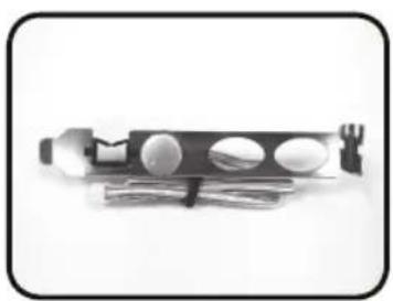
4-3 PCI Rear Fan Speed Controller Installation (as Figure a/b)
4-3-1 Place PCI rear fan speed controller to the back of the chassis (place on the lower PCI is recommended as Figure c.)
natural_image
Close-up of a mechanical device with circular components and a handle (no visible text or symbols)
natural_image
Close-up of hands assembling electronic components with visible circuitry and wiring (no text or symbols)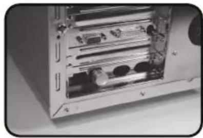
natural_image
Interior view of a computer drive bay showing internal components and ventilation slots (no visible text or labels)Figure a Figure b Figure c
4-4 Tube Installation
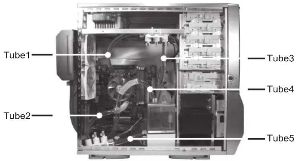
After measuring the distance between each parts of the cooling system, cut the tubes into five suitable sizes as it shows below. To get the right length for each tube, strongly recommend to fit all the components in the right position.
Liquid Cooling System complete installation diagram.
Tube3: The inlet of radiator
to 4-way splitter valve (1)

Tube4: The outlet of radiator to the inlet of the tank
Tube1: 4-way splitter valve (1) to the outlet of the waterblock
Tube2 : 4-way splitter valve (2) to the inlet of the waterblock
Tube5 : 4-way splitter valve(2) to the outlet of the tank

While placing tube, please do not bend the tube in order to avoid obstructing water flow (as the right Figure under). Besides, if needed, please use bend proof spring on the tube while bending it to avoid obstructing water flow efficiency.

natural_image
Close-up of a transparent cylindrical object with a circular symbol on the right (no text or labels visible)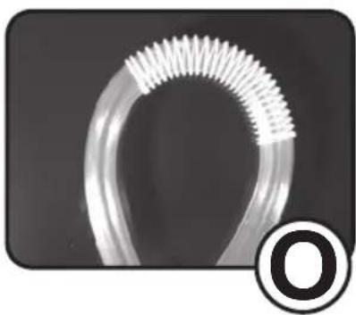
natural_image
Close-up of a transparent curved object with a white ribbed edge, labeled with a black circle containing the letter 'O' (no other text or symbols visible)
natural_image
Close-up of a transparent glass ring with a circular symbol containing an 'X' in the corner (no text or symbols on the ring itself)4-5 4-way Splitter Valve to the Tube on Waterblock Installation
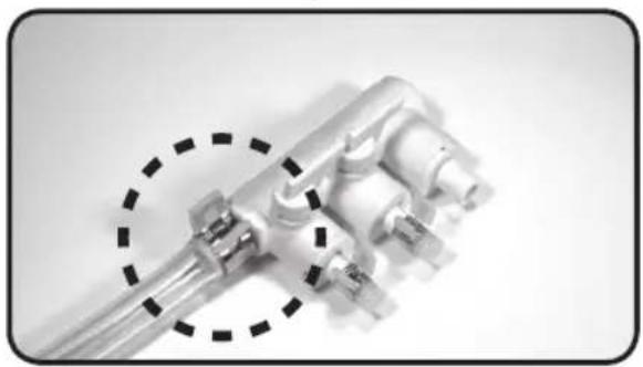
4-5-1 Connect one side of tube 1 to 4-way splitter valve (1) A as it shows in the picture and fasten the tube clip.
4-5-2 Connect the other side of tube 1 to the outlet of waterblock and fasten the tube clip.
natural_image
Close-up of a metallic mechanical component with multiple cylindrical ports and a dashed circular annotation (no text or symbols)
natural_image
Close-up of a glass vial with a dropper above it, partially covered by a metallic object and a coin for scale (no visible text or symbols)4-5-3 Connect one side of tube 2 to 4-way splitter valve (2) B as it shows in the figure and fasten the tube clip.
4-5-4 Connect the other side of tube 2 to the inlet of waterblock and fasten the tube clip.

natural_image
Close-up of mechanical components with a dashed circle highlighting a cluster of pins (no text or symbols visible)
natural_image
Close-up of a metallic tool interacting with a mechanical component (no visible text or symbols)
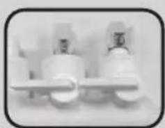
The 2 splitters in the middle of 4-way splitter valve can be used to support VGA, chipset liquid cooling system or other liquid cooling system.

If the 2 splitters in the middle of 4-way splitter valve are available, please do not take off the cap and switch them to horizontal to avoid leakage.
natural_image
Close-up of three white industrial pipe fittings with metal clamps, no visible text or symbols4-6 Radiator to 4-way Splitter Valve Installation
4-6-1 Thread Tube 3 through the hole on PCI slot (as Figure a) to connect one side of tube 3 to 4-way splitter valve (1) B and fasten the tube clips (as Figure b).

natural_image
Interior view of a computer tower case showing internal hardware racks and ventilation slots (no visible text or labels)
natural_image
Close-up of a mechanical or electrical component with metallic fittings and connectors (no visible text or symbols)
natural_image
Close-up of a metallic industrial fan or vent with two circular buttons and a side grille (no visible text or symbols)Figure a Figure b Figure c

For GIGABYTE™ 3D Aurora, Triton or Poseidon series user, the tube can be threaded through drainage inlet/outlet on the chassis. (as the two holes on the right in Figure c)
4-6-2 Connect the other side of tube 3 to the inlet of radiator and fasten the tube clips.

natural_image
Close-up of a mechanical component with a dashed circular annotation highlighting a specific area (no text or symbols visible)4-7 Radiator to the Inlet of Water Tank
4-7-1 Thread Tube 4 through the hole on PCI slot to connect one side of tube 4 to the outlet of radiator and fasten the tube clips.

natural_image
Close-up of a computer tower with visible internal components and a dashed circular outline (no text or symbols)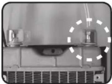
natural_image
Close-up of a mechanical component with a dashed circular annotation highlighting a specific area (no visible text or symbols)4-7-2 Connect the other side of tube 4 to the inlet of the tank and fasten the tube clips.

natural_image
Close-up of a mechanical component with a transparent cylindrical part and mounting base (no visible text or symbols)4-8 4-way Splitter Valve to the Outlet of Water Pump
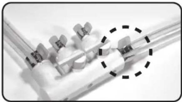
4-8-1 Connect one side of tube5 (as Figure shown) to 4-way splitter valve(2) and fasten the tube clips.
4-8-2 Connect the other side of tube5 to the outlet of the pump and fasten the tube clips.
natural_image
Close-up of a medical or laboratory device with multiple metallic components and a dashed circle highlighting a specific area (no visible text or symbols)
natural_image
Close-up of a laboratory glassware setup with a pipette and tubing (no visible text or symbols)4-9 Waterblock Installation

Please make sure to take off the "CAUTION" sticker and apply the grease on the CPU surface evenly.

Note: AMD K8 Bracket can be removed from waterblock (as Figure a) to adjust the appropriate installation direction. (as Figure b/c)

natural_image
Close-up of a square electronic component with a triangular warning symbol and mounting bracket (no readable text or symbols)
natural_image
Close-up of a hand holding a mechanical component with a circular hole and bolt holes (no visible text or symbols)
natural_image
Close-up of a computer motherboard with CPU socket and surrounding circuit board (no visible text or symbols)
natural_image
Two mechanical components with circular and rectangular features, one larger and one smaller, shown against a plain background (no text or symbols visible)
natural_image
Close-up of a mechanical component with arrows indicating direction (no visible text or symbols)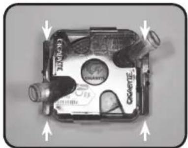
natural_image
Top-down view of a car body panel with visible branding and directional arrows (no readable text or symbols)Figure a Figure b Figure c
4-10 Intel® Pentium® 4 LGA775 Bracket Installation
4-10-1 Replace AMD K8 Bracket with Intel® Pentium® 4 LGA775 Bracket (accessory No. 11) (Figure a). Place the waterblock on the top of Intel® Pentium® 4 LGA775 CPU (Figure b) and adjust the appropriate installation direction (Figure c).

natural_image
Close-up of a metallic mechanical component with mounting holes and internal components (no visible text or symbols)
natural_image
Close-up of a computer motherboard with visible CPU socket and screwdriver (no text or symbols)
natural_image
Close-up of a computer motherboard with visible CPU socket and screwdriver (no text or symbols)Figure a Figure b Figure c
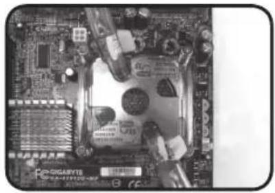
4-10-2 Secure Intel ® Pentium ® 4 LGA775 motherboard with attached spring screws.
natural_image
Close-up of a computer motherboard with visible CPU socket and surrounding components (no readable text or symbols)4-11 AMD K8 Clip Installation
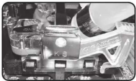
4-11-1 Align the AMD K8 Clip to three raised points on the CPU.

natural_image
Close-up of a computer motherboard with visible circuitry and components (no text or symbols)4-11-2 Push down the bar to surely secure.
natural_image
Close-up of a metallic electronic device with visible internal components and circuit board (no readable text or symbols)4-12 AMD AM2 Clip Installation
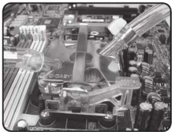
4-12-1 Align the AMD K8 clip to the raised point on the CPU.

natural_image
Close-up of a computer motherboard with visible CPU socket, RAM slots, and mechanical components (no readable text or symbols)4-12-2 Push down the bar to surely secure.
natural_image
Close-up of a computer motherboard with visible CPU socket and cooling pipes (no text or symbols)4-13 Fasten 4-way Splitter Valve
4-13-1 Using the nylon tie to fasten 4-way splitter valve on trestle of the chassis. If there is no trestle available, try to find an applicable place to fasten it.

natural_image
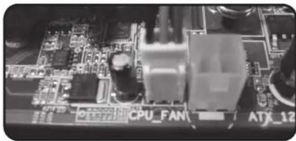
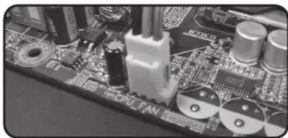
Close-up of a mechanical assembly with two white plastic components mounted on a metal frame, no visible text or symbols.4-14-2 Plug the power cord of MOSFET air cooling fan to the socket on motherboard CPU fan.
natural_image
Close-up of a computer motherboard with visible CPU fan and ATX_12 labels (no readable text beyond labels)a :3-pin CPU fan socket
natural_image
Close-up of a computer motherboard with visible components and circuit board (no readable text or symbols)b: 4-pin CPU fan socket (Intel® Pentium® 4 LGA775)
4-14 MOSFET Air Cooling Fan Installation
4-14-1 Place MOSFET air cooling fan on the top of waterblock and make sure that four feet of the air cooling fan are secured on waterblock.

natural_image
Close-up of a mechanical piston assembly with dashed circular annotation (no visible text or symbols)
natural_image
Close-up of a mechanical component with a dashed circular outline highlighting a section (no visible text or symbols)4-14-3 Plug the power cord of MOSFET air cooling fan into fan 1 to 2 power cord.

natural_image
Close-up of a computer motherboard with visible CPU socket and connector wires (no text or symbols)4-15 Pump Power Cord Installation
4-15-1 Prepare Pump Power Cord a : 6-pin connector b : female 2-pin connector c : male 2-pin connector d : 4-pin connector

natural_image
Close-up of a black electrical plug with wires, labeled A, B, C, D (no text or symbols on the plug itself)4-15-2 Connect the Power SW (female 2-pin connector) from the chassis's panel with the pump power cord male 2-pin connector
a: Power SW (female 2-pin connector) from the chassis's panel
b: Pump power cord male 2-pin connector

4-15-3 Connect the pump power SW cord female 2-pin connector with “+ P W -” jumper on the motherboard.

natural_image
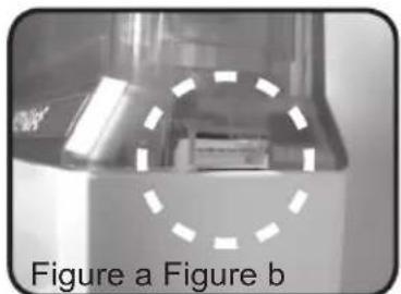
Close-up of a mechanical or electronic component with no visible text or symbols4-15-4 Connect the pump power cord 6-pin connector with the back of the tank, (as Figure a /b)
natural_image
Close-up of a mechanical component with dashed circular annotation highlighting a feature, labeled Figure a (Figure b)
natural_image
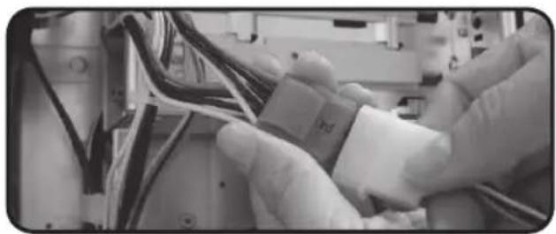
Close-up of a mechanical component with a dashed circular outline highlighting a section (no visible text or symbols)4-15-5 Connect 4-pin power supply connector with the 4-pin pump cord connector.
natural_image
Close-up of gloved hands assembling electronic components with wires (no visible text or symbols)4-16 Fan Speed Control Box and Power Cord Instruction

4-17 Fan Speed Control Box Installation
Tool needed: Fan Speed Control Box, Fan Speed Control Box Connect Line.
4-17-1 Thread the radiator fan connector through the hole of PCI rear fan speed controller.
4-17-2 Plug the connector from the PCI rear fan speed controller into the fan speed control box.

natural_image
Close-up of a mechanical component with a dashed circle highlighting a section, showing internal wiring and components (no visible text or symbols)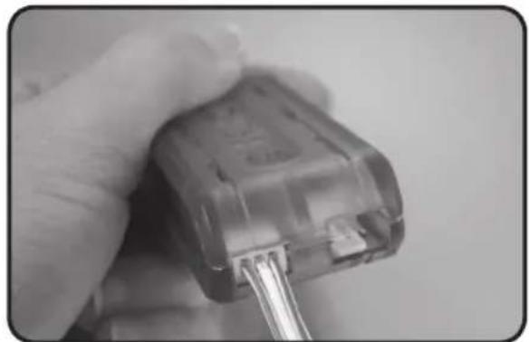
natural_image
Close-up of a hand holding a small electrical plug with a metal screwdriver inserted (no visible text or symbols)4-17-3 Plug the radiator fan power cord into the fan speed control box.

natural_image
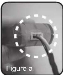
Close-up of a hand holding a transparent electrical plug with wires inserted (no visible text or symbols)4-17-4 To accomplish installation, plug the power cord of fan speed control box into the connector on the fan speed control box (as Figure a) and plug the other side of the power cord into the available 1 to 2 socket (as Figure b).
natural_image
Close-up of a hand holding a cylindrical electronic component with a wire, labeled 'Figure a' (no other text or symbols visible)
natural_image
Close-up of electrical wires and components with no visible text or symbols4-18 Heat Sink Installation
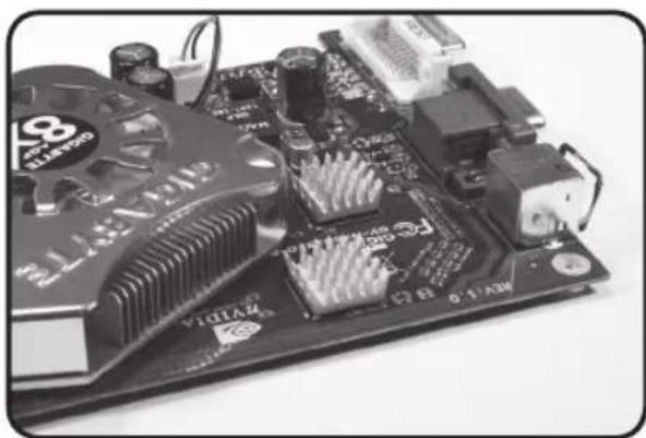
4-18-1 Heat sink( 8 pcs) can be pasted on the small chips on the motherboard or VGA card to lower the temperature.
natural_image
Close-up of a computer motherboard with visible components and no readable text or symbols
natural_image
Close-up of a computer motherboard with visible circuitry and components (no readable text or symbols)5. Liquid Cooling System Installation and Test
Before pouring liquid coolant into the tank to test the liquid cooling system, please remove the tank from the chassis to avoid damaging other components.
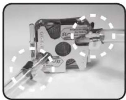
Before turning on the power, please confirm that all the tube clips are fastened; leakage of liquid coolant due to improper installation may damage the system that is not covered by warranty. (as figure shown)
natural_image
Close-up of a mechanical component with metallic parts and a circular feature, no visible text or symbols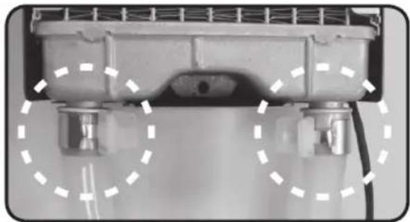
natural_image
Close-up of a mechanical component with dashed circular annotations highlighting features (no visible text or symbols)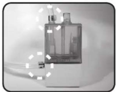
natural_image
Black-and-white photo of a laboratory flask with a transparent chamber and a side arm, no visible text or symbols.
natural_image
Close-up of white industrial piping fittings and valves on a shelf (no visible text or symbols)
Use only GIGABYTE TM liquid coolant; any damage arising from using other liquid product is not covered by warranty.
5-1 Liquid Cooling System Installation and Test
Tool needed: Coolant
5-1-1 Open the lid of the tank to pour in liquid coolant and close the lid.

natural_image
Close-up of a hand holding a computer monitor next to a CPU socket (no visible text or symbols)5-1-2 Turn on the power until all liquid coolant drains into the tubes; the red light on the bottom of the PCB will blink and bleep; the system will turn off automatically within 4 seconds. (This is normal or initial refilling of liquid coolant since the tube and radiator are not full of liquid.)
5-1-3 Open the lid of the tank again to refill the tank with liquid coolant and than close the lid. Turn on the power one more time and repeat this step until the water is no longer lower than the low water-level.

natural_image
Black-and-white photo of a server rack unit with visible cables and hardware, no text or symbols present.
natural_image
Close-up of a computer monitor with cables and a cable connector, no visible text or symbols
Note: For the first time of pouring liquid coolant into the tank; the radiator should be lay down flat to facilitate exhaust air to ensure the liquid cooling system to function silently. Installing the radiator in accordance with the following step 5-2 ; make sure all the air bubble in the tube has been removed to ensure the performance of cooling.

Be aware of abnormal leakage. If the installation was correct and the tube clips are fastened, and the liquid cooling system leaks, please turn off the power immediately and drain out all coolant. Contact GIGABYTE™ dealers or GIGABYTE™ service center.
5-2 Radiator Installation
5-2-1 Lock the radiator rack to the radiator with screws.

natural_image
Close-up of a metallic heat exchanger with a handle and grid-patterned insulation (no text or symbols visible)5-2-2 Remove the 2 screws on the power supply at the rear of chassis as shown.
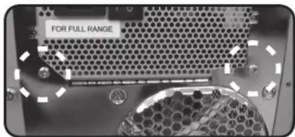
5-2-3 To accomplish liquid cooling system, align the 2 screw holes on the radiator rack to the 2 screw holes on the power supply and fasten them up.


With GIGABYTE™ 3D Aurora, Triton, Poseidon series, water tank can be placed inside of the chassis. [use 2 screws (b), please refer to accessories list]
Velcro could be used to place the tank while using the chassis other than 3D Aurora, Triton and Poseidon series.

natural_image
Close-up of a hand holding a white rectangular electronic component with four vertical slots (no visible text or symbols)
natural_image
Front view of a white electronic device with two slots and two buttons, no visible text or symbols6. Liquid Cooling System Disassembly
Tool needed: Pail, screwdriver
Preparation: Please place the chassis on a table and a pail on the floor.

While removing the tubes for disassembly, please make sure to keep all the devices away from any electronic part.
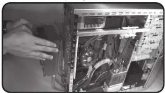
6-1-1 Remove radiator from the rear of the chassis and lay it on the table.
(Caution: Do not remove the tube at this point)
6-1-2 Remove MOSFET air cooling fan from the waterblock.
natural_image
Close-up of a hand installing or adjusting an internal computer tower case with visible circuitry and hardware (no text or symbols)
natural_image
Close-up of a hand inserting a flexible cable into a computer motherboard (no visible text or symbols)6-1-3 Release the clip of waterblock from CPU.
(Caution: Do not remove the tube at this point)

natural_image
Close-up of hands working on a computer motherboard with CPU socket and CPU socket (no visible text or symbols)6-1-5 Remove pump + tank and 4-way splitter valve from the chassis; and set a pail on a lower position to fill the coming out coolant.

natural_image
Close-up of a computer setup with CPU, RAM, and connected tubing (no visible text or symbols)6-1-7 Remove the tube; let the water from waterblock and the tube drift into the pail.

natural_image
Close-up of hands pouring liquid into a container with a tool (no visible text or symbols)6-1-4 Cut and remove the nylon tie which is used to fasten 4-way splitter valve.
natural_image
Close-up of a hand adjusting a USB cable inside an electronic device (no visible text or symbols)6-1-6 Release the tube clip on the inlet of the waterblock; and place the waterblock on the top of the pail.

natural_image
Close-up of a robotic arm connecting a mechanical component to a device labeled 'GIGABYTE' (no readable text or symbols on the device itself)6-1-8 Release the tube clip on the inlet of the tank and make sure if all the coolant drifts out from the tube. Remove the tube, tube clip and spring.

natural_image
Close-up of a hand inserting a plastic component into a computer motherboard (no visible text or symbols)6-1-9 Remove tube from PCI slot and be careful to avoid the leakage. Let the coolant drift into the pail. For the tube on the other side of radiator, please repeat this step until all the coolant drifts out.

natural_image
Close-up of hands installing a cable with a computer tower panel (no visible text or symbols)7. 4-way Splitter Valve Instruction and User Manual Adding
VGA waterblock and chipset waterblock without disassembly)

Ex. GIGABYTE™ blue eye and chipset waterblock

Please make sure to turn off PC power before installation.
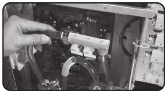
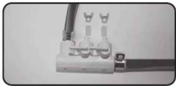
7-1 Remove the caps and tube clips from 4-way splitter valve.

Do not switch on at this point.
natural_image
Close-up of a white electrical plug with two connectors and a cable (no visible text or symbols)7-2 Cut a tube into suitable size; connect one side of the tube with the first splitter on 4-way splitter valve(1) and connect the other side with the inlet of VGA Blue Eye and fasten the tube clips.
7-3 Cut a tube into suitable size; connect one side of the tube with the second splitter on 4-way splitter valve(2) and connect the other side with the outlet of VGA Blue Eye and fasten the tube clips.

natural_image
Close-up of a cable connector with wires and connectors (no visible text or symbols)
natural_image
Close-up of a computer motherboard with a highlighted CLEARTI chip and cable (no readable text or symbols)
natural_image
Close-up of electrical connectors with wires and connectors (no visible text or symbols)
natural_image
Close-up of an electronic circuit board with visible components and traces (no readable text or symbols)7-4 Cut a tube into suitable size; connect one side of the tube with the second splitter on 4-way splitter valve(1) and connect the other side with the outlet of chipset waterblock and fasten the tube clips.

natural_image
Close-up of electrical connectors with wires and components (no visible text or symbols)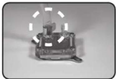
natural_image
Close-up of a mechanical device with a transparent housing and a curved arrow indicating rotation (no visible text or symbols)7-5 Cut a tube into suitable size; connect one side of the tube with the first splitter on 4-way splitter valve(2) and connect the other side with the inlet of chipset waterblock and fasten the tube clips.

natural_image
Close-up of a white electrical terminal with three leads and wires (no visible text or symbols)
natural_image
Exterior view of a mechanical device with no visible text or symbols7-6 Before turning on the power, please make sure all tube clips are fastened (as shown on Figure a, Figure b and Figure c) and switch on the 4-way splitter valve.

natural_image
Close-up of a circuit board component with visible traces and connectors (no text or symbols)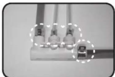
natural_image
Close-up of three connected electrical connectors with wires, no visible text or symbols
natural_image
Close-up of a mechanical component with circular cutouts, labeled 'Figure c Figure d' (no other text or symbols visible)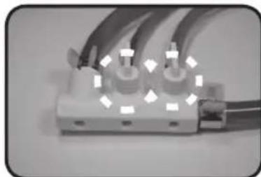
natural_image
Close-up of a white electrical connector with multiple wires and connectors (no visible text or symbols)7-7 To accomplish liquid cooling system, after turning on the power, appropriately pour coolant into the tank.

CAUTION
While removing the tubes for disassembly, please make sure to switch off 4-way splitter valve, turn off the power and keep all the devices away from any electronic part.


- The following are not covered by the warranty
- Table content
- Accessories List
- Specification Instruction
- 3.Feature Instruction
- Liquid Cooling System Installation
- 4-1 Installation Preparation
- 4-2 Intel® Pentium® 4 LGA775 Back Plate Installation
- (For AMD series CPU, please ignore this step)
- 4-3 PCI Rear Fan Speed Controller Installation (as Figure a/b)
- 4-4 Tube Installation
- 4-5 4-way Splitter Valve to the Tube on Waterblock Installation
- 4-6 Radiator to 4-way Splitter Valve Installation
- 4-7 Radiator to the Inlet of Water Tank
- 4-8 4-way Splitter Valve to the Outlet of Water Pump
- 4-9 Waterblock Installation
- 4-10 Intel® Pentium® 4 LGA775 Bracket Installation
- 4-11 AMD K8 Clip Installation
- 4-12 AMD AM2 Clip Installation
- 4-13 Fasten 4-way Splitter Valve
- 4-14 MOSFET Air Cooling Fan Installation
- 4-15 Pump Power Cord Installation
- 4-16 Fan Speed Control Box and Power Cord Instruction
- 4-17 Fan Speed Control Box Installation
- 4-18 Heat Sink Installation
- Liquid Cooling System Installation and Test
- 5-1 Liquid Cooling System Installation and Test
- 5-2 Radiator Installation
- Liquid Cooling System Disassembly
- 4-way Splitter Valve Instruction and User Manual Adding
Brand : GIGABYTE
Model : 3D Galaxy II
Category : Computer Cooling Component