
AWR-654GR - Router Advantek Networks - Free user manual and instructions
Find the device manual for free AWR-654GR Advantek Networks in PDF.


| Product Type | Wireless Broadband Router |
| Model | AWR-654GR |
| Wireless Standard | IEEE 802.11g (up to 54 Mbps), backward compatible with 802.11b |
| Ports | 4 x 10/100 Mbps LAN (Auto MDI/MDIX), 1 x 10/100 Mbps WAN |
| Power Supply | DC 12V, 1A external adapter (included) |
| Security | WEP 64/128-bit, WPA-PSK, WPA (TKIP/AES), WPA2 (TKIP/AES), WPS, MAC address filtering, SPI firewall, URL filter |
| Network Features | NAT, DHCP server, static routing, port triggering, virtual server, DMZ, DDNS, VPN passthrough (IPsec, PPTP, L2TP) |
| Wireless Features | SSID broadcast enable/disable, wireless MAC filter, WPS (PIN/PBC), radio on/off scheduling |
| Management | Web-based GUI (HTTP), remote management, firmware upgrade, backup/restore settings |
| LED Indicators | Power, WLAN, WAN, LAN (1-4) |
| Antenna | Internal (fixed) |
| Weight | Approx. 200 g (estimated) |
| Dimensions (L x W x H) | Approx. 150 x 110 x 30 mm (estimated) |
| Operating Temperature | 0°C to 40°C (32°F to 104°F) |
| Storage Temperature | -20°C to 60°C (-4°F to 140°F) |
| Maintenance | Keep away from metal obstructions, direct sunlight, and sources of interference; use only supplied power adapter. |
| Safety | FCC Class B, CE Mark; maintain 20 cm distance from body for RF exposure. |
Frequently Asked Questions - AWR-654GR Advantek Networks
User questions about AWR-654GR Advantek Networks
0 question about this device. Answer the ones you know or ask your own.
Ask a new question about this device
Download the instructions for your Router in PDF format for free! Find your manual AWR-654GR - Advantek Networks and take your electronic device back in hand. On this page are published all the documents necessary for the use of your device. AWR-654GR by Advantek Networks.
USER MANUAL AWR-654GR Advantek Networks
Advantek Networks
Wireless – G Broadband Router
Users Manual
Model# AWR-654GR
FCC Warning
This equipment has been tested and found to comply with the limits for a Class C digital device,
pursuant to part 15 of the FCC Rules. These limits are designed to provide reasonable protection against harmful interference in a residential installation. This equipment generates, uses, and can radiate radio frequency energy and, if not installed and used in accordance with the instructions, may cause harmful interference to radio communication. However, there is no guarantee that interference will not occur in a particular installation. If this equipment does cause harmful interference to radio or television reception, which can be determined by turning the equipment off and on, the user is encouraged to try to correct the interference by one or more of the following measures:
- Reorient or relocate the receiving antenna.
- Increase the separation between the equipment and receiver.
- Connect the equipment into an outlet on a circuit different from that to which
- Consult the dealer or an experienced radio/TV technician for help. the receiver is connected.
FCC Caution: Any changes or modifications not expressly approved by the party responsible for compliance could void the user's authority to operate this equipment.
This device complies with Part 15 of the FCC Rules. Operation is subject to the following two conditions: (1) This device may not cause harmful interference, and (2) this device must accept any interference received, including interference that may cause undesired operation.
NOTE: All Telecom and safety Tests only include this content hardware device only.
IMPORTANT NOTE:
FCC Radiation Exposure Statement:
This equipment complies with FCC radiation exposure limits set forth for an uncontrolled environment. This equipment should be installed and operated with a minimum distance of about eight inches (20cm) between the radiator and your body.
This transmitter must not be co-located or operated in conjunction with any other antenna or transmitter.
Modular Approval Statement:
This device is intended to be used only for OEM integrator under the following conditions:
1) The antenna must be installed such that 20 cm is maintained between the antenna and users, and
2) The transmitter module may not be co-located with any other transmitter or antenna.
IMPORTANT NOTE:
In the event that these conditions cannot be met (for example certain laptop configurations or co-location with another transmitter), then the FCC authorization is no longer considered valid and the FCC ID cannot be used on the final product. In these circumstances, the OEM integrator will be responsible for re-evaluating the end product (including the transmitter) and obtaining a separate FCC authorization.
CE Mark Warning
This is a Class B product. In a domestic environment, this product may cause radio interference, in which case the user may be required to take adequate measures.
Copyright
2009 All Rights Reserved.
No part of this document can be copied or reproduced in any form without written consent from the company.
Trademarks:
All trade names and trademarks are the properties of their respective companies.
Table of Contents
1. Introduction......5
1.1 Features....5
1.2 Package Contents ....7
1.3 LEDs Indication & Connectors of Wireless Router ....7
1.4 System Requirements......8
1.5 Before you proceed....8
2. Setting up the hardware....9
2.1 Setting up a wired connection....9
2.2 Setting up a wireless connection....9
3. Configuring the network client....9
3.1 Windows 9x/ME ....10
3.2 Windows NT4.0....11
3.3 Windows 2000....13
3.4 Windows XP....14
3.5 Windows Vista ....15
4. Configuring via the web GUI ....17
4.1 To configure via the web GUI ....17
4.2 Wireless....18
4.2.1 General....18
4.2.2 WPS....19
4.2.3 Wireless MAC Filter....20
4.2.4 Professional....20
4.3 LAN 21
4.3.1 LAN IP 22
4.3.2 DHCP Server 22
4.3.3 Route....24
4.4 WAN....25
4.4.1 Internet Connection ....25
4.4.2 Port Trigger....27
4.4.3 Virtual Server....27
4.4.4 DMZ 28
4.4.5 DDNS....29
4.5 Firewall ....30
4.5.1 General....30
4.5.2 URL Filter....31
4.5.3 MAC Filter 32
4.5.4 LAN to WAN Filter 32
4.6 Administration....34
4.6.1 Status ....34
4.6.2 System ....35
4.6.3 Firmware Upgrade....36
4.6.4 Restore/Save/Upload Setting 36
4.7 System Log ....38
4.7.1 General Log ....38
4.7.2 System Status ....39
4.7.3 DHCP Leases....39
4.7.4 Wireless Log....40
4.7.5 Routing Table 40
1. Introduction
Thank you for purchasing the Wireless 11g Access Point (AP) Router. This Wireless AP Router, IEEE 802.11g standard compliant, is a high quality and reliable Internet routing and security device, enables multiple users to share the Broadband Internet connection with or without wires through a Cable or DSL modem. Simply install the router, connect to Cable/DSL modem, and surf Internet without extra efforts. Acting as a 10/100Mbps 4-port Ethernet switch as well, the router, with all ports supporting MDI/MDIX, allows you to use CAT5 cable to uplink to other routers/switches.
The Wireless 11g AP Router is featured with advanced security technology, supporting WEP, WPA-PSK, WPA (Wi-Fi Protected Access) TKIP/AES, WPA2 and WPS. With the router, your network is armed with the highest levels of protection. The Router provides a total solution for the Small and Medium-sized Business (SMB) and the Small Office/Home Office (SOHO) markets, giving you an instant network today, and the flexibility to handle tomorrow's expansion and speed.
![graph TD A["Internet"] --> B["ADSL or Cable Modem"] B --> C["Laptop With Ethernet"] C --> D["Desktop PC With Ethernet"] D --> E["Wireless Broadband Router"] E --> F["Wireless Users"] E --> G["Computer"]](/content/2026/05/920896/images/979dd1a249ef3e1f6c9416a238f477d5ef9f553fda139bdfeec9a5aaf20a2bbb.jpg)
1.1 Features
Internet Access Features
- Shared Internet Access: All users on the LAN or WLAN can access the Internet through the Wireless Router, using only a single external IP address. The local (invalid) IP addresses are hidden from external sources. This process is called NAT (Network Address Translation).
- DSL and cable modem Support: The Wireless Router has a 10/100BaseT Ethernet WAN port for connecting a DSL or cable modem. All popular DSL and cable modems are supported.
- PPPoE and PPTP Support: The Internet (WAN port) connection supports PPPoE (PPP over Ethernet) and PPTP (Point-to-Point Tunneling Protocol), as well as "Direct Connection" type services.
- Fixed or Dynamic IP Address: On the Internet (WAN port) connection, the Wireless Router supports both Dynamic IP address (IP address is allocated on connection) and Fixed IP address.
Advanced Internet Functions
- Conferencing & Telephony Applications: Internet Telephony and Conferencing applications are supported.
- DMZ: One PC on your local LAN can be configured to allow unrestricted 2-way communication with Servers or individual users on the Internet.
- URL Filter: Use the URL Filter to block access to undesirable Web sites by LAN users, or Wireless LAN users.
Wireless Features
• Compliant with IEEE 802.11g standard.
• Up to 54Mbps data transfer rates (wireless)
• Backward compatible with IEEE802.11b (at 11Mbps)
• WEP Support: Support 64/128 bit WEP (Wired Equivalent Privacy) encryption.
• WPA Support: Support WPA-PSK Pass Phrase, and WPA TKIP/AES Data Encryption.
• WPA2 Support: Support WPA2 TKIP/AES.
WPS Support
- Access Control: This feature ensures that only access Wireless Stations that can access your LAN.
• Simple Configuration: All default settings can be changed easily.
LAN Features
• 4-Port Ethernet switch : The Wireless Router provides 4 10/100BaseT switching ports
- DHCP Server Support: This feature provides a dynamic IP address to PCs and other devices upon request. The Wireless Router can act as a DHCP Server for devices on your local LAN and WLAN.
Configuration and Management
- Easy Setup: Users allow to configure Wireless Router from anywhere on the LAN or WLAN via WEB browser.
- Remote Management: The Wireless Router can be managed from any PC on the LAN.
- UPnP Support: Universal Plug and Play feature. UPnP is supported by Windows ME or later.
Security Features
- Password Protected Configuration: Optional password protection is provided to prevent unauthorized users from modifying the configuration data and settings.
-
Wireless LAN Security: Supports 64/128 bit WEP Encryption, WPA-PSK, WPA TKIP/AES, WPA2 TKIP/AES, and WPS.
-
NAT Protection: This feature allows all LAN users to share a single IP address and all users' IPs are hidden. From the external viewpoint, there is no network only Wireless Router exists.
- Firewall: All incoming data packets are monitored and all incoming server requests are filtered.
1.2 Package Contents
• One Wireless 11g AP Router
• One External Power Adapter
• One CD including user's manual
• One RJ-45 Ethernet Cable
1.3 LEDs Indication & Connectors of Wireless Router
Front Panel LEDs Indication

| LED | Light | Status | Description |
 PWR PWR | OnOff | Wireless Router is powered on.No power. | |
 WLAN WLAN | Slow BlinkingBlinking | WLAN is successfully connected.Data is being sent or received. | |
 WAN WAN | OnBlinking | WAN port is successfully connected.Data is being sent or received. | |
 LAN(1, 2, 3, 4) LAN(1, 2, 3, 4) | OnBlinking | LAN port is successfully connected.Data is being sent or received. |
Back Panel Connectors

| Button/port | Description |
| DC IN Connect with DC Power Adapter. | |
| Reset Reset configurations to default. Press the button and hold for 10 seconds. | |
| WPS Click WPS button about 2-3 seconds while you are connecting a PC of wireless adapter with WPS function (you must enable WPS' PBC function). | |
| LAN(1x, 2x, 3x, 4x) | Connect LAN systems with RJ-45 cable. |
| WAN Connect DSL or Cable modem. | |
1.4 System Requirements
Before installing the Wireless Router, ensure that your system/network meets he following requirements:
• One or more PCs (desktop or notebook) with Ethernet interface.
• TCP/IP protocol must be installed on all PCs.
• Have valid Internet Access account and a DSL or cable modem.
• 10Base-T/100Base-TX network cables with RJ-45 connectors.
- In case to use Wireless Access Point, all Wireless devices must be compliant with IEEE 802.11b/g.
• System with MS Internet Explorer ver. 6.0 or later version
1.5 Before you proceed
Take note of the following guidelines before installing the Wireless Router:
- The length of the Ethernet cable that connects the device to the network (hub, ADSL/cable modem, router, wall patch) must not exceed 100 meters.
- Place the device on a flat, stable surface as far from the ground as possible.
- Keep the device clear from metal obstructions and away from direct sunlight.
- Keep the device away from transformers, heavy-duty motors, fluorescent lights, microwave ovens, refrigerators, and other industrial equipment to prevent signal loss.
• Install the device in a central area to provide ideal coverage for all wireless mobile devices.
2. Setting up the hardware
2.1 Setting up a wired connection
Wireless Router is supplied with an Ethernet cable in the package. The wireless router has integrated auto-crossover function, so use either straight-through or crossover cable for wired connection
1) Power off Wireless Router and DSL/cable modem.
2) Connect systems to the LAN ports on the Wireless Router with straight LAN cables.
3) Connect the DSL or cable modem to the WAN port on the Wireless Router.
4) Power on DSL or cable modem first, then connect power adapter to the power jack on the Wireless Router and plug the power cable into an outlet.
5) Check LEDs.
a) Once power on Wireless Router, Power LED should be on.
b) LAN LED should be on for each active LAN connection.
c) The WAN LED should be on when the DSL or cable modem is connected.
Warning: Only use the power adapter is provided from this package, use other power adapter may cause hardware damage.
2.2 Setting up a wireless connection
1) Turn on your router and the modem.
2) Using an Ethernet cable, connect the modem to the router's WAN port.
3) Connect an IEEE 802.11b/g compatible WLAN card. Refer to your wireless adapter user manual for wireless connection procedures. By default, the SSID of the Wireless Router is "default" (in lower case), encryption is disabled and open system authentication is used.
3. Configuring the network client
To access the Wireless Router, you must have the correct TCP/IP settings on your wired or wireless clients. Ensure that the clients' IP addresses are within the same subnet as the Wireless Router.
By default, the Wireless Router integrates the DHCP server functions, which automatically assign IP addresses to the clients in your network.
But in some instances, you may want to manually assign static IP addresses on some of the clients or computers in your network rather than automatically getting IP addresses from your wireless router.
Follow the instructions below that correspond to the operating system installed on your client or computer.
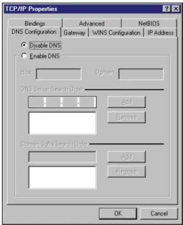
3.1 Windows 9x/ME
- Click Start > Control Panel > Network to display the Network setup window.
- Select TCP/IP then click Properties.

- If you want your computer to automatically obtain an IP address, click Obtain an IP address automatically then click OK. Otherwise, click Specify an IP address, then key in the IP address and Subnet Mask.

- Select Gateway tab, and key in New gateway then click Add.

- Select the DNS configuration tab and click Enable DNS. Key in Host, Domain, and DNS Server Search Order, then click Add.
- Click OK.
3.2 Windows NT4.0
- Go to Control Panel > Network to display the Network setup window then select the
Protocols tab.
- Select TCP/IP Protocol from the Network Protocols list then click Properties.

-
From the IP Address tab of the Microsoft TCP/IP Properties windows, you can:
-
Select the type of network adapter installed in your system.
- Set the router to assign IP address automatically.
- Manually set up the IP address, subnet mask, and default gateway.

- Select DNS tab then click Add under the DNS Service Search Order and key in DNS.

3.3 Windows 2000
- Click Start > Control Panel > Network and Dial-up Connection. Right-click Local Area Connection, then click Properties.
![Local Area Connection Properties General Connect using: SIS 900-Based PCI Fast Ethernet Adapter Configure Components checked are used by this connection: ✓ Client for Microsoft Networks ✓ File and Printer Sharing for Microsoft Networks ✓ Internet Protocol [TCP/IP] Install... Uninstall Properties Des…](/content/2026/05/920896/images/5ce4c0526ffec383cfd28d5c1c26ce13257f973e5254161a53d57b1728efdeaa.jpg)
- Select Internet Protocol (TCP/IP), then click Properties.
- Select Obtain an IP address automatically if you want the IP settings to be assigned automatically. Otherwise, select Use the following IP address: and key in IP address,
Subnet mask, and Default gateway.
- Select Obtain an IP address automatically if you want the DNS server settings to be assigned automatically. Otherwise, select Use the following DNS server address: and key in the Preferred and Alternate DNS server.
- Click OK when done.

3.4 Windows XP
- Click Start > Control Panel > Network Connection. Right-click Local Area Connection, and then select Properties.
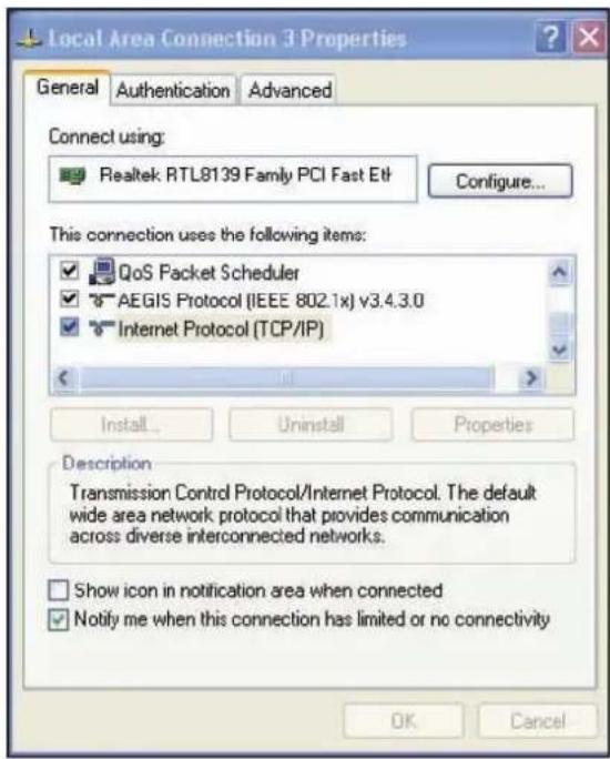
- Select Internet Protocol (TCP/IP), then click Properties.
- Select Obtain an IP address automatically if you want the IP settings to be assigned automatically. Otherwise, select Use the following IP address: and key in IP address, Subnet mask, and Default gateway.
- Select Obtain DNS server address automatically if you want the DNS server settings to be assigned automatically. Otherwise, select Use the following IP addresses: and key in the Preferred and Alternate DNS server.
- Click OK when done.

3.5 Windows Vista
- Click Start > Control Panel > Network and Sharing Center. Select Manage Network Connect at the left panel. Right-click Local Area Connection (local network your ADSL hooked up with) and select Properties.
- Select Internet Protocol Version 4(TCP/IPv4) then click Properties:
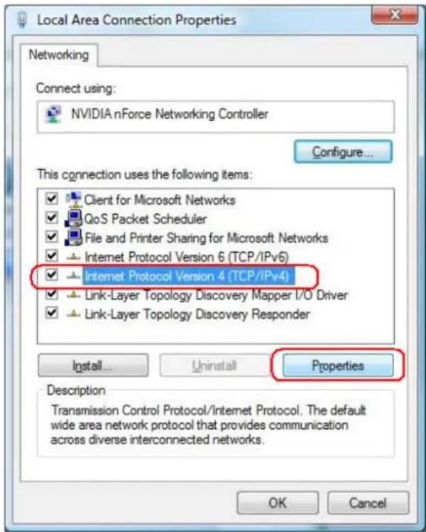
- Select Obtain an IP address automatically and Obtain DNS server address automatically. Otherwise, select Use the following IP addresses: and key in the Preferred and Alternate DNS server.
- Click OK when done.

4. Configuring via the web GUI
The Wireless Router includes a web graphics user interface (web GUI) which allows you to configure the wireless router using a web browser on your computer.
If your PC connects to the router using a cable, launch a web browser and the login page of the router's web GUI is automatically launched.
If your PC connects to the router wirelessly, you have to select the network first
- Click Start > Control Panel > Network Connections > Wireless Network Connection.
- Select a network from the Choose a wireless network window. Wait for it to connect.
- After establishing a wireless connection, launch a web browser.
4.1 To configure via the web GUI
The router's web graphics user interface (web GUI) allows you to configure the feature.
- After setting up a wired or wireless connection, launch a web browser. Enter this IP address: http://192.168.1.1

- On the login page, key in the default user name (admin) and password (admin).

- The WIRELESS ROUTER home page appears. The home page display quick links to help you easily configure the features in the wireless router.
4.2 Wireless
Configure your wireless connection, security, and other advanced parameters.
4.2.1 General
This page allows user to configure basic wireless settings.

SSID: Assign an identification string of up to 32 characters for your wireless connection.
Hide SSID: If [YES] is selected, your SSID does not show in site surveys by wireless mobile clients and they can only connect to your Wireless Router with your SSID of AP.
Country Code: The available channel differs from different countries. For example: United States is channel 1-11, European Union is channel 1-13.
Channel: The radio channel for wireless connection operation.
Wireless Mode: This field indicates the 802.11g interface mode. Select [Auto] to allow the
connection to the Wireless Router of 802.11g and 802.11b wireless mobile clients. Select [54g Protection] to enable G-Mode protection for 802.11g traffic automatically in the presence of 11b traffic.
Authentication Method: This field enables the authentication methods for wireless clients.
WPA Encryption: Enable WPA Encryption to encrypt data.
WPA Pre-Shared Key: This field requires a password of 8 to 63 characters to start the encryption process. If you leave this field blank, the default [00000000] will be assigned as your password.
WEP Encryption: Enable WEP Encryption to encrypt data.
Key Index: Set the WEP key to transmit data on your wireless.
WEP Key 1\~4: Only valid when using WEP encryption algorithm. The key must match with the AP's Key.
Passphrase: Select [WEP-64bits] or [WEP-128bits] in WEP encryption field to generate four WEP keys automatically.
Network Key Rotation Interval: This field specifies the interval (in seconds) after which a WPA group key is changed. Enter [0] (zero) to indicate that a periodic key-change is not required.
4.2.2 WPS
WPS (Wi-Fi Protected Setup) provides easy and secure establishment of a wireless network. You can configured WPS here via the by PIN code method.
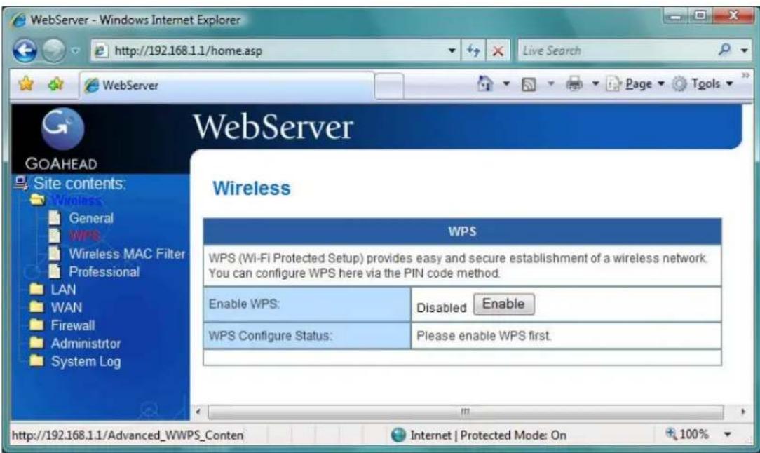
Enable WPS: Allowing Wi-Fi Protected Setup (WPS) to simplify the process of connecting any device to the wireless network. WPS support the authentication of Open system, Share key, WPA-Personal, WPA2-Personal. Not support WPA-Enterprise, WPA2-Enterprise and Radius.
AP PIN Code: Remember the PIN code of AP (the same as PIN code in the bottom of WIRELESS ROUTER). Input this PIN code in client's WPS utility and utility will configure the wireless security setting of WIRELESS ROUTER.
Client PIN Code: Key in an eight-digit number for the PIN code.
4.2.3 Wireless MAC Filter
Wireless MAC filter allows you to control packets from devices with specified MAC address in your Wireless LAN.

MAC Filter Mode: In Accept mode, WIRELESS ROUTER only accepts clients with MAC address in the list. In Reject mode, WIRELESS ROUTER will reject clients with MAC address in the list.
MAC Address: Enter the complete MAC address which contains 12 hexadecimal letters.
4.2.4 Professional
Wireless Professional Setting allows you to set up additional parameters for wireless. But default values are recommended.

Enable Radio?: Select [Yes] to enable Radio function.
Date to Enable Radio: This field defines the dates that wireless function is enabled.
Time of Day to Enable Radio: This field defines the time interval that wireless function is enabled.
Data Rate (Mbps): This field allows you to select the transmission rate. [Auto] is recommended to maximize performance.
Fragmentation Threshold: Fragmentation Threshold sets the frame size of incoming messages (ranging from 256 to 2346 bytes) used as fragmentation boundary. If the frame size is too big, the heavy interference affects transmission reliability. If the frame size is too small, it decreases transmission efficiency.
RTS Threshold: Lower the signal RTS (Request To Send) to promote the transmission efficiency in condition of noisy environment or too many clients.
DTIM Interval: DTIM (Delivery Traffic Indication Message) is included in Beacon packet. The DTIM Interval (1-255) means the period of time to wake up wireless clients from Sleep Mode. The default value is 1.
Beacon Interval: Beacon Interval means the period of time between one beacon and the next one. The default value is 100 (the unit is millisecond, or 1/1000 second). Lower the Beacon Interval to improve transmission performance in unstable environment or for roaming clients, but it will be power consuming.
4.3 LAN
Configure LAN, DHCP, and Route settings.
4.3.1 LAN IP
Configure the LAN IP of WIRELESS ROUTER. The DHCP Server dynamically changes the IP pool when you change the LAN IP.

IP Address: The LAN IP address of WIRELESS ROUTER. The Default value is 192.168.1.1.
Subnet Mask: The LAN subnet mask of WIRELESS ROUTER. The Default value is 255.255.255.0
4.3.2 DHCP Server
WIRELESS ROUTER supports up to 253 IP address for your local network. The IP address of a local machine can be assigned manually by the network administrator or obtained automatically from WIRELESS ROUTER if the DHCP server is enabled.
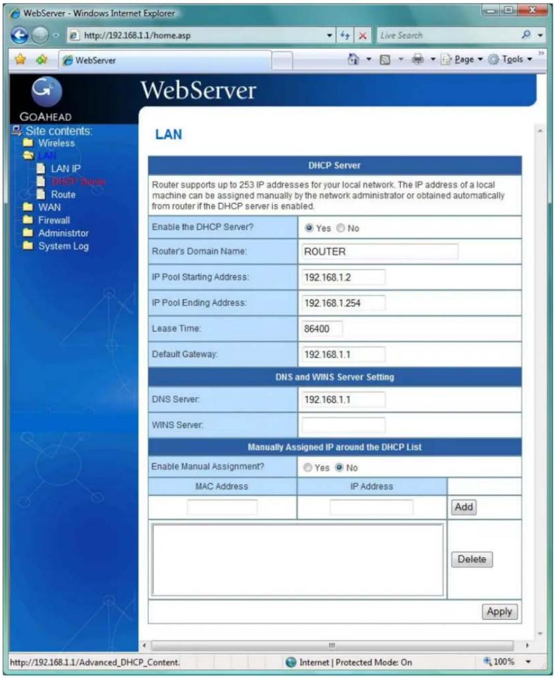
Enable the DHCP Server?: DHCP server administers and assigns IP addresses for LAN clients automatically.
WIRELESS ROUTER's Domain Name: The Domain Name for client who requests IP address from the DHCP server.
IP Pool Starting Address: The first address in the pool to be assigned by the DHCP server in LAN.
IP Pool Ending Address: This field indicates the last address in the pool to be assigned by the DHCP server in LAN.
Lease Time: The amount of connection time with the current dynamic IP address.
Default Gateway: This field indicates the IP address of gateway in your LAN.
DHCP's IP address: This field indicates the IP address of DNS to provide to clients that request IP address from DHCP server.
WINS Server: The Windows Internet Naming Service manages interaction of each PC with the Internet. If you use a WINS server, enter IP address of server here.
Enable Manual Assignment?: Enable this function to assign static IP address by manually.
MAC Address: Enter the MAC Address of each DHCP client.
IP Address: Assign an IP address for each DHCP client. The IP address should comply with the DHCP address pool you specified. The DHCP address pool contains the range of the IP address that will automatically be assigned to the clients on the network.
4.3.3 Route
This function allows you to add routing rules into WIRELESS ROUTER. It is useful if you connect several routers behind WIRELESS ROUTER to share the same connection to the Internet.

Network/Host IP: It stands for the destination network or host of a route rule. So it could be a host address, such as 「192.168.123.11」 or a network address, such as 「192.168.0.0」.
Netmask: It indicates how many bits are for network ID and subnet ID. For example: if the dotted-decimal netmask is 255.255.255.0, then it's netmask bits is 24. If the destination is a host, its netmask bits should be 32.
Gateway: It stands for the IP address of gateway where packets are routed to. The specified gateway must be reachable first. It means you have to set up a static route to the gateway beforehand.
Metric: Metric is a value of distance for the network
Interface: Network interface that the route rule applies to.
4.4 WAN
Configure the Internet connection, QoS, and Server settings.
4.4.1 Internet Connection
WIRELESS ROUTER supports several connection types to WAN. These types are selected from the dropdown menu beside WAN Connection Type. The setting fields differ depending on the connection type you selected.

WAN Connection Type: WIRELESS ROUTER supports 5 methods of obtaining the WAN IP Address:
-- Automatic IP (DHCP): Automatic gets IP address from your ISP.
-- PPPoE (ADSL): PPPoE is a common connection type used for xDSL.
-- PPTP: PPP Tunneling Protocol can support multi-protocol Virtual Private Network (VPN).
-- L2TP: Layer 2 Tunneling Protocol can support multi-protocol Virtual Private Networks (VPN)
-- Static IP (fixed IP): Use static IP address to access Network.
Get the WAN IP automatically?: This field allows you to get the WAN IP address automatically.
IP Address: This is the IP address of WIRELESS ROUTER as seen on the remote network. If you set it to 0.0.0.0, WIRELESS ROUTER will get IP address from DHCP Server automatically.
Subnet Mask: This is the Subnet Mask of WIRELESS ROUTER as seen on the remote network.
Default Gateway: This is the IP address of the default gateway that allows for contact between WIRELESS ROUTER and the remote network or host.
Connect to DNS Server automatically: This field allows you to get the DNS IP address from the remote network automatically
DNS Server 1\~2: This field indicates the IP address of DNS that WIRELESS ROUTER contacts to.

User Name: This field is only available when you set WAN Connection Type as PPPoE or PPTP.
Password: This field is only available when you set WAN Connection Type as PPPoE.
Idle Disconnect Time in seconds: Disconnect After time of inactivity (in seconds): This field is optional and allows you to configure to terminate your ISP connection after a specified period of time. This field is optional and allows you to end your ISP connection after the specified time of inactivity. A value of zero allows infinite idle time. If Tx Only is checked, the data from Internet will be skipped for counting idle time. If Tx Only is checked, Internet activity such as downloading data, is not counted as idle time.
MTU: It means Maximum Transmission Unit (MTU) of PPPoE packet.
Heart-Beat or PPTP/L2TP (VPN) Server: Please enter the server name or server IP of the authentication server of BigPond server.
Host Name: This field allows you to provide a host name for WIRELESS ROUTER. It is usually requested by your ISP.
MAC address: This field allows you to provide a unique MAC address for WIRELESS ROUTER to connect Internet. It is usually requested by your ISP.
4.4.2 Port Trigger
Port Trigger function allows you to open certain TCP or UDP ports to communicate with the computers connected to WIRELESS ROUTER. This is done by defining trigger ports and incoming ports. When the trigger port is detected, the inbound packets to the specified incoming port numbers are redirected to your computer.

Enable Port Trigger: Enable/Disable the port trigger.
Description: Enter the name of port trigger.
Trigger Port: This is the port used to trigger the application. It can be either a single port or a range of ports.
(Trigger) Protocol: This is the protocol used to trigger the special application.
Incoming Port: This is the port number on the WAN side that will be used to access the application. You may define a single port or a range of ports. You can use a comma to add multiple ports or port ranges.
(Incoming) protocol: This is the protocol used for the special application.
4.4.3 Virtual Server
To make services, like WWW, FTP, provided by a server in your local network accessible to the outside users, you should specify a local IP address to the server. Then, add the IP address and network protocol type, port number, and name of the service in the following list. Based on the list, the gateway will forward service request from outside users to the corresponding local server.

4.4.5 DDNS
Dynamic DNS (DDNS) allows you to assign an Internet domain name to a computer with a dynamic IP address. Currently, several DDNS services are embedded in WIRELESS ROUTER.  Enable the DDNS Client: Enable/Disable the DDNS server. Default setting is Disable. Server: AP Router supports type: DynDns.org. User Name or E-mail address: Enter the user name or e-mail address that you register in DynDns.org website Password or DDNS Key: Enter the password or DDNS Key that you register in DynDns.org website Hostname: Enter the hostname that you register in DynDns.org website Update Manual: Click "Update" button to update the DDNS manually.4.5 Firewall
Configure the firewall and filter mechanisms to protect your network.4.5.1 General
Enabling Firewall provides basic protection for WIRELESS ROUTER and devices behind it. If you want to filter out specified packets, please use WAN vs. LAN filter in next page. [General]
Enable Web Access from WAN?: This feature allows you to configure WIRELESS ROUTER from the Internet. If you are under Home Gateway mode, please access WIRELESS ROUTER with 8080 port (i.e. http://Your WAN IP: 8080). Port of Web Access from WAN: To specify the port used to configure WIRELESS ROUTER from the Internet. The default port is 8080. Respond Ping Request from WAN?: This feature allows you to respond to ping request from WAN.[VPN Passthorugh]
IP security VPN Passthrough: IP Security (IPSec) is a framework for a set of protocols for security at the network or packet processing layer of network verification. PPTP VPN Passthrough: PPTP is a protocol that allows corporations to extend their own corporate network through private "tunnels" over the public Internet. Click "Yes" to Enable this protocol verification. L2TP VPN Passthrough: L2TP is an extension to the Point-to-Point Protocol, which is an important component for VPNs. VPNs allow users and telecommuters to connect to their corporate intranets or extranets.4.5.2 URL Filter
To specify keyword, URL filter will block specific URL access from clients.  Date to Enable URL Filter: This field defines the dates that URL filter will be enabled. Time of Day to Enable URL Filter: This field defines the time interval that URL filter will be enabled.4.5.3 MAC Filter
MAC filter allows you to block packets from devices with specified MAC address in your LAN.  MAC Filter Mode: In Accept mode, WIRELESS ROUTER only accepts clients with MAC address in the list. In Reject mode, WIRELESS ROUTER will reject clients with MAC address in the list. MAC Address: Please enter the complete MAC address which contains 12 hexadecimal letters.4.5.4 LAN to WAN Filter
LAN vs. WAN filter allows you to block specified packets between LAN and WAN. You can first define the date and time that filter will be enabled. You can then choose the default action for filter in both directions and insert the rules for any exceptions  Enable LAN to WAN Filter?: Select [Yes] to enable filter that specify IP or port for control incoming and outgoing packets. Date to Enable LAN to WAN Filter: This field defines the dates that LAN to WAN filter will be enabled. Time of Day to Enable LAN to WAN Filter: This field defines the time interval that LAN to WAN filter will be enabled. Packets not specified will be: This field defines those LAN to WAN packets which are not specified in IP Filter Table will be accepted or dropped. Filtered ICMP packet types: This field defines a list of LAN to WAN ICMP packets type that will be filtered. For example, if you would like to filter Echo (type 8) and Echo Reply (type 0) ICMP packets, you need to enter a string with numbers separated by blank, such as, 0 5. Well-Known Applications: User Defined, WWW, Telnet, FTP4.6 Administration
Configure the system and upgrade the firmware of WIRELESS ROUTER.4.6.1 Status
This page is to view the Wireless system status, such as System Information, Internet Configurations and Local Network information. 4.6.2 System
 Remote Log Server: This field allows assigning a remote server to record log messages of WIRELESS ROUTER. If you leave it blank, the system will record up to 1024 messages on WIRELESS ROUTER. Time Zone: The standard time in your area or locality. NTP Server: To synchronize your system time with NTP Server.4.6.3 Firmware Upgrade
Follow instructions listed below:
1. Check if any new version of firmware is available on website. 2. Download a proper version to your local machine. 3. Specify the path of and name of the downloaded file in the [New Firmware File]. 4. Click [Upload] to upload the file to WIRELESS ROUTER. Uploading process takes about three minutes. 5. "After receiving a correct firmware file, WIRELESS ROUTER will automatically start the upgrade process. The system reboots after the upgrading process is finished."Note:
1. For a configuration parameter existing both in the old and new firmware, its setting will be kept during the upgrade process. 2. In case the upgrade process fails, WIRELESS ROUTER enters the emergency mode automatically. The LED signals at the front of WIRELESS ROUTER will indicate such situation. Use the Firmware Restoration utility on the CD to do system recovery4.6.4 Restore/Save/Upload Setting
This function allows you to save current settings of WIRELESS ROUTER to a file, or load settings from a file.  Factory default: Click [Factory default] to restore the router to its factory default settings and delete all the current settings. Wait for a while until the router reboots. Save settings: Click the [Save] button to save current setting of WIRELESS ROUTER into a file. (Note: While you save current settings to a file, it will be saved to flash as well.) Restore settings: Specify the path and name of setting file. Then click [Upload] to write the file to WIRELESS ROUTER. Please wait 30 seconds until WIRELESS ROUTER reboots.4.7 System Log
Monitor the status and various system logs.4.7.1 General Log
The log file keeps a running log of events and activities occurring on the device. The log always displays recent logs. When the device is rebooted, the log would not be cleared.  Boot time: Elapsed time since system boot4.7.2 System Status
This page is to view the Wireless system status. 4.7.3 DHCP Leases
This page displays the DHCP leases log, such as Hose Name, MAC Address, IP address, and Expires In information. 4.7.4 Wireless Log
This page displays wireless system log, such as wireless mode, channel, and Stations list.  Radio Control: To enable wireless radio or disable.4.7.5 Routing Table
A routing table contains the information necessary to forward a packet along the best path toward its destination. Each packet contains information about its origin and destination. When a packet is received, a network device examines the packet and matches it to the routing table entry providing the best match for its destination. The table then provides the device with instructions for sending the packet to the next hop on its route across the network.  Destination: The IP address of the packet's final destination. The destination can be an IP address or a class-based, sub-netted, or super-netted network ID. Gateway: The IP address to which the packet is forward. Netmask: Includes directly-attached subnets, indirect subnets that are not attached to the device but can be accessed through one or more hops, and default routes to use for certain types of traffic or when information is lacking. Flags: Possible flags include → U: Route is up. H: Target is a host. G: Use Gateway C: Cache entry ! :Reject route Metric: A number used to indicate the cost of the route so that the best route, among potentially multiple routes to the same destination, can be selected. Ref: Number of reference to this route. Use: Count of lookups for the route. Iface: Interface to which packets for this route will be sent.


- ADVANTEK NETWORKS
- WIRELESS – G BROADBAND ROUTER
- USERS MANUAL
- FCC WARNING
- IMPORTANT NOTE
- MODULAR APPROVAL STATEMENT
- CE MARK WARNING
- COPYRIGHT
- TRADEMARKS
- TABLE OF CONTENTS
- INTRODUCTION......5
- SETTING UP THE HARDWARE....9
- CONFIGURING THE NETWORK CLIENT....9
- CONFIGURING VIA THE WEB GUI ....17
- INTRODUCTION
- 1.1 FEATURES
- INTERNET ACCESS FEATURES
- ADVANCED INTERNET FUNCTIONS
- WIRELESS FEATURES
- LAN FEATURES
- CONFIGURATION AND MANAGEMENT
- SECURITY FEATURES
- 1.2 PACKAGE CONTENTS
- 1.3 LEDS INDICATION & CONNECTORS OF WIRELESS ROUTER
- 1.4 SYSTEM REQUIREMENTS
- 1.5 BEFORE YOU PROCEED
- SETTING UP THE HARDWARE
- 2.1 SETTING UP A WIRED CONNECTION
- 2.2 SETTING UP A WIRELESS CONNECTION
- CONFIGURING THE NETWORK CLIENT
- 3.1 WINDOWS 9X/ME
- 3.2 WINDOWS NT4.0
- 3.3 WINDOWS 2000
- 3.4 WINDOWS XP
- 3.5 WINDOWS VISTA
- CONFIGURING VIA THE WEB GUI
- 4.1 TO CONFIGURE VIA THE WEB GUI
- 4.2 WIRELESS
- 4.2.1 GENERAL
- 4.2.2 WPS
- 4.2.3 WIRELESS MAC FILTER
- 4.2.4 PROFESSIONAL
- 4.3 LAN
- 4.3.1 LAN IP
- 4.3.2 DHCP SERVER
- 4.3.3 ROUTE
- 4.4 WAN
- 4.4.1 INTERNET CONNECTION
- 4.4.2 PORT TRIGGER
- 4.4.3 VIRTUAL SERVER
- 4.4.4 DMZ
- 4.4.5 DDNS
- 4.5 FIREWALL
- 4.5.1 GENERAL
- [GENERAL]
- [VPN PASSTHORUGH]
- 4.5.2 URL FILTER
- 4.5.3 MAC FILTER
- 4.5.4 LAN TO WAN FILTER
- 4.6 ADMINISTRATION
- 4.6.1 STATUS
- 4.6.2 SYSTEM
- 4.6.3 FIRMWARE UPGRADE
- FOLLOW INSTRUCTIONS LISTED BELOW
- NOTE
- 4.6.4 RESTORE/SAVE/UPLOAD SETTING
- 4.7 SYSTEM LOG
- 4.7.1 GENERAL LOG
- 4.7.2 SYSTEM STATUS
- 4.7.3 DHCP LEASES
- 4.7.4 WIRELESS LOG
- 4.7.5 ROUTING TABLE
Brand : Advantek Networks
Model : AWR-654GR
Category : Router