
CX111 - Wi-Fi repeater Juniper - Free user manual and instructions
Find the device manual for free CX111 Juniper in PDF.


| Product Type | Cellular Broadband Data Bridge (3G) |
| Model | CX111 |
| Brand | Juniper Networks |
| Wireless Technology | 3G (UMTS/HSPA) via USB/ExpressCard modems |
| Interfaces | 1x Gigabit Ethernet (RJ-45) with PoE support |
| Power Supply | Power over Ethernet (PoE) IEEE 802.3af, ~3.5W per modem, or external power adapter (included) |
| Dimensions (approx.) | 150 x 80 x 30 mm (5.9 x 3.1 x 1.2 in) |
| Weight (approx.) | 300 g (10.6 oz) |
| Management Interface | Web-based UI (VLAN 3900, IP 192.168.0.1/24) |
| Operating Modes | Always-on or Dial-on-demand (default: dial-on-demand, 20 min idle timeout) |
| Modem Support | Up to 2 modems (USB or ExpressCard), user-selectable priority; 50+ certified modems |
| Network Features | Pass-through mode (no NAT), DHCP relay, VLAN tagging (data/management) |
| Signal Monitoring | 3G signal strength, connection status, traffic statistics via web UI |
| Backup Connectivity | Supports RPM probes and monitoring scripts for automatic failover |
| Software Requirements | Junos OS 10.1R1 or later, CX111 firmware 1.6.10 or later |
| Compatibility | Juniper J Series and SRX Series (SRX100, SRX200, SRX650) |
| Certifications | CE, FCC (typical) |
| Temperature Range | 0°C to 40°C (32°F to 104°F) |
| Humidity | 5% to 95% non-condensing |
| Cleaning | Wipe with a dry, soft cloth; do not use liquids or sprays |
| Safety | Use only provided power supply; avoid exposure to water or excessive heat |
| Repair & Spare Parts | Contact Juniper authorized service center; no user-serviceable parts inside |
Frequently Asked Questions - CX111 Juniper
User questions about CX111 Juniper
0 question about this device. Answer the ones you know or ask your own.
Ask a new question about this device
Download the instructions for your Wi-Fi repeater in PDF format for free! Find your manual CX111 - Juniper and take your electronic device back in hand. On this page are published all the documents necessary for the use of your device. CX111 by Juniper.
USER MANUAL CX111 Juniper
CONFIGURING THE CX111 FOR J SERIES AND BRANCH SRX SERIES DEVICES
How to Configure the CX111 as a Primary or Backup 3G WAN Connection Option for Junos OS-Based Platforms
Table of Contents
Introduction 3
Scope 3
Design Considerations....3
Supported Hardware 3
Software Requirements ....3
Card Compatibility ....3
Card Activation ....3
Description and Deployment Scenario 4
Management Interface 4
Power over Ethernet 5
Dial Modes....5
Deployment Scenarios....5
CX111 Used for Primary Connectivity 5
Enabling PoE....6
Management Access 7
CX111 Used for Backup 9
Detecting Network Failures Using RPM Probes 10
Monitoring....12
Summary 13
About Juniper Networks....14
Table of Figures
Figure 1: Deployment model .... 4
Figure 2: 3G network as the primary link .... 5
Figure 3: Management access ....7
Figure 4: Interface backup....9
Figure 5: Prefix watch ....10
Figure 6: Modem status .....12
Figure 7: Modem statistics....13
Introduction
Due to their ubiquitous presence, the use of third-generation (3G) wireless networks has become a common deployment option for both primary and backup connectivity. With the introduction of Juniper Networks ^® CX111 Cellular Broadband Data Bridge, Juniper offers a simple way to provide wireless connectivity as either a backup or primary connection for Juniper Networks J Series Services Routers and branch SRX Series Services Gateways products.
Scope
The purpose of this application note is to provide an overview that shows how to configure and deploy the CX111 as a primary or backup 3G WAN connectivity option for Juniper Networks SRX Series and J Series platforms.
Design Considerations
Supported Hardware
- Juniper Networks SRX Series Services Gateways (SRX100 Services Gateway, the SRX200 line, or SRX650 Services Gateway)
• Juniper Networks J Series Services Routers
Software Requirements
• Juniper Networks Junos OS release 10.1R1 or later
- There is a Dynamic Host Configuration Protocol (DHCP) memory leak issue with earlier Junos OS versions when configured with the CX111
- CX111 firmware 1.6.10 or later
Card Compatibility
As of the date of this writing, about 50 different USB and ExpressCard modems have been certified to work with the CX111. The latest list of modems can be found here: www.juniper.net/techpubs/hardware/junos-cx/cx111/index.html.
Card Activation
Before cards can be used, they need to be programmed with the subscriber information required to access the service provider's network. This is normally referred to as the card activation process. When service is purchased, the carrier will request the card's ESN number, normally found printed on the wireless card. This number is then used for card identification by the different activation protocols.
Cards directly purchased from the wireless carrier can ship pre-activated, or sometimes they will ship with a companion software used to perform the initial activation. In either case, cards already activated do not have to be reactivated.
Optionally, the cards can be activated from the CX111. This requires users to log into the CX111's UI using a Web browser.
Description and Deployment Scenario
The CX111 ships with a default configuration that should accommodate most deployment scenarios. The deployment model assumes that the CX111 is connected to a DHCP-enabled interface.

flowchart
graph TD
    A["Server 1"] --> B["SRX210"]
    C["Server 2"] --> B
    D["Server 3"] --> B
    E["Server 4"] --> B
    B --> F["Office"]
    B --> G["CX111"]
    H["Internet Tower"] --> I["Data Tower"]
    style H fill:#f9f,stroke:#333
    style I fill:#ccf,stroke:#333
ge-0/0/0.0 is connected to the Internet ge-0/0/1.0 is connected to the CX111
Figure 1: Deployment model
The CX111 will maintain the wireless modem (or modems, if more than one modem is used) in a disconnected state, triggering a new connection as soon as the SRX Series/J Series requests a new lease. The modem(s) will be disconnected as soon as the lease expires, and only reconnected when that gateway requires another new lease.
When using the 3G link as the primary connection, long lease times can be used, as generally there won't be a need to constantly connect and disconnect the line. On the other hand, if the CX111 is used to provide a backup connection, short lease times (in the order of a minute) are commonly used so that, when the primary link is active, the backup link can be disabled, triggering a disconnection, in the worse case, after a lease time.
The CX111 assigns the address received from the wireless service provider to the gateway (normally a public address). For obvious reasons, only a single device can be connected to the CX111 at any given time, or else multiple devices will contend for the only address passed to the CX111. The CX111 works in "pass through" mode, simply relaying all traffic from the wireless network to the DHCP client.
Management Interface
The CX111 provides a web-based management interface, and it can be accessed even when 3G modems are not used. Since “pass through” mode is used instead of a routed connection bridge that doesn’t do Network Address Translation (NAT), the management interface cannot be accessed through the normal data channel.
The management interface is still accessible through the Ethernet port, but VLAN tagging is used to separate management from data traffic using the following parameters
Table 1: Management Network
| CARD MODEL WIRELESS TECHNOLOGY |
| Management subnet 192.168.0.0/24 |
| Management address 192.168.0.1 |
| VLAN ID 3900 |
Power over Ethernet
When available, Power over Ethernet (PoE) can be used to power the CX111. In the event that the CX111 is connected through a switch or a gateway that does not support PoE, an external power supply can be used (provided with the basic install kit).
When PoE is used, the device will require about 3.5 watts of power per modem connected, so plan your power budget accordingly.
Dial Modes
The CX111 can be configured in two modes: "always on" or "dial on-demand." In the "always on" mode, the CX111 connects to the 3G network after booting. The connection is always maintained, as long as there are no network or connectivity problems.
In "dial on-demand" mode, the CX111 only initiates a connection when it receives traffic from the interface connecting the CX111 and gateway. In particular, DHCP request messages will trigger a connection. Similarly, the connection will be dropped after a configurable inactivity timeout.
Regardless of the mode, the CX111 can accept multiple cards simultaneously. In the event of a failure or inability to connect, the remaining card(s) will be used. The connection priority is user configurable through the CX111's management interface.
The default mode at shipping is 'dial on-demand' and set at 20 minutes idle timeout. Most carriers prefer the modem to disconnect if there is no interesting traffic. After the modem times out, the DHCP requests from the SRX Series device will result in a 192.168.30.x/24 response from the CX111. If interesting traffic is observed by the CX111, the modem re-dials. Modem connection takes about 15 to 20 seconds generally. After that, the next DHCP request from the SRX Series device will fetch the actual 3G IP address and internet connection is re-established.
Deployment Scenarios
In the following section, we will discuss several common deployment scenarios and provide the associated configurations.
CX111 Used for Primary Connectivity
This first scenario shows the gateway configuration when the 3G network is used as the primary WAN link. This can be achieved by simply connecting the CX111 to any interface in the untrust zone. On the SRX Series device, this is ge-0/0/0 when using the default configuration.

flowchart
graph TD
    A["Desktops"] --> B["SRX210"]
    C["Desktops"] --> B
    D["Desktops"] --> B
    B --> E["CX111"]
    E --> F["OFFICE"]
    G["INTERNET"] --> H["Wireless Tower"]
    I["192.168.1.0/24 Trust Zone"] --> B
    J["ge-0/0/0.0 connected to the CX111"] --> E
Figure 2: 3G network as the primary link
The relevant sections of the default configuration are shown here, for completeness.
set system services dhcp router 192.168.1.1
set system services dhcp pool 192.168.1.0/24 address-range low 192.168.1.2
set system services dhcp pool 192.168.1.0/24 address-range high 192.168.1.254
set system services dhcp propagate-settings ge-0/0/0.0
set interfaces interface-range interfaces-trust member ge-0/0/1
set interfaces interface-range interfaces-trust member fe-0/0/2
set interfaces interface-range interfaces-trust member fe-0/0/3
set interfaces interface-range interfaces-trust member fe-0/0/4
set interfaces interface-range interfaces-trust member fe-0/0/5
set interfaces interface-range interfaces-trust member fe-0/0/6
set interfaces interface-range interfaces-trust member fe-0/0/7
set interfaces interface-range interfaces-trust unit 0 family ethernet-switching vlan members vlan-trust
set interfaces ge-0/0/0 unit 0
set interfaces vlan unit 0 family inet address 192.168.1.1/24
set security nat source rule-set trust-to-untrust from zone trust
set security nat source rule-set trust-to-untrust to zone untrust
set security nat source rule-set trust-to-untrust rule source-nat-rule match
source-address 0.0.0.0/0
set security nat source rule-set trust-to-untrust rule source-nat-rule then
source-nat interface
set security zones security-zone trust host-inbound-traffic system-services all
set security zones security-zone trust host-inbound-traffic protocols all
set security zones security-zone trust interfaces vlan.0
set security zones security-zone untrust interfaces ge-0/0/0.0 host-inbound-traffic system-services dhcp
set security zones security-zone untrust interfaces ge-0/0/0.0 host-inbound-traffic system-services tftp
set security policies from-zone trust to-zone untrust policy trust-to-untrust match source-address any
set security policies from-zone trust to-zone untrust policy trust-to-untrust match destination-address any
set security policies from-zone trust to-zone untrust policy trust-to-untrust match application any
set security policies from-zone trust to-zone untrust policy trust-to-untrust then permit
set vlans vlan-trust vlan-id 3
set vlans vlan-trust 13-interface vlan.0
Enabling PoE
On SRX Series devices, it is possible to use PoE to power the CX111. The default configuration has PoE enabled on every PoE-capable interface, so users only have to connect the CX111 to a PoE-capable port. Enabling PoE only requires the addition of the following configuration.
/* The priority is optional but it will make sure that, if two many devices are being powered, the bridge will be given a high priority and will not be powered off */ set poe interface ge-0/0/0 priority high
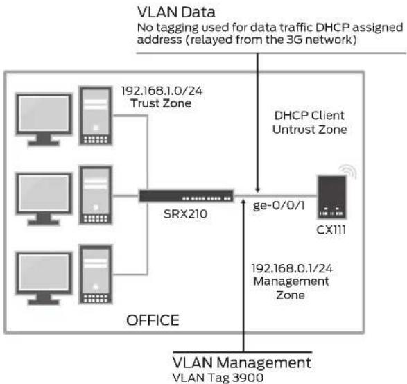
Management Access
A VLAN-tagged logical interface can be used to provide access to the CX111's management console. NAT can also be used to facilitate access from any device behind the gateway, eliminating the need for complex routing (as all traffic to the CX111's management interface will be translated as if it originated from the management subnet).
flowchart
graph TD
    A["Office"] --> B["192.168.0.1/24 Management Zone"]
    B --> C["SRX210"]
    C --> D["DHCP Client Untrust Zone"]
    D --> E["CX111"]
    F["VLAN Data\nNo tagging used for data traffic DHCP assigned address (relayed from the 3G network)"] --> C
    G["VLAN Management\nVLAN Tag 3900"] --> C
    style A fill:#f9f,stroke:#333
    style B fill:#ccf,stroke:#333
    style C fill:#cff,stroke:#333
    style D fill:#ffc,stroke:#333
    style E fill:#cfc,stroke:#333
    style F fill:#fcc,stroke:#333
Figure 3: Management access
/* The vlan.2 interface is the L3 interface of the data VLAN, connecting to the Bridge */ set system services dhcp propagate-settings vlan.2
/* Interface ge-0/0/0 has 2 VLANS configured, data and management */ set interfaces ge-0/0/0 description "Connection to CX111" set interfaces ge-0/0/0 unit 0 family ethernet-switching port-mode trunk set interfaces ge-0/0/0 unit 0 family ethernet-switching vlan members data set interfaces ge-0/0/0 unit 0 family ethernet-switching vlan members management set interfaces ge-0/0/0 unit 0 family ethernet-switching native-vlan-id data
/* vlan.0 connects to the untrust network */ set interfaces vlan unit 0 family inet address 192.168.1.1/24 /* vlan.2 connects to the bridge (untagged) */ set interfaces vlan unit 2 family inet dhcp client-identifier ascii SRX-GW /* vlan.3900 connects to the bridge's management subnet */ set interfaces vlan unit 3900 family inet address 192.168.0.2/24
/* VLANs */ set vlans data vlan-id 2 set vlans data l3-interface vlan.2 set vlans management vlan-id 3900 set vlans management l3-interface vlan.3900 set vlans vlan-trust vlan-id 3 set vlans vlan-trust l3-interface vlan.0
/* NAT rule for Internet access */ set security nat source rule-set trust-to-untrust from zone trust set security nat source rule-set trust-to-untrust to zone untrust set security nat source rule-set trust-to-untrust rule source-nat-rule match
source-address 0.0.0.0/0
set security nat source rule-set trust-to-untrust rule source-nat-rule then source-nat interface
/* NAT rule used for management access to the CX111*/
set security nat source rule-set trust-to-management from zone trust
set security nat source rule-set trust-to-management to zone management
set security nat source rule-set trust-to-management rule nat-to-CX111 match source-address 0.0.0.0/0
set security nat source rule-set trust-to-management rule nat-to-CX111 match destination-address 0.0.0.0/0
set security nat source rule-set trust-to-management rule nat-to-CX111 then source-nat interface
/* Security policies and zones */
set security zones security-zone trust host-inbound-traffic system-services all set security zones security-zone trust host-inbound-traffic protocols all set security zones security-zone trust interfaces vlan.0
set security zones security-zone untrust interfaces vlan.2 host-inbound-traffic system-services dhcp
set security zones security-zone untrust interfaces vlan.2 host-inbound-traffic system-services tftp
set security zones security-zone management interfaces vlan.3900
set security policies from-zone trust to-zone untrust policy trust-to-untrust match source-address any
set security policies from-zone trust to-zone untrust policy trust-to-untrust match destination-address any
set security policies from-zone trust to-zone untrust policy trust-to-untrust match application any
set security policies from-zone trust to-zone untrust policy trust-to-untrust then permit
set security policies from-zone trust to-zone management policy CX111-management-access match source-address any
set security policies from-zone trust to-zone management policy CX111-management-access match destination-address any
set security policies from-zone trust to-zone management policy CX111-management-access match application junos-http
set security policies from-zone trust to-zone management policy CX111-management-access match application junos-ping
set security policies from-zone trust to-zone management policy CX111-management-access then permit
CX111 Used for Backup
In this example, the CX111 will only be used when the primary interface is down. This is shown mostly for illustrative purposes, as only a failure in the primary interface will trigger a failover.
Also, this example can only be used with the CX111 operating in "always on" mode, as once connected, the DHCP requests from the SRX Series will keep the connection up. (Increasing the lease times is not a good idea, since there are no guarantees that, after a new connection, the modem will be assigned the same IP. Thus, this situation requires short lease times to make sure that the gateway is notified of the address change).

flowchart
graph TD
    A["Server 1"] --> B["SRX210"]
    C["Server 2"] --> B
    D["Server 3"] --> B
    E["Server 4"] --> B
    B --> F["Internet"]
    G["Office"] --> B
    H["CX111"] --> B
    I["192.168.1.0/24 Trust Zone"] --> B
ge-0/0/0.0 is connected to the Internet ge-0/0/1.0 is connected to the CX111
Figure 4: Interface backup
/* Interface Configs */
set interfaces interface-range Trust member-range fe-0/0/2 to fe-0/0/6
set interfaces interface-range Trust unit 0 family ethernet-switching port-mode access
set interfaces interface-range Trust unit 0 family ethernet-switching vlan members Trust

/* Main Internet Link */
set interfaces ge-0/0/0 unit 0 family inet address 198.0.0.2/24

/* CX111 backup link */
set interfaces ge-0/0/1 unit 0 family inet dhcp

set vlans default l3-interface vlan.1
set interfaces vlan unit 1 description Trust
set interfaces vlan unit 1 family inet address 192.168.1.1/24

/* Default route points to the primary link and it takes precedence over the DHCP assigned default */
set routing-options static route 0.0.0.0/0 next-hop 198.0.0.1

/* NAT Configuration */
set security nat source rule-set Outbound-NAT from zone trust
set security nat source rule-set Outbound-NAT to zone untrust
set security nat source rule-set Outbound-NAT rule Nat-All match source-address 0.0.0.0/0
set security nat source rule-set Outbound-NAT rule Nat-All match destination-address 0.0.0.0/0
set security nat source rule-set Outbound-NAT rule Nat-All then source-nat
interface
/* Security Zones */
set security zones security-zone untrust interfaces ge-0/0/0.0 host-inbound-traffic system-services ping
set security zones security-zone untrust interfaces ge-0/0/1.0 host-inbound-traffic system-services dhcp
set security zones security-zone trust host-inbound-traffic system-services ping set security zones security-zone trust interfaces vlan.1 host-inbound-traffic system-services dhcp
set security zones security-zone trust interfaces vlan.1 host-inbound-traffic system-services ping
set security zones security-zone trust interfaces vlan.1 host-inbound-traffic system-services ssh
/* Allow outboud traffic from trust to untrust */
set security policies from-zone trust to-zone untrust policy permit-outbound match source-address any
set security policies from-zone trust to-zone untrust policy permit-outbound match destination-address any
set security policies from-zone trust to-zone untrust policy permit-outbound match application any
set security policies from-zone trust to-zone untrust policy permit-outbound then permit
Detecting Network Failures Using RPM Probes
Although quite simple, our previous example presents a major drawback—the primary interface's status is not always a good indicator of the network's connectivity. In some instances, when layer 2 protocols are not able to detect end-to-end failures, or when multiple network hops separate the Juniper Networks SRX210 Services Gateway from remote resources, other means to trigger a failover are desired.
This example shows how to configure a set of watch prefixes which, when they are not present in the routing table, will enable the dialer interface. Static routes with Bidirectional Forwarding Detection (BFD) monitoring or routing protocols can be used to dynamically change the status of the routes in the routing table.
The main advantage of this approach is that real-time performance monitoring (RPM) probes do not require any special routing protocol support or the use of BFD. RPM probes can be configured to use standard Internet Control Message Protocol (ICMP) messages, HTTP get requests, or TCP/UDP pings to verify end-to-end connectivity. The RPM monitor scripts can be downloaded from the following URL: www.juniper.net/support/products/cx/#sw

flowchart
graph TD
    A["Office Data Center"] -->|10.0.1.0/24 Trust Zone| B["SRX210"]
    B --> C["INTERNET WAN"]
    C --> D["SRX Series Cluster"]
    D --> E["Data"]
    D --> F["Finance"]
    D --> G["Video"]
    D --> H["Apps"]
    B --> I["Default route points to the d10.0 interface d10.0 monitors the 10/8 prefix"]
    D --> J["10/8 prefix advertised through OSPF"]
Figure 5: Prefix watch
Even though this example builds on the previous one, in order to present a complete working scenario, the full configuration is shown below.
/* Enable the commit script. The commit script must be stored under /var/db/scripts/commit */
set system scripts commit allow-transients
set system scripts commit file rpm-monitor-config.xslt
/* Enable the event script. The script file must be stored under /var/db/scripts/event */
set event-options event-script file rpm-monitor.xslt
/* Local dhcp server configuration */
/* This server assigns addresses to the hosts in the Trust network */
set system services dhcp pool 192.168.1.0/24 address-range low 192.168.1.2
set system services dhcp pool 192.168.1.0/24 address-range high 192.168.1.254
set system services dhcp pool 192.168.1.0/24 router 192.168.1.1
/* This configuration creates a log file named rpm-monitor containing the login messages from the script */
set system syslog file rpm-monitor user warning
set system syslog file rpm-monitor match cscript
/* Interface Configs */
set interfaces interface-range Trust member-range fe-0/0/2 to fe-0/0/6
set interfaces interface-range Trust unit 0 family ethernet-switching port-mode access
set interfaces interface-range Trust unit 0 family ethernet-switching vlan members Trust
set interfaces ge-0/0/0 unit 0 family inet address 198.0.0.2/24
set interfaces vlan description CX111-data
set interfaces vlan unit 1 description Trust
set interfaces vlan unit 1 family inet address 192.168.1.1/24
set vlans default l3-interface vlan.1
/* The backup interface should be normally disabled */
/* The monitoring scripts point to an RPM probe and, if the probe fails, the script will enable the backup interface */
set interfaces ge-0/0/1 unit 0 apply-macro rpm-monitor-server1 test-name server1
set interfaces ge-0/0/1 unit 0 apply-macro rpm-monitor-server1 test-owner rpm-monitor-probes
set interfaces ge-0/0/1 unit 0 disable
set interfaces ge-0/0/1 unit 0 family inet dhcp
/* RPM probe configuration */
/* Note that we are using the primary link address as the source so, when the backup link is enabled, the probes will still fail unless the primary link comes back up. This script pings destination 'target' address. Wait for 5' ping failures and has a '5 second' probe interval. After 5 pings, the test waits for 15 seconds before starting the pings again. */
set services rpm probe rpm-monitor-probes test server1 probe-type icmp-ping
set services rpm probe rpm-monitor-probes test server1 target address
96.17.23.148
set services rpm probe rpm-monitor-probes test server1 probe-count 5
set services rpm probe rpm-monitor-probes test server1 probe-interval 5
set services rpm probe rpm-monitor-probes test server1 test-interval 15
set services rpm probe rpm-monitor-probes test server1 source-address 10.0.1.20
/* Default route pointing to the primary link */
set routing-options static route 0.0.0.0/0 next-hop 198.0.0.1
/* NAT configuration */
set security nat source rule-set Outbound-NAT from zone trust
set security nat source rule-set Outbound-NAT to zone untrust
set security nat source rule-set Outbound-NAT rule Nat-All match source-address 0.0.0.0/0
set security nat source rule-set Outbound-NAT rule Nat-All match destination-address 0.0.0.0/0
set security nat source rule-set Outbound-NAT rule Nat-All then source-nat interface
/* Zones and policies */
set security zones security-zone untrust interfaces ge-0/0/0.0 host-inbound-traffic system-services ping
set security zones security-zone untrust interfaces ge-0/0/1.0 host-inbound-traffic system-services dhcp
set security zones security-zone trust host-inbound-traffic system-services ping set security zones security-zone trust interfaces vlan.1 host-inbound-traffic system-services dhcp
set security zones security-zone trust interfaces vlan.1 host-inbound-traffic system-services ping
set security zones security-zone trust interfaces vlan.1 host-inbound-traffic system-services ssh
set security policies from-zone trust to-zone untrust policy permit-outbound match source-address any
set security policies from-zone trust to-zone untrust policy permit-outbound match destination-address any
set security policies from-zone trust to-zone untrust policy permit-outbound match application any
set security policies from-zone trust to-zone untrust policy permit-outbound then permit
Monitoring
The 3G signal strength and connection status can be monitored from the CX111's management interface, which is found under status -> device info tab.
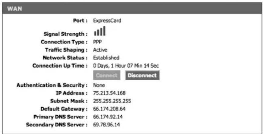
Figure 6: Modem status
Traffic statistics can be found under the Status->Statistics page.
WAN DEVICE #1(EXPRESSCARD PORT) STATISTICS
Sent KiloBytes : 4
Sent Packets : 33
Sent Packets Dropped: 0
Received KiloBytes : 3
Received Packets: 30
Received Packets Dropped: 0
Figure 7: Modem statistics
When using the RPM monitor scripts, it is quite useful to look at the script logs. These logs record events such as probe failures, enabling/disabling of the backup interface, etc. Using the configuration shown in the last example, the logs can be viewed with the "show log rpm-monitor" command.
# run show log rpm-monitor
Jan 22 05:15:48 SRX210-Home cscript: rpm-monitor: Triggered by ping_test_up test server1 owner rpm-monitor-probes
Jan 22 05:15:48 SRX210-Home cscript: rpm-monitor: RPM probe up flagged, but there is nothing to do with the logical interfaces
Jan 22 05:16:59 SRX210-Home cscript: rpm-monitor: Triggered by ping_test_up test server1 owner rpm-monitor-probes
Jan 22 05:16:59 SRX210-Home cscript: rpm-monitor: RPM probe up flagged, but there is nothing to do with the routes
The result of the RPM probes can be viewed with the following command:
pato@SRX210-Home# run show services rpm history-results
| Owner, Test | Probe received | Round trip time |
| rpm-monitor-probes, server1 Fri Jan 22 05:29:40 2010 | 192057 usec | |
| rpm-monitor-probes, server1 Fri Jan 22 05:29:45 2010 | 194821 usec | |
| rpm-monitor-probes, server1 Fri Jan 22 05:29:50 2010 | 197966 usec | |
| rpm-monitor-probes, server1 Fri Jan 22 05:29:55 2010 | 188755 usec | |
| rpm-monitor-probes, server1 Fri Jan 22 05:30:00 2010 | 189775 usec | |
| rpm-monitor-probes, server1 Fri Jan 22 05:30:16 2010 | 199006 usec | |
| rpm-monitor-probes, server1 Fri Jan 22 05:30:21 2010 | 190135 usec | |
| rpm-monitor-probes, server1 Fri Jan 22 05:30:26 2010 | 190896 usec | |
| rpm-monitor-probes, server1 Fri Jan 22 05:30:31 2010 | 192937 usec | |
| rpm-monitor-probes, server1 Fri Jan 22 05:30:36 2010 | 203084 usec |
Summary
As more and more wireless carriers expand their coverage and upgrade their networks to offer 3G wireless data services, enterprises worldwide can look to use 3G as a backup connectivity solution for many deployments and in some cases, even use 3G wireless as primary data access.
Juniper Networks SRX Series Services Gateways provide world-class security and routing features, and now combined with the flexible and optimized CX111 Cellular Broadband Data Bridge, the SRX Series can offer additional WAN connectivity solutions to customers for increased WAN uptime coupled with reduced operational expense. The CX111 is simple to configure and deploy, which can be installed easily in existing and new SRX Series and J Series deployments.
About Juniper Networks
Juniper Networks, Inc. is the leader in high-performance networking. Juniper offers a high-performance network infrastructure that creates a responsive and trusted environment for accelerating the deployment of services and applications over a single network. This fuels high-performance businesses. Additional information can be found at www.juniper.net.
Corporate and Sales Headquarters
Juniper Networks, Inc.
1194 North Mathilda Avenue
Sunnyvale, CA 94089 USA
Phone: 888.JUNIPER (888.586.4737)
or 408.745.2000
Fax: 408.745.2100
www.juniper.net
APAC Headquarters
Juniper Networks (Hong Kong)
26/F, Cityplaza One
1111 King's Road
Taikoo Shing, Hong Kong
Phone: 852.2332.3636
Fax: 852.2574.7803
EMEA Headquarters
Juniper Networks Ireland
Airside Business Park
Swords, County Dublin, Ireland
Phone: 35.31.8903.600
EMEA Sales: 00800.4586.4737
Fax: 35.31.8903.601
To purchase Juniper Networks solutions, please contact your Juniper Networks representative at 1-866-298-6428 or authorized reseller.
Copyright 2009 Juniper Networks, Inc. All rights reserved. Juniper Networks, the Juniper Networks logo, Junos. NetScreen, and ScreenOS are registered trademarks of Juniper Networks, Inc. In the United States and other countries. All other trademarks, service marks, registered marks, or registered service marks are the property of their respective owners. Juniper Networks assumes no responsibility for any inaccuracies in this document. Juniper Networks reserves the right to change, modify, transfer, or otherwise revise this publication without notice.
3500184-001-EN Mar 2010
Printed on recycled paper

- CONFIGURING THE CX111 FOR J SERIES AND BRANCH SRX SERIES DEVICES
- Table of Contents
- Table of Figures
- Introduction
- Scope
- Design Considerations
- Supported Hardware
- Software Requirements
- Card Compatibility
- Card Activation
- Description and Deployment Scenario
- Management Interface
- Power over Ethernet
- Dial Modes
- Deployment Scenarios
- CX111 Used for Primary Connectivity
- Enabling PoE
- Management Access
- CX111 Used for Backup
- interface
- Detecting Network Failures Using RPM Probes
- Monitoring
- WAN DEVICE #1(EXPRESSCARD PORT) STATISTICS
- Figure 7: Modem statistics
- Summary
- About Juniper Networks
- Corporate and Sales Headquarters
- APAC Headquarters
- EMEA Headquarters
Brand : Juniper
Model : CX111
Category : Wi-Fi repeater