
DN-16050 - Security Camera Digitus - Free user manual and instructions
Find the device manual for free DN-16050 Digitus in PDF.


| Product Type | Network Camera (Indoor) |
| Image Sensor | 1/3.6" CMOS |
| Effective Pixels | 738 (H) x 480 (V) |
| Lens | f3.6mm, F2.0 |
| Viewing Angle | 80° |
| Minimum Illumination | 1 Lux / F2.0 |
| Video Compression | MPEG-4 / MJPEG |
| Video Resolution | VGA (640x480) / QVGA (320x240) |
| Frame Rate | NTSC: 30 fps, PAL: 25 fps |
| Network | 10/100 Base-T Ethernet |
| Supported Protocols | DDNS, PPPoE, DHCP, NTP, SNTP, TCP/IP, ICMP, SMTP, FTP, HTTP, RTP, RTSP |
| Maximum Online Users | 10 |
| Motion Detection | Yes, configurable area |
| Video Output | 1.0 Vp-p, 75Ω (BNC) |
| Power Supply | DC 12V, 0.5A |
| Dimensions (L x W x H) | 152.5 x 115.2 x 40.2 mm |
| Shipping Weight | 812 g (with bracket and power supply) |
| Operating Temperature | 0°C - 40°C |
| Humidity | 85% (non-condensing) |
| Reset to Defaults | Press and hold reset button via pinhole |
| Default IP Address | 192.168.1.10 |
| Default Username/Password | admin / admin |
| Software Included | Video Viewer AP (Windows) |
| Web Browser Access | IE 6.x or later (ActiveX/QuickTime) |
Frequently Asked Questions - DN-16050 Digitus
User questions about DN-16050 Digitus
0 question about this device. Answer the ones you know or ask your own.
Ask a new question about this device
Download the instructions for your Security Camera in PDF format for free! Find your manual DN-16050 - Digitus and take your electronic device back in hand. On this page are published all the documents necessary for the use of your device. DN-16050 by Digitus.
USER MANUAL DN-16050 Digitus
User's Manual
DN-16050 / DN-16051
Please read instructions thoroughly before operation and retain it for future reference.
The image shown above may differ from the actual product appearance.

CAUTION
RISK OF ELECTRIC SHOCK

CAUTION:
To reduce the risk of electric shock, do not expose this apparatus to rain or moisture. Only operate this apparatus from the type of power source indicated on the label. The company shall not be liable for any damages arising out of any improper use, even if we have been advised of the possibility of such damages.
Graphic Symbol Explanation
 | The lightning flash with arrowhead symbol, within an equilateral triangle, is intended to alert the user to the p resence of uninsulated “dangerous voltage” within the product’s enclosure that may be of sufficient magnitude to constitute a risk of electric shock to persons. |
 | This exclamation point within an equilateral triangle is intended to alert the user to the p resence of important operating and maintenance (servicing) instructions in the literature accompanying the appliance. |
 | All lead-free products offered by the company comply with the requirements of the European law on the Restriction of Hazardous Substances (RoHS) directive, which means our manufacture processes and products are strictly “lead-free” and without the hazardous substances cited in the directive. |
 | The crossed-out wheeled bin mark symbolizes that within the European Union the product must be collected separately at the product end-off life. This applies to your product and any peripherals marked with this symbol. Do not dispose of these products as unsorted municipal waste. Contact your local dealer for procedures for recycling this equipment. |
 | This apparatus is manufactured to comply with the radio interference requirements. |
Disclaimer
We reserve the right to revise or remove any content in this manual at any time. We do not warrant or assume any legal liability or responsibility for the accuracy, completeness, or usefulness of this manual. The content of this manual is subject to change without notice.
MPEG4 Licensing
THIS PRODUCT IS LICENSED UNDER THE MPEG-4 VISUAL PATENT PORTFOLIO LICENSE FOR THE PERSONAL AND NON-COMMERCIAL USE OF A CONSUMER FOR (i) ENCODING VIDEO IN COMPLIANCE WITH THE MPEG-4 VISUAL STANDARD ("MPEG-4 VIDEO") AND/OR (ii) DECODING MPEG-4 VIDEO THAT WAS ENCODED BY A CONSUMER ENGAGED IN A PERSONAL AND NON-COMMERCIAL ACTIVITY AND/OR WAS OBTAINED FROM A VIDEO PROVIDER LICENSED BY MPEG LA TO PROVIDE MPEG-4 VIDEO. NO LICENSE IS GRANTED OR SHALL BE IMPLIED FOR ANY OTHER USE. ADDITIONAL INFORMATION INCLUDING THAT RELATING TO PROMOTIONAL INTERNAL AND COMMERCIAL USES AND LICENSING MAY BE OBTAINED FROM MPEG LA, LLC. SEE HTTP://WWW.MPEGLA.COM.
Version
1. PRODUCT OVERVIEW....1
1.1 Description....1
1.2 Features .... 1
1.3 Package Contents .... 1
1.4 Specifications....2
2. HARDWARE OVERVIEW .... 3
2.1 Rear Panel....3
2.2 Upper Side & Underside....3
3. INSTALLATION .... 4
3.1 Install the Hardware....4
3.2 Assign an IP address and Access the Camera 6
4. VIDEO VIEWER BASIC OPERATION....7
4.1 The Live View Page....7
4.2 Address Book 8
4.3 Manual Record 9
4.4 Playback....10
4.5 Snapshot 11
4.6 Information....11
5. VIDEO VIEWER MISCELLANEOUS CONTROL PANEL....12
5.1 Color Setting....13
5.2 Backup (For DVR only)....13
5.3 Record Setting....14
5.4 Server Setting....16
General....16
Log 17
Account 17
Online User 18
Trigger 18
Network 19
DDNS 20
SNTP 23
FTP 23
MAIL....24
Video 24
Detection 25
5.5 Tools 25
Update Firmware....25
5.6 Status List....27
Record List 27
Login / Logout Event List....29
Backup List (For DVR only) 30
Playback Screen....31
6. IE WEB BROWSER 32
6.1 Access the Camera from an IE Web Browser....32
6.2 Toolbar Display on the IE Web Browser....32
7. QUICKTIME PLAYER 34
APPENDIX 1 DEFAULT VALUE....35
1. PRODUCT OVERVIEW
1.1 Description
This camera series is a network-based digital surveillance device with a built-in web server for the purpose of remote monitoring and recording. It supports TCP/IP networking for live video transmission in the format of MPEG4 or MJPEG, and you can easily operate the camera via the web browser or the supplied video viewer AP software. Video surveillance over IP network infrastructure is available and easy from anywhere, at anytime.
1.2 Features
● Low-latency video streaming for sharp and clear images
● Hybrid digital / analog video output
- Motion detection
● Day/night functionality (DN-16051)
● Alarm notification (DN-16051)
- Complete IP surveillance system, such as the Central Management System (CMS) software, Network-Attached Storage (NAS), Network Video Recorder (NVR), etc.
● External microphone in / audio out for two-way voice communication (DN-16051)
1.3 Package Contents
□ Network camera □ Quick user guide
☐ Adapter and power cord ☐ CD-ROM disc for user manual
Bracket
□ RJ45 network cable
1.4 Specifications
| SPECIFICATIONS | DN-16050 | DN-16051 | |
| ■ Network | |||
| LAN Port YES | |||
| LAN Speed 10/100 Based-T Ethernet | |||
| Supported Protocols | DDNS, PPPoE, DHCP, NTP, SNTP, TCP/IP, ICMP, SMTP, FTP, HTTP, RTP, RTSP | ||
| Frame Rate NTSC:30, PAL:25 | |||
| Number of Online Users 10 | |||
| Security Multiple user access levels with password | |||
| Web management software YES (Control up to 16 network cameras simultaneously) | |||
| ■ Video / Audio | |||
| Video Compression MPEG4 / MJPEG | |||
| Video Remote Control YES | |||
| Video Adjustment Brightness, Contrast, Saturation and Hue | |||
| Audio Compression | NO | uLaw , 128kbps | |
| Audio Input | NO | Built-in Microphone, External Microphone Input | |
| Audio Output | NO | YES | |
| ■ Camera | |||
| Image Sensor 1/3.6" image sensor | |||
| Pixels | 738(H) x 480(V) | ||
| Lens | f3.6mm | f4.6mm | f3.6mm |
| F-number | F2.0 | ||
| Viewing Angle | 80° | 55.6° | 80° |
| Shutter Speed | 1 / 60 (1/50) to 1 / 100,000 sec. | ||
| IR LED | NO | YES | |
| Min Illumination | 1 Lux / F2.0 | 1 Lux / F2.0; 0 Lux (10m IR ON) | |
| Video Output | 1.0 Vp-p. 75Ω | ||
| BLC | AUTO | ||
| White Balance | ATW | ||
| ■ Others | |||
| Remote Control | YES | ||
| Motion Detection | YES | ||
| Alarm and event Notification | NO | Image upload over FTP and Email | |
| General I/O | NO | Alarm in x1 | |
| Power DC12V, 0.5A | DC12V, 1A | ||
| Operating Temperature | 0~40°C | ||
| Humidity | 85% | ||
| Minimum Web Browsing Requirements | · Pentium 4 CPU 1.3 GHz or higher, or equivalent AMD · 256 MB RAM · AGP graphics card, Direct Draw, 32MB RAM · Windows XP, Windows 2000 Server, ME, 98, DirectX 9.0 or later · Internet Explorer 6.x or later | ||
| Dimension (L x W x H)** | 152.5 x 115.2 x 40.2 mm (6.00" x 4.54" x 1.58") | ||
| Shipping Weight | 812g (1.79 lbs) including mounting bracket and power supply | ||
| Indoor / Outdoor Application | Indoor | ||
• Dimensions: 152.5 (L) x 115.2 (W) x 40.2 (H) mm
* The specifications are subject to change without notice.
** Dimensional tolerance: ± 5mm


2. HARDWARE OVERVIEW
2.1 Rear Panel
CONNECTOR / BUTTON DESCRIPTION
| Reset Default This button is hidden in the pinhole. Press and hold the reset button until the network camera rebooted. This will reset all parameters, including the IP address to factory default settings. | |
| Power Indicator When the camera is power-supplied, this indicator will be on as red. | |
| Audio Output (DN-16051 only) | Support the connection to an audio device, such as a speaker, for voice transmission of the remote side. |
| Audio Input (DN-16051 only) | Support the connection to an audio device, such as a microphone, for voice transmission of the local side. |
| Video Output Connect to the video input connector of your monitor with a video cable (i.e. a RCA line with the BNC connector, or a coaxial line) for video output.* The video cable is optional. | |
| LAN Connect the camera to the network with the supplied RJ45 cable. | |
| Power Connector Connect the DC 12V adapter for power supply. | |
| Alarm Connector (DN-16051 only) Support the connection to an alarm device for function scalability. | |
2.2 Upper Side & Underside
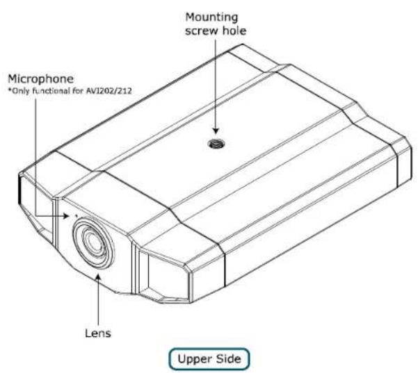

3. INSTALLATION
3.1 Install the Hardware
This camera can be installed in two ways: ceiling-mounted and desktop. During the installation, please make sure the upper side of the camera is always facing up, as shown in Figure 1 below, regardless of which installation way you're using. This is to ensure the video output won't be up side down.
Note: The illustrations below are based on the ceiling-mounted installation.
Note: For the detailed cable connection, please refer to the section "2.1 Rear Panel" at page 3.
Tool needed: Power drill x 1 (not supplied within the sales package)
- Prepare all the parts needed for camera installation.
Find the network camera, bracket package, a bag of screws & wall plugs, and a cap supplied with the sales package, as shown in Figure 1.
Unpack the bracket package to find the bracket disassembled into three parts: the base, stem and joint lock.
Figure 1: Parts needed for camera installation

- Fix the base of the bracket.
Fix the base of the bracket with the supplied 3 screws to the place you want to install by using a power drill.
Figure 2: Screw the base to the ceiling

- Assemble the bracket:
a). Align the stem with the central hole of the base, and rotate it to secure, as shown in Figure 3.
b). Align the joint lock with the stem, and rotate it to secure, as shown in Figure 4.
Figure 3: Connect the stem to the base

Figure 4: Connect the joint lock to the stem

- Connect the camera to the bracket.
Ceiling-mounted:
With the upper side of the camera facing up, align the mounting screw hole on the upper side with the screw thread of the joint lock, and rotate the camera to secure, as shown in Figure 4.
Desktop:
With the upper side of the camera facing up, align the mounting screw hole on the underside with the screw thread of the joint lock, and rotate the camera to secure.
Figure 4: Connect the camera to the bracket

Figure 5: Insert the cap to the camera

- Insert the cap to the other mounting screw hole of the camera.
Ceiling-mounted:
Insert the cap to the mounting screw hole on the underside of the camera, as shown in Figure 5.
Desktop:
Insert the cap to the mounting screw hole on the upper side of the camera.
- Adjust the viewing angle of the camera, and fasten the joint lock to fix the angle. The installation is completed, as shown in Figure 6.
Figure 6: Finish the installation

3.2 Assign an IP address and Access the Camera
Step 1. Install the Software
Place the supplied Video Viewer AP software CD into your DVD- / CD-ROM drive. The installation process will automatically start. Follow the on-screen instructions to install the application programs. After installation, a "Video Viewer" shortcut icon will be shown on your PC desktop.
Step 2. Connect the network camera to the Internet access via a RJ-45 network cable.
Step 3. Search the available IP address to login
a) Double-click “ ” icon on your PC desktop to enter the Video Viewer control panel. By defaults, the “ Address Book” ( ) panel will be displayed on the right side of the Video Viewer control panel.
b) Click "Search" (Search) → "Refresh" (Refresh) to search the available IP address(es). The found address(es) will be listed, and can be added into the address book by clicking "Ad into address book). For details, please see "Search" at page 9.
c) Select the IP address you just added into the address book, and click " (edit) credit the settings. d) Double-click the IP address in the address book to log in.
Note: For detailed network settings under different network types (Static IP / PPPOE / DHCP), please refer to "Network" at page 19 and "DDNS" at page 20.
- If you cannot search any available IP address, please follow the instructions below.
Step 4. Add the IP address and other network settings to login
a) Double-click “” icon on your PC desktop to enter the Video Viewer control panel. By defaults, the “Address Book” panel will be displayed on the right side of the Video Viewer control panel.
b) The default network camera settings are as follows:
| Item | Default Setting |
| IP Address | 192.168.1.10 |
| User Name | admin |
| Password | admin |
| Port Number | 80 |
c) Click "I" (Address Book) → "E" (Add) button to key in the IP address, user name, password, and port number of the network camera you intend to connect.
| Item | Default Setting |
| IP Address | 192.168.1.10 |
| User Name | admin |
| Password | admin |
| Port Number | 80 |
d) Double-click the IP address you just added into the address book to log in.
After setting up the network information, login user name and password, double-click "on the PC desktop to open and log into the Video Viewer control panel. You will see a screen similar to the following with 6 major sections:
| • Connect to only one network camera | • Connect to multiple network cameras (ex. 4 cameras) |
| • 1-cut display [IMAGE] | • 4-cut display [IMAGE] |
 | 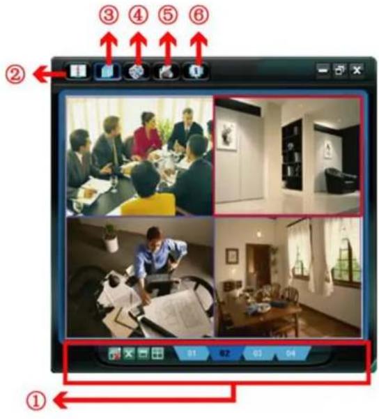 |
| NO. | Button Function Description | ||
| 1 |  | Image Display | To switch to another camera view if two or more network cameras are connected, click the corresponding blue tab. The camera title shown in the blue tab can be customized (For example, “01”, “02”, “03” and “04”). The default camera title “Camera1”. For detailed camera title setting, please refer to “General” at page 16. The software can control up to 16 network cameras simultaneously. |
 | Scale | Click to view the images in the 1-cut, 4-cut, 9-cut and 16-cut mode. | |
 | Full Screen | Click to view the images in the full screen mode. To exit the full screen mode, press “Esc” key on the keyboard of the PC. | |
| [ZX05] | Close | Click to close the current image display view.If the image display view is closed, you will be logged out automatically. | |
| [XW4E] | Close All | Click to close all the current image display view.If the image display view is closed, you will be logged out automatically. | |
| 2 |  | Address Book | Click to show the predefined IP address(es). You can add, remove or search the IP address to log in the network camera remotely. |
| 3 |  | Miscellaneous Control | Click to show the main operation functions: audio volume control, color setting, backup, record setting, server setting, upgrade, and find status log list. |
| 4 |  | Record | Click to start / stop the manual recording. |
| 5 |  | Snapshot | Click to take a snapshot of the current view. The snapshot will be saved in the path you specified in “5.3 Record Setting” at page 14. |
| 6 | [SHD3] | Information Click to show the current network connection details. | |
4.2 Address Book

This view is displayed when the Video Viewer is activated for you to log in / out the network camera from the current address list, or search the available IP address as follows:
Address Book

Search

(Address Book)
Click to view the pre-defined network camera access details.
To log in, choose one IP address from the address list, and click the address twice; to log out, click the connected IP address twice.
You can also create new IP address information, or modify or remove the current IP address information.
| NO. | Button Function | Description | |
| 1 |  | Add | Click to directly add one IP address for login. Key in all the network camera access information needed, and click “Apply” and “Close” to add the selected address to the address book.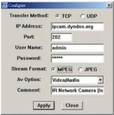 |
| 2 |  | Edit | Select one current IP address from the address list, and click this button to edit the settings. |
| 3 |  | Remove Select one IP address from the address list, and click this button to delete it. | |
| 4 | (437) | Record | Check this checkbox to enable the record settings. For details, please refer to the “5.3 Record Setting” at page 14. The default setting is unchecked. |
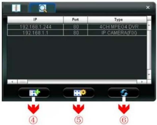
(Search)
Click to search and view the available IP address(es) for the network camera connection. You can choose one address to add into the address book, edit the details, or update the address list.
| NO. | Button Function | Description | |
| 4 |  | Add into address book | Select from the available IP address list, and click this button. Key in the network camera access information needed, and click “Apply” and “Close” to add the selected address to the address book. |
| 5 |  | Setting | Select from the available IP address list, and click this button to edit the setting. |
| 6 |  | Refresh Click to update the available IP address list. | |
4.3 Manual Record
1) Choose the record type and assign the record location
Click “☐” (Miscellaneous Control) → “☐” (Record Setting) to go to the “Record Setting” page. Check the record type “Manual”, and assign the location to save the recordings by double-clicking the “Video Path” cell.

2) Enable the record settings
Once the “Manual” checkbox is checked in the “Record On/Off” section, check the “REC” box in the address book panel “☑” to enable the record settings.

3) Click “ ” (Record) button to start manual recording
Click "Record" (Record) on the main control panel to start the manual recording immediately, and the recordings will be saved in the specified location. When the record function is started, a flashing indication icon will be shown at the bottom right corner of the image display view.
Note: For detailed schedule record setting, motion-triggered and alarm-triggered recording, please refer to "5.3 Record Setting" at page 14, "Trigger" at page 18 and "Detection" at page 25.
4.4 Playback
To play a recording, click “☐” (Miscellaneous Control) > “☐” (Status List), and select the “Record” tab. A list of all the recordings will be shown by defaults, and you can also sort out the logs you want to speed up the search time. For details, please see “5.6 Status List” at page 27.
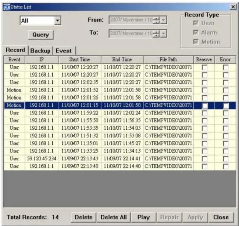
To immediately play a recording file, select a log from the list, and click "Play" button, or double-click the selected log. Then, the playback control panel will be shown at the bottom of the main control panel similar to the following.
For the playback control panel details, please see "Playback Screen" at page 31.

4.5 Snapshot
To take a snapshot of the current view, click “(Snapshot) on the main control panel. Once the current view is captured, you’ll see an icon shown at the bottom right corner of the image display view.
The snapshot will be saved in the path you specified in “Record Setting). For snapshot path setting, please refer to “5.3 Record Setting” at page 14.

4.6 Information

Click this button to show the current network connection details:
1) IP Address 7) Quality
2) Transfer Type 8) Resolution
3) Stream Format 9) Server Time
4) AV Option 10) Online Users
5) Bits Rate
6) Frame Rate
11) Current Disk Capacity

5. VIDEO VIEWER MISCELLANEOUS CONTROL PANEL
Click “Miscellaneous Control) on the Video Viewer control panel, and 7 functions are available as follows:
Click the button ?
to show the software version

| Click the button show the current version of the Video Viewer.The audio / broadcast function is only for DN-16051 models. | |||
| NO. | Button Function | Description | |
| 1 |  | Audio On / Off | Click this button to turn on / off the audio function of the network camera. |
 | Broadcast On / Off | Use the broadcast function from your PC to the connected network cameras. Please make sure the following items are ready before using this function.Your PC is connected to a microphone device and has the Video Viewer software installed.The connected network cameras are connected to speakers.The audio function of the connected network cameras is turned on ( ). | |
 | Audio Volume Control | To adjust the volume of the audio, press and drag the volume slider. | |
| 2 |  | Color Setting | Click this button to adjust the brightness / contrast / hue / saturation for the selected network camera. For details, please see "5.1 Color Setting" at page 13. |
| 3 |  | Backup(For DVR only) | The network cameras don't support network backup function. This function is available when the Video Viewer is connected to a DVR. You can log into the DVR via this software and remotely backup the video data saved in the DVR. For details, please see "5.2 Backup" at page 13. |
| 4 |  | Record Setting | Click this button to go to the detailed record setting. For details, please refer to "5.3 Record Setting" at page 14. |
| 5 |  | Server Setting | Click this button to go into the detailed server setting. For details, please refer to "5.4 Server Setting" at page 14. |
| 6 |  | Tools | Click this button to update the firmware version of your network camera. For details, please refer to "5.5 Tools" at page 25. |
| 7 |  | Status List | Click this button to view all the record list and login/logout event list, search the desired log list(s) by date, or playback the recording of the selected log list. For details, please refer to "5.6 Status List" at page 27 . |
5.1 Color Setting
In the live view page, choose the desired network camera from the image display tab. Click “Miscellaneous Control” → “Color Setting” (Color Setting) to go into the “Color Setting” page, and you can adjust the brightness / contrast / hue / saturation for the selected network camera.

Click “ (Set) to apply the change to the selected network camera. Click “ ” (Before) and click “ ” (Set) to return to the default color settings.

Note: You need to be a supervisor to operate this function. For details, please see "Account" at page 17.
5.2 Backup (For DVR only)
The network cameras don’t have network backup function. This function is available when the Video Viewer is connected to a DVR. You can log into the DVR via this software and remotely backup the video data saved in the DVR. Click “” (Miscellaneous Control) → “” (Backup) to go into the “Backup” page, and you can select a specific time range or event to make a video backup of the recorded files saved in the DVR.
Note: You need to be a supervisor to operate this function. For details, please see "Account" at page 17.

| NO. | Function | Description |
| 1 | IP Address / Port / User Name / Password | Select the IP address of the desired network camera from the drop-down list and check if the network information is correct. |
| 2 | HDD Number / Channel | Specify the hard disk (HDD Number) and channel number (Channel) within which have the video data you need. |
| 3 | Filter the recorded video by time | Specify the time range within which has the video data you want in the “Start Time” and “End Time” columns. |
| 4 | Filter the recorded video by event | Select an event type from the event list. This list shows all logs in the specified network storage device from the latest to the earliest. |
| NO. | Function Description | |
| To quickly find the events you need, check or uncheck the event type “ System” / “ Manual” / “ Alarm” / “ Motion”, and select the log you vTo view the earlier or later logs that are not shown in the current page, click “ Prev. Page” or “ Next Page”.To refresh the event list, click “ Reload”. | ||
| 5 | File Path Assign the location where the backup files are saved. | |
| 6 | Display | To view the backup images simultaneously when the download process is in progress, select the checkbox “ Display”. You will see the backup images while the images are being downloaded to the PC or notebook.To simply backup images without previewing, deselect the checkbox “ Display”. You will only see a message box indicating the total tim needed, the current status and the saving location. |
| 7 | Download / Cancel Click “ Download” to start or “ Cancel” to discard the video backup. | |
5.3 Record Setting
Click “☐” (Miscellaneous Control) → “☐” (Record Setting) to go into the “Record Setting” page, and you can set which type of the recording is enabled (Manual / Schedule / Motion / Alarm), and where the recorded data / snapshots are saved.
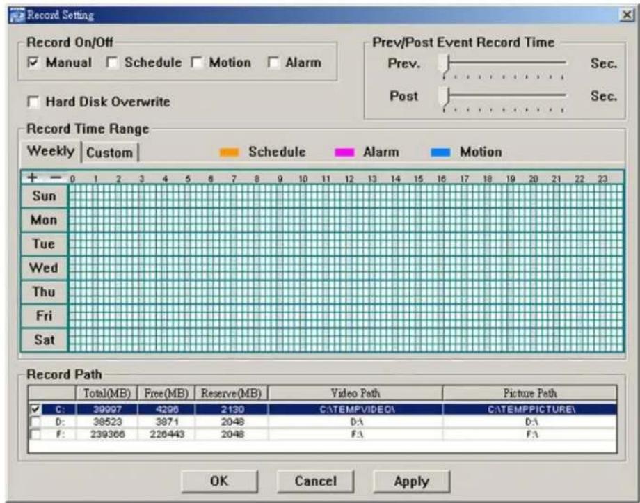
Note: Once all the record settings are finished, please check the "REC" checkbox in the address book panel "✓" to enable the record setting. Please refer to "Address Book" at page 8.

Record On/Off
In this section, you can select which type of the recording will be enabled. There are 4 options: Manual / Schedule / Motion / Alarm.
Prev / Post Event Record Time
In this section, you can set the pre- / post-event record time from 0 \~ 10 seconds by pressing and dragging the slider.
Hard Disk Overwrite
Check this checkbox to overwrite from the oldest recorded data when the HDD is full.
Record Time Range
There are two options available for you to set the recording time: Weekly & Custom.
◆ Weekly
Choose the time box(es) within which you want to enable the recording. The time scale is from 0 \~ 24 hours per day, and there are 3 time lines for each weekday, representing 3 different recording types.
When you select the time box(es), you may see the color orange, pink or blue:
orange => the 1st line, schedule record
pink => the 2nd line, alarm record
blue => the 3rd line, motion record

Tip: To set schedule record, alarm record and motion record all at once for the whole week, press “+” button. To clear all record time settings, press “—” button.
◆ Custom
To specify the more specific time for recording, click "Custom".

a). Select the desired record type(s) (Schedule / Motion / Alarm), and set the start & end date and time.
b). Press "Add", and a pop-up window will appear and ask you to confirm your setting. Click "OK" to add the record setting, or "Cancel" to discard the setting.
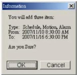
c). After adding the record setting, you will see the item(s) you added in the custom record list.
To delete a certain item, choose the item you want to delete, and click "Delete".
To modify a certain item, choose the item you want to modify, change the start time and end time, and click "Update".

Record Path
Select and view the location for saving the recorded video and snapshot pictures.
To change the saving path for the recorded video clips or snapshots, check the drive you want, click the cell of "Video Path" or "Picture Path" twice, and select a new path for saving the video clips or snapshots.
5.4 Server Setting
Click “☐” (Miscellaneous Control) > “☐” (Server Setting) to go into the “Server Setting” page, and you can view, set or modify all the network camera setting. All the changes you make here will be applied to the connected network camera.
Note: You need to be a supervisor to operate this function. For details, please see "Account" at page 17.
General
Click "☐" (Miscellaneous Control) → "☐" (Server Setting) → "General" to go into the "General" page. In
"General" page, you will see the following items:

| Item | Description |
| Firmware Version | Display the current firmware version of the network camera. |
| MAC Address | Display the MAC address of the network camera. |
| Title | Provide a title for the network camera. Only 15 characters are allowed. The default camera title is “Camera1”. |
Log
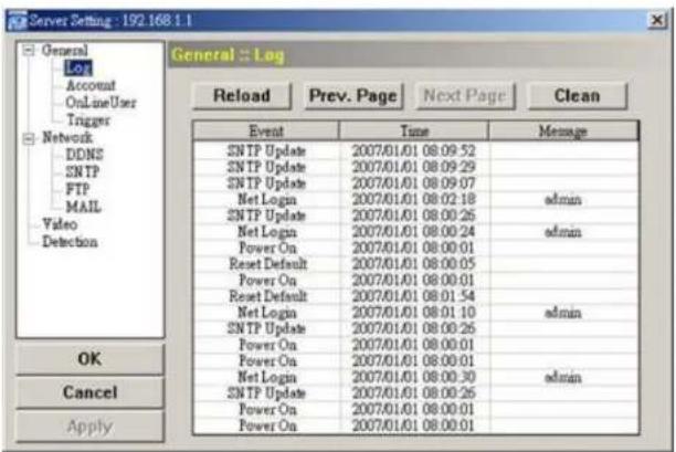
Click “ [icon] ” (Miscellaneous Control) → “ [icon] ” (Server Setting) → “General” → “Log” to go into the “Log” page. In the “ Log” page, you can see all the logs for the network camera, such as “ Power On ”, “ Reset Default ”, “ Net Login ” a “ SNTP Update” ... etc.
- To refresh the logs, click "Reload".
- To view the earlier or later logs that are not shown in the current page, click "Prev. Page" or "Next Page".
- To clear all the logs, click "Clean".
Account
Click “☐” (Miscellaneous Control) → “☐” (Server Setting) → “General” → “Account” to go into the “Account” page. In the “Account” page, you can create a new account for login, or delete or modify the existing account setting.
To add an account, click "New", and set the "User Name", "Password", "User Level" and "Life Time". Then, click "Apply" to save your setting and create a new account.

• To modify an existing account, select the account you want, change the setting, and click "Apply".
• To remove an existing account, select the account you want, and click "Delete".
• To save your changes, click "Apply".
| Column Description | |
| User Name Set a user name that will be used for remote login. The user name allows up to 31 characters. | |
| Password | Set the password that will be used for remote login. The password allows up to 31 characters. |
| User Level | Set the security level of an account to give the permission to control different Video Viewer functions.There are 4 user levels: “Supervisor”, “Power User”, “Normal User” and “Guest”. |
| For the functions each user level is allowed to access, please see the information below: | |
| Supervisor Power User Normal User Guest | |
| Address Book ● ● ● ● | |
| Miscellaneous Control | |
| Color Setting ● X X X | |
| Backup ● X X X | |
| Record Setting ● ● ● ● | |
| Server Setting ● X X X | |
| Tools ● X X X | |
| Status List ● ● ● ● | |
| Record ● ● ● ● | |
| Snapshot ● ● ● ● | |
| Information ● ● ● ● | |
| Life Time Select how long this account is allowed to stay online (1 MIN / 5 MIN / 10 MIN / 1 HOUR / 1 DAY / INFINITE) | |
| Max User(s) Allow maximum 10 online users simultaneously | |
Online User
Click “☐” (Miscellaneous Control) → “☐” (Server Setting) → “General” → “OnLineUser”, and you can check all the online user information. To update the user information, click “Refresh”.

Trigger
Click "☐" (Miscellaneous Control) > "☐" (Server Setting) > "General" > "Trigger" to enter this page.
DN-16050

DN-16051

♦ Motion Trigger:
In this section, you can select to enable the function of motion trigger. Before this function is enabled, you need to set the motion detection area first. For motion detection area setting, please refer to "Detection" at page 25.
| Item Description |
| Motion In this section, you can select to enable the function of motion trigger. |
| Duration Set the duration time of the motion trigger recording (5 / 10 / 20 / 40 seconds). |
◆ Alarm Trigger (Only for DN-16051):
In this section, you can select to enable the function of alarm trigger.
◆ Notify
In this section, you can select to enable the function of E-mail and/or FTP notification.
| Item Description | |
| Method | • Email Notification:If the E-mail notification function is activated, the network camera will send the captured video clip to the assigned E-mail address(s) once motion-trigger or alarm-trigger recording happened.☐~ FTP Notification:If the FTP notification function is activated, the network camera will upload the captured video clip to the specified FTP site once motion-trigger or alarm-trigger recording happened. |
| Video Type Display | the video type of the notification files. The video type will vary according to the setting of “Stream Format” in the “ ” (Address Book) page. |
| Total Set the record | time of the notification video clip (1 ~ 5 seconds). |
Network
Click "☐" (Miscellaneous Control) > "☐" (Server Setting) > "Network" to go into the "Network" page. In "Network" page, you can set the network configuration of the network camera.

Select the network type you will be using for the network camera connection. There are 3 network connection types: Static IP, PPPOE and DHCP.
Note: PPPOE and DHCP network connection types are required to apply the DDNS service to get a "Hostname" to correspond to a dynamic IP address. Please refer to "DDNS" section for details.
| Function | Description |
| Web Port | Typically, the default TCP port used by HTTP is 80. However, in some cases, it is better to change this port numb for added flexibility or security. The valid web port number ranges from 1 to 9999. |
| Static IP | Computers are communicated and recognized by their own unique IP addresses over the Internet. “Static IP” provided by your ISP (Internet Service Provider) means the IP address of the computer is fixed.Key in the server IP address, gateway and network information provided by your ISP provider to configure a static IP network connection. |
| Function Description | |
| PPPOE | PPPOE stands for Point-to-Point Protocol over Ethernet. Users can easily have the Internet service as long as they’ re ready for the following things: 1) Insert an Ethernet card into the PC. 2) Obtain the ADSL service via any ISP. 3) Obtain and install the PPPOE software CD.When everything is ready, choose the “ PPPOE” IP type, and key in the user name and password provided by yISP. Then, select “ Network” > “ DDNS” to set DDNS settings.For detailed DDNS settings, please refer to“ DDNS” section. |
| DHCP | This DHCP function needs to be supported by a router or cable modem network with the DHCP service. Choose the “ DHCP” IP type, and select “ Network” > “ DDNS” to set DDNS settings.For detailed DDNS settings, please refer to“ DDNS” section. |
DDNS
You need to apply a DDNS account before setting PPPOE or DHCP connection. DDNS is a service for transforming the dynamic IP corresponding to a specific “host name”. Go to a website which provide free DDNS services and apply a host name.
Click "☐" (Miscellaneous Control) > "☐" (Server Setting) > "Network" > "DDNS" to enter.

◆ DDNS Apply:
You need to apply a DDNS account before setting PPPoE or DHCP connection. DDNS is a service for transforming the dynamic IP corresponding to a specific "Hostname". Please refer to the steps below.
- Go to a website which provides free DDNS services and apply a "Hostname".
For example, go to http://www.dyndns.com.

• Enter all the information necessary for signing up an account according to the website instructions.


- Then, you will see the screen "Account Created", and Dyndns will email the instructions to your specified E-mail address for enabling your account. You must complete the procedure according to the instructions in the mail. That is to must visit the confirmation address within 48 hours of the time that the e-mail was sent to complete the account creation process. Then, you will see "Account Confirmed". Your account is created successfully now.

- Log in with your account information and click " My Service" .

- Click "Add Host Services".
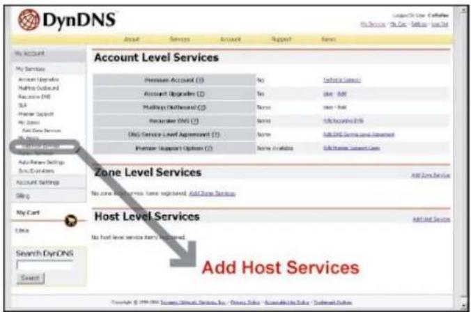
- Click "Add Dynamic DNS Host".

• Fill in and choose the desired host name.

- The host name is created. You will be connected to the corresponding IP address whenever you enter this hostname.

SNTP
SNTP (Simple Network Time Protocol) is for time setting. Click “☐” (Miscellaneous Control) → “☐” (Server Setting) → “Network” → “SNTP” to go into the “SNTP” page.
![Server Setting : 192.168.1.1 General Log Account OnLineUser Trigger Network DDNS SNTP FTP MAIL Video Detection Network :: SNTP GMT: [GMT+08:00] Taipei Server Name: time.stdtime.gov.tw Sync Server Time OK Cancel Apply](/content/2026/05/920133/images/9e62afce402f74da347c21386ebb1716fba41ce095f6d5588632e1694c94b040.jpg)
| Function Description | |
| GMT (Greenwich Mean Time) | Once users choose the time zone, the network camera will adjust the local area time of the system automatically. |
| Server Name Users can simply use the default SNTP server (For example, time.stdtime.gov.tw). | |
| Sync Server Time The network camera will synchronize the time with the network time. | |
FTP
Click "1" (Miscellaneous Control) → "2" (Server Setting) → "Network" → "FTP" to go into the "FTP" page.
Enter the detailed FTP information and press "Apply" to confirm. The information you set here will be applied when the function of FTP notification is enabled in the "Trigger" menu.

Click “☐” (Miscellaneous Control) → “☐” (Server Setting) → “Network” → “MAIL” to go into the “MAIL” page. Enter the detailed E-mail information and press “Apply” to confirm. The information you set here will be applied when the function of E-mail notification is enabled in the "Trigger" menu.

| Function Description | |
| Server Enter the SMTP server | address provided from your e-mail system supplier. |
| Mail From Enter the entire mail | address to ensure E-mails will not be blocked by SMTP. |
| Verify Password Some mail servers are required to verify the password. Please enter the “user name” and “password”. | |
| Email Address | Add the E-mail address(s) of the assigned recipient(s). |
Note: Users can assign up to 4 mail accounts for E-mail notification.
Video
Click "☐" (Miscellaneous Control) > "☐" (Server Setting) > "Video" to go into the "Video" page.

| Item | Description |
| System Type | Select the system type of the connected network camera. |
| MPEG | Image Resolution: VGA (640 × 480) / QVGA (320 × 240)Image Quality: BEST / HIGH / NORMAL / LOW |
| Stream Format | Select the stream format of the network transmission (MPEG-4 / Motion JPEG). |
| Frame Rate | The frame rate allowed to each viewer can be adjusted to adapt to the bandwidth on the network. Set the desired image frequency to the maximum (FULL) or to a specified frame rate (HALF / ONE THIRD / QUARTER / ONE FIFTH / ONE TENTH / ONE FIFTEENTH). |
| Item Description | |
| The actual frame rate depends on the actual network connection, and may be lower than the specified one. | |
| Maximum Exposure Limits To | compensate for the lighting conditions, the maximum exposure time can be adjusted.There are five levels of the exposure control. The shortest exposure time is LEVEL 0, and the longest exposure time is LEVEL 5. This setting will affect the video image quality. |
Detection
Motion detection is used to generate a motion trigger whenever a movement occurs in the video image. Select the desired channel, and click “Edit” to enter the setting page of the motion detection area.
![Server Setting : 192.168.1.1 General Log Account OnLineUser Trigger Network DDNS SNTP FTP MAIL Video Detection Detection OK Cancel Apply [+]Select All [-]Clear All Apply](/content/2026/05/920133/images/ddc551daf3f4eb2060bd73298d0e739298cb128acf31264d8e5c84a343a0750a.jpg)
| Function Description | |
| Motion Detection Setting Area | Set the motion detection area by selecting the area grids with your mouse. Pink grids represent the area that is not being detected while the transparent grids are the area under detection. You can set multiple areas under detection. |
| Select All | Click “+” (Select All) to set the whole area under detection. |
| Clear All Click “-” | (Clear All) to set the whole area undetected. |
| Apply After setup, click “Apply” to confirm. | |
5.5 Tools
Click "☐" (Miscellaneous Control) → "✗" (Tools) to go into the "Tools" page.
Note: You need to be a supervisor to operate this function. For details, please see "Account" at page 17.
Update Firmware
In this page, you can upgrade the firmware version of your network camera.

| Function Description | |
| Update Server Select the IP address of the network camera. Make sure the network settings of the selected network camera are correct. | |
| Current Version In the “ Firmware” section, you will see the current firmware version.For example, 1022-1020-1001 | |
| Add To upgrade the firmware version of your network camera, click “ Add” to locate and select the firmware files.There are several upgrade files. Please upgrade one by one. | |
Update Firmware To start upgrading the firmware of the network camera, click “ Update Firmware” to start the upgrade process. After upgraded, you will see a message shown on the screen:“ Update Firmware Succeeded! Don’t plug off power, the machine will reboot automatically!” | |
| Configure Backup (For DVR only) | If you want to backup your system before upgrading the firmware version, select “ System Backup” in the “ Configure File” section, click “ ... ” to specify the location for saving system backup, and click “ Backup” to start the backup process. |
Note: The network setting of the camera might restore to default values after upgrade. If this is true, please set the network information again.
5.6 Status List
Click “” (Status List) to view all the record list and login/logout event list (All), or search the desired log list(s) by date, or playback the recording of the selected log list (Condition).
There are three types of logs: Record, Event and Backup. To playback the recorded data for a specific record log, select the log, and double-click to start the video playback.
For detailed playback operation, please refer to "Playback Screen" at page 31.
Record List
Select “ All” to show all record logs, or “ Condition” to search for the specific log(s) by date or by record type.
• All

| Button Description | |
| Query Press this button to refresh the log list. | |
| Delete / Delete All | Click “Delete” to remove the selected log(s), or click “Delete All” to clear the current log list.Tip: To select more logs all at once, press and hold the “Ctrl” key on your keyboard, and click to select the logs you want to remove. |
| Play Click to play the selected record log. The playback panel will be shown for your further operation. For playback details, please refer to “Playback Screen” at page 31. | |
| Repair Click to fix the log with errors. | |
| Apply | This button is available in the “Record” tab when the “Reserve” checkbox is checked or unchecked.If you want to keep an important record log for future reference and it can’t be removed, check the “Reserve” checkbox, and click “Apply”. The selected log will be kept and won’t be deleted when somebody accidentally or intentionally chooses it and click “Delete” or “Delete All”. |
| Close | Click “Close” to quit this window. |

| Button / Function Description | |
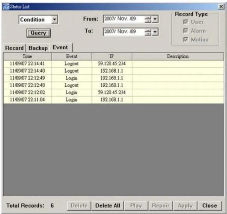
| Date Selection(From / To) | Choose the specific date range including the event / record logs you might want. |
| Record Type This section is enabled only when the “ Record” tab is selected.Select the record type you want to search (User / Alarm / Motion). | |
| Query When all the search criteria are set, click to search the specified logs. The result will be displayed in the log list, arranged by time from the latest to the earliest. | |
| Delete / Delete All Click “ Delete” to remove the selected log(s), or click “ Delete All” to clear the current log list.Tip: To select more logs all at once, press and hold the “Ctrl” key on your keyboard, and click to select the logs you want to remove. | |
| Play Click to play the selected record log. The playback panel will be shown for your further operation. For playback details, please refer to “ Playback Screen” at page 31. | |
| Repair Click to fix the log with errors. | |
| Apply | This button is available in the “ Record” tab when the “ Reserve” checkbox is checked o unchecked.If you want to keep an important record log for future reference and it can’t be removed, check the “ Reserve” checkbox, and click “ Apply” . The selected log will be kept and won’t be delete when somebody accidentally or intentionally chooses it and click “ Delete” or “ Delete All”. |
| Close | Click “ Close” to quit this window. |
Login / Logout Event List
Select "All" to show all event logs (Login / Logout), or "Condition" to search for the specific event log(s) by date.
• All

- Condition
Backup List (For DVR only)
The network cameras don't support network backup function. This function is available when the Video Viewer is connected to a DVR. You can remotely view the backup list and playback the selected item.
Select "All" to show all download logs, or "Condition" to search for the specific log(s) by date.
• All
| Button Description | |
| Query Click this button to refresh the log list. | |
| Delete / Delete All | Click “Delete” to remove the selected log(s), or click “Delete All” to clear the current log list.Tip: To select more logs all at once, press and hold the “Ctrl” key on your keyboard, and click to select the logs you want to remove. |
| Play Click to play the selected record log. The playback panel will be shown for your further operation. For playback details, please see “Playback Screen” at page 29. | |
| Repair Click to fix the log with errors. | |
| Apply | This button is available in the “Record” tab when the “Reserve” checkbox is checked or unchecked.If you want to keep an important record log for future reference and it can’t be removed, check the “Reserve” checkbox, and click “Apply”. The selected log will be kept and won’t be deleted when somebody accidentally or intentionally chooses it and click “Delete” or “Delete All”. |
| Close | Click “Close” to quit this window. |
- Condition
| Button / Function | Description |
| Date Selection(From / To) | Choose the specific date range including the event / record logs you might want. |
| Query | When all the search criteria are set, click to search the specified logs. The result will be displayed in the log list, arranged by time from the latest to the earliest. |
| Delete / Delete All | Click “Delete” to remove the selected log(s), or click “Delete All” to clear the current log list.Tip:To select more logs all at once, press and hold the “Ctrl” key on your keyboard, and click to select the logs you want to remove. |
| Play | Click to play the selected network backup log. The playback panel will be shown for your further operation. For playback details, please see “Playback Screen” at page 31. |
| Repair | If the backup file has error, click this button to fix the log with errors. |
| Apply | This button is available in the “ Backup” tab when the “ Reserve” checkbox is checked or unchecked.If you want to keep an important record log for future reference and it can’t be removed, check the “Reserve” checkbox, and click “Apply”. The selected log will be kept and won’t be deleted when somebody accidentally or intentionally chooses it and click “ Delete” or “ Delete All”. |
| Close | Click “ Close” to quit this window. |
Playback Screen
When you select and play the recorded data for a specific log, you will immediately go into the playback mode, and the following playback panel appears.


| NO. | Function Description | |
| 1 | Playback / Download Info Display | This area shows the detailed playback / download information, such as the file name, record date and time, and the speed, etc. |
| 2 | Playback Progress Bar | This area shows the playback progress and the progress percentage. |
| 3 | Playback Operation | This area is enabled only when the playback is started.(Rewind) / (Forward) / (Stop) / (Pause) / (Play)Rewind / ForwardClick once to get 2X fast rewind / forward, twice to get 4X, three times to get 8X, and four times to get 16X the highest. |
| 4 | De-Interlace Click to reduce the vibration of the paused picture. | |
6. IE WEB BROWSER
6.1 Access the Camera from an IE Web Browser
You can view the images or operate your network camera from an IE web browser.
Note: The supported PC operation systems are Windows 2000 and Windows XP.
Step 1: Key in the IP address used by your network camera in the URL address box, such as “http://ipcam.dyndns.org”, and press Enter. You will be prompted to enter the user name and password to access the network camera. If the port number your network camera used is NOT 80, you need to key in the port number additionally. The format is “http://ipaddress:portnum”.
Take dynamic IP type as an example: Host name "ipcam.dyndns.org" / Port number "DN-16051". Key in "http://ipcam.dyndns.org:DN-16051" into the URL address box, and press "Enter".
Step 2: Enter the user name and password, the same as the ones used at the Video Viewer, and press "OK". You will see a similar screen as the following when the login information is correct.
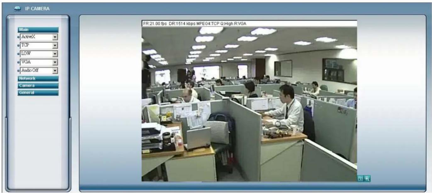
6.2 Toolbar Display on the IE Web Browser
| NO. | Function Description | ||
| 1 | Main | ActiveX / Quick Time | According to the type of web browser on your operating system, choose the ActiveX or QuickTime controls. |
| TCP / UDP | Choose the internet transmission protocol: TCP / UDP. | ||
| BEST / HIGH / NORMAL / LOW | Choose the image quality: BEST / HIGH / NORMAL / LOW | ||
| VGA / QVGA | Choose the image size: VGA (640 × 480) / QVGA (320 × 240). | ||
| Audio On / Audio Off | Choose the audio function: On or Off.(This audio function is only for DN-16051 model) | ||
| 2 | Network | Static IP / DHCP / PPPOE / DDNS | In the “Network” page, you can set the network configuration of the network camera. For details, please refer to “Network” section of the Video Viewer at page 19. |
| SNTP | Set the SNTP (Simple Network Time Protocol) for the time setting. For details, please refer to “SNTP” section of the Video Viewer at page 23. | ||
| FTP | Assigned a specific FTP site for the motion/alarm notification function. For details, please refer to “FTP” section of the Video Viewer at page 23. | ||
| Assigned a specific email account for the motion/alarm notification function. For details, please refer to “MAIL” section of the Video Viewer at page 24. | |||
| NO. Function Description | |||
| 3 Camera | Snapshot Path Set the location where the snapshot pictures are saved. | ||
| Frame Rate | According to the bandwidth, set the required frame rate (FULL / HALF / ONE THIRD / QUARTER / ONE FIFTH / ONE TENTH / ONE FIFTEENTH). For details, please refer to "Video" section of the Video Viewer at page 24. | ||
| System Type Set the system type of the connected network camera (NTSC / PAL). | |||
| Stream Format Select the stream format of the network transmission (MPEG-4 / Motion JPEG). | |||
| Maximum Exposure Limits | To compensate for the lighting conditions, the maximum exposure time can be adjusted. For details, please refer to "Video" section of the Video Viewer at page 24. | ||
| Detection | Motion detection is used to generate a motion trigger whenever a movement occurs in the video image. Set the motion detection area. For details, please refer to "Detection" section of the Video Viewer at page 25. | ||
| Motion Sensitivity Level | Set different motion sensitivity level according to different application. For details, please refer to "Detection" section of the Video Viewer at page 25. | ||
| Color Setting | Adjust the brightness / contrast / hue / saturation for the network camera. For details, please refer to "5.1 Color Setting" section of the Video Viewer at page 13. | ||
| 5 General | Language | Support English / Chinese language for the web interface. | |
| Mac Address | Display the MAC address of the network camera.For details, please refer to "General" section of the Video Viewer at page 16. | ||
| Log | In the "Log" page, you can see all the logs for the network camera, such as "POWER ON", "REMOTE LOGIN", "RESET DEFAULT", "EMAIL", "FTP", "DDNS", "PPPOE", "DHCP" and "SNTP UPDATE"... etc. For details, please refer to "Log" section of the Video Viewer at page 17. | ||
| Account | Add / Edit / Delete the user name, password, user level and life time for accessing the network camera. For details, please refer to "Account" section of the Video Viewer at page 17. | ||
| Trigger | Set the motion trigger and/or alarm trigger function, such as "Trigger Motion", "Trigger Alarm" and "Trigger Duration". Set the motion trigger and/or alarm trigger notification function, such as "Method" and "Record Time". For details, please refer to "Trigger" section of the Video Viewer at page 18. | ||
| Configure | Display and upgrade the firmware version of the network camera. For details, please refer to "5.5 Tools" section of the Video Viewer at page 25. | ||
| 6 | Snapshot | [ZWAT] | Click this button to take a snapshot of the current view. The snapshot will be saved in the path you specified in the "Snapshot Path" of the "Camera" menu from the IE browser. |
| 7 | QVGA Resize | [HKS3] | Click this button to enlarge the QVGA viewing size in the live view. |
7. QUICKTIME PLAYER
You can also use the QuickTime player to log into the network camera and check the live view only.
Note: QuickTime is Apple's multimedia software. You need to have QuickTime installed in you computer first, and you can access the network camera to see the live view.
Step 1: Go to Apple's official website to download QuickTime. The website address is as follows: http://www.apple.com/quicktime/win.html
a). Click "Download" to go into the download page, and select to download the free player.
b). Leave your Email address, and press "Free Download Now" to download the latest QuickTime player.
c). When the download is completed, execute the "QuickTimeInstaller.exe" file, and follow the on-screen instructions to finish the installation procedure.
Step 2: Open your QuickTime player. Select "File" → "Open URL", and key in the URL address.
The URL format is "rtsp://ipaddress/live/mpeg4"
For example, if the IP adderss is "avtechipcam.dyndns.org" and port number is "201", key in "rtsp://avtechipcam.dyndns.org:201/live/mpeg4" in the URL box. Click "OK" to continue.


Step 3: A pop-up window will appear and prompt you to enter the authentication information. Key in the user name and password for accessing your network camera. The user name and password are the same as the ones you use to log into the Video Viewer.
If the information is correct, press "OK" to go on. If not, press "Cancel" to quit the accessing.

Step 4: When the login is successful, you will see a similar screen as the following.

APPENDIX 1 DEFAULT VALUE
- Default Value
| Items Default Value | |
| • Default Network Settings: | |
| User Name admin | |
| Password admin | |
| Port 80 | |
| IP Address 192.168.1.10 | |


- USER'S MANUAL
- CAUTION
- DISCLAIMER
- MPEG4 LICENSING
- VERSION
- PRODUCT OVERVIEW....1
- HARDWARE OVERVIEW .... 3
- INSTALLATION .... 4
- VIDEO VIEWER BASIC OPERATION....7
- VIDEO VIEWER MISCELLANEOUS CONTROL PANEL....12
- IE WEB BROWSER 32
- QUICKTIME PLAYER 34
- APPENDIX 1 DEFAULT VALUE....35
- PRODUCT OVERVIEW
- 1.1 DESCRIPTION
- 1.2 FEATURES
- 1.3 PACKAGE CONTENTS
- 1.4 SPECIFICATIONS
- HARDWARE OVERVIEW
- 2.1 REAR PANEL
- 2.2 UPPER SIDE & UNDERSIDE
- INSTALLATION
- 3.1 INSTALL THE HARDWARE
- 3.2 ASSIGN AN IP ADDRESS AND ACCESS THE CAMERA
- STEP 1. INSTALL THE SOFTWARE
- STEP 2. CONNECT THE NETWORK CAMERA TO THE INTERNET ACCESS VIA A RJ-45 NETWORK CABLE
- STEP 3. SEARCH THE AVAILABLE IP ADDRESS TO LOGIN
- STEP 4. ADD THE IP ADDRESS AND OTHER NETWORK SETTINGS TO LOGIN
- 4.2 ADDRESS BOOK
- (SEARCH)
- 4.3 MANUAL RECORD
- 4.4 PLAYBACK
- 4.5 SNAPSHOT
- 4.6 INFORMATION
- VIDEO VIEWER MISCELLANEOUS CONTROL PANEL
- 5.1 COLOR SETTING
- 5.2 BACKUP (FOR DVR ONLY)
- 5.3 RECORD SETTING
- RECORD ON/OFF
- PREV / POST EVENT RECORD TIME
- HARD DISK OVERWRITE
- RECORD TIME RANGE
- ◆ WEEKLY
- ◆ CUSTOM
- RECORD PATH
- 5.4 SERVER SETTING
- GENERAL
- LOG
- ACCOUNT
- ONLINE USER
- TRIGGER
- NETWORK
- DDNS
- ◆ DDNS APPLY
- SNTP
- FTP
- VIDEO
- DETECTION
- 5.5 TOOLS
- UPDATE FIRMWARE
- 5.6 STATUS LIST
- RECORD LIST
- LOGIN / LOGOUT EVENT LIST
- BACKUP LIST (FOR DVR ONLY)
- PLAYBACK SCREEN
- IE WEB BROWSER
- 6.1 ACCESS THE CAMERA FROM AN IE WEB BROWSER
- 6.2 TOOLBAR DISPLAY ON THE IE WEB BROWSER
- QUICKTIME PLAYER
- APPENDIX 1 DEFAULT VALUE
Brand : Digitus
Model : DN-16050
Category : Security Camera