
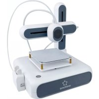
Pro 10+ - 3D Printer Renkforce - Free user manual and instructions
Find the device manual for free Pro 10+ Renkforce in PDF.


| Product Type | FDM 3D Printer |
| Build Volume | 300 x 300 x 300 mm |
| Filament Diameter | 1.75 mm |
| Printing Technology | Fused Deposition Modeling (FDM) |
| Layer Resolution | 0.1 - 0.4 mm |
| Extruder Type | Single Bowden |
| Max Nozzle Temperature | 260 °C |
| Max Heated Bed Temperature | 100 °C |
| Print Speed | 20 - 150 mm/s |
| Supported Filaments | PLA, ABS, PETG, TPU |
| Connectivity | USB, SD Card |
| Display | 4.3-inch Touchscreen |
| Leveling | Manual (4-point) |
| Frame | Aluminum Extrusion |
| Dimensions (W x D x H) | 480 x 480 x 550 mm |
| Weight | 12 kg |
| Power Supply | 24V DC, 360W |
| Operating Voltage | AC 100-240V, 50/60Hz |
| Safety Features | Thermal Runaway Protection, Overheat Protection |
| Maintenance | Clean nozzle, lubricate rods, check belts |
| Spare Parts Availability | Nozzles, hotend, build plate, belts, fans |
| Repairability | Modular design, easy part replacement |
| Included Accessories | Filament sample, SD card, USB cable, tools |
Frequently Asked Questions - Pro 10+ Renkforce
User questions about Pro 10+ Renkforce
0 question about this device. Answer the ones you know or ask your own.
Ask a new question about this device
Download the instructions for your 3D Printer in PDF format for free! Find your manual Pro 10+ - Renkforce and take your electronic device back in hand. On this page are published all the documents necessary for the use of your device. Pro 10+ by Renkforce.
USER MANUAL Pro 10+ Renkforce
GB Operating Instructions
3D Printer Pro 10+
Item No. 2987278

natural_image
Industrial robotic arm in a factory setting, no visible text or symbols on the machinery or background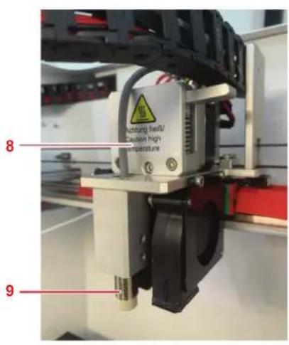
natural_image
Interior view of a mechanical testing setup with labeled components (1 and 2), no readable text or symbols beyond labels8 Touchscreen-Menüs


8.2.1 Not-Halt

natural_image
Hand holding a black cylindrical object against a plain white background (no text or symbols visible)
natural_image
Circular black spool with a small label, no visible text or symbols on the object itself.natural_image
Hand holding a small vial with blue cap, pointing downward (no text or symbols visible)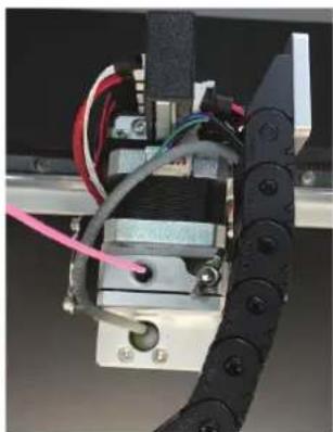
natural_image
Close-up of a mechanical assembly with wires and components, no visible text or symbolsnatural_image
Close-up of a hand operating a sewing machine with red clamps (no visible text or symbols)
natural_image
Industrial machine setup with a black platform and mechanical components (no visible text or symbols)
flowchart
graph TD
    A["52/52"] --> B["28/0"]
    C["1"] --> B
    D["Start"] --> A
    E["Start"] --> B


natural_image
Grid of evenly spaced black dots on a light gray background, no text or symbols presentnatural_image
Close-up of a hand operating a mechanical device with red components, no visible text or symbolsnatural_image
Industrial machine setup with a black frame and metal components, no visible text or symbols

natural_image
Close-up of a mechanical device with a metallic component and a black textured surface (no visible text or symbols)natural_image
Grid of black dots on a gray background, no text or symbols present11.1.3 Manuelles Nivellieren des Druckbetts
natural_image
Close-up of hands operating a mechanical device with a red component, no visible text or symbolsnatural_image
Laboratory setup with mechanical components and a ruler, no visible text or symbols
natural_image
Close-up of a 3D printer in operation with visible mechanical components and a close-up of a fabric or material (no text or symbols)

natural_image
Close-up of a red mechanical device with a circular highlight on its side, mounted on a frame (no visible text or symbols)natural_image
Hand holding a small object near a wall-mounted device (no visible text or symbols)natural_image
Close-up of a 3D printer nozzle dispensing blue liquid into a mechanical component (no visible text or symbols)12 Drucken
natural_image
3D printer in operation with a green plastic cup on a base (no visible text or symbols)
natural_image
Close-up of a hand operating a 3D printer with a green plastic cup on its surface (no visible text or symbols)natural_image
Hand holding a small white object near a wall-mounted device (no visible text or symbols)natural_image
Close-up of a 3D printer nozzle dispensing blue liquid into a mechanical component (no visible text or symbols)

natural_image
Close-up of hands assembling a mechanical component with red circles highlighting specific parts (no visible text or symbols)Abb. 1
16 Wartung
natural_image
Close-up of a hand holding a mechanical component with a magnified inset showing a 3D-printed component (no text or symbols visible)Abb. 2 Abb. 3

natural_image
Close-up of a hand holding a 3D printer with a red circle highlighting the component (no visible text or symbols)natural_image
Close-up of a black electrical outlet switch with red indicator lights and a screwdriver inserted (no visible text or symbols)Abb. 4
17 Aufbewahrung
EN IEC 62368-1:2020 + A11:2020
www.conrad.com/downloads
2 Introduction....37
3 Operating Instructions for download....37
4 Intended use....37
5 Delivery content....38
6 Description of symbols....38
7.1 Printer 39
7.2 Print head 40
7.3 Print bed 41
8 Touch screen menus....42
8.1 System menu....42
8.2 Tools menu 42
8.3 Print menu 44
9 Installation....46
10 Power supply 47
10.1 Connecting to power....47
10.2 Switching on/off 47
11 Before printing 47
11.1 Calibrating the print bed....47
11.2 Loading filament....53
12 Printing....54
12.1 Using Cura....54
12.2 Printing from USB memory stick....54
12.3 Printing from computer via USB cable....54
12.4 Printing from computer via Wi-Fi connection....54
12.5 Removing printed models....54
12.6 Replacing filaments 55
13 Setting up Wi-Fi printing 56
13.1 Using the Wi-Fi configurator software....56
13.2 Setting up Wi-Fi direct mode (computer-to-printer) 57
13.3 Setting up Wi-Fi indirect mode (computer-to-many printers) 59
14 Setting up Cura....61
14.1 Installing Cura on Windows ^® 61
14.2 Installing the Windows ^® driver 61
14.3 Installing Cura on MacOS....61
14.4 Configuring Cura for the Pro 10+....61
15 Cleaning....62
15.1 Cleaning the printer 62
15.2 Cleaning the magnetic mat....62
15.3 Cleaning the nozzle 62
15.4 Cleaning the inside of the nozzle....62
15.5 Cleaning the extruder 63
16 Maintenance....63
16.1 Calibrating the Z-sensor 63
16.2 Replacing the fuse....64
17 Storage 64
18 Troubleshooting....65
19 Disposal....66
20 Declaration of Conformity (DOC)....66
21 Technical data....67
21.1 Power supply 67
21.2 Printing....67
21.3 Software....67
21.4 Wi-Fi module....67
21.5 Environment....67
21.6 Others 67
2 Introduction
Dear customer,
Thank you for purchasing this product.
If there are any technical questions, please contact: www.conrad.com/contact
3 Operating Instructions for download
Use the link www.conrad.com/downloads (alternatively scan the QR code) to download the complete operating instructions (or new/current versions if available). Follow the instructions on the web page.

4 Intended use
The product is a 3D printer.
The product is not designed for use in the food and medical industries.
The product is intended for indoor use only. Do not use it outdoors. Contact with moisture must be avoided under all circumstances.
If you use the product for purposes other than those described, the product may be damaged. Improper use can result in short circuits, fires, electric shocks or other hazards.
The product complies with the statutory national and European requirements. For safety and approval purposes, you must not rebuild and/or modify the product.
Read the operating instructions carefully and store them in a safe place. Make this product available to third parties only together with the operating instructions.
All company names and product names are trademarks of their respective owners. All rights reserved.
5 Delivery content
Printer
Housing
Magnetic mat
Spool holder
Filament tube
Ejector rod
Mains cable
USB memory stick
USB cable
Z-sensor calibration tool
Hex wrench
Pair of tweezers
Side cutter
2x Small needle
4x Hex key (1.5mm / 2mm / 2.5mm / 3mm)
Safety instructions
Quick start guide
Operating instructions
■ Housing assembly instructions
6 Description of symbols
The following symbols are on the product/appliance or are used in the text:

For safe and proper use, follow these instructions. Keep them for future reference.

The symbol warns of hazards that can lead to personal injury.

The symbol warns of dangerous voltage that can lead to personal injury by electric shock.

The symbol warns of hot surfaces that can result in severe burns when touched. Read the information carefully.

The symbol warns of rotating gears that can pull in fingers and hair.

The symbol warns of closing mechanical parts that can trap hands and fingers.

This product must only be used in dry, enclosed indoor areas. It must not become damp or wet.
7 Operating elements
7.1 Printer
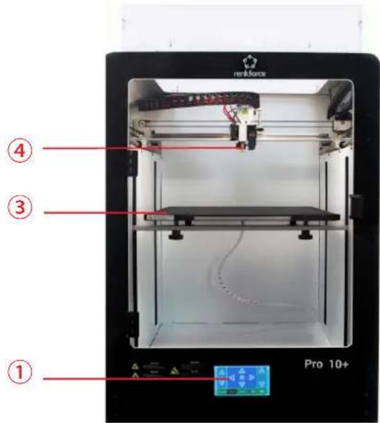

1 Touch screen
2 USB-B port
3 Print bed
4 Print head
5 Cooling fan
6 Power inlet with power switch
7 USB-A port
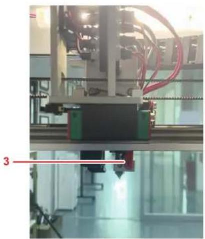
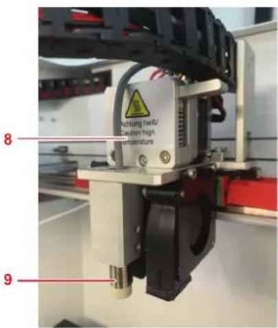
7.2 Print head

1 Nozzle
2 Heat block of hotend
3 Heater and NTC
4 Filament feed tube
5 Heatsink
natural_image
Industrial machine in a cleanroom environment with red wiring and green components (no visible text or symbols)6 Extruder fan
7 Object fan
8 Cover of extruder
9 Automatic leveling sensor
7.3 Print bed

1 Print bed
2 Magnetic mat
3 Leveling screw
4 Heating panel

8 Touch screen menus


The touch screen is on when the power supply is connected. Do not touch the screen with sharp objects.
8.1 System menu

In the menu System you can view information about the printer system settings.
8.2 Tools menu

In the menu Tools you can make parameter adjustments and control the printer.
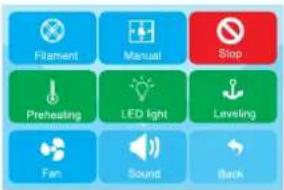
8.2.1 Emergency stop

Touch the button Stop to switch all motors off.
8.2.2 Manual interface

In the menu Manual you can manually steer the print head along the X, Y, and Z-axis.
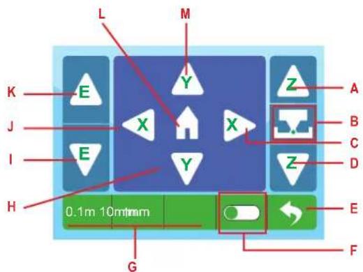
A Move print bed up
B Calibrate Z-offset
C Move to right on X-axis
D Move print bed down
E Return to previous menu item
F Toggle Z-offset on and off
G Select distance increment
H Move print bed foward on Y-axis
I Load filament
J Move to left on X-axis
K Unload filament
L Move print head into zero position
M Move print bed backward on Y-axis
8.2.3 Preheating
In the menu Preheat you can set print bed and extruder temperatures.

flowchart
graph TD
    G --> BedTemp["Bed Temp"]
    F --> BedTemp
    E --> BedTemp
    D --> BedTemp
    BedTemp --> 270["27/0"]
    270 --> 280["28/0"]
    280 --> Exhaluser["Exhalizer"]
    Exhaluser --> 270
    270 --> H["H"]
    270 --> A["A"]
    270 --> B["B"]
    280 --> C["C"]
    280 --> Back["Back"]
A Target temperature
B Increase temperature
C Return to previous menu item
D Extruder temperature
E Print bed temperature
F Decrease temperature
G Current temperature
H Touch to start heating
8.2.4 Filament

In the menu Filament you can control the loading and unloading of filaments.
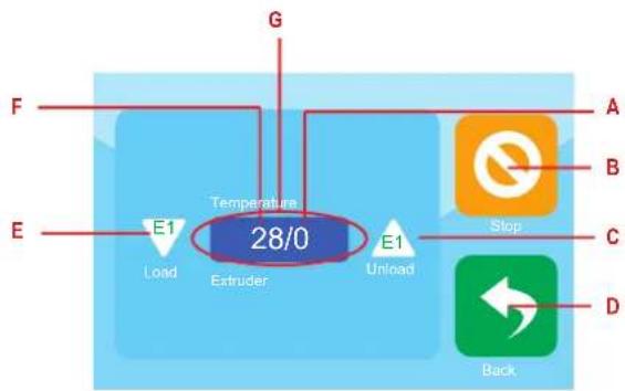
flowchart
graph TD
    F --> Temperature["Temperature"]
    E --> Temperature
    E1 --> Load["Load"]
    E --> Extruder["Extruder"]
    Extruder --> Load
    Extruder --> Unload["Unload"]
    Unload --> Stop["Stop"]
    Stop --> A
    Stop --> B
    Stop --> C
    Stop --> D
    G --> Temperature
    E1 --> Temperature
    28/0 --> Temperature
    style Temperature fill:#666,stroke:#333
A Target temperature
B Stop loading/unloading of filament
C Unload filament
D Return to previous menu item
E Load filament
F Current temperature display
G Touch to start heating
8.2.5 Fan control

In the menu Fan you can adjust fan parameters.

flowchart
graph TD
    A["Extruder fan in %"] --> B["Object fan in %"]
    B --> C["Extruder fan in %"]
    D["F"] --> E["E1(%)"]
    F["E"] --> G["B(%)"]
    style A fill:#4CAF50,stroke:#333
    style B fill:#2196F3,stroke:#333
    style C fill:#2196F3,stroke:#333
    style D fill:#FFA500,stroke:#333
    style E fill:#FFA500,stroke:#333
    style F fill:#FFA500,stroke:#333
    style G fill:#FFA500,stroke:#333
A Decrease air flow
B Touch to switch fan on and off
C Increase air flow
D Return to previous menu item
E Object fan display
F Extruder fan display
8.3 Print menu
In the menu Print you select print files for printing.
8.3.1 Print file selection

flowchart
graph TD
    A["—System Volume Information"] --> B["Body-MINI package"]
    B --> C["Body-MINI+package"]
    C --> D["—N"]
    style A fill:#f9f,stroke:#333
    style B fill:#bbf,stroke:#333
    style C fill:#bfb,stroke:#333
    style D fill:#ffb,stroke:#333
A Navigate menu
B Return to previous menu item
C Print files
8.3.2 Print control

A Stop printing
B Print speed
C Pause printing
D Remaining time
E Adjust print parameters
F Elapsed time
G Print bed temperature
H Nozzle temperature
I Print job progress bar
8.3.3 Print parameters
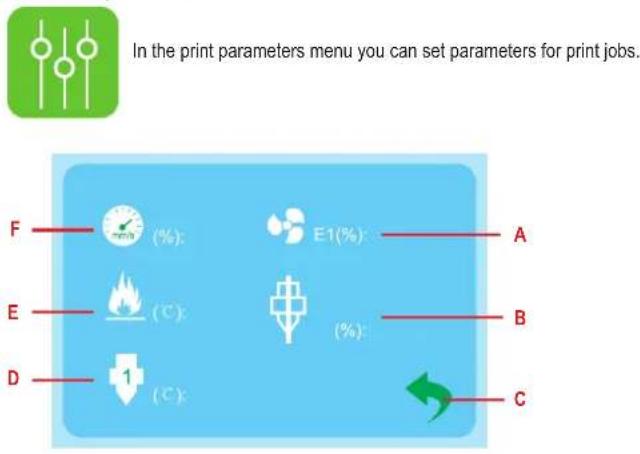
A Set object fan parameters
B Set flow compensation
C Return to previous menu item
D Set nozzle temperature
E Set print bed temperature
F Set print speed
9 Installation
9.3.1 Installing the spool holder

natural_image
Hand holding a black circular object against a plain white background (no text or symbols visible)
natural_image
Circular black spool with a hole, no visible text or symbols on the body9.3.2 Installing the filament tube

natural_image
Hand holding a small vial with a blue cap, pointing downward (no text or symbols visible)
natural_image
Close-up of a mechanical assembly with wires and components, no visible text or symbols- Insert the filament tube in the feeder.
- Insert the filament tube into the extruder.
10 Power supply
10.1 Connecting to power
- Connect the mains cable to the power inlet on the printer.
- Connect the mains cable to a suitable mains outlet.
10.2 Switching on/off
- Flip the power switch into the position I to switch on.
→ The power control light of the switch lights up.
- Flip the power switch into the position 0 to switch off.
Note:
Switch the printer off after use to prevent accidental starting.
11 Before printing
Before you can print you must
calibrate the print bed
load the filament
11.1 Calibrating the print bed
Calibrate the print bed before you use the printer for the first time, after transporting the printer, and whenever you get poor print results that you suspect are related to an incorrectly levelled print bed.
Three calibration procedures can be applied to the print bed.
Automated print bed levelling – “Auto-levelling”
Use "Auto-levelling" to level the print bed automatically. "Auto-levelling" will attempt to level the print bed with high precision and is only useful for making fine adjustments to the print bed.
Z-offset calibration
By calibrating the Z-offset you set the distance between the nozzle and the print bed. Z-offset calibration is followed by "Auto-levelling".
Manual print bed levelling
You level the print bed manually to prepare it for "Auto-levelling". Manual levelling must always be followed by Z-offset calibration and "Auto-levelling".
11.1.1 Using "Auto-levelling" to level the print bed
Use "Auto-levelling" to level the print bed automatically.
"Auto-levelling" will attempt to level the print bed with high precision and is only useful for making fine adjustments to the print bed.
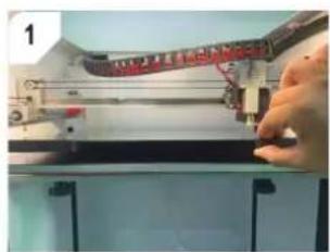
natural_image
Close-up of a hand operating a mechanical device with red components, no visible text or symbolsInsert the print bed and magnetic mat.

natural_image
Industrial machine setup with a red banner mounted on top, no visible text or symbols
flowchart
graph TD
    A["52/52"] --> B["28/0"]
    C["1"] --> B
    D["Fire Icon"] --> A
    E["Arrow Down"] --> B
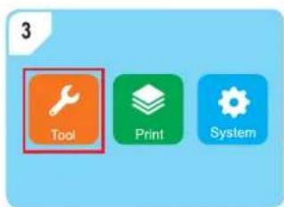
Open the menu Tools.

Touch the button Preheating to start the preheating process.
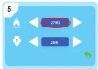
Wait until the preheat temperature has been reached. Touch button Leveling to start "Auto-levelling".

levelling".

natural_image
Grid of black dots on a light gray background, no text or symbols presentWait for "Auto-levelling" to finish.
11.1.2 Calibrating the Z-offset
By calibrating the Z-offset you set the distance between the nozzle and the print bed. Z-offset calibration is followed by "Auto-levelling".

CAUTION
Hot print bed
Touching hot print bed can cause burns
- ● Let cool down before touching
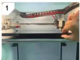
natural_image
Close-up of a hand operating a mechanical device with a red component, no visible text or symbolsInsert the print bed and magnetic mat.

natural_image
Industrial machine setup with a curved conveyor belt and control panel (no visible text or symbols)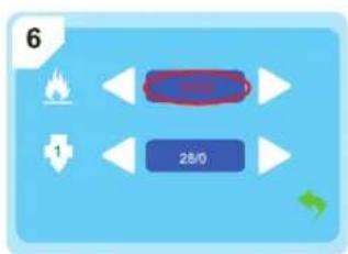
flowchart
graph TD
    A["1"] --> B["2B/0"]
    C["6"] --> B
    B --> D["Output"]
    style B fill:#4CAF50,stroke:#333
    style D fill:#FFA500,stroke:#333

Open the menu Tools.
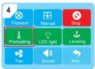
Touch the button Preheating to start the preheating process.

flowchart
graph TD
    A["27/52"] --> B["28/0"]
    C["1"] --> B
    D["Fire Icon"] --> A
    E["Arrow"] --> B
Wait until the preheat temperature has been reached. Open the menu Manual.
flowchart
graph TD
    A["1"] --> B["Control Box"]
    C["6"] --> B
    B --> D["Output"]
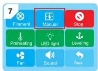

Touch no move the extruder to its zero position.

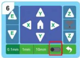
Activate the Z-offset calibration with the slider.

Touch the distance increment 0.1 mm to activate it.

natural_image
Close-up of a 3D printer or scanner with visible mechanical components and no readable text or symbolsSlide one sheet of A4 paper (80 g) between the nozzle and the print bed.
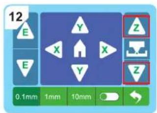
Slide the paper back and forth while repeatedly touching the button to lift or lower the print bed. If you notice slight resistance between nozzle, paper, and print bed, touch the button to finish the calibration.
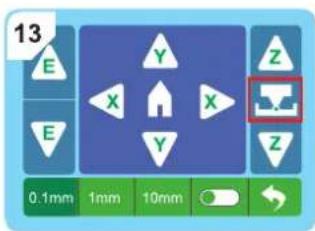
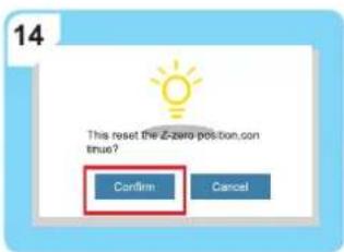
Confirm the Z-offset calibration. Touch the button Leveling to start "Auto-levelling".


natural_image
Grid of black dots on a light gray background, no text or symbols presentWait for "Auto-levelling" to finish.
11.1.3 Levelling the print bed manually
You level the print bed manually to prepare it for "Auto-levelling". Manual levelling must always be followed by Z-offset calibration and "Auto-levelling".
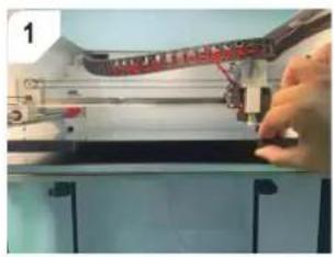
natural_image
Close-up of a hand operating a mechanical device with a red component, no visible text or symbolsInsert the print bed and magnetic mat.
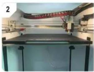
natural_image
Industrial machine setup with a curved pipe mounted on top, no visible text or symbols
Open the menu Tools.

Open the menu Manual.

Touch ▲o move the extruder to its zero position.
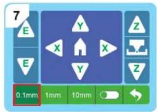
Activate the Z-offset calibration. Touch the distance increment 0.1 mm to activate it.

natural_image
Close-up of a 3D printer or scanner with visible mechanical components and no readable text or symbolsSlide one sheet of A4 paper (80 g) between the nozzle and the print bed.


natural_image
Close-up of a red electronic device with a circular lens and metallic frame (no visible text or symbols)Slide the paper back and forth while repeatedly touching the button ⚠ lift the print bed up. As soon as you notice slight resistance between nozzle, paper, and print bed touch the button Stop interrupt.
Level each of the four indicated calibration points individually.
Touch the buttons ✗ to navigate the extruder to each calibration point.
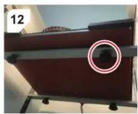
For each calibration point, slide the paper back and forth while turning the calibration screw under the print bed. Stop turning the screw as soon as you notice slight resistance between nozzle, paper, and print bed.
After calibration
After you have calibrated each of the 4 calibration points:
- Calibrate the Z-offset. Follow the instructions in [▶ 11.1.2 Calibrating the Z-offset].
- Level the print bed using "Auto-levelling". Follow the instructions in [▶ 11.1.1 Using "Auto-levelling" to level the print bed].
11.2 Loading filament

Open the menu Tools.

Open the menu Filament.

Touch the temperature display to preheat the extruder.
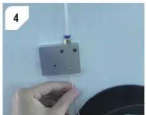
natural_image
Hand holding a small white object above a square wall, with a blue cap on the wall (no visible text or symbols)Cut the filament at an angle and then feed it into the feeder.
flowchart
graph TD
    A["Load"] --> B["Temperature 28/0"]
    B --> C["Unload"]
    C --> D["Stop"]
    C --> E["Back"]
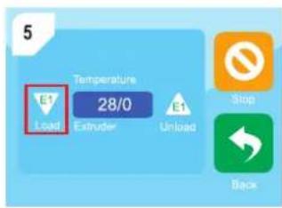
Touch the button E1 Load to load the filament into the extruder.

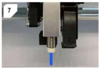
Touch the button Stop as soon as molten filament flows from the nozzle.
natural_image
Close-up of a 3D printer nozzle dispensing blue liquid into a mechanical component (no visible text or symbols)12 Printing
12.1 Using Cura
Cura is an open-source slicing software compatible with the Pro 10+.
If you want to print with Cura, follow to the setup instructions in [▶ 14 Setting up Cura].
12.2 Printing from USB memory stick
- Save the print file that contains the model to the supplied USB memory stick.
- Connect the USB memory stick to the USB-A port on the printer.
- Select the print file from the print menu.
- Print the file.
→ The printer will sound an alarm after printing is complete.
- After printing is complete, flip the power switch into the position 0.
- Let the printer cool down to room temperature.
12.3 Printing from computer via USB cable
After connecting the computer to the printer via USB cable, you can print 3D models directly from the slicing software (example: Ultimate Cura).
- Connect the USB cable to the USB-B port on the printer.
- Connect the USB cable to a USB port on the computer.
- Start the print job in the slicing software.
→ The printer will sound an alarm after printing is complete.
- After printing is complete, flip the power switch into the position 0.
- Let the printer cool down to room temperature.
12.4 Printing from computer via Wi-Fi connection
After connecting the computer and the printer via Wi-Fi, you can print 3D models directly from the slicing software (example: Ultimate Cura).
- Set up and configure Wi-Fi by following the Wi-Fi setup instructions in [▶ 13 Setting up Wi-Fi printing].
- Start the print job in the slicing software and wait for it to complete.
→ The printer will sound an alarm after printing is complete.
- After printing is complete, flip the power switch into the position 0.
- Let the printer cool down to room temperature.
12.5 Removing printed models

CAUTION
Hot print bed
Touching hot print bed can cause burns
● ● Let cool down before touching
- Flip the power switch into the position 0.
- Let the printer cool down to room temperature.
- Remove the magnetic mat with the printed object.

natural_image
3D printer in operation with a green plastic cup on a base (no visible text or symbols)
natural_image
Close-up of a 3D printer in operation with a green component on a black base, no visible text or symbols12.6 Replacing filaments
If you want to use a different filament, you must first unload the current filament and then load the new filament.

Open the menu Tools.

Open the menu Filament.
flowchart
graph TD
    A["Load"] --> B["Temperature 28/0"]
    B --> C["Extruder"]
    C --> D["Stop"]
    D --> E["Back"]
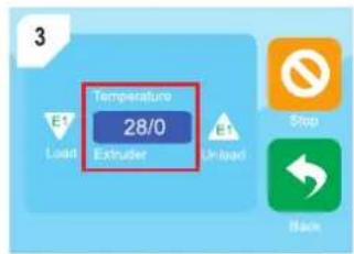
Touch the temperature display to preheat the extruder.

flowchart
graph TD
    A["Load"] --> B["Temperature 28/0"]
    B --> C["Extruder"]
    C --> D["Unload"]
    D --> E["Stop"]
    D --> F["Back"]
Touch the button E1 Unload to unload the current filament.
natural_image
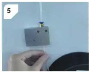
Hand holding a small object near a wall-mounted device (no visible text or symbols)Touch the button Stop as soon as the current filament has been completely retracted from the feeder.

Touch the button E1 Load to load the filament into the extruder.

Touch the button Stop as soon as molten filament flows from the nozzle.

natural_image
Close-up of a 3D printer nozzle dispensing blue liquid into a white plastic component (no text or symbols visible)13 Setting up Wi-Fi printing
For Wi-Fi printing, you can set up two different modes: direct (computer-to-printer) and indirect mode (computer-to-many printers). To set up and control Wi-Fi connections you make use of the Wi-Fi configurator software.
Direct mode (computer-to-printer)
In direct mode, the printer establishes an ad-hoc Wi-Fi network to which you connect the computer.
You use the Wi-Fi configurator software to configure the connection and send print jobs to the printer.

Indirect mode (computer-to-many printers)
In indirect mode, printers and the computer communicate via a Wi-Fi network (example: home Wi-Fi network). You can connect multiple printers to the Wi-Fi network and control them all via the Wi-Fi configurator software.
You use the Wi-Fi configurator software to configure the connections and send print jobs to the printers.

13.1 Using the Wi-Fi configurator software
Note:
The Wi-Fi configurator software is only available for Windows ^® .
To control Wi-Fi connections to printers, you must use the Wi-Fi configurator software. The Wi-Fi configurator software is a portable executable and does not need installing.
- Connect the supplied USB memory stick to your computer.
- Open the drive for the memory stick and locate the folder Renkforce WIFI1.
- Copy the folder to an easily accessible location on your computer.
- Locate the Windows® executable Renkforce HB.exe in the folder. Important: do not move the Renkforce HB.exe file out of the folder.
- Launch the Wi-Fi configurator software by double-clicking Renkforce HB.exe. See the below screenshot.

13.2 Setting up Wi-Fi direct mode (computer-to-printer)
Set up Wi-Fi direct mode to wirelessly connect your computer to one printer at a time.

flowchart
graph TD
    A["Internet"] --> B["TPadjust"]
    A --> C["Factory"]
    A --> D["Language"]
    A --> E["Info"]
    A --> F["About"]
    A --> G["Back"]

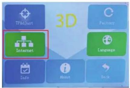
- On the printer, open the menu System. 2. Open the menu Internet.
→ The printer displays its Wi-Fi network name.

-
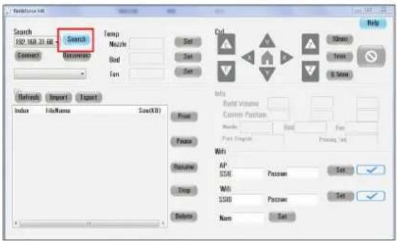
Connect your computer to the printer's Wi-Fi network. 4. Open the Wi-Fi configurator software.
-
Click Search.
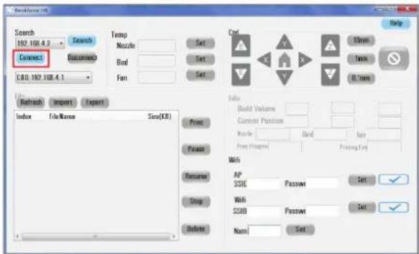

- Click Connect to connect your computer to the printer.
→ The printer will list the les of its internal memory.
13.3 Setting up Wi-Fi indirect mode (computer-to-many printers)
Set up Wi-Fi indirect mode to wirelessly connect your computer to multiple printers.

- Open the Wi-Fi configurator software.
- Enter the SSID and the password of the Wi-Fi network.
- Save the settings with Set.
- Under Wi-Fi, export the Wi-Fi settings to your computer by clicking the symbol √ next to the button Set.
→ A Wi-Fi configuration file is saved to the desktop of your computer.
- Copy the Wi-Fi configuration file to the supplied USB memory stick.

- Connect the USB memory stick to the USB-A port on the printer.
- Open the menu Print.

- Click the network configuration file.
→ the display shows the IP address of the printer to indicate successful connection.

→ if the display shows the IP address "0.0.0.0", then Connect your computer to the Wi-Fi network connection failed. Check if the SSID and the password are correct.
10. (For multiple printers) Load the same network configuration file onto the other printers.

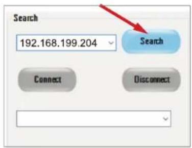
- Click Search.

- Click the down arrow and select your desired printer from the list. You can use the IP address displayed behind each printer name to distinguish the printers in the list.
- Click Connect to connect your computer to the printer.
14 Setting up Cura
14.1 Installing Cura on Windows®
-
Download the Cura installation file from https://ultimaker.com/software/ultimaker-cura.
-
Double-click the downloaded installation file and follow the on-screen installation steps.
14.2 Installing the Windows ^® driver
The printer requires a driver to interface with the Cura software.
Verify driver availability
The required driver may already be installed. Verify driver availability in the device manager to determine if you need to install the driver.
- Open the Device Manager.
- Expand the section Ports (COM & LPT) and check for PL2303[name]. If the driver is not installed, install it.

Installing the driver
- Connect the supplied USB memory stick to your computer.
- Then double-click the file "PL2303_Prolific_GPS_1013_20090319.exe" on this driver.
14.3 Installing Cura on MacOS
- Download the Cura DMG file from https://ultimaker.com/software/ultimaker-cura
- Double-click the downloaded installation file and follow the on-screen installation steps.
14.4 Configuring Cura for the Pro 10+
After installing Cura, follow the steps in the wizard to set up Cura for the Pro 10+.
- Start the Cura software.
- Follow the on-screen steps of the wizard. Under the step Add Printer, select Renkforce > Renkforce Pro 10+. See screenshot.
- Complete the setup by following the remaining steps of the wizard.
→ The Cura software is configured for the Pro 10+.

15 Cleaning
15.1 Cleaning the printer
Important:
- Do not use aggressive cleaning agents, rubbing alcohol or other chemical solutions. They damage the housing and can cause the product to malfunction. - Do not immerse the product in water.
- Disconnect the printer from the power supply.
- Let the printer cool down to room temperature.
- Clean the printer with a dry, fibre-free cloth.
15.2 Cleaning the magnetic mat
Gently scrape off filament residue from the magnetic mat with a blunt knife.
15.3 Cleaning the nozzle
- Let the nozzle cool down to room temperature.
- Carefully wipe the nozzle after each print with a soft cloth.
Removing residual filament
- Heat the extruder for a few minutes, then stop heating.
- Wear heat-resistant gloves.
- Add a few drops of anhydrous alcohol to a soft cloth and remove the residual filament from the nozzle.
15.4 Cleaning the inside of the nozzle
Clean the inside of the nozzle if residue obstructs the filament flow.

CAUTION
Hot nozzle and molten filament
Touching hot nozzle or molten filament can cause burns
● ● Wear heat-resistant gloves before touching
- Wear heat-resistant gloves.
- Heat the extruder.
- Unload the filament. Follow the instructions in [▶ 12.6 Replacing filaments].
- Repeatedly push the small needle into the nozzle to remove residue.
- Load the filament again. Follow the instructions in [▶ 12.6 Replacing filaments].
15.5 Cleaning the extruder


CAUTION
Hot nozzle and molten filament
Touching hot nozzle or molten filament can cause burns
● ● Wear heat-resistant gloves before touching
- Unload the filament. Follow the instructions in [▶ 12.6 Replacing filaments].
- Heat the extruder.
- Wear heat-resistant gloves.
- Insert the ejector rod through the filament inlet into extruder. See Fig. 1.
- Move the ejector rod up and down repeatedly to loosen residue.
→ Residue will fall out.
- Load the filament again. Follow the instructions in [▶ 12.6 Replacing filaments].

natural_image
Close-up of hands assembling a mechanical component with two red-circled detail (no visible text or symbols)Fig. 1
16 Maintenance
16.1 Calibrating the Z-sensor
Calibrate the Z-sensor after replacing the nozzle or the hotend. The calibration of the Z-sensor directly affects the precision of the "Auto-levelling" function.
- Disconnect the power supply.
- Let the nozzle cool down to room temperature.
- Remove the silicon cover of the extruder.
- On the right side of the Z-sensor, loosen the two screws. Check that the Z-sensor can be moved up and down.
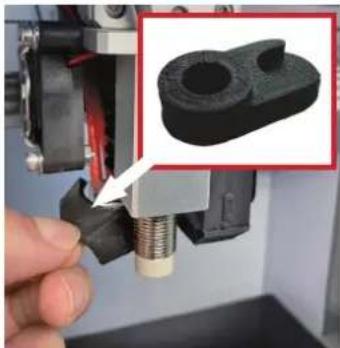
- Place the Z-sensor calibration tool under the Z-sensor and the nozzle. See Fig. 2.
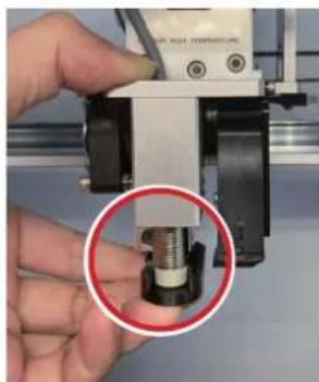
- Move the Z-sensor up or down until the Z-sensor and the nozzle align with the top of the Z-sensor calibration tool. See Fig. 3.
- Tighten the screws on the Z-sensor.
- Calibrate the print bed.
natural_image
Close-up of a hand holding a mechanical component with a magnified inset showing a 3D-printed part (no text or symbols visible)Fig. 2 Fig. 3
natural_image
Close-up of a hand holding a 3D printer with a red circle highlighting a mechanical component (no visible text or symbols)16.2 Replacing the fuse
- Remove the mains cable from the power inlet on the printer.
- Pry open the fuse box. See Fig. 4.
- Remove the blown fuse.
- Insert a new fuse of the same specifications.
- Close the fuse box.
- Connect the mains cable to the power inlet on the printer.

natural_image
Close-up of a black electrical outlet switch with red indicator lights, partially connected by a tool (no visible text or symbols)Fig. 4
17 Storage
- Disconnect the power supply.
- Unload the filament.
- Clean the printer.
- Let the printer cool down to room temperature.
- Store the printer in a dry, dust-free location out of the reach of children.
Note:
PLA filaments will over time absorb moisture and dust when exposed to the open air, which can affect the printing quality. Seal the filament in an air-tight container when not in use.
18 Troubleshooting
| Problem Possible solution | |
| No power supply. Display does not switch on. | Check mains connection. |
| Check fuse. Replace fuse if blown. | |
| Filament snaps. Check that filament | spool turns freely. |
| Check if filament is trapped on the way from spool to extruder. | |
| Too little filament is extruded. Clean | the inside of the nozzle. |
| Clean the extruder. | |
| Nozzle touches print bed. Calibrate | the print bed. |
| Printed object has defects. | Check that set temperature matches temperature requirements of the filament in use. |
| Remove residual filament from nozzle. |
19 Disposal

This symbol must appear on any electrical and electronic equipment placed on the EU market. This symbol indicates that this device should not be disposed of as unsorted municipal waste at the end of its service life.
Owners of WEEE (Waste from Electrical and Electronic Equipment) shall dispose of it separately from unsorted municipal waste. Spent batteries and accumulators, which are not enclosed by the WEEE, as well as lamps that can be removed from the WEEE in a non-destructive manner, must be removed by end users from the WEEE in a non-destructive manner before it is handed over to a collection point.
Distributors of electrical and electronic equipment are legally obliged to provide free take-back of waste. Conrad provides the following return options free of charge (more details on our website):
in our Conrad offices
at the Conrad collection points
at the collection points of public waste management authorities or the collection points set up by manufacturers or distributors within the meaning of the ElektroG
End users are responsible for deleting personal data from the WEEE to be disposed of. It should be noted that different obligations about the return or recycling of WEEE may apply in countries outside of Germany.
20 Declaration of Conformity (DOC)
Conrad Electronic SE, Klaus-Conrad-Straße 1, D-92240 Hirschau hereby declares that this product (Pro 10+) conforms to the following directive(s):
RED directive 2014/53/EU
EN 300 220-1 V3.2.1
EN 300 220-2 V3.2.1
EN 301 489-1 V2.2.3
EN 301 489-3 V2.1.1
EN 62479:2010
EN IEC 62368-1:2020 + A11:2020
MD directive 2006/42/EC
EN 60204-1:2018
EN ISO 12100:2010
RoHS directive 2011/65/EU + 2015/863/EU
Click on the following link to read the full text of the EU declaration of conformity:
www.conrad.com/downloads
Enter the product item number in the search box. You can then download the EU declaration of conformity in the available languages.
21 Technical data
21.1 Power supply
Input voltage....100 - 240 V/AC, 50 - 60 Hz
Power consumption....600 W
Fuse.....F10AL, 250 V
21.2 Printing
Supported file format......AMF / STL / OBJ / gcode
Printing technology....FDM
Build volume 360 x 360 x 400 mm
Supported filament diameter ∅.....1.75 mm
Supported filament type.... PLA, PLA Compound, PETG, ABS, ASA, PC, PP, PA, TPU 95A, TPU 87A, TPE 83A, Carbon fiber, PEEK, PEI
Nozzle diameter....0.4mm
Print layer thickness .... min. 0.05 mm / max. 0.3 mm
Extruder temperature.....max. 260 °C
Print bed temperature.....max. 120 °C
Print speed 20 – 120 mm/s
Building accuracy ....+/-100 μm
21.3 Software
Software compatibility....Windows ^® 7 and higher
Supported slicing software .... Ultimaker Cura, Slic3r
21.4 Wi-Fi module
Wi-Fi frequency range 2412 - 2472 MHz (802.11b/g/n20)
Wi-Fi transmission power 802.11b : 10.91 dBm
802.11g : 11.98 dBm
802.11n-HT20: 13.04 dBm
Transmission distance....50 m
21.5 Environment
Operating conditions.... 0 to +40 °C, 30 - 90% relative humidity (non-condensing)
Storage conditions.... 0 to +40 °C, 30 - 90% relative humidity (non-condensing)
21.6 Others
Dimension without spool....560 x 560 x 760 mm
Weight 57 kg
This is a publication by Conrad Electronic SE, Klaus-Conrad-Str. 1, D-92240 Hirschau (www.conrad.com).
All rights including translation reserved. Reproduction by any method, e.g. photocopy, microfilming, or the capture in electronic data processing systems require the prior written approval by the editor. Reprinting, also in part, is prohibited. This publication represents the technical status at the time of printing.
Copyright 2024 by Conrad Electronic SE.


- Touchscreen-Menüs
- Not-Halt
- Manuelles Nivellieren des Druckbetts
- Wartung
- Aufbewahrung
- Introduction
- Operating Instructions for download
- Intended use
- Delivery content
- Description of symbols
- Operating elements
- Printer
- Print head
- Print bed
- Touch screen menus
- System menu
- Tools menu
- Emergency stop
- Manual interface
- Preheating
- Filament
- Fan control
- Print menu
- Print file selection
- Installation
- Installing the spool holder
- Installing the filament tube
- Power supply
- Connecting to power
- Switching on/off
- Before printing
- Calibrating the print bed
- Automated print bed levelling – “Auto-levelling”
- Z-offset calibration
- Manual print bed levelling
- Using "Auto-levelling" to level the print bed
- Calibrating the Z-offset
- CAUTION
- Hot print bed
- Levelling the print bed manually
- After calibration
- Loading filament
- Printing
- Using Cura
- Printing from USB memory stick
- Printing from computer via USB cable
- Printing from computer via Wi-Fi connection
- Removing printed models
- Replacing filaments
- Setting up Wi-Fi printing
- Direct mode (computer-to-printer)
- Indirect mode (computer-to-many printers)
- Using the Wi-Fi configurator software
- Note:
- Setting up Wi-Fi direct mode (computer-to-printer)
- Setting up Wi-Fi indirect mode (computer-to-many printers)
- Setting up Cura
- Installing Cura on Windows®
- Installing the Windows ® driver
- Verify driver availability
- Installing the driver
- Installing Cura on MacOS
- Configuring Cura for the Pro 10+
- Cleaning
- Cleaning the printer
- Important:
- Cleaning the magnetic mat
- Cleaning the nozzle
- Removing residual filament
- Cleaning the inside of the nozzle
- Hot nozzle and molten filament
- Cleaning the extruder
- Maintenance
- Calibrating the Z-sensor
- Replacing the fuse
- Storage
- Disposal
- Declaration of Conformity (DOC)
- RED directive 2014/53/EU
- MD directive 2006/42/EC
- RoHS directive 2011/65/EU + 2015/863/EU
- Technical data
- Power supply
- Printing
- Software
- Wi-Fi module
- Environment
- Others
Brand : Renkforce
Model : Pro 10+
Category : 3D Printer