Pro Capture AIO 4K Plus - Uncategorized Magewell - Free user manual and instructions
Find the device manual for free Pro Capture AIO 4K Plus Magewell in PDF.


| Product Type | PCIe Video Capture Card |
| Model | Pro Capture AIO 4K Plus |
| Interface | PCI Express (PCIe) 2.0 x4 |
| Input Interfaces | HDMI, DVI, VGA, Component (YPbPr), Composite (CVBS), S-Video, SDI |
| Maximum Input Resolution | 4096 x 2160 (4K) |
| Maximum Output Resolution | 4096 x 2160 (4K) |
| Onboard Memory | 256 MB |
| Supported Operating Systems | Windows 7/8/8.1/10 (x86/x64), Windows Server 2008/2008 R2/2012/2012 R2/2016 |
| Dimensions (approx.) | 80 mm x 120 mm (half-height PCIe card) |
| Weight (approx.) | 100 g |
| Power Consumption | 10 W (estimated from PCIe slot) |
| Board ID Setting | Rotary switch (hexadecimal 0-F) |
| Multi-Card Support | Yes, up to 16 cards with unique IDs |
| Video Capture Software | Compatible with AMCap, OBS, etc. |
| On-Screen Display (OSD) | PNG overlay with alpha channel |
| Low Latency Mode | Yes, for real-time applications |
| Deinterlacing Modes | Weave, Blend, Top/Bottom field only |
| EDID Management | Load, save, reset EDID |
| Video Crossbar | Select input type manually |
| Timing Adjustment | Auto/manual phase, horizontal alignment, custom timings |
| Operating Temperature | 0°C to 40°C (estimated) |
| Safety Certifications | RoHS, CE (estimated) |
Frequently Asked Questions - Pro Capture AIO 4K Plus Magewell
User questions about Pro Capture AIO 4K Plus Magewell
0 question about this device. Answer the ones you know or ask your own.
Ask a new question about this device
Download the instructions for your Uncategorized in PDF format for free! Find your manual Pro Capture AIO 4K Plus - Magewell and take your electronic device back in hand. On this page are published all the documents necessary for the use of your device. Pro Capture AIO 4K Plus by Magewell.
USER MANUAL Pro Capture AIO 4K Plus Magewell
Pro Capture Family Driver User Manual
© 2022, Nanjing Magewell Electronics Co., Ltd. All rights reserved.
TABLE OF CONTENTS
03 Safety Information
04 Hardware Installation
05 Driver Installation
08 Settings
Info 08
Timing 10
OSD 14
HDMI 15
Video 16
Input 19
Output 29
Video Crossbar 29
Safety Information
Electrical Safety
- When devices are installed, make sure that the computer is turned off before the signal cables are connected. If possible, disconnect all power cables from the computer before adding a device.
• Make sure that your power supply is set to the correct voltage for the supply in your area. - If you are not sure about the voltage of the electrical outlet you are using, contact your local power company.
- If the power supply is broken, do not try to fix it by yourself. Contact a qualified service technician or your retailer.
Operation Safety
- Before installing devices on your motherboard, carefully read all the manuals that come with the package.
- Before using the product, make sure all cables are correctly connected and the power cables are not damaged. If you detect any damage, contact your dealer immediately.
• To avoid short circuits, keep paper clips, screws, and staples away from connectors, slots, sockets and circuitry. - Avoid dust, humidity, and extreme temperature. Do not place or use the product in any area where it may be exposed.
- Place the product on a stable surface.
- If you encounter technical problems with the product, contact a qualified service technician or your retailer.
Hardware Installation

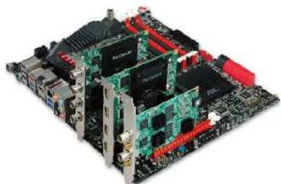
(a) Sample Motherboard inside the chassis
natural_image
R displayed on a computer motherboard with multiple green circuit boards and red connectors (no visible text or labels)(b) Motherboard inside the chassis with capture cards installed
(c) Rotary switch
Procedure
- Turn off the computer power and unplug the power cables.
- Remove the chassis cover and locate the PCI Express slot(s), as shown in figure (a).
- Move the retaining clip to the open position (usually by pushing down on it) on the PCIe slot into which you are going to insert the card.
- Plug the video capture card into the slot and make sure it is firmly seated, as shown in figure (b).
- Screw the card onto the rear panel of the chassis.
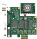
- If multiple cards are to be installed, we suggest that you set card number of each card before installation. There is a rotary switch on each card marked in hexadecimal from 0 to F which enables you to set specific number for each card according to their needs, as shown in figure (c). After the ID numbers are set, users can install the cards according to steps 3-5.
- Restore the chassis cover.
- For DVI cards and others with analogue inputs, use the included breakout cable to connect the video source and the video capture card.
- Reconnect all the power cables.
Driver Installation
System requirement
- Minimum requirements: CPU - Intel Core 2 Duo E7200; RAM - 1GB; integrated graphics card; integrated sound card.
-
Recommended: CPU - Intel Core i7-6800K @ 3.40GHz; RAM - 8GB; Graphics Card - NVIDIA Quadro M4000.
• Supported Operating Systems: -
Windows 7 x64/x86
- Windows 8 x64/x86
- Windows 8.1 x64/x86
- Windows 10 x64/x86
- Windows Server 2008 x64/x86
• Windows Server 2008 R2 x64/x86 - Windows Server 2012 x64/x86
- Windows Server 2012 R2 x64/x86
- Windows Server 2016
Driver Installation and Uninstallation
Driver Installation Procedure
- Double-click MWDriverInstaller_xxx.exe to install the program.
i. If there is an existing driver in the system, the program will compare the version automatically, and you are prompted whether to uninstall the existed one.
ii. If you are going to uninstall the existed one, click Yes, then continue to install the current driver, follow the prompts to complete the installation process.
- To confirm whether the installation is successful.
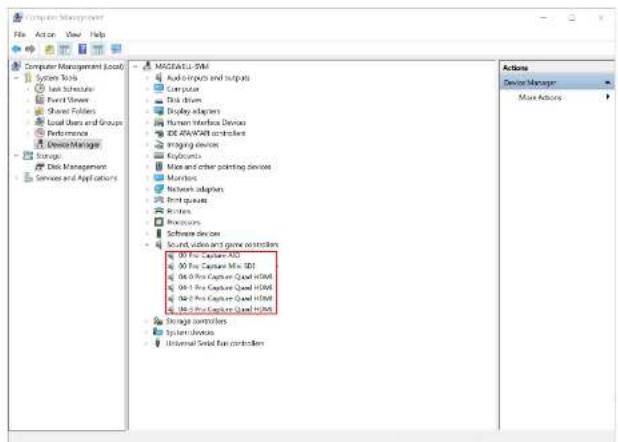
i. Right click This PC and select Manage > Device Manager > Sound, video and game controllers, and then check if your capture card model(s) are shown in the list of installed devices.
In the device list, you can see all the capture cards that are installed in this computer. The number before the Pro Capture card name is the ID (E.g. 00 or 04 in the example), which is set via the rotary switch on the card. For multi-channel cards, the channel number will be added after the ID number. (E.g. 04-0, 04-1, 04-2, 04-3 for a Quad card)
i. Choose a capture device and right click Properties > Driver. Check the version of the current driver. If it is the same as the installed driver version, the installation has been successful.
Driver Uninstallation Procedure
- Select the Start button, then select Settings > Apps.
- Choose the Magewell Pro Capture Driver version program, and then select Uninstall.
- To confirm whether the uninstallation was successful.
i. Right click This PC and select Manage > Device Manager > Sound, video and game controllers.
ii. Check that your capture card model(s) are removed from the list of installed devices.
Settings
The attributes of the Pro Capture Card can be ticked and modified through video capture software, e.g. AMCap or OBS. The parameters are as follows.
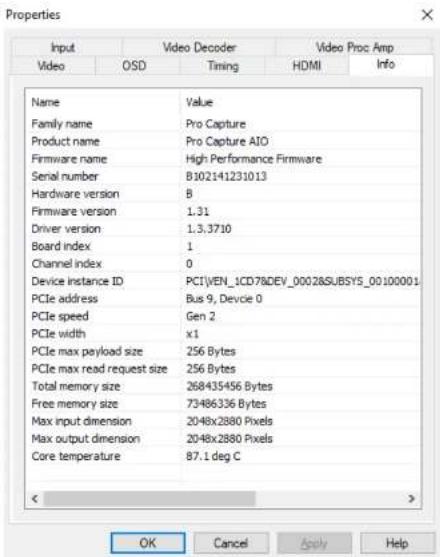
Info
| Item Item Description | |
| Family name | Shows the name of the product family (Pro Capture). |
| Product name Shows the name of this specific product. | |
| Firmware name Shows the name of the firmware. | |
| Serial number Shows the serial number. | |
| Hardware version Shows the hardware version of this product. | |
| Firmware version Shows the firmware version currently installed. | |
| Driver version Shows the driver version currently in use. | |
| Board index | Shows the board ID number, a hexadecimal value from 0 to F. Set via a rotary switch on the card. It will be 0 for a mini card. |
| Channel index | Shows the zero-based channel number. It will be 0 for a single channel card; 0/1 for a dual channel card; 0/1/2/3 for a quad channel card. |
| Device instance ID | The key value can be found in the registry at:Registry\Computer\HKEY_LOCAL_MACHINE\SYSTEM\CurrentControlSet\Services\ProCapture. |
| PCIe address Shows the PCIe bus number and device number. | |
| PCIe speed Shows the PCIe bus speed (e.g. Gen1, Gen 2). | |
| PCIe width | Shows the PCIe bus bandwidth (options are x1, x2, x4, x8, x16). |
| PCIe max payload size | Shows the max length of valid PCIe bus data. |
| PCIe max read request size | Shows the max size of PCIe bus read request. |
| Total memory size | Shows the current onboard memory size (e.g. 256MB). |
| Free memory size Shows the currently unused memory size. | |
| Max input dimension | Shows the max video input resolution. |
| Max output dimension | Shows the max video output resolution. |
| Core temperature Shows the current temperature of FPGA chip core. | |
Timing
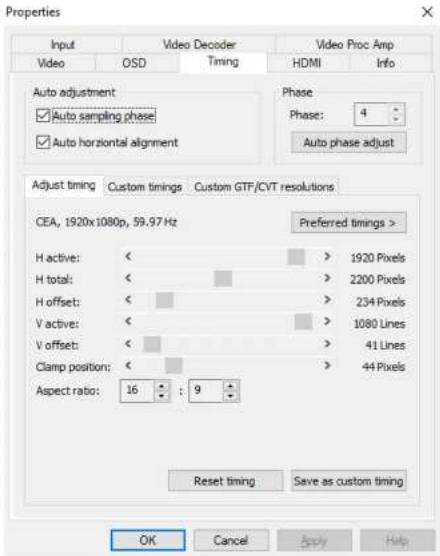
When the capture card in use has a component or VGA capture interface, this Timing tab will be shown. The parameters can only be set when the input signal is either a component video signal or a VGA video signal. It is provided by Pro Capture AIO, Pro Capture DVI, Pro Capture Dual DVI video cards.
| Item Name Item Description | |
| Auto sampling phase | Ticked by default. The capture card will automatically fine-tune the video to achieve optimum clarity. |
| Auto horizontal alignment | Ticked by default. The card automatically makes adjustments to attain the correct horizontal position of the video. |
| Phase | It can be manually or automatically adjusted. The range is 0-63. |
Adjust timing
When the signal is being captured, the device will automatically recommend one or more timings as shown in the Preferred timings list. The first one in the list will be shown above the timing adjustment section by default. If none of the recommended timing matches, you can drag the slider bars below to manually adjust.
| Item Name Item Description | |
| H active Active horizontal picture width. | |
| H total Total horizontal pixels captured. | |
| H offset | Set the value to move the image horizontally.Note: The dimensions have the following relation: H total >= H active + H offset, for example, H active = 1920, H total = 2200, as a result, H offset <= 280. |
| V active Active vertical picture width. | |
| V offset | Set the value to move the image vertically.Note: The dimensions have the following relation: V total >= V active + V offset, for example, V active = 1080, V total = 1125, as a result V offset <= 45. |
| Clamp position | Used to adjust the sampling point of A/D conversion to remove interference, usually do not need to be modified. |
| Aspect ratio Set the aspect ratio of input video. | |
To add a new custom timing:
- Click Save as custom timing to save the correct timing setting in the Custom Timings tab. When the same video signal is connected again, the card will automatically show the video according to the previously saved profile.
To reset timing:
- Click Reset timing to set the custom timing as the current timing. If no custom timing is available, the first one in the recommended list will be set as the current timing.
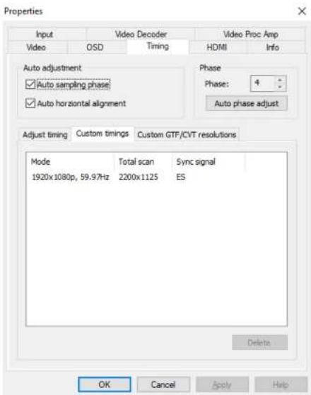
| Item Name Item Description | |
| Custom timings | This shows the saved custom setting in Adjust timing, including resolution, frame rate, pixel sampling, and synchronization method. When the same video signal is connected again, the card will automatically show the video according to the previously saved setting. If the user wants to delete the past setting(s), they can choose the setting in Custom timings and click Delete. |
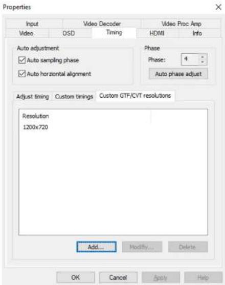
| Item Name Item Description | |
| Custom GTF/CVT resolutions | If adjustments made in the Timing Adjustment tab cannot achieve satisfactory results, users can manually add a resolution that meets GTF or CVT standards. |
To add a new resolution:
- Click Add and input a valid Width and Height
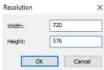
To modify or delete a resolution:
- Click a resolution, then click Modify or Delete to change existing values.
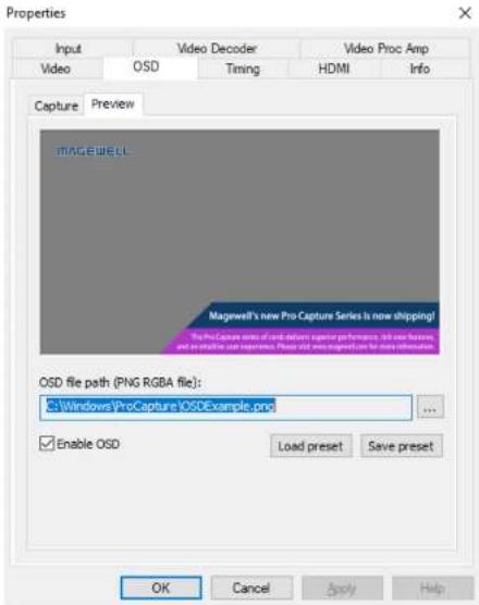
OSD
An image with transparency (i.e. alpha channel) can by overlaid on the incoming video by using the OnScreenDisplay (OSD) function.
- Browse to select a PNG RGBA image from local folder.
- Click Enable OSD to activate the overlay.
- Click Save preset to save the current image/path as a template. Then users can click Load preset to load the image in the previously saved OSD file path.
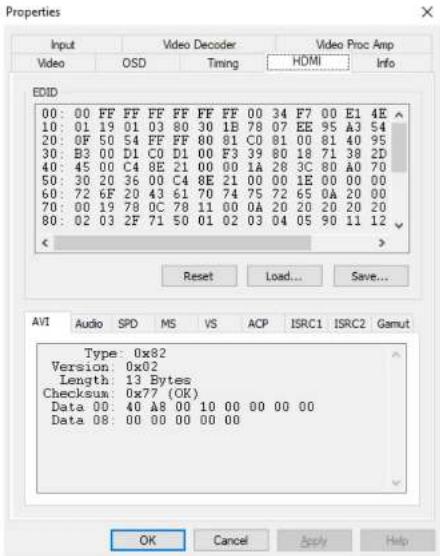
HDMI
When the capture card has one or more HDMI interface(s), the HDMI tab will be available in the control panel.
| Item Name Item Description | |
| EDID | Standard data in VESA format. It shows the supplier's information, max resolution, color settings, manufacturer's preset, frequency range, name of monitor and string of serial number. |
| Reset Resets the current EDID to the default one. | |
| Load Loads a local EDID file. | |
| Save Saves the current EDID. | |
| AVI | Shows type, version and verify bit of the video stream and the verification result. |
| Audio | Shows the type, version and verify bit of the audio stream and the verification result. |
| SPD, MS, VS, ACP, ISRC1, ISRC2, Gamut | Show information of the HDMI InfoFrame. |
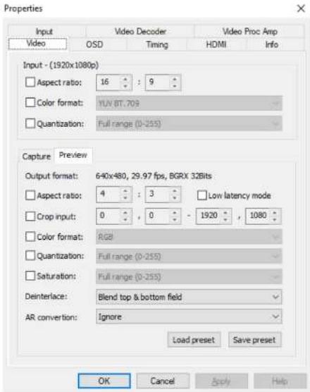
Video
By default, Input shows the input information extracted from the signal. If a non-standard signal is incorrectly recognized by the capture device, users can manually adjust the parameters.
| Item Name Item Description | |
| Aspect ratio | Shows the aspect ratio of the current input. If the box is ticked (The shortcut key is the Space key), users can adjust the aspect ratio by clicking on the arrows (Shortcuts are up and down arrow keys). |
| Color format | Shows the color space of the current input. If the box is ticked, other color spaces can be chosen from the drop-down list (The shortcut key is the Enter key). |
| Quantization | If the box is ticked, the quantization values of Full range and Limited range can be chosen. |
Preview/Capture
| Item Name Item Description | |
| Output format | Shows the current resolution, frame rate and color space of the previewed video. When the settings of this stream are changed, the data here will be changed accordingly. |
| Aspect ratio Shows the aspect ratio of the current output. | |
| Low latency mode | The latency will be reduced when low latency mode is chosen. It can be very useful and the benefit is obvious in video conferencing.Take video capture card with PCIe 2.0 x1 (such as ProCaptureAIO) for example, the comparison of three modes of data transfer, normal mode, low latency mode, low latency mode and partial completion notification mode, is shown as follows.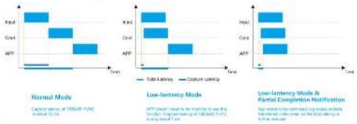 |
| Crop input | Adjusts the captured pixel area from the input video by cropping the edges, using X/Y pixel values for top/left and bottom/right. |
| Color format Shows the color space for capturing. If the box is ticked, other color spaces can be chosen. | |
| Quantization Users can choose Full range or Limited range. | |
| Saturation | Shows the grades of saturation of the input signal. Options are Full range, Limited range and Extended GAMUT range. |
| Deinterlace | The range of values:Weave: Combines the top field and bottom field into a frame without any other process. Usually used to capture the original data.Blend too & bottom field: Merges two fields together and deinterlaces via FPGA to ensure a CPU-free video processing.Top field only: Copy the top field data in vertical direction as a full frame.Bottom field only: Copy the bottom field data in vertical direction as a full frame.Deinterlacing is a process of converting interlaced video into a non-interlaces form, and half size the frames after processing. For example, the input signal is a 60 field/s interlace signal, the device delivers a 30 TPS progressive signal after processing. |
| AR conversion | Aspect Ratio conversion mode options include:Ignore: Ignore the original aspect ratio and stretch to full-screen.Cropping: Expand to full screen and remove parts of the image when necessary to keep the original aspect ratioPadding: Fit to screen and add black borders to keep the original aspect ratio. |
| Load preset Loads the saved presets. | |
| Save preset Saves the current settings as presets. | |
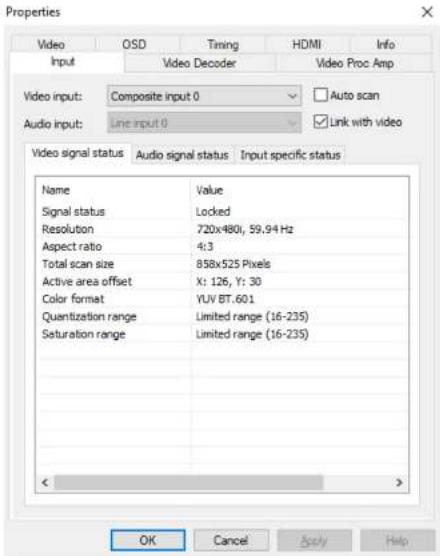
Input
| Item Name Item Description | |
| Auto scan | Automatically scans the input signals by default. If the box is unticked, users can manually select the input signal. |
| Link with video | Automatically scans for an audio signal embedded in the video signal by default. If the video signal is changed, the audio signal will automatically be changed to try to match the video signal. If the box is unticked, users can manually select the audio signal. |
Note: when both of them are unticked, digital video signal, e.g. HDMI, SDI, can link with all kinds of audio, while analog video signal can only link with analog audio.
Video signal status
| Item Name Item Description | |
| Signal status | Shows the video input signal information parsed by the device, shown as Locked, Unsupported, Not Present. |
| Resolution | Shows resolution and frame rate of the input video. If the input signal changes, this display will be changed accordingly. |
| Aspect ratio Shows the aspect ratio of input video source. | |
| Total scan size Shows the total scanned pixel area. | |
| Active area offset Shows the current horizontal and vertical offset of the active signal within the total area scanned. | |
| Color format Shows the chosen color space of the video signal. | |
| Quantization range | Shows the luminance quantization range Options: Full range (e.g. 0-255) or Limited range (e.g. 16-235 - for 8-bit inputs). |
| Saturation range | Shows the saturation of the input signal. Options are Full range, Limited range or Extended GAMUT range. |
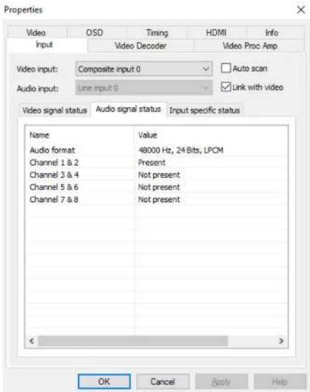
Audio signal status
| Item Name Item Description | |
| Audio format | Shows the sampling frequency, bit depth and format of the current audio. |
| Channels 1&2Channels 3&4Channels 5&6Channels 7&8 | Shows the current audio stream status for each channel pair. Options arePresentor Not present.NOTE: These values only indicate the presence of audio signal channels, and are in no way indicative of audio signal levels. An audio channel can be shown asPresenteven if no actual audio data is being received. The analogue line input will always be shown asPresenteven when no audio cable is connected. |
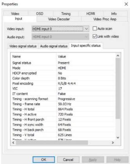
- When HDMI signal is connected, the Input specific status tab is as follows:
| Item Name Item Description | |
| Signal status Options are Present or Not present. | |
| Mode Shows input signal mode. | |
| HDCP encrypted | Shows whether the signal is HDCP encrypted. Options are Yes or No. |
| Color depth | Shows the color depth of the current video. Common values are 8 bit, 10 bit and 12 bit. |
| Pixel encoding Shows pixel encoding, e.g. R/G/B, Y/U/V, Y/Cb/Cr. | |
| VIC Standard video identification code. | |
| IT content | If True, pictures are compressed according to common IT practice, or particular requirements derived from IT practice. |
| Timing-scanning format | Shows the scan format, e.g. Progressive, Interlaced. |
| Timing frame rate Shows the current frame rate. | |
| Timing-H total Shows total horizontal pixels captured. | |
| Timing-H active Shows active horizontal picture width. | |
| Timing-H front porch | Shows pixel width between the end of the active horizontal picture and the start of the horizontal sync pulse. |
| Timing-H sync width | Shows width of the horizontal sync pulse. |
| Timing-H back porch | Shows pixel width between the end of the horizontal sync pulse and the start of the next active horizontal picture line. |
| Timing-V total | Shows total vertical pixels (i.e. Picture lines) captured. |
| Timing-V active Shows | active vertical picture height. |
| Timing-V front porch | Shows number of lines between the last line of the active vertical picture area and the start of the vertical sync pulse. |
| Timing-V sync width | Shows width of the vertical sync pulse, in lines. |
| Timing-V back porch | Shows number of lines between the end of the vertical sync pulse and the start of the next active horizontal picture line. |
NOTE:
- When the input video signal is in interlaced format, the table will include information for each field separately (Field-0 and Field-1) in the vertical direction.
- When DVI signal is connected, the parameters in the Input specific status tab is the same as those of HDMI.
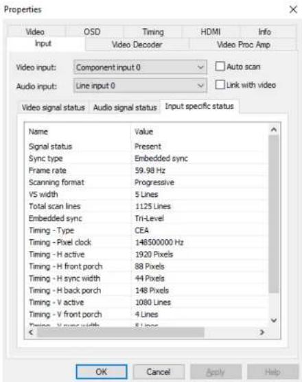
- When component signal is connected, the Input specific status tab is as follows:
| Item Name Item Description | |
| Signal status Options are Present or Not present. | |
| Sync type Shows the type of synchronization, e.g. Embedded. | |
| Frame rate Shows the frame rate of the input video. | |
| Scanning format Options are Progressive or Interlaced. | |
| VS width Shows the width of the vertical sync pulse, in lines. | |
| Total scan lines Shows total number of scanned lines. | |
| Embedded sync | Shows the embedded synchronization method,Options are Bi-Level or Tri-Level. |
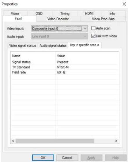
- When CVBS signal is connected, the Input specific status tab is as follows:
| Item Name Item Description |
| Signal status Options are Present or Not present |
| TV Standard Options are PAL, NTSC, SECAM. |
| Field rate The current field frequency of the video signal. |
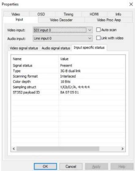
- When SDI signal is connected, the Input specific status tab is as follows:
| Item Name Item Description | |
| Signal status Options are Present or Not present. | |
| Type Shows the current video signal type. | |
| Scanning format | Options are Progressive, Interlaced, Segmented Frame. |
| Color depth | Shows the color depth of the current video, e.g. 8/10/12 bit. |
| Sampling structure Shows signal type and sampling ratios. | |
| ST352 payload ID | Shows the current video format of SDI, e.g. color format, aspect ratio. |
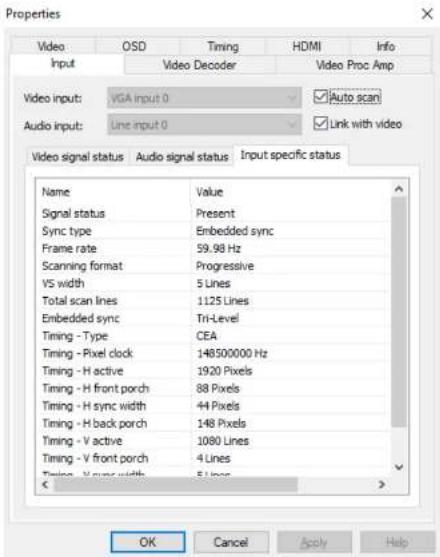
- When VGA signal is connected, the Input specific status tab is as follows:
| Item Name Item Description | |
| Signal status Options are Present or Not present. | |
| Sync Type Shows the type of synchronization. | |
| Frame rate The frame rate of the video source. | |
| Scanning format Options are Progressive or Interlaced. | |
| VS width Shows width of the vertical sync pulse, in lines. | |
| Total scan lines Shows total number of scanned lines. | |
| Timing-Type Shows type of timing standard used. | |
| Timing-Pixel clock Shows the pixel-scanning frequency. | |
| Timing-H active Shows active horizontal picture width, in pixels. | |
| Timing-H front porch | Shows pixel width between the end of the active horizontal picture and the start of the horizontal sync pulse. |
| Timing-H sync width | Shows width of the horizontal sync pulse, in pixels. |
| Timing-H back porch | Shows pixel width between the end of the horizontal sync pulse and the start of the next active horizontal picture line. |
| Timing-V active Shows active vertical picture height, in lines. | |
| Timing-V front porch | Shows number of lines between the last line of the active vertical picture area and the start of the vertical sync pulse. |
| Timing-V sync width | Shows width of the vertical sync pulse, in lines. |
| Timing-V back porch | Shows number of lines between the end of the vertical sync pulse and the start of the next active horizontal picture line. |
Output
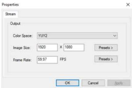
| Item Name Item Description | |
| Color Space | Select from drop-down list manually to modify color space. |
| Image Size | Enter manually or click Presets > and select from those listed. The value shown in bold is the system-preferred value. |
| Frame Rate | Enter manually or click Presets > to select from those listed. The value shown in bold is the system-preferred value. |
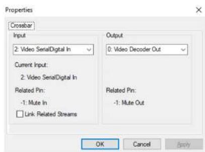
Video Crossbar
Select an Input signal type from the drop-down list, Current Input is auto-detected by the system. The selected signal should be the same as the actual one, otherwise, video will not be displayed correctly. You can set the Video
Crossbar after setting the value of EnableXBar as 1 in the registry at: \Computer\HKEY_LOCAL_MACHINE\SYSTEM\CurrentControlSet\Services\ProCapture and restarting the computer.
The range of Input values:
- Video Parallel Digital In - SDI signal
- Video Serial Digital In = HDMI signal
- Video RGB In = VGA signal
- Video YRYBY In - YPbPr signal
- Video S-Video In = S-Video signal
- Video Composite In = CVBS signal


- Pro Capture Family Driver User Manual
- TABLE OF CONTENTS
- Safety Information
- Electrical Safety
- Operation Safety
- Hardware Installation
- Procedure
- Driver Installation
- System requirement
- Driver Installation and Uninstallation
- Driver Installation Procedure
- Driver Uninstallation Procedure
- Settings
- Timing
- Adjust timing
- OSD
- HDMI
- Video
- Video Crossbar
Brand : Magewell
Model : Pro Capture AIO 4K Plus
Category : Uncategorized