
HAL:400 - Measurement Seaward - Free user manual and instructions
Find the device manual for free HAL:400 Seaward in PDF.


| Product Type | Portable Appliance Tester (PAT) |
| Brand | Seaward |
| Model | HAL:400 |
| Dimensions | 320 x 260 x 170 mm |
| Weight | 1.2 kg |
| Power Supply | Rechargeable Li-ion battery, 7.4 V, 4400 mAh |
| Display | Backlit LCD, 4.3 inches |
| Test Functions | Insulation resistance, earth continuity, earth bond, leakage current, polarity check |
| Insulation Test Voltage | 250 V, 500 V, 1000 V DC |
| Continuity Test Range | 0.01 Ω – 1000 Ω |
| Safety Category | CAT III 300 V |
| Standards Compliance | IEC 61557, IEC 61010, IEC 61326 |
| Operating Temperature | 0°C to 40°C (32°F to 104°F) |
| Storage Temperature | -20°C to 60°C (-4°F to 140°F) |
| Humidity | 10% to 90% non-condensing |
| Memory Storage | Up to 1000 test results |
| Connectivity | USB (data transfer), Bluetooth (optional) |
| Included Accessories | Test leads, alligator clips, mains power cord, carrying case, user manual |
| Warranty | 2 years (parts and labor) |
| Repair and Spare Parts | Available via Seaward authorized service centers; spare parts include test leads, battery, display unit |
| Cleaning | Wipe with a soft, dry cloth; do not use solvents or abrasive cleaners |
Frequently Asked Questions - HAL:400 Seaward
User questions about HAL:400 Seaward
0 question about this device. Answer the ones you know or ask your own.
Ask a new question about this device
Download the instructions for your Measurement in PDF format for free! Find your manual HAL:400 - Seaward and take your electronic device back in hand. On this page are published all the documents necessary for the use of your device. HAL:400 by Seaward.
USER MANUAL HAL:400 Seaward
natural_image
Red geometric cube logo with interlocking lines (no text or symbols)SEAWARD
GMC-INSTRUMENTS GROUP
HAL:400
QUICK START GUIDE

seaward.com
TESTED, TRUSTED... WORLDWIDE.
LIMITED WARRANTY & LIMITATION OF LIABILITY
SEAWARD Electronic Limited guarantees this product to be free from defects in material and workmanship under normal use and service for a period of 2 years, provided the instrument is serviced and calibrated by an authorised agent in accordance with the manufacturer's instructions. The period of warranty will be effective at the day of delivery.
Manufacturer does not provide any warranty for the following:
• Any normal wear and tear
- Errors or damage caused by: (i) misuse or not using your product in accordance with the user guide, such as if the product has been exposed to moisture, to dampness or to extreme thermal or environmental conditions or to rapid changes in such conditions, to corrosion, to oxidation, to spillage of food or liquid or to influence from chemical products, (ii) using your product with, or connecting it to, any product, accessory, software, or service not manufactured or supplied by the manufacturer, (iii) any products combined with your product by a third party, (iv) damage or errors caused by hacking, cracking, viruses, or other malware, or by unauthorised access to services, accounts, computer systems or networks; or (v) other acts beyond the manufacturer's reasonable control.
This Warranty is not valid:
- If your product, or the software it runs on, has been (i) opened, modified, or repaired without the manufacturer's authorisation, or (ii) repaired with unauthorised spare parts;
- If you have not installed the latest software updates that are publicly available for your product within a reasonable time of their release; or
- If you refuse to give possession of the product to the manufacturer for repair and investigation.
(c) Copyright 2024
All rights reserved. Nothing from this edition may be multiplied, or made public in any form or manner, either electronically, mechanically, by photocopying, recording, or in any manner, without prior written consent from SEAWARD Electronic Limited. This also applies to accompanying drawings and diagrams.
Due to a policy of continuous development SEAWARD Electronic Limited reserves the right to alter the equipment specification and description outlined in this publication without prior notice and no part of this publication shall be deemed to be part of any contract for the equipment unless specifically referred to as an inclusion within such contract.
ENVIRONMENTAL CONDITIONS
The HAL:400 has been designed to perform tests and measurements in a dry environment.
Overvoltage category II 300V.
Pollution degree 2 according to IEC 61010-1.
Protective system IP40 according to IEC 60529.
Electromagnetic compatibility (EMC). Interference immunity and emitted interference conforming to IEC 61326-1, Class B.
USER NOTES
This instrument and its operating instructions are intended for use by adequately trained personnel. Protective measures should be always considered when using any HAL:400 unit. This quick start guide is not intended to be a substitute for the operating manual, which should be read fully.
The following symbols are used in these operating instructions.

Warning of electrical danger!
Indicates instructions must be followed to avoid danger to persons.

Important, follow the documentation!
This symbol indicates that the operating instructions must be adhered to in order to avoid danger.
HAL:400 QUICK START GUIDE
SAFETY NOTES

In order to ensure safe operation of the HAL:400, all notes and warnings in these instructions must be observed at all times.

Do not attempt to turn off the HAL400 while tests are active.

The HAL-400 is intended for use in an indoor dry environment only.

Check the HAL:400 and all associated cables and leads before operating the equipment. Do not use if there are signs of damage. Only use the test leads supplied with the HAL:400.

Prior to testing ensure that all of the test connections on the HAL:400 are fully mated into their intended terminals and that there is no risk of these connection being disconnected. Disconnected or partially mated test connections can lead arcing and/or over heating which may damage the HAL:400, accessories and the piece of the equipment under test. Touching disconnected test connection may lead to an electric shock.

Do not touch any exposed metal parts of the device under test during testing.

Always ensure that the circuit under test is electrically isolated from all other external influences.

Where safe operation of the HAL:400 is no longer possible it should be immediately shut down and secured to prevent accidental operation. It must be assumed that safe operation is no longer possible:
• If the instrument or leads show visible signs of damage or
• The instrument does not function or
• On-screen messages warn against further use or
• After long periods of storage under adverse environmental conditions.

If the HAL:400 is used in a manner not specified by this document then the protection provided by the equipment may be impaired.
PG4 PG5

Do not open the HAL:400, no user serviceable parts.

It is advised to regularly verify the correct operation of the instrument and any associated test accessories.

Prolonged test times using high current may result in the test tips or jaws becoming hot. Care should be taken to avoid contact after long periods of testing.

The HAL:400 can produce voltages of up to 5kVrms and 6kVdc. Ensure that suitable safety precautions have been put in place prior to testing.

The power button on the front of the HAL:400 does not remove power from the HAL:400. Do not position the HAL:400 so that it is difficult to switch the power button on the back of the HAL:400 or remove the mains plug from the HAL:400 or mains supply.

The HAL:400 weighs 18kg. Ensure that when moving and lifting that best practices for manual handling are followed.

Only make a connection to the Remote Earth probe terminal OR the V+ and I+ terminals. If these are connected then this may lead to measurement inaccuracies during the Ground Bond and Continuity tests.

Do not use probes without measurement category on mains circuit.

Do not connect probes to external voltage sources.
HAL:400 QUICK START GUIDE
WHAT'S IN THE BOX?
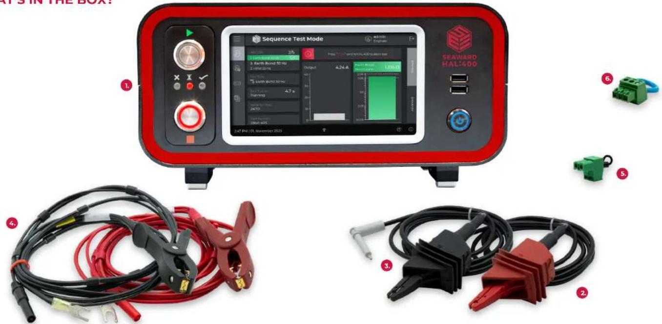
The following items are supplied as part of your new HAL:400 instrument:
| Product Name | Part Number |
| 1. HAL400 Instrument 490A910 | (without Ground Bond)490A913 (with Ground Bond) |
| 2. Hipot Test Lead Red 490A1050 | |
| 3. Hipot Test Lead Black 490A1049 | |
| 4. Earth Bond / Continuity Kelvin Test Lead Sct | 490A1008 |
| 5. Guard Plug 490A1012 | |
| 6. Start / Stop Plug | 490A1048 |
PG6 PG7
Also supplied as standard:
| Product Name | Part Number |
| Power Lead UK | 39044 |
| Power Lead EU | 44B053 |
| Power Lead US | 44B118 |
| Quick Start Guide | 490A590 |
| Calibration Certificate | N/A |
HAL:400 QUICK START GUIDE
HAL:400 TOUR
Front Panel

Feature
- Touch Screen
- Soft Power Button Turn on/off
- Start Button
- Stop Button Aborts test
Function
Main user interface
Initiates test
Feature
- Test Indicators
- USB Slots
Function
Indicates test status:
- Fail
- Test in Progress
For use with peripherals and data transfer
PGB PG9
HAL:400 QUICK START GUIDE
Rear Panel

Feature:
| 1. Beacon Output | Switch from green to red while HAL:400 is active (Optional Accessory) |
| 2. Speaker Output(3.5mm Jack) | Reserved for future use |
| 3. Display Output Output the main display to a large screen | |
| 4. Remote Start / Stop | Allows a remote start/stop button to be used(For integration) |
| 5. Pass / Fail Outputs a pass/fail signal | (For integration) |
| 6. Aux Beacon | Outputs an idle or warning signal (For integration) |
| 7. Guard Switch | Safety cut out switch (Supplied plug must be used in normal use) |
| 8. USB Slots x4 | For connection to peripherals / accessories and for remote PC control |
| 9. Network Cable | Physical internet connection for firmware updates/ cloud connectivity. |
Function:
Feature:
| 10. USB-B Port | Reserved for future use. |
| 11. IO Expander Port | Used with IO Modules (For integration) |
| 12. HAL:PL1 Port | For connection to optional load and leakage module (HAL:PL1) |
| 13. Mains Switch | Incoming supply for the instrument and power switch |
| 14. No Burn Probe Port | No burn earth bond probe port (Optional Accessory) |
| 15. Ground Bond Current + | Output connection for earth bond current |
| 16. Ground Bond Sense + | Output connection for earth bond sense |
| 17. Ground Bond Current - | Return connection for earth bond current |
| 18. Ground Bond Sense - | Return connection for earth bond sense |
| 19. High voltage + | High voltage output (Hipot and insulation resistance) |
| 20. High Voltage Return - | High voltage return (Hipot and insulation resistance) |
PG10 PG11
HAL:400 QUICK START GUIDE
BEFORE FIRST USE
Before using your HAL:400 for the first time, please ensure that you fully inspect the instrument and associated leads for signs of defects.
POWERING ON/OFF
Ensure the Mains switch is set to the ON position at the rear of the HAL400.
To put the HAL:400 to sleep press the Soft Power button for 2 seconds.
GETTING TO KNOW THE HOME SCREEN

Feature: Function:
- Upper Information Bar
- Main area
- Lower Information Bar
- Quick Menu
This area provides access to the Home icon (Seaward logo) and the Log Out functionality. It also provides information relating to the current screen, and the user who is logged into the HAL:400.
This area is used to display menu items, text fields or test information.
This area of the screen shows the Date, Time, Connection Status and provides access to help and about screens (where relevant).
This side menu offers short cuts to the main options screen. This provides fast access to selecting test modes, configuring tests and the device and data menus.
TEST CONNECTIONS
This section describes the test connections for the HAL:400 and how they are designed to be connected to the accessories. All test connections for the HAL:400 are positioned at the rear of the device.
Hipot and Insulation Resistance Test Connections
This section shows the correct method for connection of the HAL400 test instrument for both Hipot and Insulation Resistance Testing.
For Dielectric Withstand and Insulation Resistance testing the test clips or probes are connected as shown across the device to be tested.

Connect the (Red) High Voltage test lead to the High Voltage Terminal (19) and ensure the plug is firmly connected into the socket.
Connect the (Black) Return Test Lead into the Return Terminal (20).
Ensure both clips are connected across the item under test.
Earth Bond and Continuity Test Connections

Only make a connection to the Remote Earth probe terminal OR the V+ and I+ terminals. If these are connected then this may lead to measurement inaccuracies during the Ground Bond and Continuity tests
For Earth Bond and Continuity measurements the Kelvin test lead set is connected as described above for the Continuity measurement.
HAL:400 QUICK START GUIDE


Earth Bond and Continuity Test Connections using No-burn Probe
Additionally the No-Burn probe (optional) accessory can also be used as part of the measuring circuit. This is designed to be used as an alternative to the (Output / Return) connection and replaces the (Red / Black) Kelvin lead.
The No-Burn probe is connected as shown
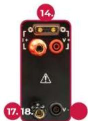

The No-Burn probe maintains the four wire measurement principle. It has a unique press and hold facility to ensure no marking on the product surface due to poor contact resulting in sparking. The probe also serves to provide the operator information via the inbuilt LED during the Earth Bond Test, with the following conditions:
Rapid Flash Slow Flash Solid Light
Probe ready to rest Test in progress Test pass
PG14 PG15
CHECKING AND UPDATING FIRMWARE
It is recommended that on first use of the instrument that a check is performed to ensure the latest firmware is applied. Firmware updates are provided over the air (OTA) by internet connection. Ensure the HAL:400 is connected to an active internet connection via the Ethernet cable (or Wifi Dongle) to proceed.
Checking the Firmware
From the home screen of the HAL:400, press the information icon to the lower right corner of the screen.

The resulting screen, above displays useful information about your HAL:400 including the hardware version, firmware versions. In addition a reminder function for the calibration due date will also be displayed.
HAL:400 QUICK START GUIDE
Updating the Firmware
After confirming the version numbers the next step is to initiate the update by selecting the Firmware update button.
You will then be prompted to select a source for the update, it is recommend that this is performed using the Over The Air function with a HAL:400 connected to the internet.
Once selected a new pop up message appears informing that the unit is checking available firmware.

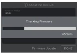
If a new update is available the HAL:400 will display this version, select the new version and press the update button to begin.
Note: If there is no update available, the available update screen will be blank indicating the HAL:400 is on the latest version.

After selecting update the HAL:400 will display a message advising the user that the unit is downloading the firmware and not to power off.
PG 16 PG 17


After completing the download, the HAL:400 will load the new firmware automatically. Upon completion the HAL:400 will require a restart in order to apply the updates.
USER LEVELS
The HAL:400 has three levels of user within the user interface, each with various permissions based on the activities performed with the HAL:400. Each user level can have multiple assigned users.
User Level Permissions
Engineer Has full administrative rights to the HAL:400.
Supervisor Has some administrative rights to the HAL:400, can Add / Edit user lists and accessory behaviour and copy data from the HAL:400. A supervisor level user cannot edit / create test sequences, change HAL:400 behaviour, and cannot add engineer level users to the HAL:400.
Operator Has no administrative rights, can only use the HAL:400 to perform testing as defined by their user options.
Adding a New User
To add a new user, simply tap the Add Icon and define the level of user to be added.
Once selected the Create New User screen will be displayed, with two tabs (General and Settings).
HAL:400 QUICK START GUIDE
General Tab

Allows the user level to be modified if needed and the username to be set. A password is required for both Supervisor and Engineer level users, but can be left blank for operators if a password is not desired.
The beeper settings define when the HAL:400 will produce audible feedback to the operator:
Beeper Setting Provides audible feedback when...
Warning Warning is displayed and requires attention
Barcode Scan User correctly scans a Barcode
Test Condition Test condition signifies a failed test
Settings Tab
For each new user added the available test modes they can access can be chosen by simple check boxes. If a user is not given access to a test mode, then they will not see this mode from their home screen.
The Test Mode screen is the default home screen for an operator level user, if only one option is selected, the HAL:400 will load automatically into this mode.
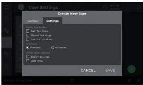
The Test View option defines the default test screen as either the Standard or Advanced View. By default all users created will be set to Standard View.
Visible Other Options will only be present when adding either a new Supervisor or Engineer level user. This will determine whether that user can enter the corresponding menus and edit settings relevant to their login.
So for example if a Supervisor is only required to take data from the unit, but is not to be permitted to add new users, then they should only have the Data Menu option checked.
HAL:400 QUICK START GUIDE
CREATING YOUR FIRST TEST SEQUENCE
The HAL:400 allows you to create test sequences and templates. There are subtle differences between the two, but both are designed to simplify and standardise the testing operation for the user.
Test Sequence Test Template:
List of individual tests that the HAL:400 will run through in the order you create.
Tests or sequences of tests that can be placed within another sequence.
If these templates are altered, then each sequence containing the template is also updated. This is very useful if there is a change to a standard or the procedure you choose to use for your testing. The process for creating either a sequence or a template is identical other than name.
Creating a New Test Sequence
-
Press the 'Configure Sequences and Templates' button from the Home screen.
-
Press the + icon to open the creation menu.
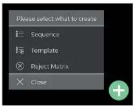
- Select 'Sequence' to begin creation of a new test sequence.
- Press the + icon again to add a step to the sequence you just created.
- Select the item to insert, in this case we will add a new 'Test'.
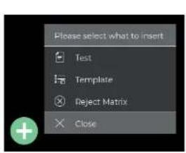

- Select the test type required.

-
Modify the test settings on the right of the screen to match your requirements.
-
Press the 'Save' button SAVE to store the sequence, if this is the first time you have attempted a save, the HAL:400 will prompt you to give the sequence a name.
For full information on creating custom tests please refer to the HAL:400 user manual.
HAL:400 QUICK START GUIDE
UNDERSTANDING A TEST SCREEN
During a Test Sequence or Manual Test, the test screen displays various pieces of useful information:

Feature: Function:
| 1. Test Sequence | This section shows the tests in the sequence, at any one time three tests will be shown on screen. In this example we can see the previous, current and next tests on screen. The item with the green band, shows the previous test, and the colour indicates the status of that test. The current test is shown in Bold, and is always central, the lower test is the next test in the sequence. |
| 2. Test Type | This section shows the type of test currently being performed, in this example the HAL:400 is performing a 50Hz Earth Bond Test. |
| 3. Test Status | This shows the current status of the test, for example Running when the test is under way and has reached its max voltage. |
Feature: Function:
| 4. Serial Number | An optional field displaying the user assigned Serial number, this will be included in the test record. |
| 5. Part Number | An optional field displaying the user assigned part number, this will be included in the test record. |
| 6. Output Display | This column shows the output of the test where this is configurable in settings, for example Current on the Earth Bond Test and Voltage on the Hipot. |
| 7. Leakage Display | This column represents the current state of the test. Included within the graphical display is the measured value along with any target lines for Pass / Fail decision. If the reading is outside of the test parameters, the entire section will turn red to highlight a fail measurement. |
PG 22 PG 23
HAL:400 QUICK START GUIDE
CALIBRATION
To maintain the specified accuracy of the measurement results, the instrument must be recalibrated at regular intervals by Calibrationhouse (Seaward's sister brand) or an authorised Seaward Service Agent. We recommend a recalibration period of one year.
CALIBRATIONHOUSE (UK HEAD OFFICE)

service@calibrationhouse.com

+44 (0) 191 587 8739
calibrationhouse.com
CALIBRATIONHOUSE (USA)

usaservice@calibrationhouse.com
calibrationhouse.com
ONLINE RESOURCES
INFORMATION & MANUAL DOWNLOAD
For more information about your HAL:400, and to access a downloadable version of the operation manual, please visit seaward.com/HAL400
REGISTER YOUR HAL:400 NOW
To activate your 2 year warranty please register your product at seaward.com/register
Notes
HAL:400 QUICK START GUIDE
Notes Notes

natural_image
Abstract geometric logo with red and white interlocking 3D blocks (no text or symbols)SEAWARD
GMC-INSTRUMENTS GROUP
Head Office
+44 (0) 191 586 3511
sales@seaward.com
Seaward, 15-18 Bracken Hill, South West Industrial Estate, Peterlee, County Durham, SR8 2SW, United Kingdom
USA Office
+1 813 886 2775
usasales@seaward.com
Seaward Group USA, 6304 Benjamin Road, Suite 506, Tampa, FL 33634, United States
seaward.com





- SEAWARD
- GMC-INSTRUMENTS GROUP
- HAL:400
- QUICK START GUIDE
- LIMITED WARRANTY & LIMITATION OF LIABILITY
- Manufacturer does not provide any warranty for the following:
- This Warranty is not valid:
- Copyright 2024
- ENVIRONMENTAL CONDITIONS
- USER NOTES
- SAFETY NOTES
- HAL:400 TOUR
- Feature
- Function
- BEFORE FIRST USE
- POWERING ON/OFF
- Feature: Function:
- TEST CONNECTIONS
- Hipot and Insulation Resistance Test Connections
- Earth Bond and Continuity Test Connections
- Earth Bond and Continuity Test Connections using No-burn Probe
- CHECKING AND UPDATING FIRMWARE
- Checking the Firmware
- Updating the Firmware
- USER LEVELS
- User Level Permissions
- Adding a New User
- General Tab
- Settings Tab
- CREATING YOUR FIRST TEST SEQUENCE
- Test Sequence Test Template:
- Creating a New Test Sequence
- UNDERSTANDING A TEST SCREEN
- CALIBRATION
- CALIBRATIONHOUSE (UK HEAD OFFICE)
- CALIBRATIONHOUSE (USA)
- ONLINE RESOURCES
- INFORMATION & MANUAL DOWNLOAD
- REGISTER YOUR HAL:400 NOW
- Notes
- Notes Notes
- Head Office
- USA Office
Brand : Seaward
Model : HAL:400
Category : Measurement