
Z890 VALKYRIE - Motherboard BIOSTAR - Free user manual and instructions
Find the device manual for free Z890 VALKYRIE BIOSTAR in PDF.


| Product Type | Motherboard |
| Model | Z890 VALKYRIE |
| Brand | BIOSTAR |
| Form Factor | ATX, 244 mm x 305 mm |
| CPU Support | Intel® Core™ Ultra 9/7/5 (LGA1851) |
| Chipset | Intel® Z890 |
| Memory | 4 x DDR5 DIMM, up to 192 GB, supports DDR5-9066+(OC) |
| Storage | 6 x M.2 (1x PCIe 5.0 x4, 5x PCIe 4.0 x4) + 4 x SATA III 6Gb/s |
| RAID | RAID 0, 1, 5, 10 for SATA and M.2 NVMe |
| LAN | 1x Realtek RTL8126 5GbE, 1x Realtek RTL8125D 2.5GbE |
| Audio | Realtek ALC1220, 7.1-channel HD Audio, Hi-Fi |
| USB | 1x USB4 Type-C (DP1.4), 1x USB 3.2 Gen2x2 Type-C, 11x USB 3.2 Gen2, 4x USB 2.0 |
| Expansion Slots | 3x PCIe 5.0 x16 (x16, x8, x4 modes) |
| Rear I/O | 2x HDMI 2.1, 1x DP 2.1, 1x USB4 Type-C, 9x USB 3.2 Gen2, 5GbE, 2.5GbE, audio jacks, S/PDIF, SMART BIOS button |
| Internal I/O | 4x SATA III, 1x M.2 E-key (Wi-Fi/BT), USB headers, fan headers, RGB headers, TPM, Thunderbolt |
| Power Connectors | 24-pin ATX, 2x 8-pin CPU power |
| OS Support | Windows 10 (64-bit), Windows 11 (64-bit) |
| Software | UEFI BIOS, BIO-Flasher, Vivid LED DJ, VALKYRIE AURORA utility, SmartEAR, GT Touch, AI Fan |
Frequently Asked Questions - Z890 VALKYRIE BIOSTAR
User questions about Z890 VALKYRIE BIOSTAR
0 question about this device. Answer the ones you know or ask your own.
Ask a new question about this device
Download the instructions for your Motherboard in PDF format for free! Find your manual Z890 VALKYRIE - BIOSTAR and take your electronic device back in hand. On this page are published all the documents necessary for the use of your device. Z890 VALKYRIE by BIOSTAR.
USER MANUAL Z890 VALKYRIE BIOSTAR
FCC Information and Copyright
This equipment has been tested and found to comply with the limits of a Class B digital device, pursuant to Part 15 of the FCC Rules. These limits are designed to provide reasonable protection against harmful interference in a residential installation. This equipment generates, uses, and can radiate radio frequency energy and, if not installed and used in accordance with the instructions, may cause harmful interference to radio communications. There is no guarantee that interference will not occur in a particular installation.
The vendor makes no representations or warranties with respect to the contents here and specially disclaims any implied warranties of merchantability or fitness for any purpose. Further the vendor reserves the right to revise this publication and to make changes to the contents here without obligation to notify any party beforehand.
Duplication of this publication, in part or in whole, is not allowed without first obtaining the vendor's approval in writing.
The content of this user's manual is subject to be changed without notice and we will not be responsible for any mistakes found in this user's manual. All the brand and product names are trademarks of their respective companies.
The terms HDMI and HDMI High-Definition Multimedia Interface, and the HDMI Logo are trademarks or registered trademarks of HDMI Licensing Administrator, Inc. in the United States and other countries.

Avoidance of electrostatic operation rules
Electrostatic discharge can seriously damage your device, Take special care when handling motherboards and other system devices, Avoid unnecessary contact with system parts on the motherboard, Keep working in an antistatic environment, Avoid electrostatic discharge that may damage the motherboard, When inserting or removing devices in your chassis. Make sure the power is off. The manufacturer is not responsible for any damage to the motherboard caused by failure to comply with this operating rule or failure to comply with safety regulations.

Warning
Motherboards are easily damaged by electrostatic discharge. Please follow the operating rules.

Table Of Contents
Chapter 1: Introduction......4
1.1 Before You Start 4
1.2 Specifications....5
1.3 Rear Panel Connectors....7
1.4 Motherboard Layout 8
Chapter 2: Hardware installation....9
2.1 Install Central Processing Unit (CPU) 9
2.2 Install a Heatsink.... 11
2.3 Connect Cooling Fans 12
2.4 Install System Memory 13
2.5 Expansion Slots 15
2.6 Headers & Connectors.... 19
2.7 Buttons, Indicators & LEDs.... 26
Chapter 3: UEFI BIOS & Software....27
3.1 UEFI BIOS Setup 27
3.2 BIOS Update.... 27
3.3 Motherboard BIOS Update 27
3.4 Software.... 32
Chapter 4: Useful help.... 44
4.1 Auto Installer 44
4.2 RAID Functions.... 47
APPENDIX: Specifications in Other Languages 49
Arabic....49
German....51
Spanish 53
Thai 55
Japan....57
Chapter 1: Introduction
1.1 Before You Start
Thank you for choosing our product. Before you start installing the motherboard, please make sure you follow the instructions below:
• Prepare a dry and stable working environment with sufficient lighting.
• Always disconnect the computer from power outlet before operation.
- Before you take the motherboard out from anti-static bag, ground yourself properly by touching any safely grounded appliance, or use grounded wrist strap to remove the static charge.
- Avoid touching the components on motherboard or the rear side of the board unless necessary. Hold the board on the edge, do not try to bend or flex the board.
- Do not leave any unfastened small parts inside the case after installation. Loose parts will cause short circuits which may damage the equipment.
- Keep the computer from dangerous area, such as heat source, humid air and water.
- The operating temperatures of the computer should be 0 to 45 degrees Celsius.
- To avoid injury, be careful of: Sharp pins on headers and connectors Rough edges and sharp corners on the chassis Damage to wires that could cause a short circuit
1.2 Specifications
| Specifications | |
| CPU Support | Support for Intel® CoreTM Ultra 9 / 7 / 5 processors in the LGA1851 package* Please refer to www.biostar.com.tw for CPU support list. |
| Chipset Intel® Z890 | |
| Memory | Supports Dual Channel DDR5 - 9066+(OC)/ 8933(OC)/ 8800(OC)/ 8600(OC)/ 8400(OC)/ 8266(OC)/8200(OC)/ 8000(OC)/ 7800(OC)/ 7600(OC)/ 7400(OC)/ 7200(OC)/ 7000(OC)/ 6800(OC)/ 6600(OC)/6400(OC)/ 6200(OC)/ 6000(OC)/ 5800(OC)/ 56004 x DDR5 DIMM Memory Slot, Max. Supports up to 192 GB MemoryEach DIMM supports non-ECC 8/ 16/ 24/ 32/ 48 GB DDR5 moduleSupport Intel® Extreme Memory Profile (XMP) memory modules* Please refer to www.biostar.com.tw for Memory support list. |
| Storage | — Total supports 6 x M.2 socket and 4 x SATA III (6Gb/s) portsIntel Core Ultra Processors1 x M.2 (M Key) Socket (M2M_CPU1):Supports M.2 Type 2280 SSD moduleSupports PCIe 5.0 x4 (128Gb/s) - NVMe SSD1 x M.2 (M Key) Socket (M2M_CPU2):Supports M.2 Type 2280/22110 SSD moduleSupports PCIe 4.0 x4 (64Gb/s) - NVMe SSDIntel Z890 Chipset1 x M.2 (M Key) Socket (M2M_SB1):Supports M.2 Type 2280 SSD moduleSupports PCIe 4.0 x4 (64Gb/s) - NVMe SSD1 x M.2 (M Key) Socket (M2M_SB2):Supports M.2 Type 2280 SSD moduleSupports PCIe 4.0 x4 (64Gb/s) - NVMe SSD1 x M.2 (M Key) Socket (M2M_SB3):Supports M.2 Type 2280 SSD moduleSupports PCIe 4.0 x4 (64Gb/s) - NVMe SSD1 x M.2 (M Key) Socket (M2M_SB4):Supports M.2 Type 2280 SSD moduleSupports PCIe 4.0 x4 (64Gb/s) - NVMe SSD4 x SATA III Connector (6Gb/s):Supports AHCI, RAID 0, 1, 5, 10 & Intel® Rapid Storage Technology* Specifications vary by CPU types. |
| RAID | Supports RAID 0, 1, 5, 10 for SATA storage devicesSupports RAID 0, 1, 5, 10 for M.2 NVMe storage devices |
| LAN | Realtek® RTL812610/ 100/ 1000/ 2500/ 5000 Mb/s auto negotiation, Half / Full duplex capabilityRealtek® RTL8125D10/ 100/ 1000/ 2500 Mb/s auto negotiation, Half / Full duplex capability |
| Audio Codec | Realtek® ALC12207.1 Channels, High Definition Audio, Hi-Fi (front/rear) |
| USB | 1 x USB 4.0 Type-C Port with (DP1.4)(1 on rear I/O)1 x USB 3.2 (Gen2x2) Type-C port(1 via internal header)11 x USB 3.2 (Gen2) port(9 on rear I/O and 2 via internal header)4 x USB 2.0 Port(4 via interne Header) |
| Expansion Slots | Intel Core Ultra Processors1 x PCIe 5.0 x16 Slot (x16 mode or x8 mode)1 x PCIe 5.0 x16 Slot (x8 mode or x4 mode)1 x PCIe 5.0 x16 Slot (x4 mode)* Specifications vary by CPU types. |
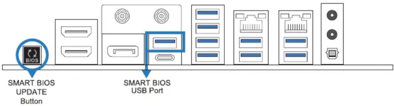
| Rear I/Os | 2 x WIFI Antenna Port2 x HDMI Port (HDMI2.1)1 x DP Port (DP2.1)1 x USB 4.0 Type-C Port with (DP1.4)9 x USB 3.2 (Gen2) Port1 x 5 Gigabit LAN port1 x 2.5 Gigabit LAN port2 x Audio Jack1 x S/PDIF_Out1 x SMART BIOS UPDATE Button1 x SMART BIOS USB Port |
| Internal I/Os | 4 x SATA III Connector (6Gb/s)1 x M.2 (E Key) Socket : Supports 2230 type Wi-Fi & Bluetooth module and Intel® GEN2 CNVi1 x USB 3.2 (Gen2x2) Type-C Header(each header supports 1 USB 3.2 (Gen2x2) Type-C ports)1 x USB 3.2 (Gen2) Header(each header supports 2 USB 3.2 (Gen2) ports)2 x USB 2.0 Header(each header supports 2 USB 2.0 ports)2 x 8-Pin Power Connector1 x 24-Pin Power Connector1 x CPU Fan Connector1 x CPU water cooling connector (CPU_OPT)4 x System Fan Connector1 x Front Panel Header1 x Front Audio Header1 x Internal Stereo Speaker Header1 x Clear CMOS Button1 x Power Switch Button1 x Reset Switch Button1 x COM Port Header1 x TPM Header1 x Thunderbolt Header4 x LED Header (5V)1 x LED Header (12V)1 x IO_LED Header* M.2 (E Key) Wi-Fi card is not provided |
| Form Factor ATX Form | Factor, 244 mm x 305 mm |
| OS Support | Windows 10(64bit) / Windows 11(64bit)* Biostar reserves the right to add or remove support for any OS with or without notice. |
1.3 Rear Panel Connectors
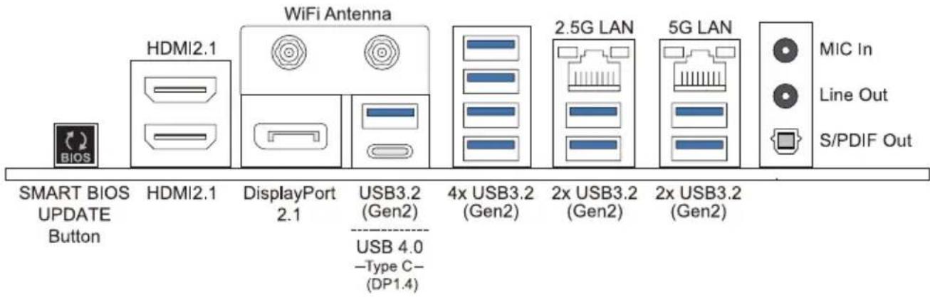
Note
» HDMI/ DP ports only work with an Intel® integrated Graphics Processor.
» Maximum resolution
HDMI:
7680 x 4320@120Hz, compliant with HDMI 2.1 (Bottom)
4096 x 2304@60Hz, compliant with HDMI 2.1 (Top)
DP:
7680 x 4320@120Hz, compliant with DP 2.1
» TYPE-C DP
4096 x 2304@120Hz, compliant with DP 1.4
The mainboard supports 4 onboard display outputs at same time and the display output configuration can be selected in Intel graphics driver utility.
» When using the front HD audio jack and plug in the headset, the rear sound will be automatically Disabled.
» The WiFi antenna port allows you to connect to the E Key module and use the WiFi & Bluetooth function.
1.4 Motherboard Layout
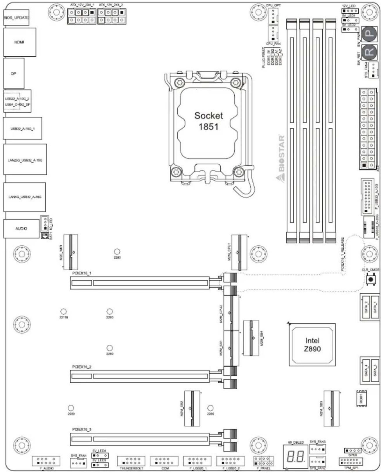
Note
» ■ represents the 1st pin.
Chapter 2: Hardware installation
2.1 Install Central Processing Unit (CPU)
Step 1: Locate the CPU socket on the motherboard
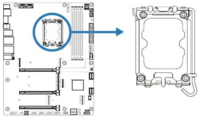
natural_image
Diagram of a computer motherboard showing a highlighted component and its exploded view (no text or labels)Note
» Remove pin cap before installation, and make good preservation for future use. When the CPU is removed, cover the pin cap on the empty socket to ensure pin legs won't be damaged.
» The motherboard might equip with two different types of pin cap. Please refer below instruction to remove the pin cap.
Step 2: Open ILM Lever and then load plate using finger tab
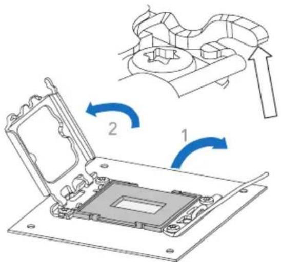
Step 3: Align and seat processor package on socket
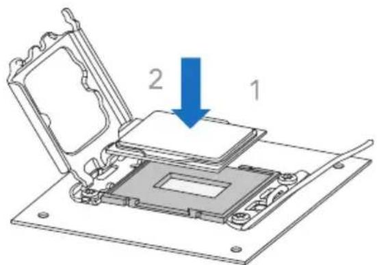
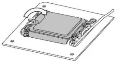
Step 4: Close the load plate
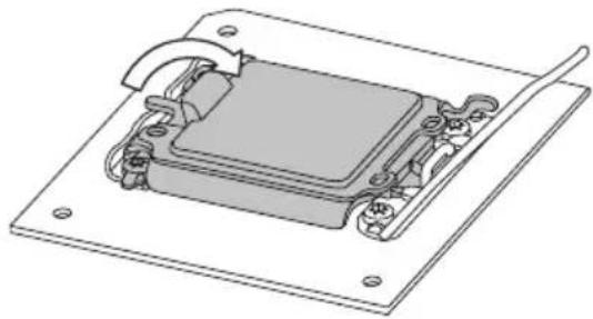
natural_image
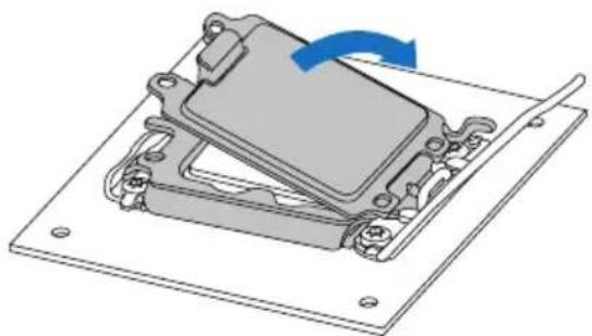
Technical illustration of a mechanical component with mounting flanges and internal components (no text or symbols)Step 5: Remove and save cover
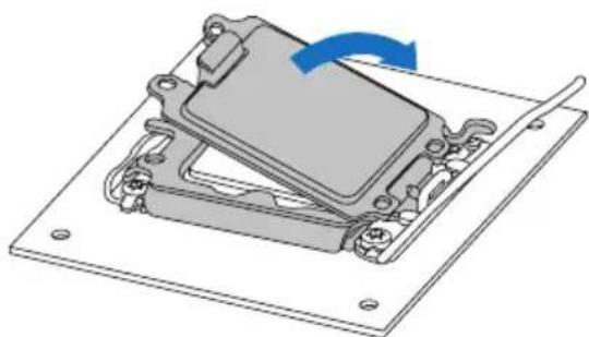
natural_image
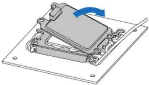
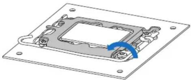
Mechanical assembly diagram showing a component being rotated with a blue arrow (no text or symbols present)Step 6: Close ILM Lever and latch
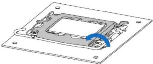
natural_image
3D diagram of a mechanical component with mounting flanges and a blue rotation arrow indicating rotational motion (no text or symbols)Note
» Ensure that you install the correct CPU designed for LGA1851 socket.
» The CPU fits only in one correct orientation. Do not force the CPU into the socket to prevent damaging the CPU.
2.2 Install a Heatsink
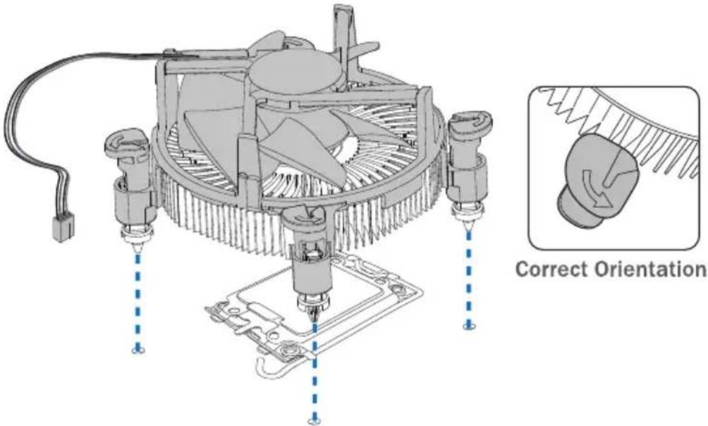
Step 1: Place the CPU fan assembly on top of the installed CPU and make sure that the four fasteners match the motherboard holes. Orient the assembly and make the fan cable is closest to the CPU fan connector.
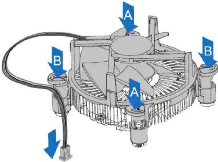
Step 2: Press down two fasteners at one time in a diagonal sequence to secure the CPU fan assembly in place. As each fastener locks into position a click should be heard.
Note
» Apply the thermal interface material on the CPU before heatsink installation, if necessary.
» Do not forget to connect the CPU fan connector.
» For proper installation, please kindly refer to the installation manual of your CPU heatsink.
2.3 Connect Cooling Fans
These fan headers support cooling-fans built in the computer. The fan cable and connector may be different according to the fan manufacturer.
CPU_FAN/ CPU_OPT: CPU Fan Header
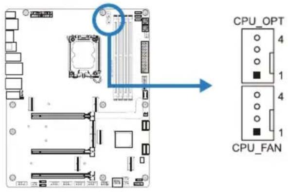
| Pin | Assignment |
| 1 | Ground |
| 2 | +12V |
| 3 | FAN RPM rate sense |
| 4 | AI Fan Control |
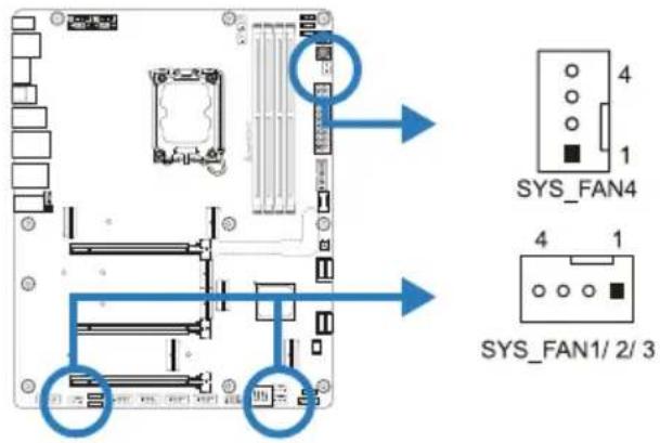
SYS_FAN1/ SYS_FAN2/ SYS_FAN3/ SYS_FAN4: System Fan Header
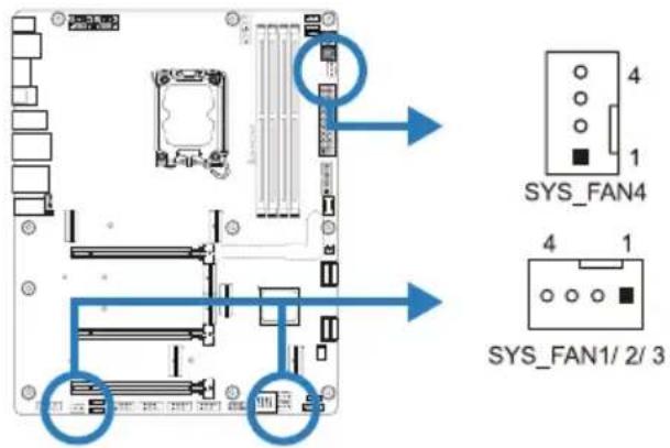
| Pin | Assignment |
| 1 | Ground |
| 2 | +12V |
| 3 | FAN RPM rate sense |
| 4 | AI Fan Control |
Note
» CPU_FAN, CPU_OPT, SYS_FAN1/2/3/4 support 4-pin and 3-pin head connectors. When connecting with wires onto connectors, please note that the red wire is the positive and should be connected to pin#2, and the black wire is Ground and should be connected to pin#1(GND).
» CPU Fan Header (CPU_OPT): Support water cooling fan and CPU fan.
2.4 Install System Memory
DDR5 Modules
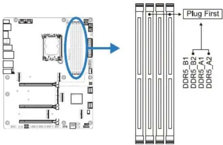
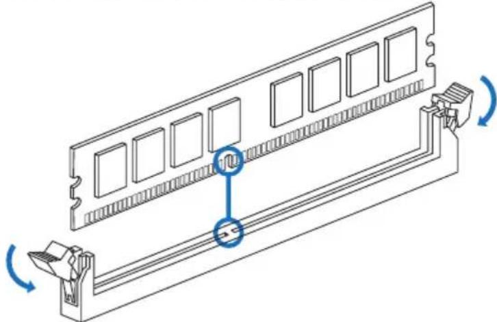
Step 1: Unlock a DIMM slot by pressing the retaining clips outward. Align a DIMM on the slot such that the notch on the DIMM matches the break on the slot.
natural_image
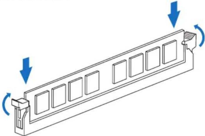
Technical line drawing of a computer RAM module with scroll wheel and scroll wheel (no text or symbols)Step 2: Insert the DIMM vertically and firmly into the slot until the retaining clips snap back in place and the DIMM is properly seated.
natural_image
Technical line drawing of a mechanical component with directional arrows indicating motion (no text or symbols)Note
» If the DIMM does not go in smoothly, do not force it. Pull it all the way out and try again.
Memory Capacity
| DIMM Socket Location DDR5 Module Total Memory Size | |
| DDR5_A1 8GB/16GB/24GB/32GB/48GB | Max is 192GB. |
| DDR5_A2 8GB/16GB/24GB/32GB/48GB | |
| DDR5_B1 8GB/16GB/24GB/32GB/48GB | |
| DDR5_B2 8GB/16GB/24GB/32GB/48GB |
Dual Channel Memory Installation
Please refer to the following requirements to activate Dual Channel function: Install memory module of the same density in pairs, shown in the table.
| Dual Channel Status DDR5_A1 DDR5_A2 DDR5_B1 DDR5_B2 | ||||
| Enabled X O X O | ||||
| Enabled O O O O | ||||
(O means memory installed, X means memory not installed.)
Note
» When installing more than one memory module, we recommend to use the same brand and capacity memory on this motherboard.
2.5 Expansion Slots
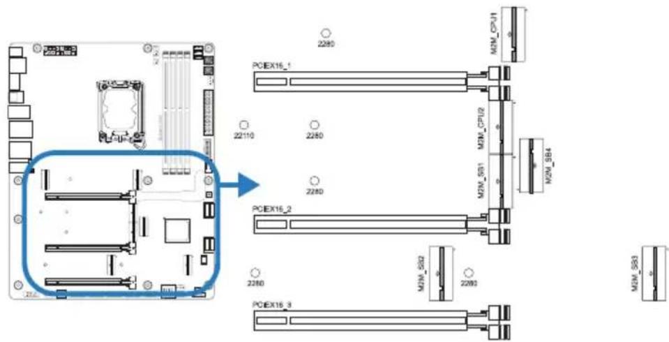
PCIEX16\_1: PCI-Express Gen5 x16 Slots (x16 or x8 mode)
• PCI-Express 5.0 compliant.
- The maximum bandwidth of the PCIe slot is 128GB/s.
PCIEX16\_2: PCI-Express Gen5 x16 Slots (x8 or x4 mode)
• PCI-Express 5.0 compliant.
• The maximum bandwidth of the PCIe slot is 64GB/s.
PCIEX16\_3: PCI-Express Gen5 x16 Slots (x4 mode)
• PCI-Express 5.0 compliant.
• The maximum bandwidth of the PCIe slot is 32GB/s.
M2M\_CPU\_1: M.2 (M Key) Socket
• Supports M.2 Type 2280 SSD module
• Supports PCIe 5.0x 4 (128Gb/s) - NVMe SSD
M2M\_CPU\_2: M.2 (M Key) Socket
• Supports M.2 Type 2280/22110 SSD module
• Supports PCIe 4.0x 4 (64Gb/s) - NVMe SSD
M2M\_SB1: M.2 (M Key) Socket
• Supports M.2 Type 2280 SSD module
• Supports PCIe 4.0x 4 (64Gb/s) - NVMe SSD
M2M\_SB2: M.2 (M Key) Socket
• Supports M.2 Type 2280 SSD module
• Supports PCIe 4.0x 4 (64Gb/s) - NVMe SSD
M2M\_SB3: M.2 (M Key) Socket
• Supports M.2 Type 2280 SSD module
• Supports PCIe 4.0x 4 (64Gb/s) - NVMe SSD
M2M\_SB4: M.2 (M Key) Socket
• Supports M.2 Type 2280 SSD module
• Supports PCIe 4.0x 4 (64Gb/s) - NVMe SSD
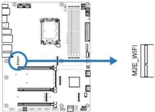
M2E\_WIFI: M.2 (E Key) Socket (M.2 (E Key) Wi-Fi card is not provided)
• Support M.2 socket 2230 type module.
- Supports WiFi/ Bluetooth module and Intel® CNVi (Integrated WiFi/ BT).
Install an Expansion Card
You can install your expansion card by following steps:
- Read the related expansion card's instruction document before install the expansion card into the computer.
- Remove your computer's chassis cover, screws and slot bracket from the computer.
- Place a card in the expansion slot and press down on the card until it is completely seated in the slot.
- Secure the card's metal bracket to the chassis back panel with a screw. (This step is only for installing a VGA card.).
- Replace your computer's chassis cover.
• Power on the computer, if necessary, change BIOS settings for the expansion card.
• Install related driver for the expansion card.
Note
» Please be note that you will need to use M2 type screwdriver if you want to install or uninstall the screw. It is recommended not to use a screwdriver that does not meet the specifications, otherwise the screw may be damaged.
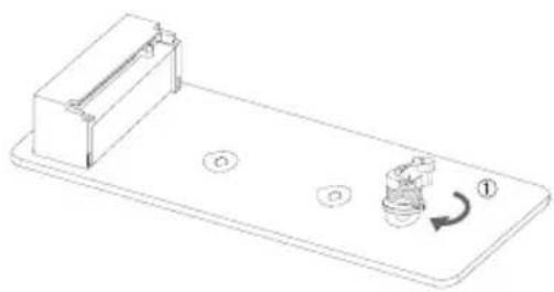
Installing M.2 Rotary Auto Anchor
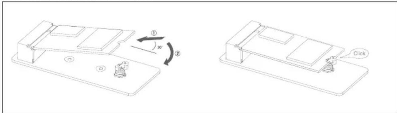
Installing an M.2 SSD card
- Insert the M.2 SSD into the M.2 slot at a 30-degree angle.
- Lower the M.2 SSD into position.
- Latch "Click" to secure M.2 SSD.
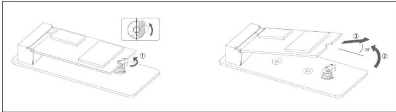
Remove the M.2 SSD card
- Unlatch the M.2 latch.
- Lift the M.2 SSD.
- Move the M.2 SSD out of the M.2 slot at a 30-degree angle.
natural_image
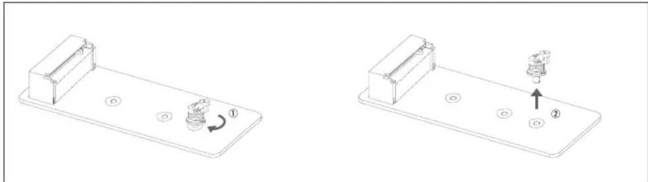
Technical line drawing of a mechanical assembly with numbered components and rotation indicators (no text or symbols)"M.2 Rotary Auto Anchor" replacement hole position: removal and installation
natural_image
Technical line drawing showing two mechanical components with circular holes and a valve, no text or symbols present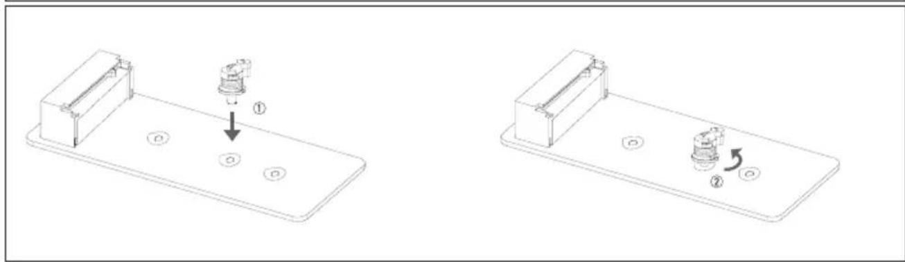
natural_image
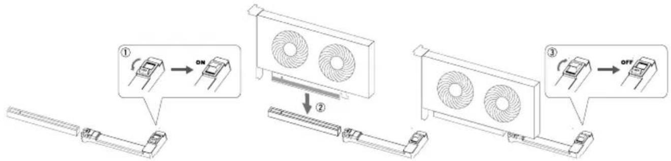
Technical line drawing showing two mechanical assembly states with labeled components (no text or symbols)PCIe Release Device
Installing an PCI Express card
- Press the switch button to "ON".
- Insert the PCI Express card into the PCIEX16_1 slot.
- Press the switch button to "OFF".
flowchart
graph TD
    A["① ON"] --> B["②"]
    B --> C["③ OFF"]
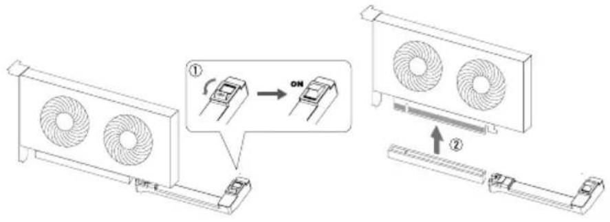
Remove the PCI Express card
- Press the switch button to "ON".
- Remove the PCI Express card.
2.6 Headers & Connectors
ATX: ATX Power Source Connector
For better compatibility, we recommend to use a standard ATX 24-pin power supply for this connector. Make sure to find the correct orientation before plugging the connector.
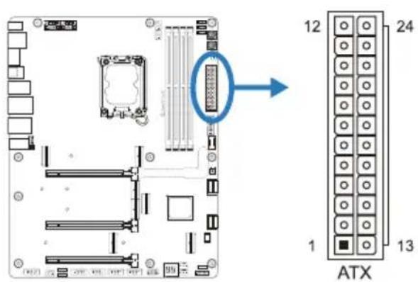
| Pin Assignment Pin Assignment | ||
| 13 +3.3V 1 +3.3V | ||
| 14 -12V 2 +3.3V | ||
| 15 Ground 3 Ground | ||
| 16 PS_ON 4 +5V | ||
| 17 Ground 5 Ground | ||
| 18 Ground 6 +5V | ||
| 19 Ground 7 Ground | ||
| 20 NC 8 PW_OK | ||
| 21 +5V 9 Standby Voltage+5V | ||
| 22 +5V 10 +12V | ||
| 23 +5V 11 +12V | ||
| 24 Ground 12 +3.3V | ||
ATX\_12V\_2X4\_1/ ATX\_12V\_2X4\_2: ATX Power Source Connector
The connector provides +12V to the CPU power circuit. If the CPU power plug is 4-pin, Please refer to the following methods to install:
- When Power Supply has two 8-pin CPU power plugs: please install at ATX_12V_2X4_1 and ATX_12V_2X4_2.
- When Power Supply has only one 8pin CPU power plug: please install it in ATX_12V_2X4_1 or ATX_12V_2X4_2.
- When the Power Supply has only a 4-pin CPU power plug: Please install on Pin 1-2-5-6 of ATX_12V_2X4_1 or Pin 1-2-5-6 of ATX_12V_2X4_2.
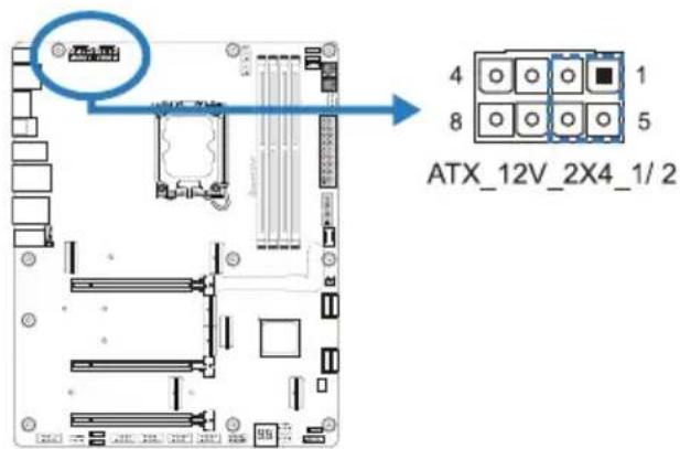
| Pin A | Assignment |
| 1 | +12V |
| 2 | +12V |
| 3 | +12V |
| 4 | +12V |
| 5 | Ground |
| 6 | Ground |
| 7 | Ground |
| 8 | Ground |
Note
» Before you power on the system, please make sure that both ATX, ATX_12V_2X4_1 and ATX_12V_2X4_2 connectors have been plugged-in.
» Insufficient power supplied to the system may result in instability or the peripherals not functioning properly. Use of a PSU with a higher power output is recommended when configuring a system with more power-consuming devices.
ATX Power Connection
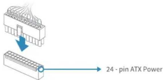
24-pin ATX Power: The main power supply connector is located along the edge of the board next to the DIMM slots. Firmly plug the power supply cable into the connector and make sure it is secure.
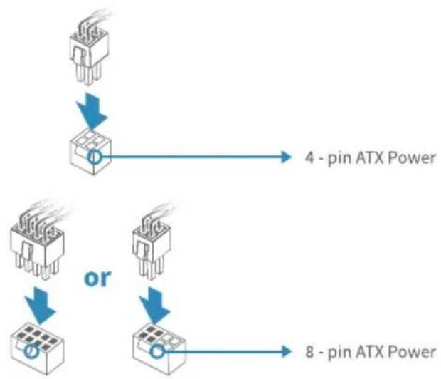
4 or 8-pin ATX Power: The 4 or 8-pin ATX 12V power connector is used to provide power to the CPU. Align the pins to the connector and press firmly until seated.
flowchart
graph TD
    A["Input 1: Pin 1"] --> B["Component 1"]
    C["Input 2: Pin 2"] --> D["Component 2"]
    E["Input 3: Pin 3"] --> F["Component 3"]
    G["Output 1: Pin 1"] --> H["Component 1"]
    I["Output 2: Pin 2"] --> J["Component 2"]
    K["Output 3: Pin 3"] --> L["Component 3"]
    M["Output 4: Pin 4"] --> N["Output 4"]
    O["Output 5: Pin 5"] --> P["Output 5"]
    Q["Output 6: Pin 6"] --> R["Output 6"]
    S["Output 7: Pin 7"] --> T["Output 7"]
    U["Output 8: Pin 8"] --> V["Output 8"]
F\_PANEL: Front Panel Header
This 10-pin header includes Power-on, Reset, HDD LED, Power LED connection.
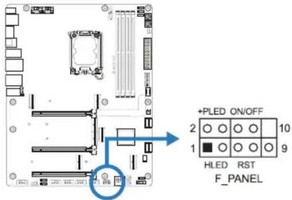
Please connect the chassis speaker to this header.
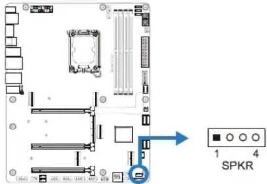
| Pin | Assignment |
| 1 +5V | |
| 2 N/A | |
| 3 N/A | |
| 4 Speaker | |
TPM\_SPI: Trusted Platform Module Header
This header allows you to store cryptographic keys that protect information.
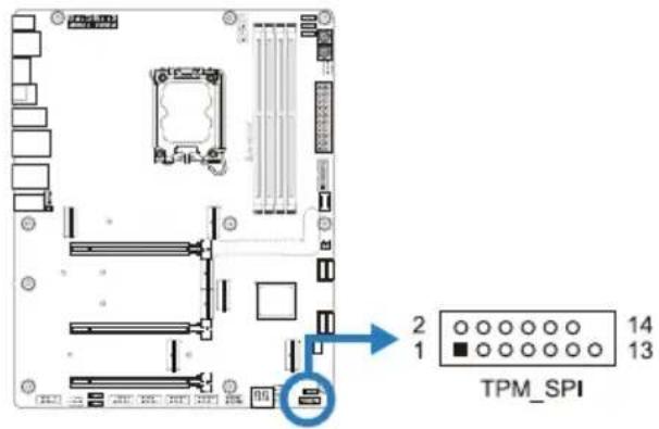
| Pin | Assignment | Pin | Assignment |
| 1 | +3.3V | 2 | SPI_PIRQ |
| 3 | TPM_RST# | 4 | TPM_CS |
| 5 | N/A | 6 | N/A |
| 7 | +3.3V | 8 | GND |
| 9 | N/A | 10 | SPI_CLK |
| 11 | SPI_MISO 12 | SPI_MOSI | |
| 13 | N/A 14 | KEY | |
SATA\_1/ SATA\_2/ SATA\_3/ SATA\_4: Serial ATA 6.0 Gb/s Connectors
These connectors connect to SATA hard disk drives via SATA cables.
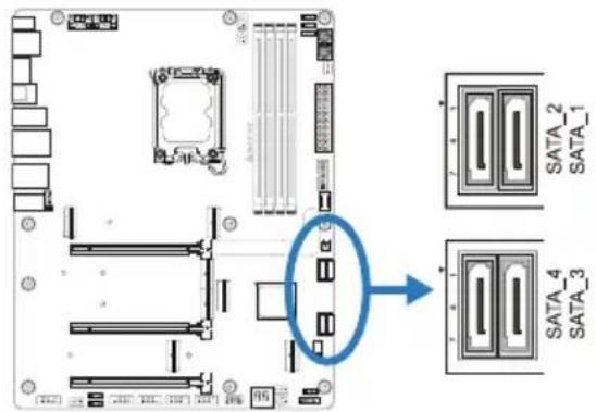
| Pin Assignment |
| 1 Ground |
| 2 TX+ |
| 3 TX- |
| 4 Ground |
| 5 RX- |
| 6 RX+ |
| 7 Ground |
F\_USB32\_C-20G: Header for USB 3.2 (Gen2x2) Ports at Front Panel
This USB type-C header allows user to add additional USB ports on the PC front panel, and also can be connected with a wide range of external peripherals.
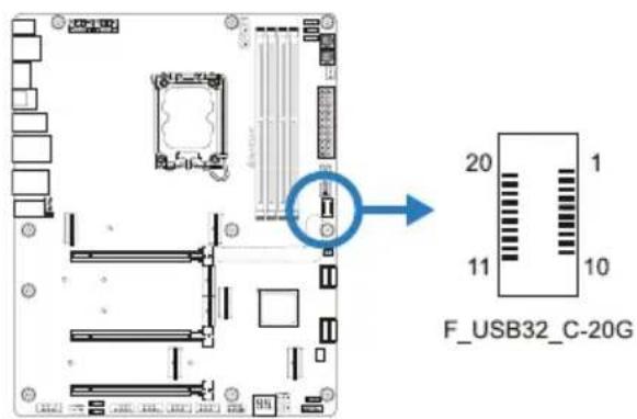
| Pin Assignment Pin Assignment | |
| 1 VBUS 11 VBUS | |
| 2 SSTX1+ 12 SSTX2+ | |
| 3 SSTX1- 13 SSTX2- | |
| 4 Ground 14 Ground | |
| 5 SSRX1+ 15 SSRX2+ | |
| 6 SSRX1- 16 SSRX2- | |
| 7 VBUS 17 Ground | |
| 8 CC1 18 D- | |
| 9 SBU 1 19 D+ | |
| 10 SBU2 20 CC2 | |
F\_USB32\_A-10G: Header for USB 3.2 (Gen2) Ports at Front Panel
This header allows user to add additional USB ports on the PC front panel, and also can be connected with a wide range of external peripherals.
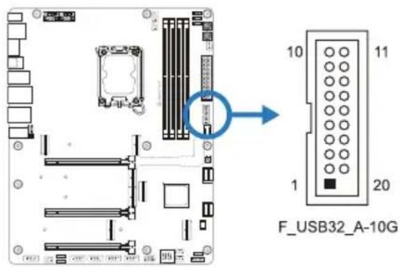
| Pin Assignment Pin Assignment | ||
| 1 VBUS0 11 D2+ | ||
| 2 SSRX1- 12 D2- | ||
| 3 SSRX1+ 13 Ground | ||
| 4 Ground 14 SSTX2+ | ||
| 5 SSTX1- 15 SSTX2- | ||
| 6 SSTX1+ 16 Ground | ||
| 7 Ground 17 SSRX2+ | ||
| 8 D1- 18 SSRX2- | ||
| 9 D1+ 19 VBUS1 | ||
| 10 ID 20 Key | ||
F\_USB20\_1/ F\_USB20\_2: Header for USB 2.0 Ports at Front Panel
This header allows user to add additional USB ports on the PC front panel, and also can be connected with a wide range of external peripherals.
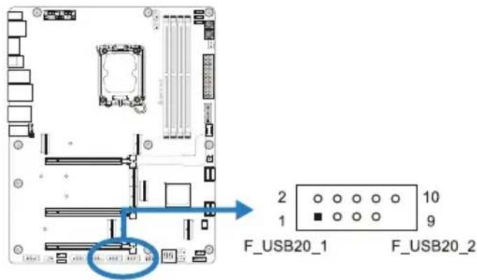
| Pin Assignment |
| 1 +5V (fused) |
| 2 +5V (fused) |
| 3 USB- |
| 4 USB- |
| 5 USB+ |
| 6 USB+ |
| 7 Ground |
| 8 Ground |
| 9 Key |
| 10 NC |
THUNDERBOLT: Thunderbolt Header
This header allows user to add additional Thunderbolt ports on the PC front panel, and also can be connected with a wide range of external peripherals.
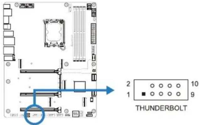
| Pin Assignment | |
| 1 Force Power | |
| 2 NC | |
| 3 CIO Plug Event | |
| 4 SMB_DATA_MAIN | |
| 5 SLP_S3_N | |
| 6 SMB_CLK_MAIN | |
| 7 SLP_S5_N | |
| 8 3V3_AIC_PD_INT# | |
| 9 GND | |
| 10 GND | |
F\_AUDIO: Front Panel Audio Header
This header allows user to connect the chassis-mount front panel audio I/O which supports HD.
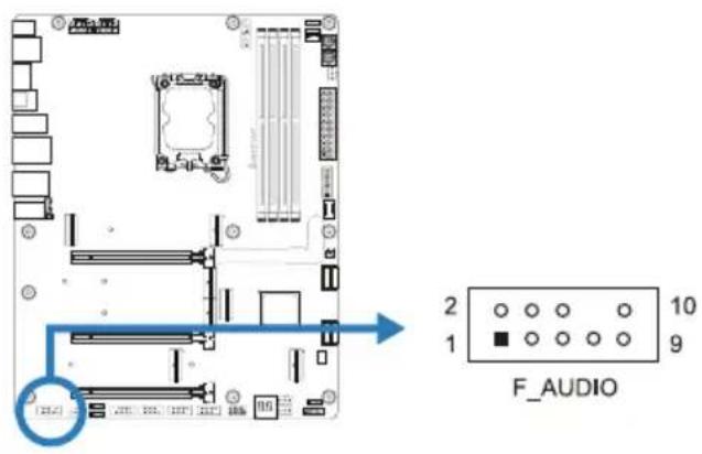
| HD Audio | |
| Pin Assignment | |
| 1 Mid | Left in |
| 2 Ground | |
| 3 Mid | Right in |
| 4 GPIO | |
| 5 Right line in | |
| 6 Jack Sense | |
| 7 Front Sense | |
| 8 Key | |
| 9 Left | line in |
| 10 Jack Sense | |
Note
» When using the front HD audio jack and plug in the headset, the rear sound will be automatically Disabled.
» It is recommended that you connect a high-definition front panel audio module to this connector to avail of the motherboard's high definition audio capability.
COM: Serial Port Header
The motherboard has a serial port header for connecting RS-232 Port.
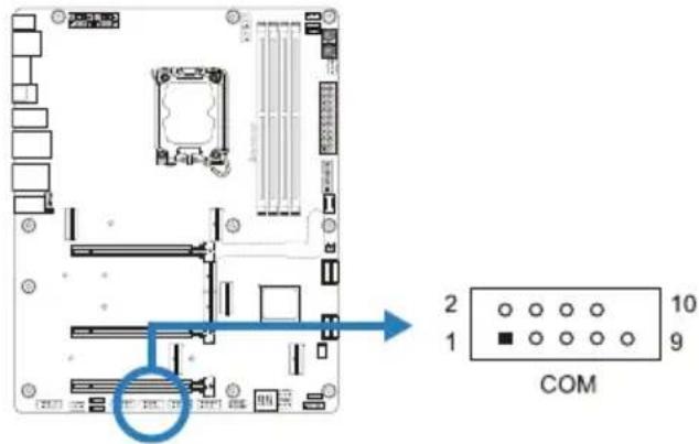
| Pin Assignment |
| 1 Carrier detect |
| 2 Received data |
| 3 Transmitted data |
| 4 Data terminal ready |
| 5 Signal ground |
| 6 Data set ready |
| 7 Request to send |
| 8 Clear to send |
| 9 Ring indicator |
| 10 Key |
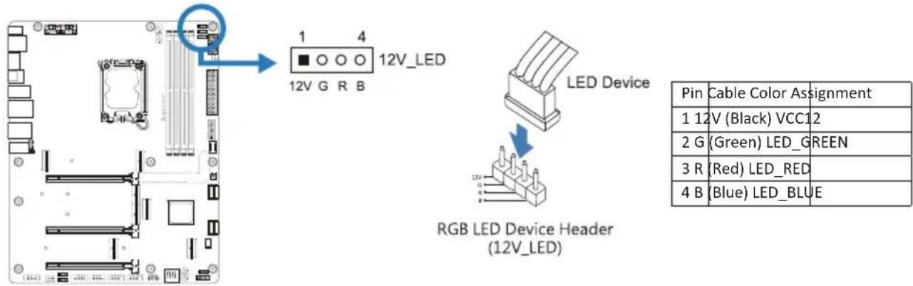
12V\_LED: RGB LED Header
This header providers 12V power and RGB control pins for RGB LED Device.
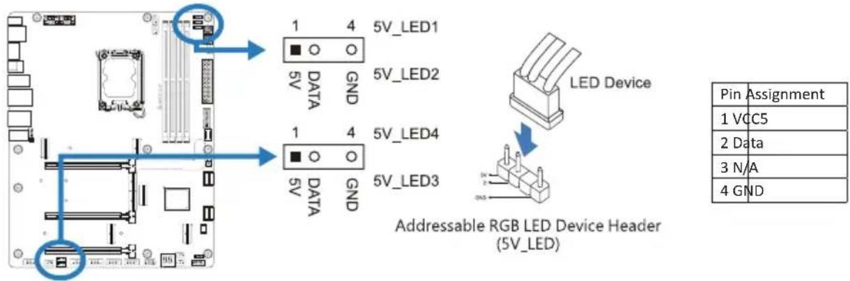
5V\_LED1/ 5V\_LED2/ 5V\_LED3/ 5V\_LED4: Addressable RGB LED Header
This header providers 5V power and Data control pins for RGB LED Device.
Note
» Ensure proper pin connecting to your LED device, wrong connection may damage your LED device or motherboard.
» The 12V_LED connector supports to 5050 RGB LED strips with the maximum power rating of 3A (12V).
» The 5V_LED connector supports up to 300 LEDs WS2818B individually Addressable RGB LED strips with the maximum power rating of 3A (5V).
» Please use the Vivid LED DJ software to control the LEDs. For detailed software setting information, refer to chapter 3.3.
2.7 Buttons, Indicators & LEDs
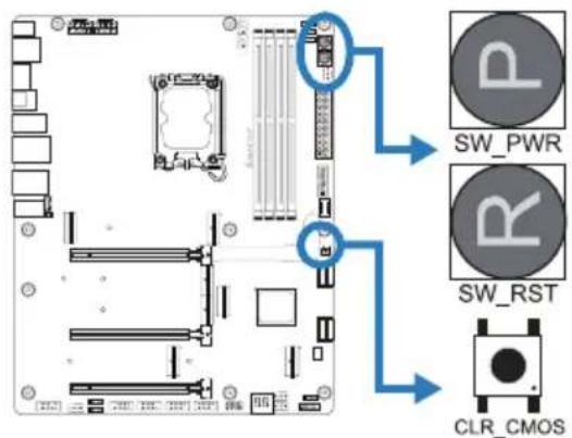
On-Board Buttons
Indicators
SW\_PWR:
Touch this button to turn-on/off the system.
SW\_RST:
Touch this button to reboot the system.
CLR\_CMOS:
Press the button 1\~2 Seconds to load the BIOS defaults.
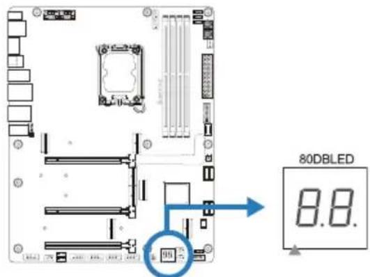
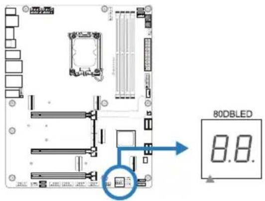
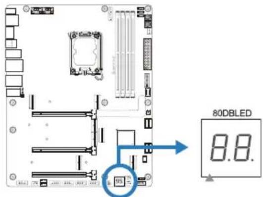
BIOS POST Code Indicator:
The indicator will show POST code while booting. Please refer to Chapter 4.3 for all the BIOS POST codes.
LEDs
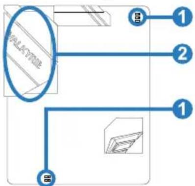
Below LEDs are controlled by AURORA program. Please refer to Chapter 3.3 for more detail software setting.
flowchart
graph TD
    A["输入图像"] --> B["步骤1"]
    A --> C["步骤2"]
    A --> D["步骤3"]
-
RGB LED Header(5V/12V)
-
ARMOR GEAR LEDs
Chapter 3: UEFI BIOS & Software
3.1 UEFI BIOS Setup
- The BIOS Setup program can be used to view and change the BIOS settings for the computer. The BIOS Setup program is accessed by pressing the
key after the Power-On Self-Test (POST) memory test begins and before the operating system boot begins. - For further information of setting up the UEFI BIOS, please refer to the UEFI BIOS Manual on our website.
3.2 BIOS Update
The BIOS can be updated using either of the following utilities:
- BIOSTAR BIO-Flasher: Using this utility, the BIOS can be updated from a file on a hard disk, a USB drive (a flash drive or a USB hard drive), or a CD-ROM.
- BIOSTAR BIOS Update Utility: It enables automated updating while in the Windows environment. Using this utility, the BIOS can be updated from a file on a hard disk, a USB drive (a flash drive or a USB hard drive), or a CD-ROM, or from the file location on the Web.
3.3 Motherboard BIOS Update
- Upload the newly update of BIOS into USB drive, change the file name to : CREATIVE. ROM (type each letter as exactly). For example: XXXXXXXX.BST to CREATIVE.ROM
- Connect the power into ATX 24PIN at motherboard, turn on AC power (only turn on Power supply unit, no need for power on)
- Insert USB Drive with the file name: CREATIVE.ROM into programmer(hardware)
- Press SMART BIOS Update button for 3\~5 seconds, LED will start flickering, when LED light is off, then the burning is completed.
BIOSTAR BIO-Flasher
Note
» This utility only allows storage device with FAT32/16 format and single partition.
» Shutting down or resetting the system while updating the BIOS will lead to system boot failure.
Updating BIOS with BIOSTAR BIO-Flasher
- Go to the website to download the latest BIOS file for the motherboard.
- Then, copy and save the BIOS file into a USB flash (pen) drive. (Only supported FAT/FAT32 format)
- Insert the USB pen drive that contains the BIOS file to the USB port.
-
Power on or reset the computer and then press
during the POST process. -
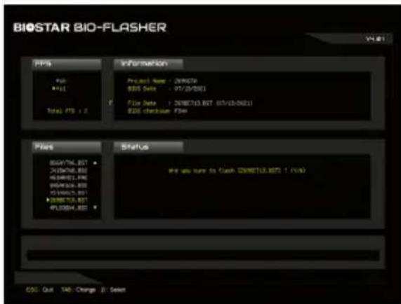
After entering the POST screen, the BIO-FLASHER utility pops out. Choose
to search for the BIOS file.
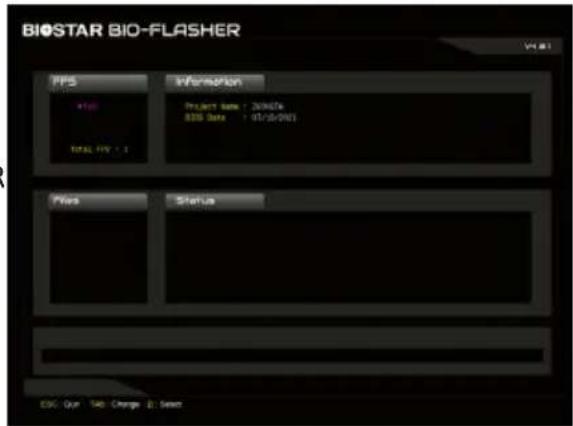
- Select the proper BIOS file, and a message asking if you are sure to flash the BIOS file. Click "Yes" to start updating BIOS.
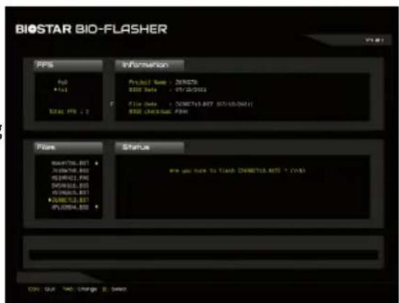
- A dialog pops out after BIOS flash is completed, asking you to restart the system. Press the
key to restart system.
![BIOSTAR BIO-FLASHER File File1 Total FTS + 2 Information Project Name: ZENZEN S350 Data: 97/03/2021 File: S350 XSS Light Size Mount System (VDD) Files Status XSS176.807 XJ04768.807 XQ48021.807 XPS48021.807 XPS48021.807 XPS48021.807 XPS48021.807 PL036H.807 Funding [XMM71L.BIT] ... use to Belize 111 use 100% COS: Out TAC: Change B: Select](/content/2026/05/910318/images/4922c0d76d534e30f6ed54362713d9a3e35560b8beda6a0e07801a99638f1ca2.jpg)
- While the system boots up and the full screen logo shows up, press
key to enter BIOS setup.
After entering the BIOS setup, please go to the
BIOS Update Utility (through the Internet)
- Installing BIOS Update Utility from the DVD Driver.
-
Please make sure the system is connected to the internet before using this function.
-
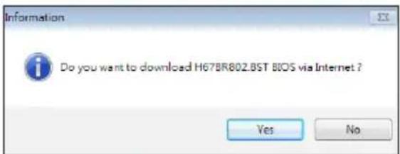
Launch BIOS Update Utility and click the "Online Update" button on the main screen.
-
An open dialog will show up to request your agreement to start the BIOS update. Click "Yes" to start the online update procedure.
-
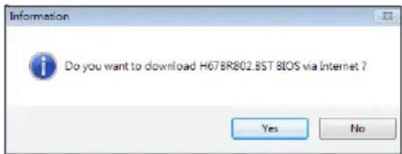
If there is a new BIOS version, the utility will ask you to download it. Click "Yes" to proceed.
-
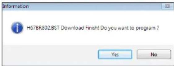
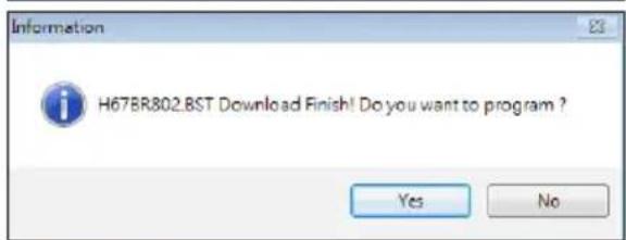
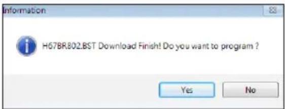
After the download is completed, you will be asked to program (update) the BIOS or not. Click "Yes" to proceed.
-
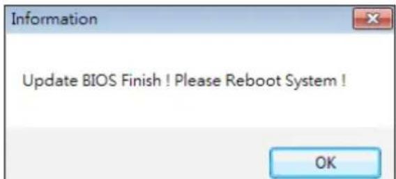
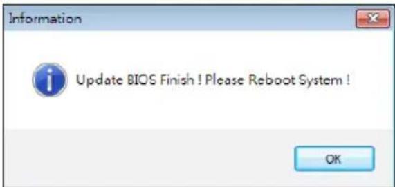
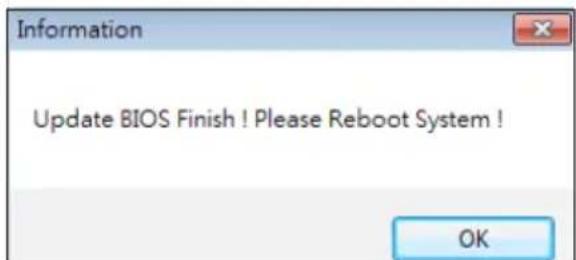
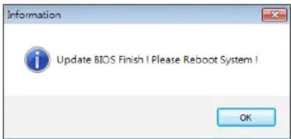
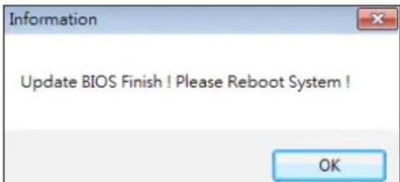
After the updating process is finished, you will be asked you to reboot the system. Click "OK" to reboot.
-
While the system boots up and the full screen logo shows up, press
key to enter BIOS setup.
After entering the BIOS setup, please go to the
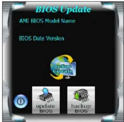
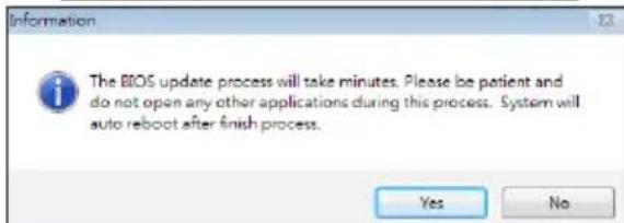
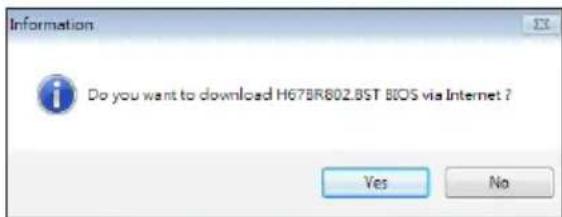
BIOS Update Utility (through a BIOS file)
- Installing BIOS Update Utility from the DVD Driver.
-
Download the proper BIOS from http://www.biostar.com.tw/
-
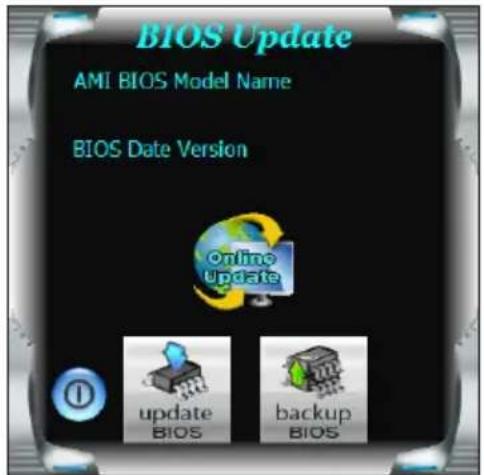
Launch BIOS Update Utility and click the "Update BIOS" button on the main screen.
-
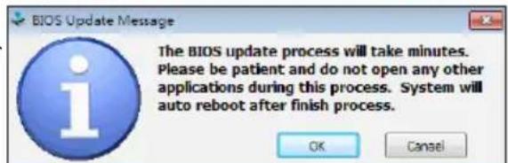
A warning message will show up to request your agreement to start the BIOS update. Click "OK" to start the update procedure.
-
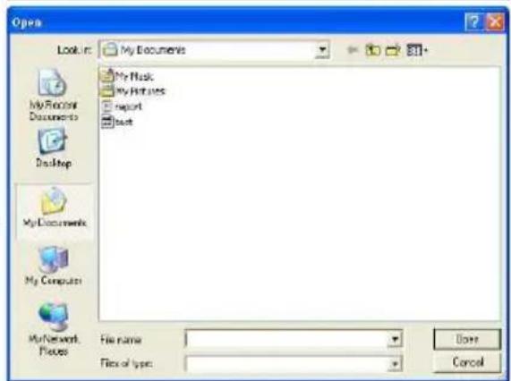
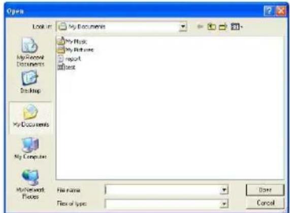
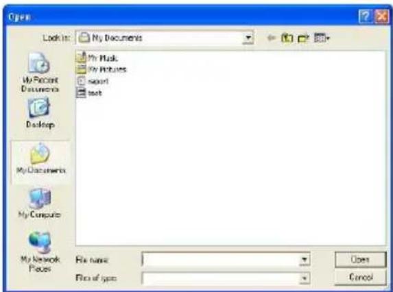
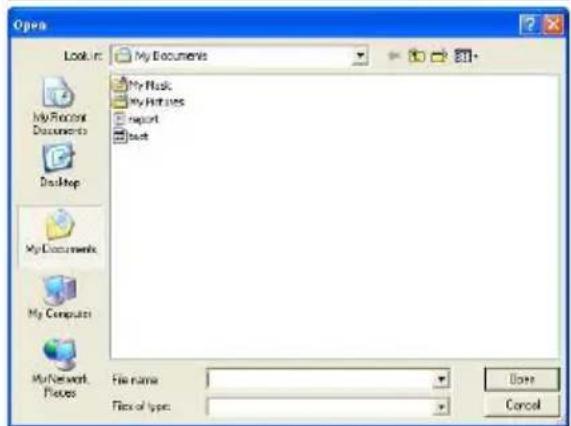
Choose the location for your BIOS file in the system. Please select the proper BIOS file, and then click on "Open". It will take several minutes, please be patient.
-
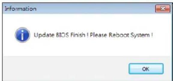
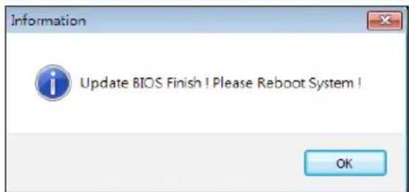
After the BIOS Update process is finished, click on "OK" to reboot the system.
-
While the system boots up and the full screen logo shows up, press
key to enter BIOS setup.
After entering the BIOS setup, please go to the
Backup BIOS
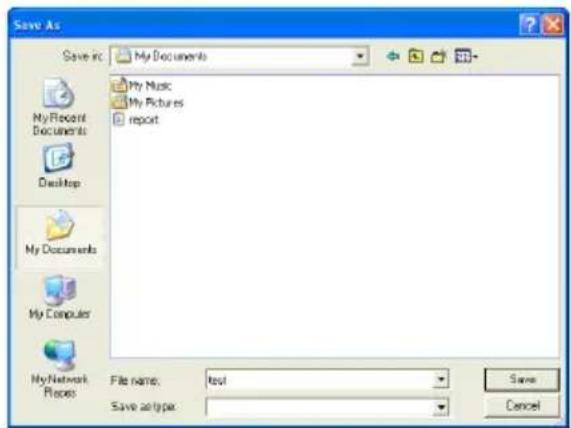
Click the Backup BIOS button on the main screen for the backup of BIOS, and select a proper location for your backup BIOS file in the system, and click "Save".
3.4 Software
Installing Software
- Insert the Setup DVD to the optical drive. The driver installation program would appear if the Auto-run function has been enabled.
- Select Software Installation, and then click on the respective software title.
- Follow the on-screen instructions to complete the installation.
Launching Software
After the installation process is completed, you will see the software icon showing on the desktop. Double-click the icon to launch it.
Note
» All the information and content about following software are subject to be changed without notice. For better performance, the software is being continuously updated.
» The information and pictures described below are for your reference only. The actual information and settings on board may be slightly different from this manual.
BIOScreen Utility
This utility allows you to personalize your boot logo easily. You can choose BMP as your boot logo so as to customize your computer.
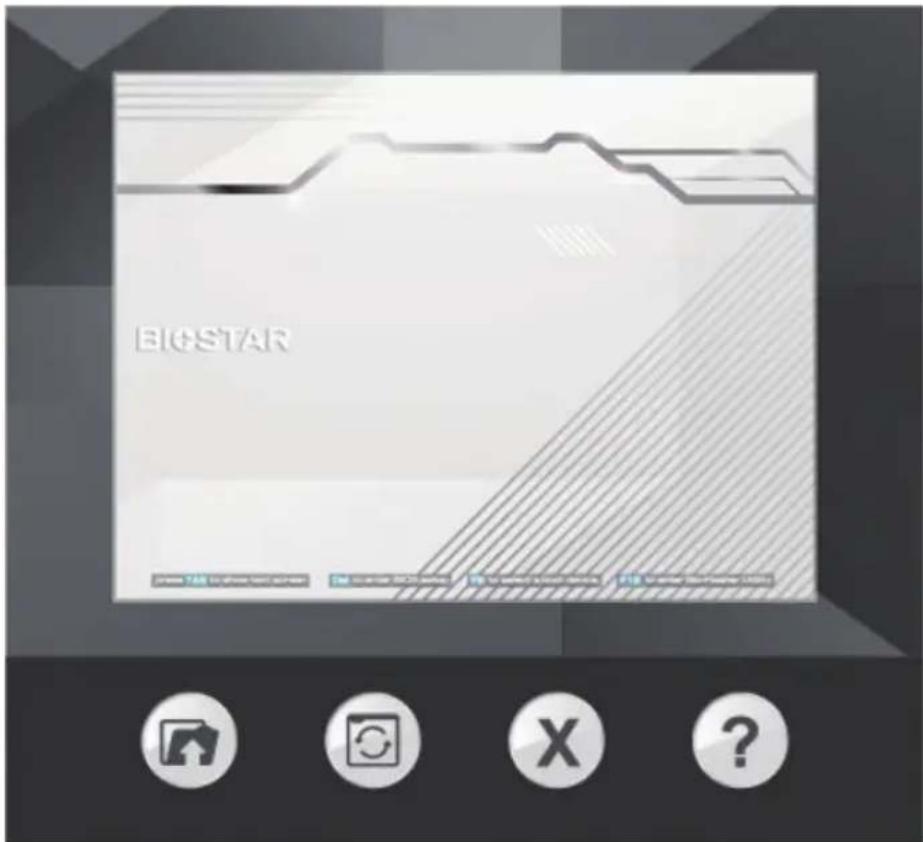
Please follow the step-by-step instructions below to update boot logo:
- Load Image: Choose the picture as the boot logo.
- Update Bios: Write the picture to BIOS Memory to complete the update.
- Close
- About
Vivid LED DJ
Vivid LED DJ can adjust your color scheme of ARMOR GEAR, RGB LED Device.
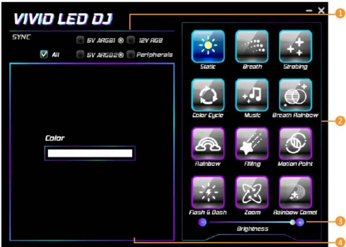
- LED Type: Select the LED lighting blocks.
• All : All LED illuminations.
• 12V RGB : The 12V LED illumination. (12V_LED Device)
- 5V ARGB1 / 5V ARGB2 : The 5V LED illumination. (5V_LED Device)
• Peripherals : The RGB LED illumination.
-
LED SPARKLE: Allows to you choose sparkle of the LEDs.
-
Static
- Breath
- Strobing
- Color Cycle
- Music
- Breath Rainbow
- Rainbow
- Filling
- Motion Point
- Flash & Dash
- Zoom
-
Rainbow Comet
-
Brightness: Allow to adjust brightness of the LEDs.
-
Color Palette: Allows to you choose specific color of the LEDs.
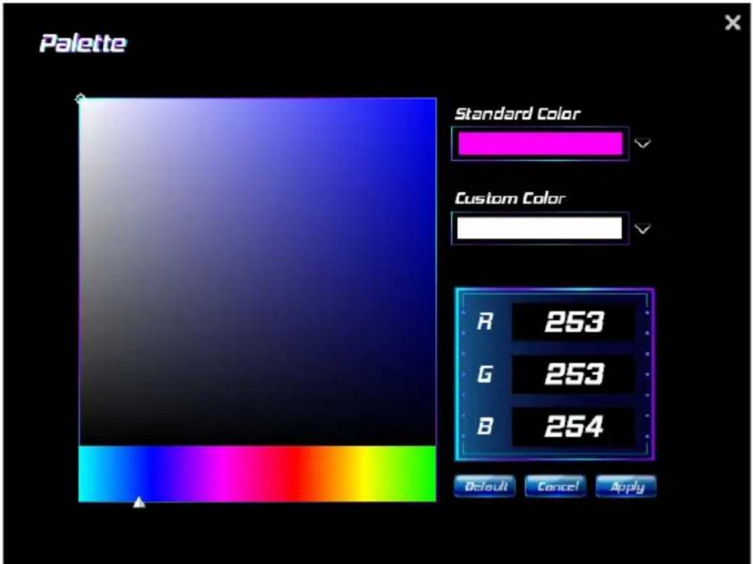
- Palette: Allows to you choose specific color of the LEDs.
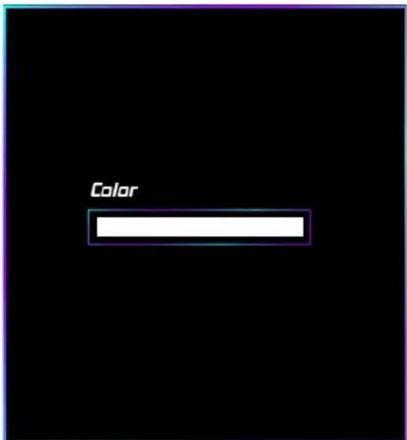
• Color: Allows to you choose color.
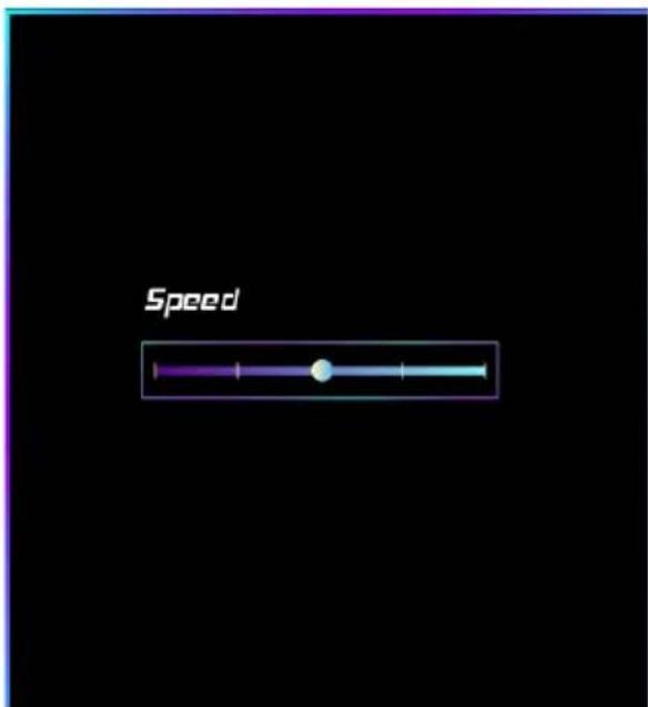
• Speed: Allows to you adjust speed.
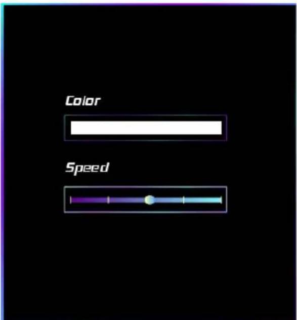
• Color: Allows to you choose color.
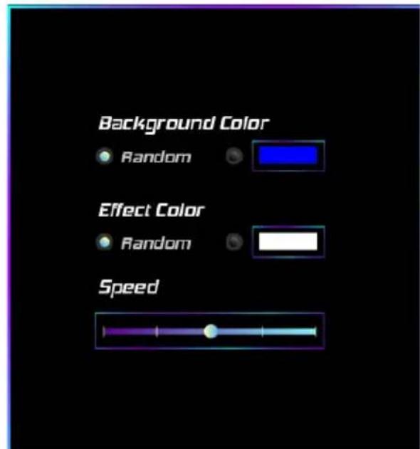
• Speed: Allows to you adjust speed.
• Color: Allows to you choose color.
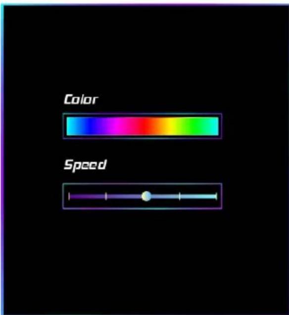
• Speed: Allows to you adjust speed.
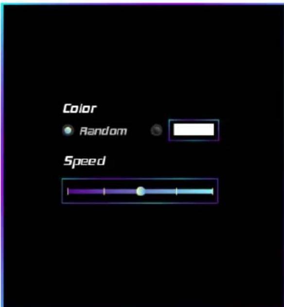
- Random: LEDs will Automatically change the Color Palette.
VALKYRIE AURORA Utility
VALKYRIE AURORA Utility is an easy-to-use program that integrates several BIOSTAR utilities and allows users to configure these utilities simultaneously and seamlessly.
Note
» Menu contents of VALKYRIE AURORA Utility will be different slightly, depending on different motherboard of users' computers.
» When the software is installed or removed, restart your computer.
System Information
This System Information tab provides you an overview of the basic system information.
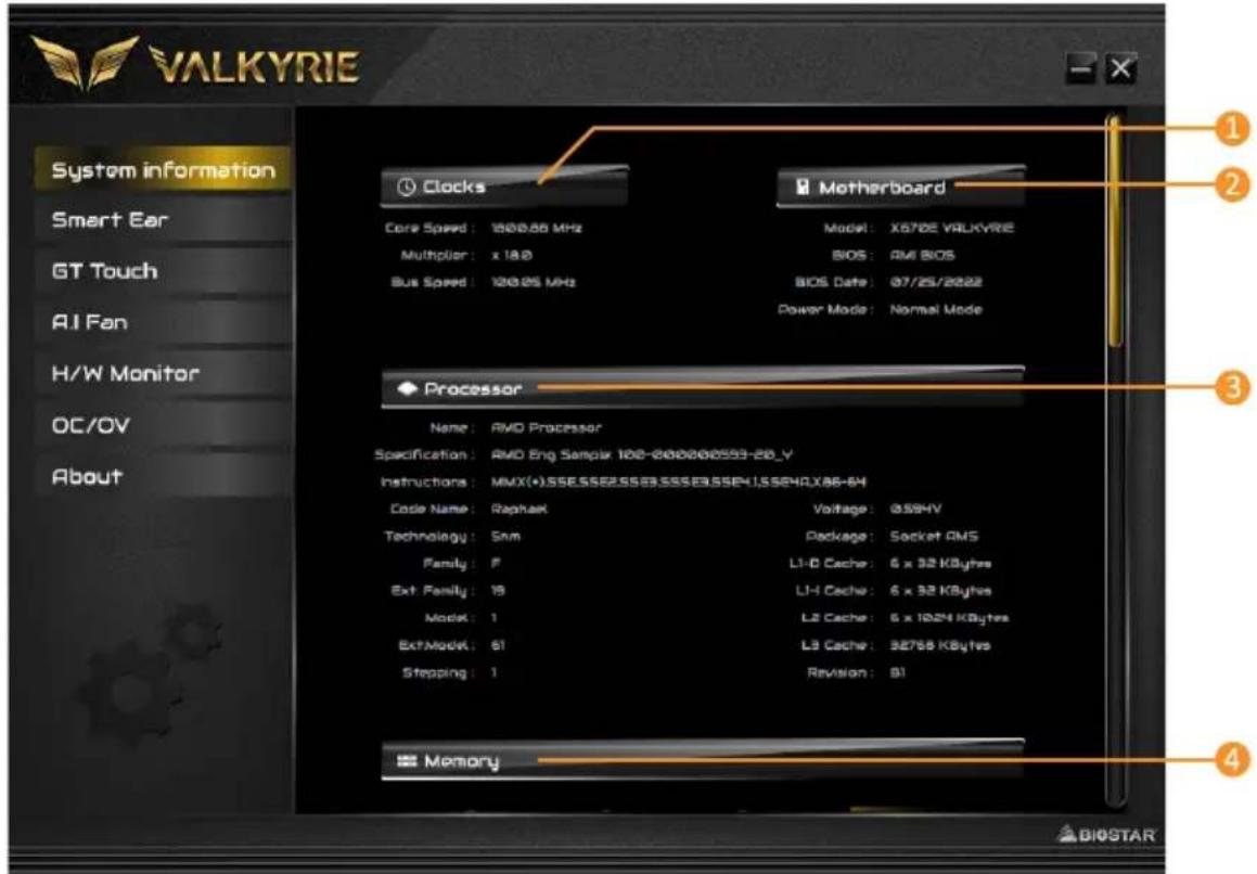
- Clocks: Shows core speed, multiplier and bus speed.
- Motherboard: Shows motherboard information.
- Processor: Shows CPU information.
- Memory: Shows memory information.
» Click on different memory slot buttons to get the memory information.
SmartEAR
Smart EAR allows you to control system volume and adjust impedance setting (Low/High Gain) to optimize your headphone performance. You can easily enjoy high-quality and awesome sound.
Requirements:
- A chassis with front audio output jacks
- An earphone or a headphone
- Windows 11 (64bit)/ 10 (64bit) operation system
Installation Guide:
- Make sure the front audio cable of the chassis connected to the front audio header of the motherboard properly.
- Install the VALKYRIE AURORA Utility program from the driver DVD.
- Connect the earphone or headphone to the front audio jack of the chassis or audio lineout port of rear I/Os.
» If you want to use an AC'97 front audio output cable, please disable the "Front Panel Jack Detection" setting. This setting can be found via O.S. Audio Utility.
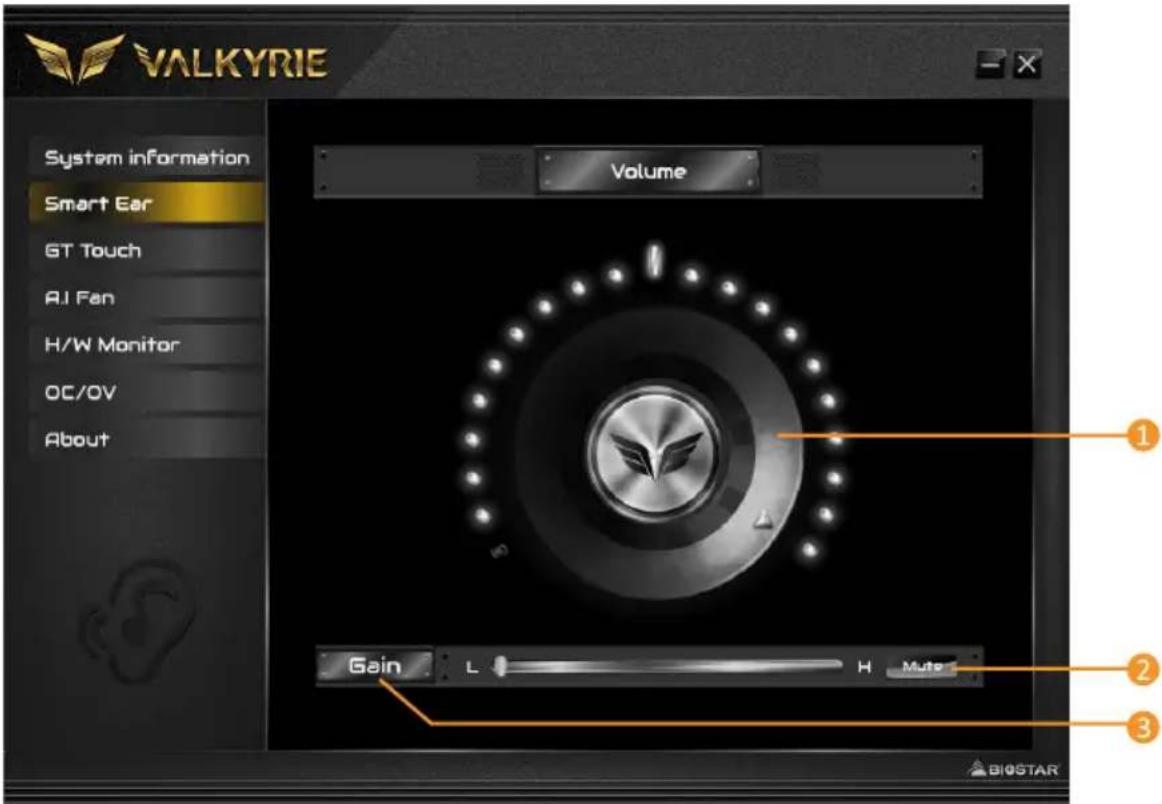
- Volume Control Knob: The volume can be finely adjusted by turning the knob either clockwise or anti-clockwise to increase or decrease system volume accordingly.
- Mute: To disable system sound.
- High/Low Gain Switch: Keep the gain switch to low for low impedance headphone and set to high for high impedance headphone.
GT Touch
GT Touch allows you to adjust Normal, ECO and Sport mode when running VALKYRIE AURORA Utility program in Windows environment.
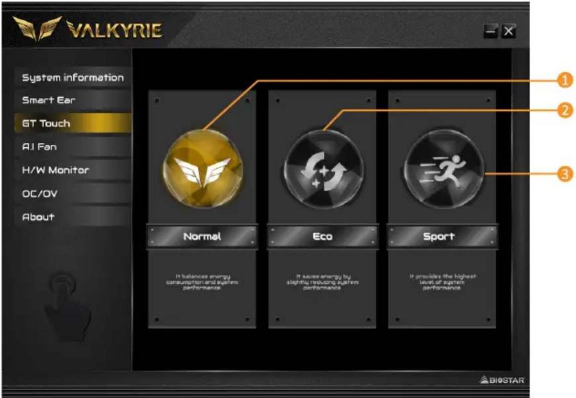
- Normal Mode: It balances energy consumption and system performance.
- ECO Mode: It saves energy by slightly reducing system performance.
- Sport Mode: It provides the highest level of system performance.
A.I Fan
A.I FAN utility smartly allows PC users to have more customizability of fan operating modes and automatically detects different temperatures to make fan operating at defined speed for optimal cooling performance.
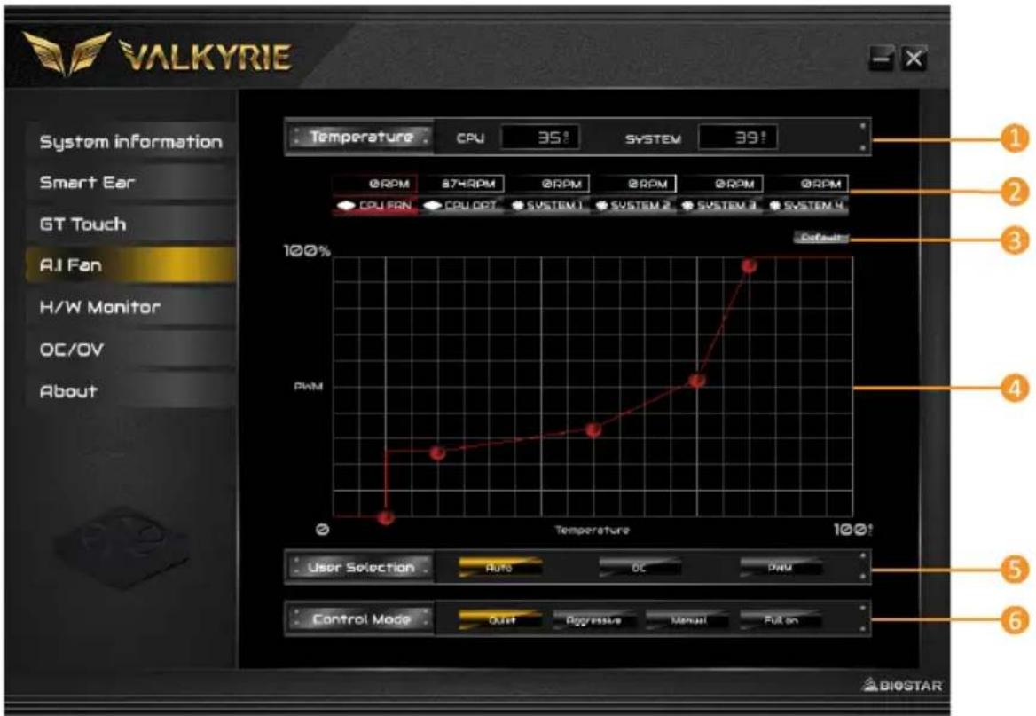
- Temperature: Shows the current CPU and system temperature.
- CPU FAN/ CPU OPT RPM & SYSTEM1/2/3/4 RPM: Click button to set the status value of CPU and system fan.
» Display items, please focus on the actual motherboard. - Default: Restore defaults your changes value of a single item.
- PWM/ Temperature Panel: According to the fan PWM value corresponding to CPU and system temperature to adjust the fan speed.
» Allows you to adjust according to your preferences. - User Selection: Sets the fan property controls the actual selection operation.
• Auto: Allows you to adjust the Automatic detection Mode.
• DC: Allows you to adjust the Direct Current (DC) Mode. - PWM: Allows you to adjust the Pulse Width Modulation (PWM) Mode.
- Control Mode: Allows you to control mode of the fans.
- Quiet: Enable Quiet mode.
- Aggressive: Enable Aggressive mode.
- Manual: Enable Manual mode.
• Full on: Enable Full On mode.
H/W Monitor
The HW Monitor tab allows you to monitor hardware voltage, fan speed, and temperature.
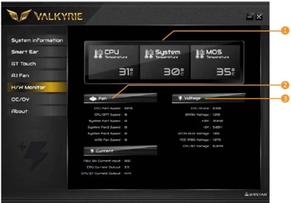
- CPU Temperature/ System Temperature: Shows the current CPU and system temperature.
- Fan: Shows the current fans' speed.
- Voltage: Shows the current voltages of CPU and memory.
oc/ov
The OC/OV tab allows you to save or load the OC/OV setting profiles, change system frequency and voltage settings.
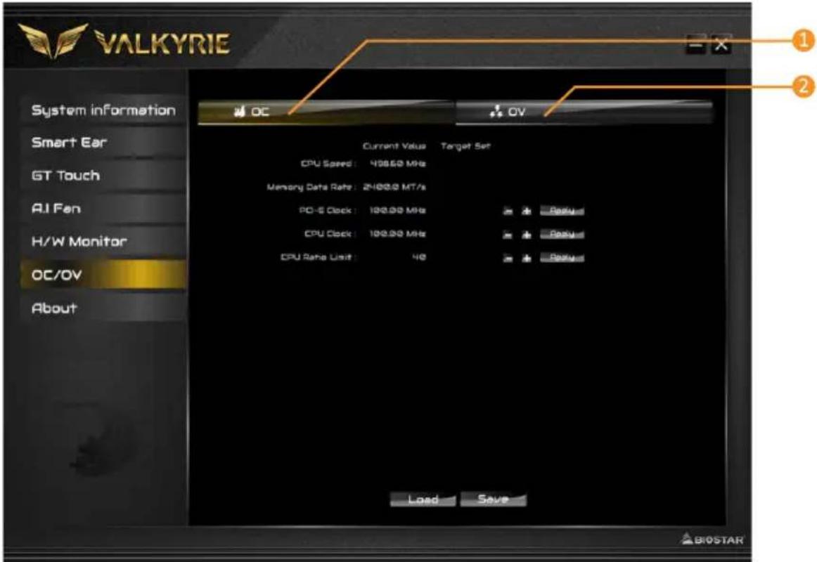
- OC: Allows you to adjust overclocking profile values.
- OV: Allows you to adjust voltage profile values.
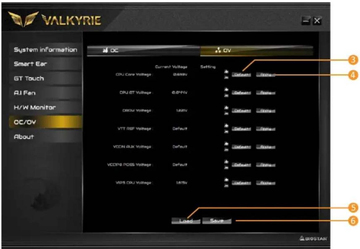
- Default: Restore defaults your changes.
- Apply: Apply your changes.
- Load: Load the profile values from the file.
- Save: Store the profile values for future use.
Note
» Not all types of CPU perform above overclock setting ideally; the difference will be based on the selected CPU model.
Overclock is an optional process, but not a "must-do" process; it is not recommended for inexperienced users. Therefore, we will not be responsible for any hardware damage which may be caused by overclocking. We also would not guarantee any overclocking performance.
About
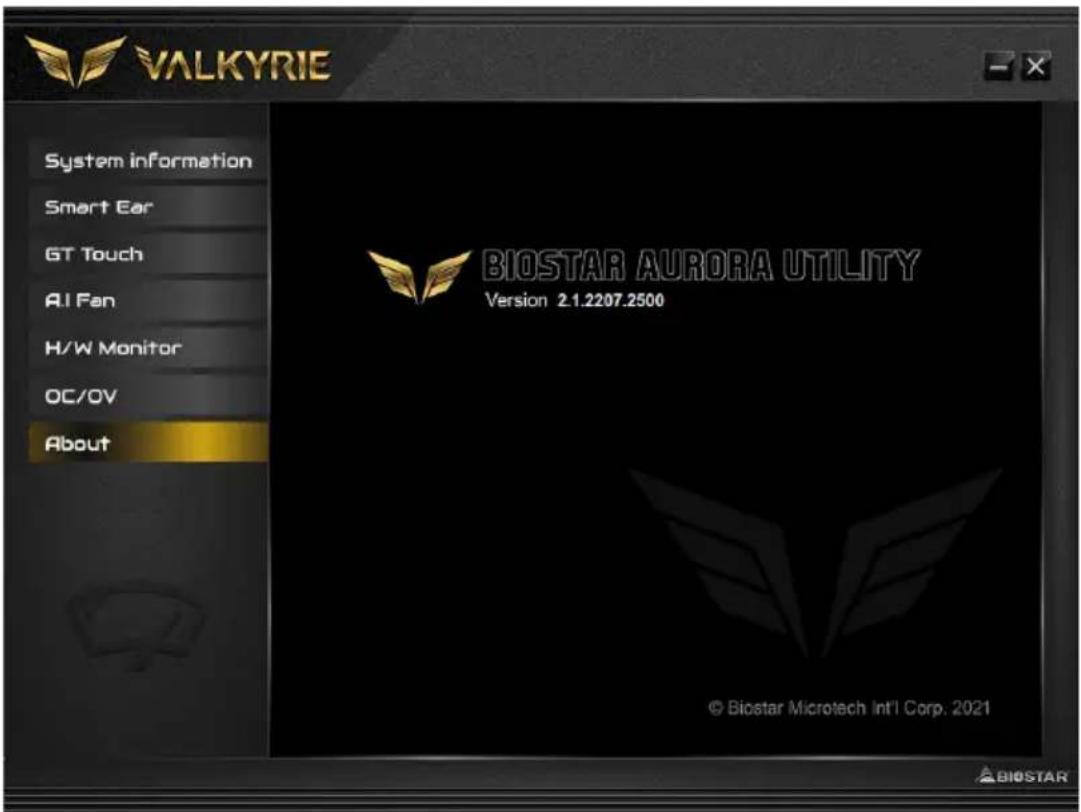
The About menu to display the VALKYRIE AURORA Utility version information.
Chapter 4: Useful help
4.1 Auto Installer
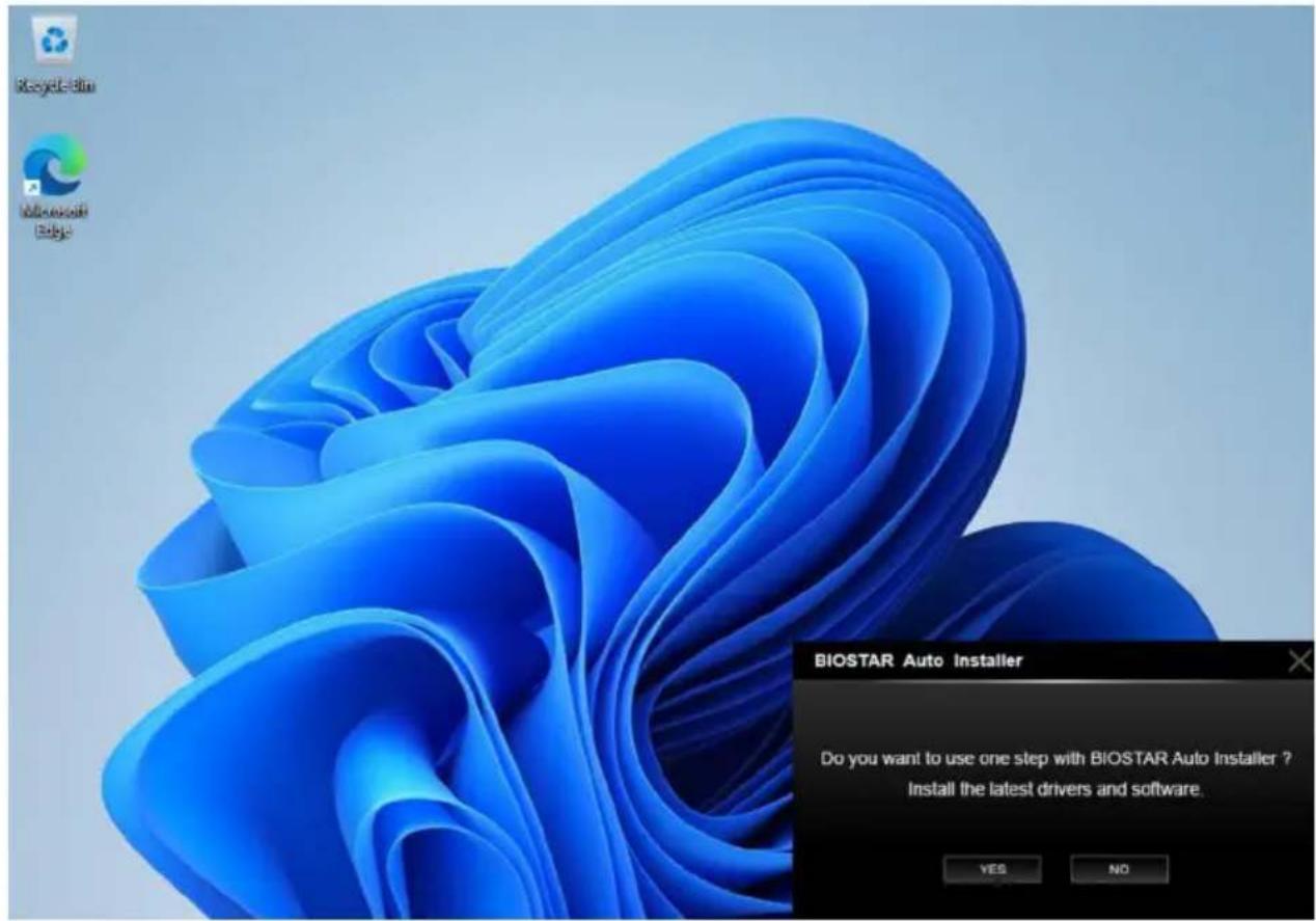
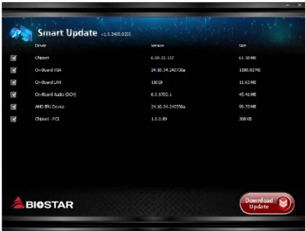
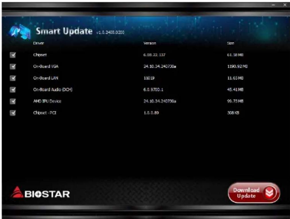
After connecting to the Internet and booting, BIOSTAR AUTO Installer will be displayed in the lower right corner. (Press "Yes")
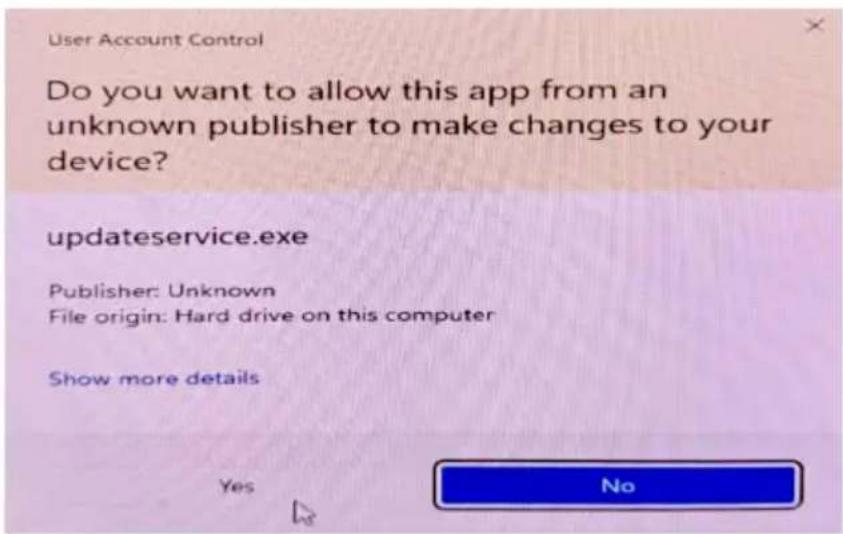
Press "Yes"
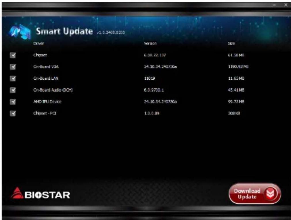
Press Lower right "Download Update"
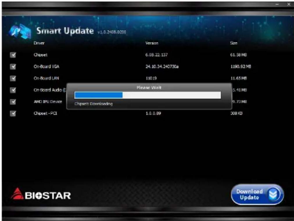
Wait download process is complete.
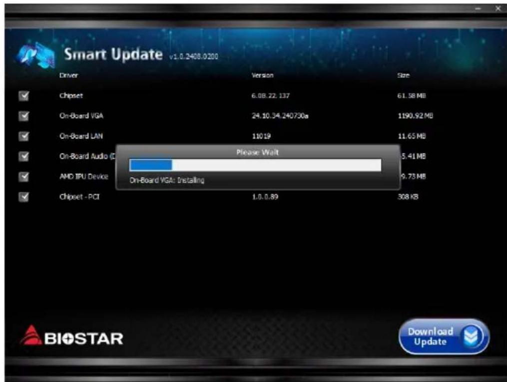
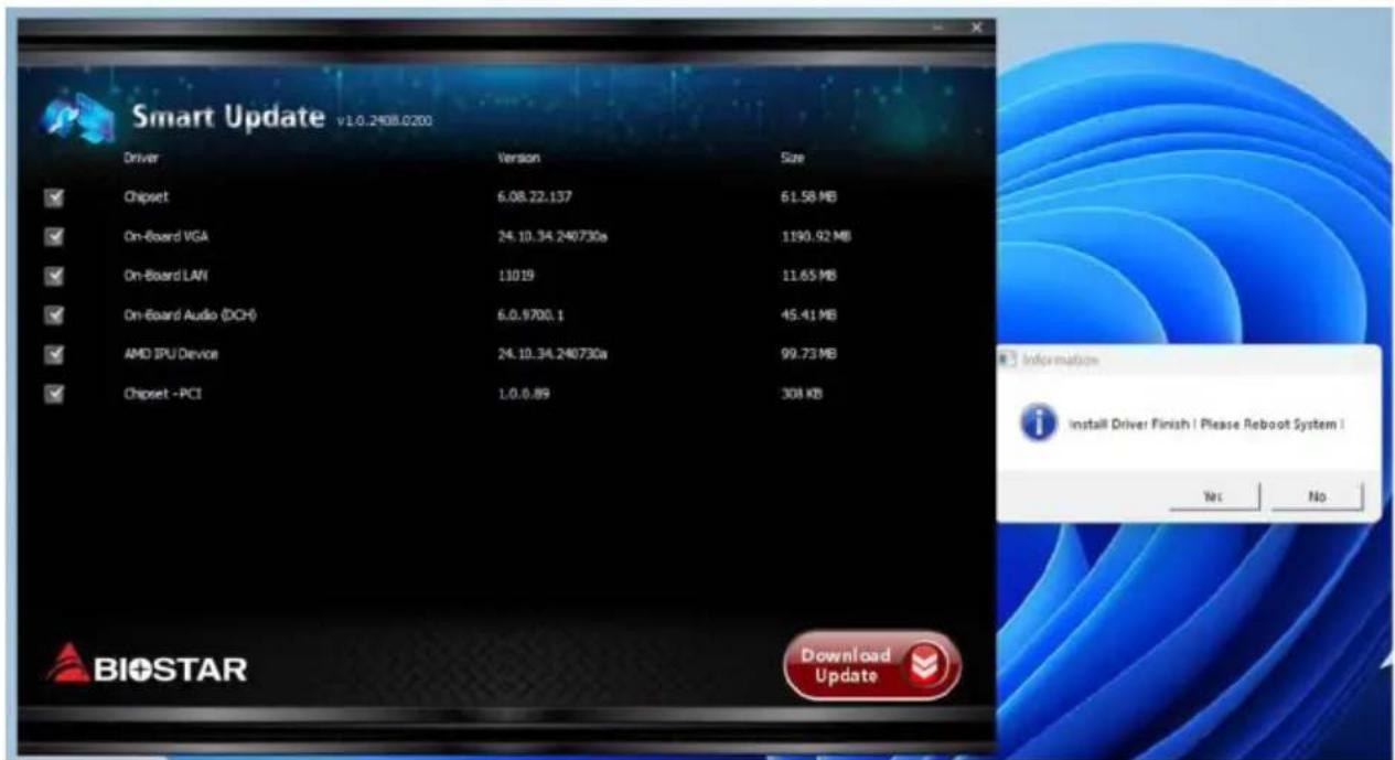
After the download and installation are complete, please restart your system.
4.2 RAID Functions
RAID Definitions
flowchart
graph TD
    A["RAID 0 striping"] --> B["Block 1"]
    A --> C["Block 2"]
    A --> D["Block 3"]
    A --> E["Block 4"]
    A --> F["Block 5"]
    A --> G["Disk 1"]
    A --> H["Disk 2"]
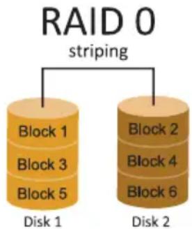
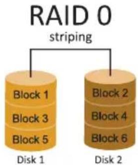
In a RAID 0 system data are split up in blocks that get written across all the drives in the array. By using multiple disks (at least 2) at the same time, this offers superior I/O performance. This performance can be enhanced further by using multiple controllers, ideally one controller per disk.
Features and Benefits
- Drives: Minimum 2, and maximum is up to 6 or 8. Depending on the platform.
- Uses: Intended for non-critical data requiring high data throughput, or any environment that does not require fault tolerance.
- Benefits: provides increased data throughput, especially for large files. No capacity loss penalty for parity.
- Drawbacks: Does not deliver any fault tolerance. If any drive in the array fails, all data is lost.
- Fault Tolerance: No.
• Total Capacity: (Minimal. HDD Capacity) x (Connected HDDs Amount)
flowchart
graph TD
    A["Block 1\nBlock 2\nBlock 3\nDisk 1"] --> B["Block 1\nBlock 2\nBlock 3"]
    C["Block 1\nBlock 2\nBlock 3\nDisk 2"] --> D["Block 1\nBlock 2\nBlock 3"]
    E["RAID 1 mirroring"] --> F["Block 1\nBlock 2\nBlock 3"]
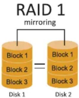
Data are stored twice by writing them to both the data disk (or set of data disks) and a mirror disk (or set of disks). If a disk fails, the controller uses either the data drive or the mirror drive for data recovery and continues operation. You need at least 2 disks for a RAID 1 array.
Features and Benefits
- Drives: Minimum 2, and maximum is 2.
- Uses: RAID 1 is ideal for small databases or any other application that requires fault tolerance and minimal capacity.
- Benefits: Provides 100% data redundancy. Should one drive fail, the controller switches to the other drive.
- Drawbacks: Requires 2 drives for the storage space of one drive. Performance is impaired during drive rebuilds.
- Fault Tolerance: Yes.
RAID 10 (1+0)
flowchart
graph TD
    A["Block 1\nBlock 3\nBlock 5\nDisk 1"] --> B["Block 1\nBlock 3\nBlock 5"]
    C["Block 2\nBlock 4\nBlock 6\nDisk 3"] --> D["Block 2\nBlock 4\nBlock 6"]
    E["Block 2\nBlock 4\nBlock 6"] --> F["Block 2\nBlock 4\nBlock 6"]
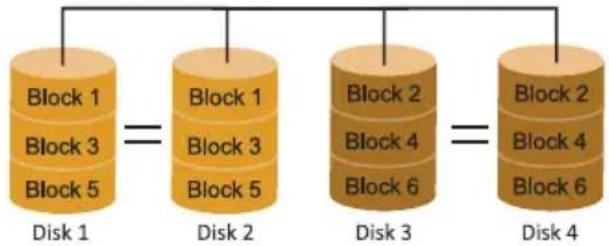
RAID 10 combines the advantages (and disadvantages) of RAID 0 and RAID 1 in one single system. It provides security by mirroring all data on a secondary set of disks (disk 3 and 4 in the drawing below) while using striping across each set of disks to speed up data transfers.
Features and Benefits
- Drives: Minimum 4, and maximum is 6 or 8, depending on the platform.
- Benefits: Optimizes for both fault tolerance and performance, allowing for automatic redundancy. May be simultaneously used with other RAID levels in an array, and allows for spare disks.
- Drawbacks: Requires twice the available disk space for data redundancy, the same as RAID level 1.
- Fault Tolerance: Yes.
RAID 5
parity across disks
flowchart
graph TD
    A["DATA1"] --> B["Data 1"]
    C["DATA3"] --> D["Data 1"]
    E["PARITY"] --> F["Data 1"]
    G["DATA7"] --> H["Data 1"]
    I["DATA9"] --> J["Data 1"]
    K["PARITY"] --> L["Data 1"]
    B --> M["Data 2"]
    D --> N["Data 2"]
    F --> O["Data 2"]
    H --> P["Data 2"]
    J --> Q["Data 2"]
    L --> R["Data 2"]
    N --> S["Data 2"]
    O --> T["Data 2"]
    P --> U["Data 2"]
    Q --> V["Data 2"]
    R --> W["Data 2"]
    S --> X["Data 2"]
    T --> Y["Data 2"]
    U --> Z["Data 2"]
    V --> AA["Data 2"]
    W --> AB["Data 2"]
    X --> AC["Data 2"]
    Y --> AD["Data 2"]
    Z --> AE["Data 2"]
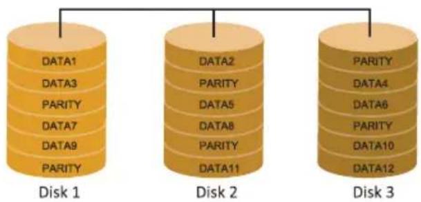
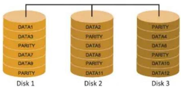
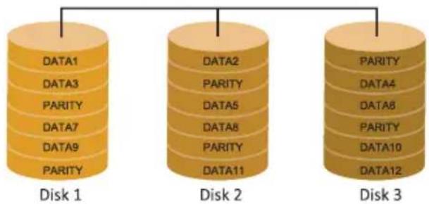
A RAID 5 array can withstand a single disk failure without losing data or access to data. Although RAID 5 can be achieved in software, a hardware controller is recommended. Often extra cache memory is used on these controllers to improve the write performance.
Features and Benefits
- Drives: Minimum 3.
- Uses: RAID 5 is recommended for transaction processing and general purpose service.
- Benefits: An ideal combination of good performance, good fault tolerance, and high capacity and storage efficiency.
- Drawbacks: Individual block data transfer rate same as a single disk. Write performance can be CPU intensive.
- Fault Tolerance: Yes.
Note
» For more details settings about Intel® Rapid Storage Technology (Intel® RST), please visit http://www.intel.com/p/en_US/support/highlights/chpsts/imsm
APPENDIX: Specifications in Other Languages
Arabic
| LGA1851 Intel® Core 1 www.bio31406 | ### | |
| Intel® Z890 | ### | |
| / 9066+(OC)/ 8933(OC)/ 8800(OC)/ 8600(OC)/ 8400(OC)/ 8266(OC)/ 8200(OC) 8000(OC)/ 7800(OC)/ 7600(OC)/ 7400(OC)/ 7200(OC)/ 7000(OC)/ 6800(OC) 6600(OC)/ 6400(OC)/ 6200(OC)/ 6000(OC)/ 5800(OC)/ 5600.### ### ### ### ### ### ### ### ### ### ### ### ### ### ### ### ### ### ### ### ### ### ### ### ### ### ### ### ### ### ### ### ### ### ### ### ### ### ### ### ### ### ### ### ### ### ### ### ### ### ### ### ### ### ### ### ### ### ### ### ### ### ### ### ### ### ### ### ### ### ### ### ### ### ### ### ### ### ### ### ### ### ### ### ### ### ### ### ### ### ### ### ### ### ### ### ### ### ### ### ### ###### ###### ###### ###### ###### ###### ###### ###### ###### ###### ###### ###### ###### ###### ###### ###### ###### ###### ###### ###### ###### ###### ###### ###### ###### ###### ###### ###### ###### ###### ###### ###### ###### ###### ###### ###### ###### ###### ###### ###### ###### ###### ###### ###### ###### ###### ###### ###### ###### ###### ####### ###### ###### ###### ###### ###### ###### ###### ###### ###### ###### ###### ###### ###### ###### ###### ###### ###### ###### ###### ###### ###### ###### ###### ###### ###### ###### ###### ###### ###### ###### ###### ###### ###### ###### ###### ###### ###### ###### ###### ###### ###### ###### ###### ###### ###### ###### ###### ###### ###### ##### ###### ###### ###### ###### ###### ###### ###### ###### ###### ###### ###### ###### ###### ###### ###### ###### ###### ###### ###### ###### ###### ###### ###### ###### ###### ###### ###### ###### ###### ###### ###### ###### ###### ###### ###### ###### ###### ###### ###### ###### ###### ###### ###### ###### ###### ###### ###### ###### ###### ###### . Intel® Extreme Memory Profile (XASR) www.bio31406 | ||
| (6Gb/s) SATADMA21 Intel Core Ultra Processors : (M2M_CPU)N@ # × 1 M.2 Type 2280SSD NVMe SSD - (128Gb/s) PCIe 5.0 x4 : (M2M_CPU)N@ # × 1 M.2 Type 2280SSD NVMe SSD - (64Gb/s) PCIe 4.0 x4 : (M2M_CPU)N@ # × 1 M.2 Type 2280SSD NVMe SSD - (64Gb/s) PCIe 4.0 x4 : (M2M_CPU)N@ # × 1 M.2 Type 2280SSD NVMe SSD - (64Gb/s) PCIe 4.0 x4 : (M2M_CPU)N@ # × 1 N.2 Type 2280SSD NVMe SSD - (64Gb/s) PCIe 4.0 x4 : (M2M_CPU)N@ # × 1 M.2 Type 2280SSD NVMe SSD - (64Gb/s) PCIe 4.0 x4 : (M2M_CPU)N@ # × 1 M.2 Type 2280SSD NVMe SSD - (64Gb/s) PCIe 4.0 x4 : (M2M_CPU)N@ # × 1 M.2 Type 2280SSD NVMe SSD - (64Gb/s) PCIe 4.0 x4 : (M2M_CPU)N@ # × 1 M.2 Type 2280SSD NVMe SSD - (64Gb/s) PCIe 4.0 x4 : (M2M_CPU)N# @ # × 1 M.2 Type 2280SSD NVMe SSD - (64Gb/s) PCIe 4.0 x4 : (6Gb/s) SATA III ## ## ## ## ## ## ## ## ## ## ## ## ## ## ## ## ## ## ## ## ## ## ## ## ## ## ## ## ## ## ## ## ## ## ## ## ## ## ## ## ## ## ## ## ## ## ## ## ## ## ## ## ## ## ## ## ## ## ## ## ## ## ## ## ## ## ## ## ## ## ## ## ## ## ## ## ## ## ## ## ## ## ## ## ## ## ## ## ## ## ## ## ## ## ## ## ## ## ## ## # | ||
| RAID DATA5, 10 RAID DATA5, 10 RAID DATA5, 10 RAID DATA5, 10 RAID DATA5, 10 RAID DATA5, 10 RAID DATA5, 10 RAID DATA5, 10 RAID DATA5, 10 RAID DATA5, 10 RAID DATA5, 10 RAID DATA5, 10 RAID DATA5, 10 RAID DATA5 | RAID DATA5, 10 RAID DATA5, 10 RAID DATA5, 10 RAID DATA5, 10 RAID DATA5, 10 RAID DATA5, 10 RAID DATA5, 10 RAID DATA5, 10 RAID DATA5, 10 RAID DATA5, 10 RAID DATA5, 10 RAID DATA5, 10 RAID Data5, 10 RAID DATA5, 10 RAID DATA5, 10 RAID DATA5, 10 RAID DATA5, 10 RAID DATA5, 10 RAID DATA5, 10 RAID DATA5, 10 RAID DATA5, 10 RAID DATA5, 10 RAID DATA5, 10 RAID DATA5, 10 RAID DATA5, 2500/100/10 Realtek® RTL8125D Realtek® RTL8125D Realtek® ALC1220 ### ### ### ### ### ### ### ### ### ### ### ### ### ### ### ### ### ### ### ### ### ### ### ### ### ### ### ### ### ### ### ### ### ### ### ### ### ### ### ### ### ### ### ### ### ### ### ### ### ### ### ### ### ### ### ### ### ### ### ### ### ### ### ### ### ### ### ### ### ### ### ### ### ### ### ### ### ### ### ### ### ### ### ### ### ### ### ### ### ### ### ### ### ### ### ### ### ### ### ## | |
| USB USB 3.2 (Gen2421 USB 3.2 (Gen2421 USB 3.2 (Gen2421 USB 3.2 (Gen2421 USB 3.2 (Gen2421 USB 3.2 (Gen2421 USB 3.2 (Gen2421 USB 3.2 (Gen2421 USB 3.2 (Gen2421 USB 3.2 (Gen2421 USB 2.40) USB 2.40) USB 2.40) USB 2.40) USB 2.40) USB 2.40) USB 2.40) USB 2.40) USB 2.40) USB 2.40) USB 2.40) USB 2.40) USB 2.40) USB 2.40) USB 2.40) USB 3.2 (Gen2421 USB 3.2 (Gen2421 USB 3.2 (Gen2421 USB 3.2 (Gen2421 USB 3.2 (Gen2421 USB 3.2 (Gen2421 USB 3.2 (Gen2421 USB 3.2 (Gen2421 USB 3.2 (Gen2421) USB 3.2 (Gen2421 USB 3.2 (Gen2421 USB 3.2 (Gen2421 USB 3.2 (Gen2421 USB 3.2 (Gen2421 USB 3.2 (Gen2421 USB 3.2 (Gen2421 USB 3.2 (Gen2421) USB 3.2 (Gen2420) USB 3.2 (Gen2420) USB 3.2 (Gen2420) USB 3.2 (Gen2420) USB 3.2 (Gen2420) USB 3.2 (Gen2420) USB 3.2 (Gen2420) USB 3.2 (Gen2420) USB 3.2 (Gen2420) USB 2.40) USB 2.40) USB 2.40) USB 2.40) USB 2.40) USB 2.40) USB 2.40) USB 2.40) USB 2.40) USB 2.40) USB 2.40) USB 2.40) USB 2.40) USB 2.40)(GB 2.40) USB 2.40) USB 2.40) USB 2.40) USB 2.40) USB 2.40) USB 2.40) USB 2.40) USB 2.40) USB 2.40) USB 2.40) USB 2.40) USB 2.40) USB 2.40) USB 1.40) USB 1.40) USB 1.40) USB 1.40) USB 1.40) USB 1.40) USB 1.40) USB 1.40) USB 1.40) USB 1.40) USB 1.40) USB 1.40) USB 1.40) USB 1.40) USB 1.30) USB 1.30) USB 1.30) USB 1.30) USB 1.30) USB 1.30) USB 1.30) USB 1.30) USB 1.30) USB 1.30) USB 1.30) USB 1.30) USB 1.30) USB 1.30) USB 1.30)(GB 2.40) USB 2.40) USB 2.40) USB 2.40) USB 2.40) USB 2.40) USB 2.40) USB 2.40) USB 2.40) USB 2.40) USB 2.40) USB 2.40) USB 2.40) USB 2.40)(GB 3.2 (Gen2421 USB 3.2 (Gen2421 USB 3.2 (Gen2421 USB 3.2 (Gen2421 USB 3.2 (Gen2421 USB 3.2 (Gen2421 USB 3.2 (Gen2421 USB 3.2 (Gen2421) USB 3.2 (Gen2421) USB 3.2 (Gen2421) USB 3.2 (Gen2421) USB 3.2 (Gen2421) USB 3.2 (Gen2421) USB 3.2 (Gen2421) USB 3.2 (Gen2421) USB 3.2 (Gen2421) USB 3.A.1 (GB 2.40) USB 3.A.1 (GB 2.40) USB 3.A.1 (GB 2.40) USB 3.A.1 (GB 2.40) USB 3.A.1 (GB 2.40) USB 3.A.1 (GB 2.40) USB 3.A.1 (GB 2.40) USB 3.A.1 (GB 2.40) | ||
| د ي نحّذ | ||
| Intel Core Ultra Processorsالر.2016.5.0×26الر.2016.5.0×26الر.2016.4e 5.0×26الر.2016.4e 5.0×26الر.2016.4e 5.0×26الر.2016.4e 5.0×26الر.2016.4e 5.0×26الر.2016.4e 5.0×26الر.2016. | ||
| يَأْفَمِنْمُدُ (RDM)2.1(1)DP (DP241)USB 2.1(1).USB 3.2 (Gen29)الر.2016.5.0×26الر.2016.5.0×26الر.2016.5.0×26الر.2016.5.0×26الر.2016.5.0×26الر.2016.5.0×26الر.2016.5.0×26الر.2016.5.0×26الدَرَجَاب وَمَلَ لَفَطَ تَكَتَتَ | يَأْفَمِنْمُدُ (RDM)2.1(1)DP (DP241)USB 2.1(1).USB 3.2 (Gen29)الر.2016.5.0×26الر.2016.5.0×26الر.2016.5.0×26الر.2017.5.0×26الر.2017.5.0×26الر.2017.5.0×26الر.2017.5.0×26الر.2017.5.0×26الر.2017.5.0×26الر.2017.5.0×26الر.2017. | |
| (6Gb/s)-SA7A-IIIIntel® GEN2 CNBIU60000000000000000000000000000000000000000000000000000000000000000000000000000000000000000000000000000 | (6Gb/s)-SA7A-IIIIntel® GEN2 CNBIU600000000000000000000000000000000000000000000000000000000000000000000000000000000 | |
| (6Gb/s)-SA7A-IIIIntel® GEN2 CNBIU600000000000000000000000000000000000000000000000000000000000000000000000000000 | (6Gb/s)-SA7A-IIIIntel® GEN2 CNBIU600018600000000000000000000000000000000000000000000000000000000000000000000000000000000000000000000000000 | |
| (6Gb/s)-SA7A-IIIIntel® GEN2 CNB1U60000000000000000000000000000000000000000000000000000000000000000000000000000000000000 | (6Gb/s)-SA7A-IIIIntel® GEN1 U600000000000000000000000000000000000000000000000000000000000000000000000000000000000000 | |
| (6Gb/s)-SA7A-31186(1)13186(1)10الر.2016.5.0×26الر.2016.5.0×26الر.2016.5.0×26الر.2016.5.0×26الر.2016.5.0×26الر.2016.5.0×26الر.2016.5.0×26ال德.2016.5.0×26ال德.2016.5.0×26ال德.2016.5.0×26ال德.2016.5.0×26ال德.2016.5.0×26ال德.2016.5.0×26ال德.2016.5.0×26ال德. | ||
German
natural_image
Technical diagram of a computer motherboard showing a highlighted component and its exploded view (no text or labels)Примечание
natural_image
Technical illustration of a mechanical component with mounting flanges and a central housing (no text or symbols)natural_image
3D diagram of a mechanical assembly with a blue arrow indicating rotation, no text or symbols presentnatural_image
3D diagram of a mechanical component with a blue arrow indicating rotation or movement (no text or symbols)Примечание
| Pin Assignment |
| 1 Ground |
| 2 +12V |
| 3 FAN RPM rate sense |
| 4AI Fan Control |
| Pin Assignment |
| 1 Ground |
| 2 +12V |
| 3 FAN RPM rate sense |
| 4Al Fan Control |
Примечание
natural_image
Technical line drawing of a RAM module with mounting bracket and clamping mechanism (no text or symbols)natural_image
Technical line drawing of a mechanical component with directional arrows indicating motion (no text or symbols)Примечание
natural_image
Technical line drawing of a mechanical assembly with two circular components and a 30-degree rotation indicator (no text or symbols)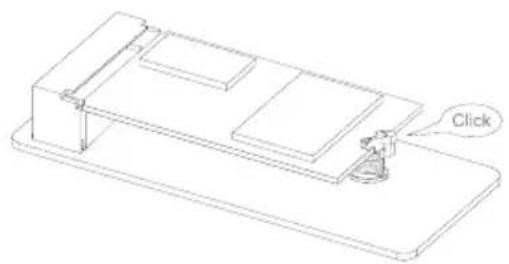
natural_image
Technical line drawing of a mechanical assembly with a labeled 'Click' button (no other text or symbols)natural_image
Technical line drawing of a mechanical assembly with a gear mechanism and a circular component inset (no text or symbols)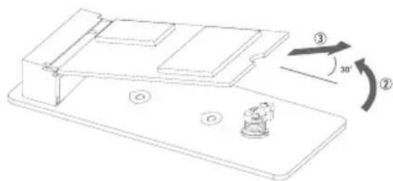
natural_image
Technical line drawing of a mechanical assembly with labeled components and angular indicators (no text or symbols)natural_image
Technical line drawing of a mechanical component with a rotating knob and mounting holes (no text or symbols)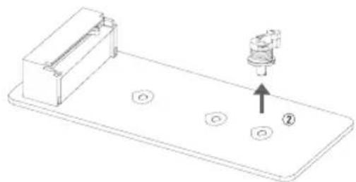
natural_image
Technical line drawing of a mechanical component with mounting holes and a labeled component (no text or symbols present)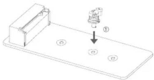
natural_image
Technical line drawing of a mechanical assembly with a component and mounting holes (no text or symbols)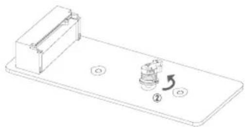
natural_image
Technical line drawing of a mechanical component with two circular holes and a rotating button (no text or symbols)PCIe Release Device
Установка карты PCI Express
flowchart
graph TD
    A["① ON"] --> B["②"]
    B --> C["③ OFF"]
| Pin Assignment |
| 1 +12V |
| 2 +12V |
| 3 +12V |
| 4+12V |
| 5 Ground |
| 6 Ground |
| 7Ground |
| 8Ground |
Примечание
| Pin | Assignment Fun | nction Pin | Assignment Function | |
| 1 HDD | LED(+) | HDD | 2 Power LED (+) | Power LED |
| 3 HDD | LED(-) 4Pow | EDED (-) | ||
| 5 Ground | Reset | 6 Power Button | Power-On Button | |
| 7Reset Control 8G | Button | |||
| 9NC NC 10 NA NA | ||||
| Pin | Assignment |
| 1 | Ground |
| 2 | TX+ |
| 3 | TX- |
| 4 | Ground |
| 5 | RX- |
| 6 | RX+ |
| 7 | Ground |
| Pin Assignment |
| 1 Carrier detect |
| 2 Received data |
| 3 Transmitted data |
| 4Data terminal ready |
| 5 Signal ground |
| 6 Data set ready |
| 7Request to send |
| 8Clear to send |
| 9Ring indicator |
| 10 Key |
SW_PWR(Питание):
VALKYRIE AURORA Utility
Нажмите «Yes»
RAID 5
parity across disks
flowchart
graph TD
    subgraph Disk 1
        A1["DATA1"] --> B1["PARITY"]
        A3["DATA3"] --> B1
        A7["DATA7"] --> B1
        A9["DATA9"] --> B1
        A1 --> B2["PARITY"]
        B2 --> C1["DATA5"]
        B2 --> C2["PARITY"]
        B2 --> C3["DATA8"]
        B2 --> C4["PARITY"]
        B2 --> C5["DATA11"]
    end
    subgraph Disk 2
        D2["DATA2"] --> E2["PARITY"]
        D2 --> F2["DATA6"]
        D2 --> G2["PARITY"]
        D2 --> H2["DATA10"]
        D2 --> I2["PARITY"]
        D2 --> J2["DATA12"]
    end
    subgraph Disk 3
        K2["PARITY"] --> L2["DATA4"]
        K2 --> M2["DATA6"]
        K2 --> N2["PARITY"]
        K2 --> O2["DATA10"]
        K2 --> P2["DATA12"]
natural_image
Diagram of a computer motherboard showing a slot and internal components, with an arrow indicating a specific area (no text or symbols present)주의
4 CPU 보호 덧개를 덧습니다.
natural_image
Technical illustration of a mechanical component with mounting holes and a curved arrow indicating rotation (no text or symbols)5 플라스틱 보호덮개를 제거합니다.
natural_image
3D mechanical assembly diagram showing a component mounted on a base plate with a blue arrow indicating rotation (no text or symbols)natural_image
3D technical diagram of a mechanical component with mounting flanges and a blue rotation arrow (no text or symbols)주의
| 핀 | 배열 |
| 1 Ground | |
| 2 + 12V | |
| 3 FAN RPM rate sense | |
| 4 A | Fan Control |
SYS_FAN1/ SYS_FAN2/ SYS_FAN3/ SYS_FAN4: 시스템 팬 헤더
| 핀 | 배열 |
| 1 Ground | |
| 2 + 12V | |
| 3 FAN RPM rate sense | |
| 4 A | Fan Control |
주의
natural_image
Technical line drawing of a RAM module with a blue circular component and directional arrows indicating rotation (no text or symbols)natural_image
Technical line drawing of a mechanical component with directional arrows indicating motion (no text or symbols)주의
| DIMM소켓 위치 DDR5 모듈 총 메모리 크기 | |
| DDR5_A1 8GB/16GB/24GB/32GB/48GB | 최대 192GB. |
| DDR5_A2 8GB/16GB/24GB/32GB/48GB | |
| DDR5_B1 8GB/16GB/24GB/32GB/48GB | |
| DDR5_B2 8GB/16GB/24GB/32GB/48GB |
듀얼 채널 메모리 설치
natural_image
Technical line drawing of a mechanical assembly with two circular components and directional arrows indicating rotation (no text or symbols)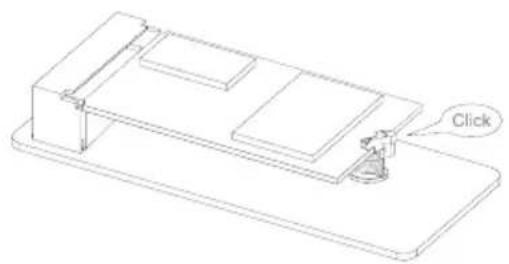
natural_image
Isometric line drawing of a mechanical component with a labeled 'Click' button (no other text or symbols)M.2 SSD 카드 제거
natural_image
Technical line drawing of a mechanical assembly with a gear mechanism and a circular component inset (no text or symbols)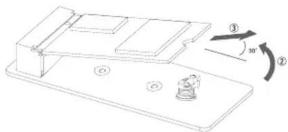
natural_image
Technical line drawing of a mechanical component with mounting holes and a rotating knob (no text or symbols)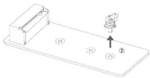
natural_image
Technical line drawing of a mechanical component with mounting holes and a labeled assembly (no text or symbols)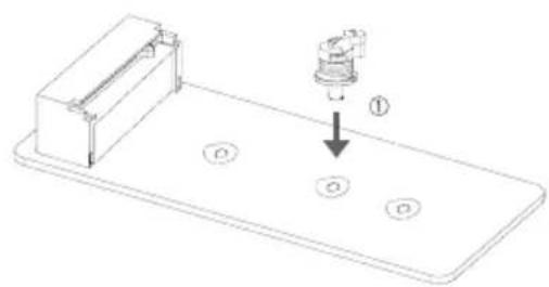
natural_image
Technical line drawing of a mechanical assembly with a component and three circular holes (no text or symbols)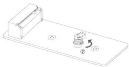
natural_image
Technical line drawing of a mechanical component with mounting holes and a rotating shaft (no text or symbols)PCIe Release Device
PCIe 릴리스 장치
flowchart
graph TD
    A["① ON"] --> B["②"]
    B --> C["③ OFF"]
PCI Express 카드 제거
2.6 헤더 & 커넥터
ATX: ATX 전원 커넥터
| 핀 | 배열 |
| 1 Ground | |
| 2 TX+ | |
| 3 TX- | |
| 4 Ground | |
| 5 RX- | |
| 6 RX+ | |
| 7Ground | |
| HD Audio | |
| 핀 | 배열 |
| 1 Mic Left in | |
| 2 Ground | |
| 3 Mic Right in | |
| 4 GPIO | |
| 5 Right line in | |
| 6 Jack Sense | |
| 7Front Sense | |
| 8 Key | |
| 9 Left line in | |
| 10 Jack Sense | |
주의
5V\_LED1/ 5V\_LED2/ 5V\_LED3/ 5V\_LED4: Addressable RGB LED 헤더
인디케이터
SW\_PWR (전원):
3.4 소프트웨어
소프트웨어의 설치
VALKYRIE AURORA Utility
"Yes" 를 누릅니다.
natural_image
Diagram of a computer motherboard showing a slot and internal components, with an arrow indicating a process or assembly (no text or symbols present)注意
natural_image
Technical illustration of a mechanical component with mounting flanges and internal components (no text or symbols)步驟 5: 取下塑膠保護殼。
natural_image
Mechanical assembly diagram showing a component being rotated with a blue arrow (no text or symbols present)步驟 6: 將 ILM 拉桿完全閉合。
natural_image
Technical diagram of a mechanical component with mounting flanges and a blue rotation arrow (no text or symbols)注意
natural_image
Technical line drawing of a RAM module with a clamping mechanism and rotation indicator (no text or symbols)natural_image
Technical line drawing of a mechanical component with directional arrows indicating motion (no text or symbols)注意
| 雙通道狀態 DDR5_A1 DDR5_A2 DDR5_B1 DDR5_B2 | |
| Enabled X O X O | |
| Enabled O O O O |
natural_image
Technical line drawing of a mechanical assembly with two circular components and an arrow indicating rotation (no text or symbols)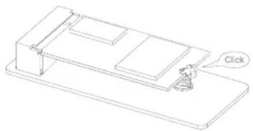
natural_image
Isometric line drawing of a mechanical component with a labeled 'Click' button (no other text or symbols)移除 M.2 SSD 卡
natural_image
Technical line drawing of a mechanical assembly with a gear mechanism and a circular component inset (no text or symbols)
natural_image
Technical line drawing of a mechanical assembly with numbered components and angular annotations (no readable text or symbols)“M.2 旋轉自動扣具” 更換孔位:移除、安裝
natural_image
Technical line drawing of a mechanical component with mounting holes and a rotating knob (no text or symbols)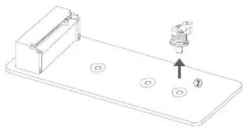
natural_image
Technical line drawing of a mechanical component with mounting holes and a labeled component (no text or symbols present)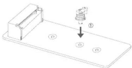
natural_image
Technical line drawing of a mechanical assembly with a component and circular base (no text or symbols)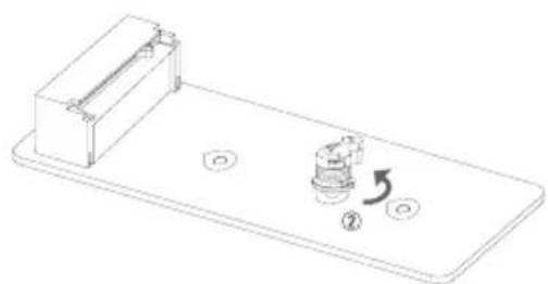
natural_image
Technical line drawing of a mechanical component with mounting holes and a rotating knob (no text or symbols)PCIe Release Device
安装 PCI Express 卡
flowchart
graph TD
    A["① ON"] --> B["②"]
    B --> C["③ OFF"]
移除 PCI Express 卡
2.6 接頭和插槽
ATX: ATX電源插槽
指示器
LED燈
![BIOSTAR BIO-FLASHER PPS File +PSL Total PTS = 2 Information Project Name: 2016/74 B338 Date: 07/25/2021 File: B338 B338 Flash mode,reset, cycles! (1/2) Flashing [DIRECT13.BST] mov to update (1) now Start B338/74.BST B338/74.BST B338/74.BST B338/74.BST B338/74.BST B338/74.BST B338/74.BST 100% ESC: Quit TAB: Change B: Select](/content/2026/05/910318/images/a87ecd3bf00b6c4971db55a585fcbff23069f681cc653b320f355a50b8376063.jpg)
BIOS備份
3.4 軟體
安裝軟體
VALKYRIE AURORA Utility
- 溫度(Temperature):顯示當前CPU和系統溫度。
- CPU FAN/ CPU OPT RPM & SYSTEM1/2/3/4 RPM :
按 "Yes"
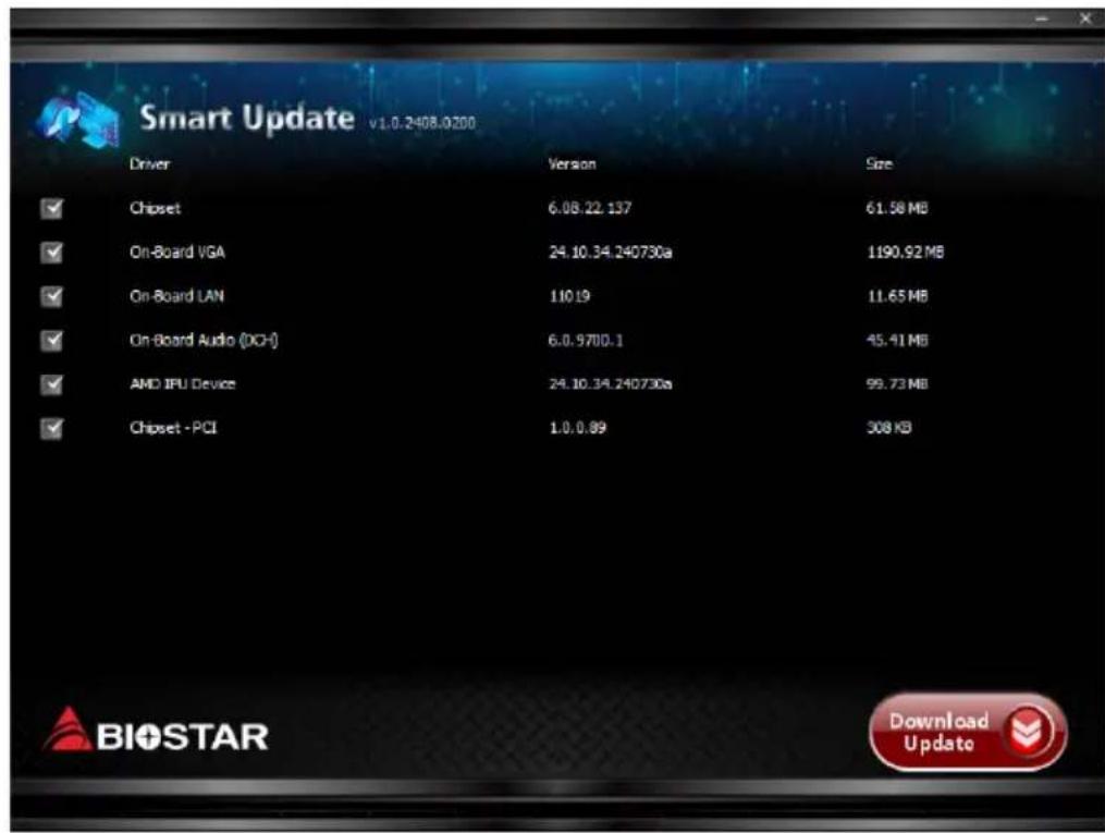
按右下角 “Download Update”
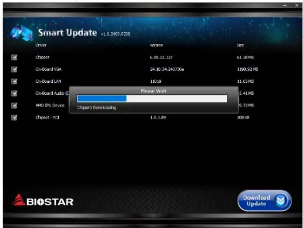
等待下載過程完成。
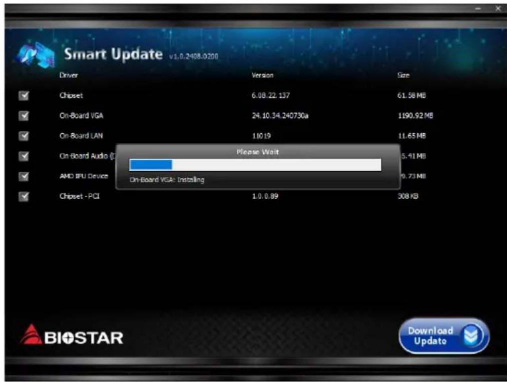
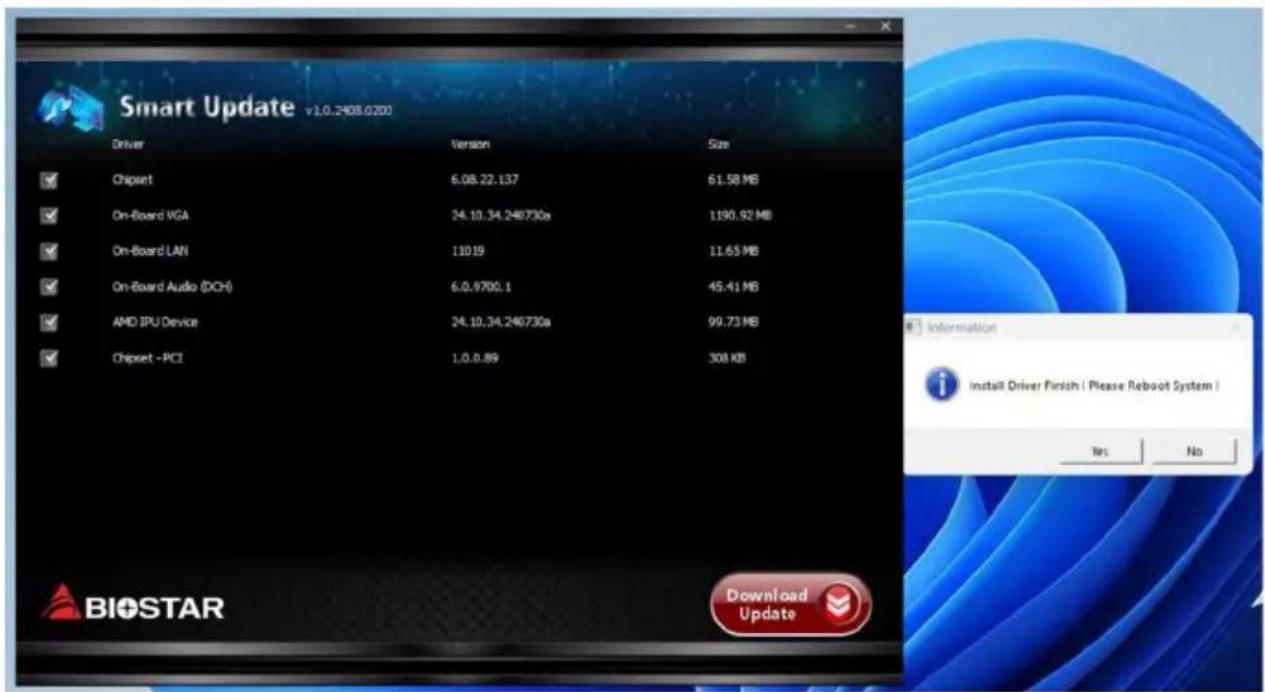
下載並安裝完成後,請重新啟動系統。
4.2 RAID 功能
RAID 定義
flowchart
graph TD
    A["RAID 0 striping"] --> B["Block 1"]
    A --> C["Block 2"]
    B --> D["Disk 1"]
    C --> E["Disk 2"]
    D --> F["Block 5"]
    E --> G["Block 4"]
RAID 5
parity across disks
flowchart
graph TD
    subgraph Disk 1
        A1["DATA1"] --> B1["PARITY"]
        A3["DATA3"] --> B1
        A7["DATA7"] --> B1
        A9["DATA9"] --> B1
        A1 --> B2["PARITY"]
        B2 --> C1["DATA5"]
        B2 --> C2["PARITY"]
        B2 --> C3["DATA8"]
        B2 --> C4["PARITY"]
        B2 --> C5["DATA11"]
    end
    subgraph Disk 2
        D1["DATA2"] --> E1["PARITY"]
        D2["DATA4"] --> E1
        D3["DATA8"] --> E1
        D3 --> E2["PARITY"]
        D3 --> E3["DATA10"]
        D3 --> E4["DATA12"]
    end
    subgraph Disk 3
        F1["PARITY"] --> G1["DATA4"]
        F2["DATA8"] --> G1
        F3["PARITY"] --> G2["DATA10"]
        F3 --> G3["DATA12"]
- FCC Information and Copyright
- Avoidance of electrostatic operation rules
- Warning
- Table Of Contents
- Chapter 1: Introduction......4
- Chapter 2: Hardware installation....9
- Chapter 3: UEFI BIOS & Software....27
- Chapter 4: Useful help.... 44
- APPENDIX: Specifications in Other Languages 49
- Chapter 1: Introduction
- Before You Start
- Specifications
- Rear Panel Connectors
- Note
- Chapter 2: Hardware installation
- Install Central Processing Unit (CPU)
- Install a Heatsink
- Connect Cooling Fans
- Install System Memory
- DDR5 Modules
- Dual Channel Memory Installation
- Expansion Slots
- PCIEX16\_1: PCI-Express Gen5 x16 Slots (x16 or x8 mode)
- PCIEX16\_2: PCI-Express Gen5 x16 Slots (x8 or x4 mode)
- PCIEX16\_3: PCI-Express Gen5 x16 Slots (x4 mode)
- M2M\_CPU\_1: M.2 (M Key) Socket
- M2M\_CPU\_2: M.2 (M Key) Socket
- M2M\_SB1: M.2 (M Key) Socket
- M2M\_SB2: M.2 (M Key) Socket
- M2M\_SB3: M.2 (M Key) Socket
- M2M\_SB4: M.2 (M Key) Socket
- M2E\_WIFI: M.2 (E Key) Socket (M.2 (E Key) Wi-Fi card is not provided)
- Install an Expansion Card
- Installing M.2 Rotary Auto Anchor
- PCIe Release Device
- Installing an PCI Express card
- Remove the PCI Express card
- Headers & Connectors
- ATX: ATX Power Source Connector
- ATX\_12V\_2X4\_1/ ATX\_12V\_2X4\_2: ATX Power Source Connector
- ATX Power Connection
- F\_PANEL: Front Panel Header
- TPM\_SPI: Trusted Platform Module Header
- SATA\_1/ SATA\_2/ SATA\_3/ SATA\_4: Serial ATA 6.0 Gb/s Connectors
- F\_USB32\_C-20G: Header for USB 3.2 (Gen2x2) Ports at Front Panel
- F\_USB32\_A-10G: Header for USB 3.2 (Gen2) Ports at Front Panel
- F\_USB20\_1/ F\_USB20\_2: Header for USB 2.0 Ports at Front Panel
- THUNDERBOLT: Thunderbolt Header
- F\_AUDIO: Front Panel Audio Header
- COM: Serial Port Header
- 12V\_LED: RGB LED Header
- 5V\_LED1/ 5V\_LED2/ 5V\_LED3/ 5V\_LED4: Addressable RGB LED Header
- Buttons, Indicators & LEDs
- SW\_PWR:
- SW\_RST:
- CLR\_CMOS:
- BIOS POST Code Indicator:
- LEDs
- Chapter 3: UEFI BIOS & Software
- UEFI BIOS Setup
- BIOS Update
- Motherboard BIOS Update
- BIOSTAR BIO-Flasher
- Updating BIOS with BIOSTAR BIO-Flasher
- BIOS Update Utility (through the Internet)
- BIOS Update Utility (through a BIOS file)
- Backup BIOS
- Software
- Installing Software
- Launching Software
- BIOScreen Utility
- Vivid LED DJ
- VALKYRIE AURORA Utility
- System Information
- SmartEAR
- Requirements:
- Installation Guide:
- GT Touch
- A.I Fan
- H/W Monitor
- oc/ov
- About
- Chapter 4: Useful help
- Auto Installer
- RAID Functions
- Features and Benefits
- APPENDIX: Specifications in Other Languages
- Примечание
- Установка карты PCI Express
- 주의
- 듀얼 채널 메모리 설치
- M.2 SSD 카드 제거
- PCIe 릴리스 장치
- PCI Express 카드 제거
- 헤더 & 커넥터
- ATX: ATX 전원 커넥터
- 5V\_LED1/ 5V\_LED2/ 5V\_LED3/ 5V\_LED4: Addressable RGB LED 헤더
- 인디케이터
- SW\_PWR (전원):
- 소프트웨어
- 소프트웨어의 설치
- 注意
- 安装 PCI Express 卡
- 移除 PCI Express 卡
- 接頭和插槽
- ATX: ATX電源插槽
- LED燈
- BIOS備份
- 軟體
- 安裝軟體
- RAID 功能
- RAID 定義
Brand : BIOSTAR
Model : Z890 VALKYRIE
Category : Motherboard