Sprite Lite (2012) - Caravan Swift - Free user manual and instructions
Find the device manual for free Sprite Lite (2012) Swift in PDF.


| Product Type | Caravan |
| Brand | Swift |
| Model | Sprite Lite (2012) |
| Overall Length | 6.45 m (21 ft 2 in) |
| Overall Width | 2.23 m (7 ft 4 in) |
| Overall Height (incl. aerial) | 2.61 m (8 ft 7 in) |
| Maximum Internal Headroom | 1.95 m (6 ft 5 in) |
| Mass in Running Order (MRO) | 916 kg (8.0 cwt) |
| Maximum Technically Permissible Laden Mass (MTPLM) | 1100 kg (21.7 cwt) |
| Total User Payload | 121 kg (2.4 cwt) |
| Static Load on Coupling Head | 100 kg |
| Tyre Size | 175 R14C 99R |
| Tyre Pressure (lower limit MTPLM) | 45 psi / 3.1 bar |
| Thermal Insulation Grade | Two |
| Bed Size (Front Double) | 208 cm x 180 cm (6 ft 10 in x 5 ft 11 in) |
| Power Supply | 230V mains (RCD protected) and 12V battery system |
| Power System | EC155 Power Control System with 150W converter/charger |
| Number of Axles | 1 |
| Lighting | Halogen ceiling lights, fluorescent strip lights, and road lighting |
| Safety Features | RCD, MCBs, over-discharge protection, battery save circuit |
| Maintenance | Bulb replacement accessible via lens screws; battery inspection and topping up |
| Spare Parts | Contact Swift dealer or Sargent Electrical Services for parts |
Frequently Asked Questions - Sprite Lite (2012) Swift
User questions about Sprite Lite (2012) Swift
0 question about this device. Answer the ones you know or ask your own.
Ask a new question about this device
Download the instructions for your Caravan in PDF format for free! Find your manual Sprite Lite (2012) - Swift and take your electronic device back in hand. On this page are published all the documents necessary for the use of your device. Sprite Lite (2012) by Swift.
USER MANUAL Sprite Lite (2012) Swift
Dunswell Road, Cottingham, East Yorkshire, HU16 4JX.
Tel: 01482 875740 Fax: 01482 840082
email: enquiry@swiftgroup.co.uk
website: www.swiftgroup.co.uk
A MEMBER OF THE SWIFT GROUP
1098243 issued October 2011
Contents
Specification 3
Wiring Diagrams - Road Lighting 4
Wiring Diagrams - Roof Circuits 5
Wiring Diagrams - Floor Circuits 6
Wiring Diagrams - 230v Circuits .... 7
Wiring Diagrams - Power Circuits 8
Wiring Diagrams - 13 pin Socket .... 9
Wiring Diagrams - Cable Colours 10
Bulb Chart 11
Bulb Replacement 12
EC155 Power Control Panel 13
Specification
Wiring Diagrams
| Sprite Lite Sprite Lite 2 Sprite Lite 4 Sprite Lite 5 | |||
| Betts 2 4 5 | |||
| Axles 1 1 1 | |||
| Internal Longlin (bcd box height) 4.34m 14/13" 4.74m/5.7" 4.74m/15.7" | |||
| Overall Width** 2.23m/7.4" 2.23m/7.4" 2.23m/7.4" | |||
| Overall Height Inc. IV Aerial** 2.61m 8.7" 2.61m/8.7" 2.61m/8.7" | |||
| Maximum Internal Headroom 1.95m/6.5" 1.95m/6.5" 1.95m/6.5" | |||
| Overall Length** 8.04m/19.10" 6.45m/21.2" 6.45m/21.2" | |||
| Awning A/A dimension 8.55m/26.1" 8.95m/29.4" | |||
| Mass in Running Order (inc. tolerance) | 916kg/8.0wt | 952kg/8.7cwt | 982kg/19.3cwt |
| Maximum Technical Permissible Laden Mass Lower Limit | 1096kg/20.4cwt | 1097kg/21.6cwt | 1137kg/22.4cwt |
| Maximum Technical Permissible Laden Mass Upper Limit | 1100kg/21.7cwt | 1150kg/22.6cwt | 1200kg/23.6cwt |
| Total user Payload | 121kg/2.4cwt | 145kg/2.9cwt | 155kg/3.1cwt |
| Personal Effects | 121g/2.4cwt 145kg/2.9cwt | 155kg/3.1cwt | |
| Options | 0kg/0cwt | 0kg/0cwt | 0kg/0cwt |
| Tyre Size | 175 R14C 99R | 175 R14C 99R | 175 R14C 99R |
| Tyre pressure at Lower limit MTPLM | 45 psi / 3.1 bar | 48 psi / 3.3 bar | 51 psi / 3.5 bar |
| Tyre pressure at Upper limit MTPLM | 48 psi / 3.3 bar | 51 psi / 3.5 bar | 54 psi / 3.7 bar |
| Static Load on Coupling Head | 100kg | 100kg | 100kg |
| Thermal Insulation Grade | TWO | TWO | TWO |
| Bed Sizes | |||
| Front Double | 208cm x 180cm/6'10" x 3'11" | 208cm x 134cm/6'10" x 4'5" | 208cm x 134cm/6'10" x 4'5" |
| or Front Nearside Single | 190cm x 72cm/6'3" x 2'4" | ||
| and Front Offside Single 180cm x 72cm/5'11" x 2'4" | |||
| Pear Double | 188cm x 137cm/6'2" x 4'6" | 194cm x 137/120cm/6'4" x 4'5" 3'11" | |
| Fear Bunk | |||
| Side Single (offside) | |||
| Side Single (nearside) | 194cm x 68cm/6'4" x 2'3" | ||
| Side Bunk (offside) | |||
| Side Bunk (nearside) | 180cm x 59cm/5'11" x 1'11" | ||
| Fear Fixed Lower Bunk | |||
| Fear Fixed Mid Bunk | |||
| Fear Fixed Upper Bunk | |||
| Side Fixed Lower Bunk | |||
| Side Fixed Mid Bunk | |||
| Side Fixed Upper Bunk | |||
Weights From the 2011 season the method of calculating the Mass in Running Order (MFC) and user payback figures has changed in order to bring it in line with European Vehicle Directives.
Allowances for essential equipment (e.g. gas cylinders previously allowed for in the other payload are now contained within the MPO. A provision for a ensure battery which used to be within the essential equipment payload has now been included within the personal effects payload allowance.
Although the method of calculation has changed, the overall effect is that the amount of supply available to the customer has remained the same. It is just calculated in a different manner
\* Estimated
Bed Sizes: Please note that the front double bed sizes quoted are for sealing configurations without chest of drawers. The front double bed width for a layout with a chest of drawer's fit was reduced by 0.4m(14") from that stated.
Awing sizes: Due to drawing owning designs and sizes the awning sizes other are approximate only. Specific awning sizes must be continued by your dealer or owning manufacturer over year to purchase.
** The dimensions given are approximate due to slight variations in suspension rule heights, loading conditions and 7/8 pressures.
Customers should verify the actual dimensions at their fouring canvas before committing to anything that could be impacted by these dimensions.
Please note: Any dealer if option is will choose the metal payment available to the user of the caravan. If you require action at payback it is possible to upgrade the MFM to the upper limit. Please clarify your Sare caravan dealer for more information.
Sprite Lite range - Road lighting
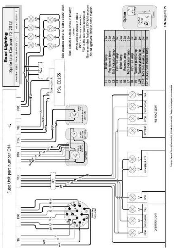
Sprite Lite range - Roof circuits Sprite Lite range - Floor circuits
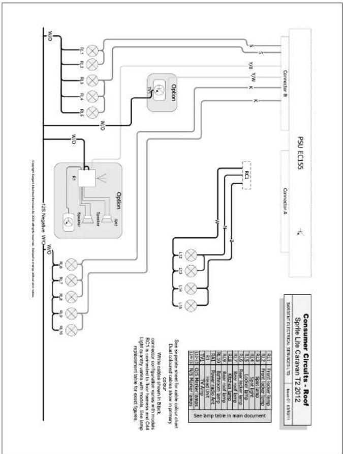
flowchart
graph TD
    A["PSU ECUSS"] --> B["CANDUARY A"]
    B --> C["Option"]
    C --> D["Option"]
    D --> E["125 Magnetic V/W"]
    E --> F["Output: 125 Magnetic V/W"]
    F --> G["Output: 125 Magnetic V/W"]
    G --> H["Output: 125 Magnetic V/W"]
    H --> I["Output: 125 Magnetic V/W"]
    I --> J["Output: 125 Magnetic V/W"]
    J --> K["Output: 125 Magnetic V/W"]
    K --> L["Output: 125 Magnetic V/W"]
    L --> M["Output: 125 Magnetic V/W"]
    M --> N["Output: 125 Magnetic V/W"]
    N --> O["Output: 125 Magnetic V/W"]
    O --> P["Output: 125 Magnetic V/W"]
    P --> Q["Output: 125 Magnetic V/W"]
    Q --> R["Output: 125 Magnetic V/W"]
    R --> S["Output: 125 Magnetic V/W"]
    S --> T["Output: 125 Magnetic V/W"]
    T --> U["Output: 125 Magnetic V/W"]
    U --> V["Output: 125 Magnetic V/W"]
    V --> W["Output: 125 Magnetic V/W"]
    W --> X["Output: 125 Magnetic V/W"]
    X --> Y["Output: 125 Magnetic V/W"]
    Y --> Z["Output: 125 Magnetic V/W"]
    Z --> AA["Output: 125 Magnetic V/W"]
    AA --> AB["Output: 125 Magnetic V/W"]
    AB --> AC["Output: 125 Magnetic V/W"]
    AC --> AD["Output: 125 Magnetic V/W"]
    AD --> AE["Output: 125 Magnetic V/W"]
    AE --> AF["Output: 125 Magnetic V/W"]
    AF --> AG["Output: 125 Magnetic V/W"]
    AG --> AH["Output: 125 Magnetic V/W"]
    AH --> AI["Output: 125 Magnetic V/W"]
    AI --> AJ["Output: 125 Magnetic V/W"]
    AJ --> AK["Output: 125 Magnetic V/W"]
    AK --> AL["Output: 125 Magnetic V/W"]
    AL --> AM["Output: 125 Magnetic V/W"]
    AM --> AN["Output: 125 Magnetic V/W"]
    AN --> AO["Output: 125 Magnetic V/W"]
    AO --> AP["Output: 125 Magnetic V/W"]
    AP --> AQ["Output: 125 Magnetic V/W"]
    AQ --> AR["Output: 125 Magnetic V/W"]
    AR --> AS["Output: 125 Magnetic V/W"]
    AS --> AT["Output: 125 Magnetic V/W"]
    AT --> AU["Output: 125 Magnetic V/W"]
    AU --> AV["Output: 125 Magnetic V/W"]
    AV --> AW["Output: 125 Magnetic V/W"]
    AW --> AX["Output: 125 Magnetic V/W"]
    AX --> AY["Output: 125 Magnetic V/W"]
    AY --> AZ["Output: 125 Magnetic V/W"]
    AZ --> BA["Output: 125 Magnetic V/W"]
    BA --> BB["Output: 125 Magnetic V/W"]
    BB --> BC["Output: 125 Magnetic V/W"]
    BC --> BD["Output: 125 Magnetic V/W"]
    BD --> BE["Output: 125 Magnetic V/W"]
    BE --> BF["Output: 125 Magnetic V/W"]
    BF --> BG["Output: 125 Magnetic V/W"]
    BG --> BH["Output: 125 Magnetic V/W"]
    BH --> BI["Output: 125 Magnetic V/W"]
    BI --> BJ["Output: 125 Magnetic V/W"]
    BJ --> BK["Output: 125 Magnetic V/W"]
    BK --> BL["Output: 125 Magnetic V/W"]
    BL --> BM["Output: 125 Magnetic V/W"]
    BM --> BN["Output: 125 Magnetic V/W"]
    BN --> BO["Output: 125 Magnetic V/W"]
    BO --> BP["Output: 125 Magnetic V/W"]
    BP --> BQ["Output: 125 Magnetic V/W"]
    BQ --> BR["Output: 125 Magnetic V/W"]
    BR --> BS["Output: 125 Magnetic V/W"]
    BS --> BT["Output: 125 Magnetic V/W"]
    BT --> BU["Output: 125 Magnetic V/W"]
    BU --> BV["Output: 125 Magnetic V/W"]
    BV --> BW["Output: 125 Magnetic V/W"]
    BW --> BX["Output: 125 Magnetic V/W"]
    BX --> BY["Output: 125 Magnetic V/W"]
    BY --> BZ["Output: 125 Magnetic V/W"]
Wiring DiagramsW
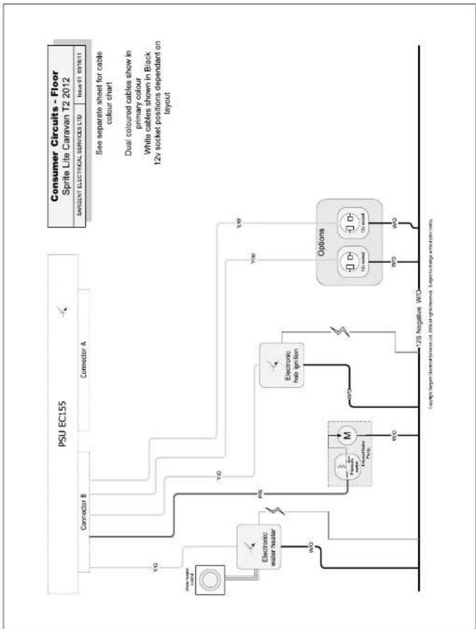
flowchart
graph TD
    A["PSU EC155"] --> B["Connector A"]
    A --> C["Connector B"]
    A --> D["Water heater control"]
    A --> E["Electronic water heater"]
    E --> F["PSB"]
    F --> G["Electronic hobe ignition"]
    G --> H["Options"]
    H --> I["12v socket"]
    H --> J["12v socket"]
    style A fill:#f9f,stroke:#333
    style B fill:#ccf,stroke:#333
    style C fill:#ccf,stroke:#333
    style D fill:#ccf,stroke:#333
    style E fill:#cfc,stroke:#333
    style F fill:#fcc,stroke:#333
    style G fill:#fcc,stroke:#333
    style H fill:#fcc,stroke:#333
    style I fill:#fff,stroke:#333
    style J fill:#fff,stroke:#333
Sprite Lite range - 230V circuits Sprite Lite range - Power circuits
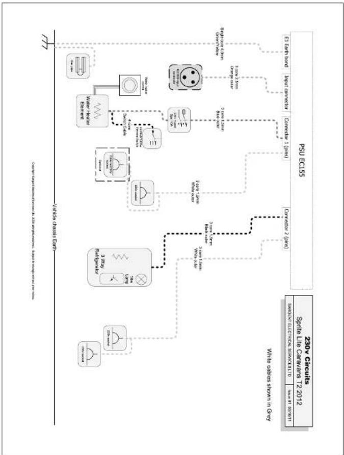
flowchart
graph TD
    A["230V Circuits\nSprite Line Carriages T2 2012"] --> B["PSU EC55"]
    B --> C["Switch Contact Control Service Card 1.0"]
    B --> D["Signal to EBITA"]
    B --> E["Input Control"]
    B --> F["Control 1 (P)"]
    B --> G["Control 2 (P)"]
    B --> H["Control 3 (P)"]
    B --> I["Control 4 (P)"]
    B --> J["Control 5 (P)"]
    B --> K["Control 6 (P)"]
    B --> L["Control 7 (P)"]
    B --> M["Control 8 (P)"]
    B --> N["Control 9 (P)"]
    B --> O["Control 10 (P)"]
    B --> P["Control 11 (P)"]
    B --> Q["Control 12 (P)"]
    B --> R["Control 13 (P)"]
    B --> S["Control 14 (P)"]
    B --> T["Control 15 (P)"]
    B --> U["Control 16 (P)"]
    B --> V["Control 17 (P)"]
    B --> W["Control 18 (P)"]
    B --> X["Control 19 (P)"]
    B --> Y["Control 20 (P)"]
    B --> Z["Control 21 (P)"]
    B --> AA["Control 22 (P)"]
    B --> AB["Control 23 (P)"]
    B --> AC["Control 24 (P)"]
    B --> AD["Control 25 (P)"]
    B --> AE["Control 26 (P)"]
    B --> AF["Control 27 (P)"]
    B --> AG["Control 28 (P)"]
    B --> AH["Control 29 (P)"]
    B --> AI["Control 30 (P)"]
    B --> AJ["Control 31 (P)"]
    B --> AK["Control 32 (P)"]
    B --> AL["Control 33 (P)"]
    B --> AM["Control 34 (P)"]
    B --> AN["Control 35 (P)"]
    B --> AO["Control 36 (P)"]
    B --> AP["Control 37 (P)"]
    B --> AQ["Control 38 (P)"]
    B --> AR["Control 39 (P)"]
    B --> AS["Control 40 (P)"]
    B --> AT["Control 41 (P)"]
    B --> AU["Control 42 (P)"]
    B --> AV["Control 43 (P)"]
    B --> AW["Control 44 (P)"]
    B --> AX["Control 45 (P)"]
    B --> AY["Control 46 (P)"]
    B --> AZ["Control 47 (P)"]
    B --> BA["Control 48 (P)"]
    B --> BB["Control 49 (P)"]
    B --> BC["Control 50 (P)"]
    B --> BD["Control 51 (P)"]
    B --> BE["Control 52 (P)"]
    B --> BF["Control 53 (P)"]
    B --> BG["Control 54 (P)"]
    B --> BH["Control 55 (P)"]
    B --> BI["Control 56 (P)"]
    B --> BJ["Control 57 (P)"]
    B --> BK["Control 58 (P)"]
    B --> BL["Control 59 (P)"]
    B --> BM["Control 60 (P)"]
    B --> BN["Control 61 (P)"]
    B --> BO["Control 62 (P)"]
    B --> BP["Control 63 (P)"]
    B --> BQ["Control 64 (P)"]
    B --> BR["Control 65 (P)"]
    B --> BS["Control 66 (P)"]
    B --> BT["Control 67 (P)"]
    B --> BU["Control 68 (P)"]
    B --> BV["Control 69 (P)"]
    B --> BW["Control 70 (P)"]
    B --> BX["Control 71 (P)"]
    B --> BY["Control 72 (P)"]
    B --> Z["Control 73 (P)"]
    B --> CA["Control 74 (P)"]
    B --> CB["Control 75 (P)"]
    B --> CC["Control 76 (P)"]
    B --> CD["Control 77 (P)"]
    B --> CE["Control 78 (P)"]
    B --> CF["Control 79 (P)"]
    B --> CG["Control 80 (P)"]
    B --> CH["Control 81 (P)"]
    B --> CI["Control 82 (P)"]
Wiring DiagramsW
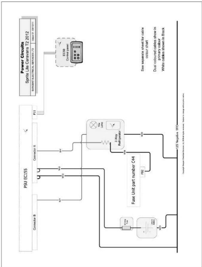
flowchart
graph TD
    A["PSU EC155"] --> B["Connector B"]
    A --> C["Connector A"]
    A --> D["P11"]
    E["Fuse Unit part number C44"] --> F["3 Way Refrigerator"]
    F --> G["EC50 Control panel"]
    H["Power Circuits Sprite Lite Caravans T2 2012"] --> I["BARGENT ELECTRICAL SERVICES LTD"]
    I --> J["123 Negative W/O"]
    K["123 Negative W/O"] --> L["ACB"]
    M["30 Amp Fuse"] --> N["ACB"]
    O["ACB"] --> P["ACB"]
    Q["ACB"] --> R["ACB"]
    S["ACB"] --> T["ACB"]
    U["ACB"] --> V["ACB"]
    W["ACB"] --> X["ACB"]
    Y["ACB"] --> Z["ACB"]
    AA["ACB"] --> AB["ACB"]
    AC["ACB"] --> AD["ACB"]
    AE["ACB"] --> AF["ACB"]
    AG["ACB"] --> AH["ACB"]
    AI["ACB"] --> AJ["ACB"]
    AK["ACB"] --> AL["ACB"]
    AM["ACB"] --> AN["ACB"]
    AO["ACB"] --> AP["ACB"]
    AQ["ACB"] --> AR["ACB"]
    AS["ACB"] --> AT["ACB"]
    AU["ACB"] --> AV["ACB"]
    AW["ACB"] --> AX["ACB"]
Sprite Lite range - 13 pin socket Sprite Lite range - Cable colours
- Tidal Plug Commander viewed from order entry on plan
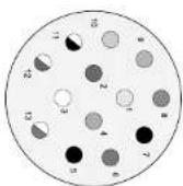
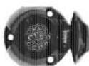
| 13 | vroomed | 2.5 | corn for 9 |
| 14 | vroomed | 1.5 | corn for alcohol |
| 15 | vroomed | 1.5 | corn for alcohol |
| 16 | vroomed | 1.5 | corn for 10 |
| 17 | vroomed | 1.5 | corn for 15 |
| 18 | vroomed | 1.5 | corn for 20 |
| 19 | clown (crown) | 2.5 | corn for 25 |
| 20 | clown (crown) | 2.5 | corn for 30 |
| 21 | clown (crown) | 2.5 | corn for 35 |
| 22 | clown (crown) | 2.5 | corn for 40 |
| 23 | crush | 2.5 | crush (crown) |
| 24 | crush | 2.5 | crush (crown) |
| 25 | crush | 2.5 | crush (crown) |
| 26 | crush | 2.5 | crush (crown) |
| 27 | crush | 2.5 | crush (crown) |
| 28 | crush | 2.5 | crush (crown) |
| 29 | crush | 2.5 | crush (crown) |
| 30 | crush | 2.5 | crush (crown) |
| 31 | crush | 2.5 | crush (crown) |
| 32 | crush | 2.5 | crush (crown) |
| 33 | crush | 2.5 | crush (crown) |
| 34 | crush | 2.5 | crush (crown) |
| 35 | crush | 2.5 | crush (crown) |
| 36 | crush | 2.5 | crush (crown) |
| 37 | crush | 2.5 | crush (crown) |
| 38 | crush | 2.5 | crush (crown) |
| 39 | crush | 2.5 | crush (crown) |
| 40 | crush | 2.5 | crush (crown) |
| 41 | crush | 2.5 | crush (crown) |
| 42 | crush | 2.5 | crush (crown) |
| 43 | crush | 2.5 | crush (crown) |
| 44 | crush | 2.5 | crush (crown) |
| 45 | crush | 2.5 | crush (crown) |
| 46 | crush | 2.5 | crush (crown) |
| 47 | crush | 2.5 | crush (crown) |
| 48 | crush | 2.5 | crush (crown) |
| 49 | crush | 2.5 | crush (crown) |
| 50 | crush | 2.5 | crush (crown) |
conceptions
Please be aware that some car and adaptor manufacturers don't provide the fridge power
Conversion lead from 12N 7 pin socket plus 12S 7 pin socket to 13Pin Euro Socket. (Converts a variable with two 7 pin sockets to a caravan with a 13 pin
If is possible to get adapters that convert two sockets on the tower for a single 13-pin ISO socket.
| ISO 11446 CircuitsSwit Group Carvans (where applicable) | |
| SANDEN ELECTRICAL SERVICES LTD | Hearra 01 Sorcinio |
Wiring DiagramsW
The following table is provided in the image:
| K | PINK |
| W | WHITE |
| S | SLATE GREEN |
| p | PURPLE |
| U | BLUE |
| G | GREEN |
| Y | YELLOW |
| O | ORANGE |
| R | RED |
| N | BROWN |
| B | BLACK |
12V Cable Colors
| BLUE | |
| U | |
| G | GREEN |
| Y | YELLOW |
| O | ORANGE |
| W | WHITE |
| N | BROWN |
| B | BLACK |
230V Cable Colors
| SANDEN ELECTRONICS & ELMICERS 110 | HBM 006/70 |
| Cable Colour ChartSwit Range 2011 | |
Bulb Chart
| Road Lights Bulb type Bulb rating | ||
| Front marker lights W5W 12v 5W | ||
| Side marker (low level) W6W 12v 5W | ||
| Side marker (high level) C5W 12v 5W | ||
| Reversing light P21 12v 21W | ||
| Rear Indicator light PY21W Orange bulb 12v 21W | ||
| Brake / tail light P21/5W 12w 21W/5W | ||
| Fog light P21 12v 21W | ||
| Number plate light C5W 12v 5W | ||
| Interior / Other Lights Bulb type Bulb rating | ||
| Spot / roading lights | CU4/MR1 I Dichroic | CU4 12v 10W |
| Kitchen light | Fluorescent 300mm | 12v 8W |
| Under locker strip light | Fluorescent 300mm | 12v 8W |
| Ceiling light, round | Halogen capsule | G4 12v 20W |
| Ceiling light, small round White | Halogen capsule | G4 12v 10W |
Note: Not all lights and bulbs feature on all models within a range
Bulb Replacement
SPRITE ROAD LIGHT BULB ACCESS
REAR ROAD LIGHT CLUSTERS (STOP / TAIL / INDICATOR / REVERSE / FOG)
- Bulb access is from front / via lens of each lamp cluster
- Remove 4x screws from each light lens and withdraw lens
- Bulbs are a bayonet fitting – apply slight pressure on bulb towards light fitting, and twist to release
- Reverse procedure to re-fit bulb and lens.
- Take care when replacing stop/tail lamp bulb, that orientation of bulb is correct – to check, brake light operation should be brighter than tail lamp operation
UPPER REAR SIDE POSITION LAMPS (RED / CLEAR LENSE)
- Lense is removed from base to access bulb
- Carefully insert small flat bladed screwdriver into recess in lower edge of lamp base. Apply pressure to release locking barb.
- Lift lens upwards and away from lamp base, lower edge first
- Lever bulb out of retaining clips
- Reverse procedure to re-fit bulb and lens
REAR CENTRAL FOG LIGHT
- Bulb access is from front / via lense of lamp
- Remove 2x screws from light lens and withdraw lens
- Bulb is a bayonet fitting – apply slight pressure on bulb towards light fitting, and twist to release
- Reverse procedure to re-flt bulb and lens
NUMBER PLATE LAMPS
- Bulb access is from the front / via lense of each lamp
- Remove the two screws in the lens of the lamp
- Lever the bulb out of retaining clips
- Reverse the procedure to re-fit a new bulb and the light lens
FRONT MARKER / POSITION LAMPS
- Bulb access is from rear of lamp
- Remove 2x screws from light fitting, and withdraw whole fitting from caravan body
- Harness plugs into bulb holder – Twist bulb holder relative to lamp body to release bulb holder from lamp body
- Bulbs are push fit into bulb holder – pull bulb directly away from holder to release
- Reverse procedure to replace bulb in holder, holder in lamp and lamp onto caravan body
- Bulb access is from rear of lamp. First check from within caravan if the rear of the lamp is accessible:
- If rear of light is accessible:
- Harness plugs into bulb holder – Twist bulb holder relative to lamp body to release bulb holder from lamp body Bulbs are push fit into bulb holder – pull bulb directly away from holder to release
- Reverse procedure to replace bulb in holder and holder in lamp
- If rear of light is not accessible:
- Remove 2x screws from light fitting, and withdraw whole fitting from caravan body
- Hamess plugs into bulb holder – Twist bulb holder relative to lamp body to release bulb holder from lamp body
- Bulbs are push fit into bulb holder – pull bulb directly away from holder to release
- Reverse procedure to replace bulb in holder, holder in lamp and lamp onto caravan body
EC155 Power Control System
1 Key Features
150W (-12A) combined Power Converter / Battery Charger - Converts the 230V mains supply into 12v DC power to run the leisure equipment and charge the battery.
Low current switching reduces voltage drop in the circuit and improved circuit fusing provides better protection for the harness and equipment.
Links to the EC50 series LED Control Panel to provide simple but intelligent control of the 12v equipment and built in over discharge software protects the leisure and vehicle batteries.
2 System Overview
The following diagram shows the typical configuration of the EC155 system. The key component is the EC155 power supply unit (PSU), which is the hub of the system and provides connectivity to the ancillary components and the EC50 series control panel.
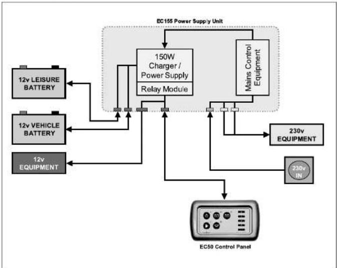
flowchart
graph TD
    A["12v LEISURE BATTERY"] --> B["150W Charger / Power Supply Relay Module"]
    C["12v VEHICLE BATTERY"] --> B
    D["12v EQUIPMENT"] --> B
    B --> E["Mains Control Equipment"]
    E --> F["230v EQUIPMENT"]
    F --> G["EC50 Control Panel"]
    G --> H["230v IN"]
    H --> B
    B --> I["EC155 Power Supply Unit"]
3 Power Supply Details
For the safe operation of all electrical equipment within your Leisure Vehicle it is important that you read and fully understand these instructions. If you are unsure of any point please contact your dealer / distributor for advice before use.
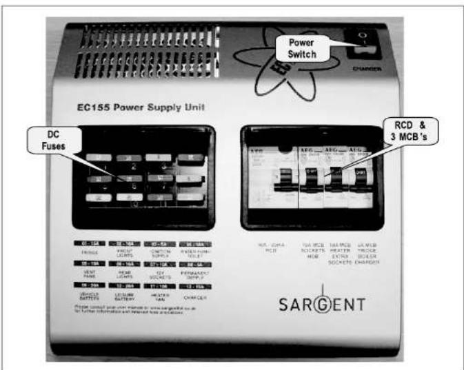
The following diagram shows the EC155PSU layout.
WARNING: Under heavy loads the EC155PSU case may become hot. ALWAYS ensure the ventilation slots have a clear flow of air. Do not place combustible materials against / adjacent to the EC155PSU. The PSU will shutdown if overheated and will restart automatically when cool
3.1 Battery Charger / Power Converter
The EC155PSU incorporates a fixed voltage battery charger / power converter. The battery charger / power converter also powers the leisure equipment when the mains supply is connected. This module supplies 13.8v DC to the leisure equipment up to a maximum of 12 Amps (165 Watts), therefore the available power is distributed between the leisure load and the battery, with the leisure load taking priority as per the following example:
| Leisure load Available | power for battery charging |
| 3A 9A | |
| 6A 6A | |
| 9A 3A | |
| 12A 0A |
3.2 Residual Current Device & miniature Circuit Breakers
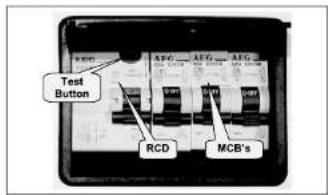
The Residual Current Device (RCD) is basically provided to protect the user from lethal electric shock. The RCD will turn off (trip) if the current flowing in the live conductor does not fully return down the neutral conductor, i.e. some current is passing through a person down to earth or through a faulty appliance.
To ensure the RCD is working correctly, the test button should be operated each time the vehicle is connected to the mains supply (see section 5.1)
The Miniature Circuit Breakers (MCB's) operate in a similar way to traditional fuses and are provided to protect the wiring installation from overload or short circuit. If an overload occurs the MCB will switch off the supply. If this occurs you should investigate the cause of the fault before switching the MCB back on.
The following table shows the rating and circuit allocation for the three MCB's
| MCB | Rating | Wire Colour | Description |
| 1 10 Amps | White | 230v | Sockets |
| 2 10 Amps | White (Yellow for heater) | Extra 230v | Sockets / Heater |
| 3 | 6 Amps | Black (Blue for water heater) | Fridge / Water Heater / 12v Charger (Internally connected) |
3.3 Fuses
WARNING: When replacing fuses always replace a fuse with the correct value. NEVER replace with a higher value / rating as this could damage the wiring harness or appliance. If a replacement fuse 'blows' do not keep replacing the fuse as you could damage the wiring harness or appliance. Please investigate the fault and contact your dealer.
The following table shows the fuse allocation for the 12 fuses fitted to the EC155PSU.
| Fuse Rating Fuse Colour Wire Colour Description | ||||
| 1 15 Amps Blue Red / Yellow Fridge | ||||
| 2 10 Amps Red Grey Front Lights | ||||
| 3 5 Amps Tan Yellow Green Ignition Supplies | ||||
| 4 10 Amps Red Green / Blue Water Pump / Toilet | ||||
| 5 10 Amps Red Black/Blue Ventilation Fans | ||||
| 6 10 Amps Red Pink Rear Lights | ||||
| 7 10 Amps Red Yellow / White 12v Sockets / TV Amplifier / Entertainment | ||||
| 8 5 Amps Tan Brown / Yellow Permanent Supply (Radio / Fridge) | ||||
| 9 20 Amps Yellow Brown / Green Vehicle Battery | ||||
| 10 | 20 Amps Yellow Brown / Blue Leisure Battery | |||
| 11 | 10 Amps Red Black/Red Heater Fan | |||
| 12 | 15 Amps Blue - Charger | |||
The following table shows details of the fuse(s) located at the Leisure battery.
| Fuse | Rating Fuse | Colour Wire Colour Description | ||
| Battery 1 | 20 Amps | Yellow | Brown / Blue | Fuse remotely located near battery |
3.4 Battery
A) Type / Selection
For optimum performance and safety it is essential that only a proprietary brand LEISURE battery is used with a typical capacity of 75 to 120 Ah (Ampere / hours). A normal car battery is NOT suitable. This battery should always be connected when the system is in use.
The EC155PSU is designed to charge standard lead acid leisure batteries, however it may be used with Gel batteries depending on their composition. Please consult the battery documentation for further advice.
The battery feed is fitted with an inline fuse between the battery and the electrical harness, and is usually located immediately outside the battery compartment or within 500mm of the battery. The maximum rating of this fuse is 20A per battery.
B) Installation & Removal
Always disconnect the 230v mains supply and turn the EC155PSU charger switch to the OFF (0) position before removing or installing the battery.
When connecting the battery, ensure that the correct polarity is observed (black is negative [-] and red is positive [+]) and that the terminals are securely fastened. Crocodile clips must not be used.
WARNING: Explosive gases may be present at the battery. Take care to prevent flames and sparks in the vicinity of the battery and do not smoke.
C) Operation / Servicing
Under normal circumstances it should not be necessary to remove the battery other than for routine inspection of the terminals and "topping up" of the battery fluid where applicable. Please see instructions supplied with the battery.
Note: Do not over discharge the battery. One of the most common causes of battery failure is when the battery is discharged below the recommended level of approximately 10v. Discharging a battery below this figure can cause permanent damage to one or more of the cells within the battery.
To prevent over discharge, the EC155PSU in conjunction with the EC50 series control panel incorporates a battery protect circuit that warns and then disconnects the batteries when they fall below the following conditions:
| Battery Voltage cut off | Action after cut off Notes | |
| Vehicle 10.9v Batter | selection is changed from Vehicle battery to Leisure battery. If the leisure battery is below 9v then a further warning will occur (see below). | This cut off level is designed to protect the vehicle battery from over discharge. The 10.9v level ensures there is sufficient power in the battery to run the vehicle electronics and start the vehicle. This cut off only applies to power drawn from the battery by the leisure equipment; it will not protect the battery if you leave the vehicle lights on. |
| Leisure 9v Power is turned off This is an emergency cut off level to protect the battery from severe damage. You should not rely on this cut off level during normal operation, but manage your power consumption to a discharge level of 10v. This cut off only applies to power drawn from the battery by the leisure equipment that is controlled by the control panel power switch; it will not protect the battery from discharge by the radio or other permanently connected equipment. | ||
4 Control Panel Details
4.1 Layout and Buttons
The following diagram shows the control panel layout and button functions (EC50 control panel).
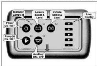
Note: to remove the decorative bezel, pull down and lift forward as indicated by the arrow.
4.2 Operation
The following
| Symbol | Function | Description |
 | Main 12v Power switch | This switch turns on (or off) the 12-volt power.As the power is turned on the Leisure battery is automatically selected and the LED display shows the battery voltage. |
 | Water Pump power switch | This switch turns on power to the internal water pump ready for use.It can be used to turn off the pump over night to avoid any noise from the pump. When the switch is on, the LED will show green. |
 | Light switch | This switch turns the ceiling lights on (or off). When the switch is on the LED will show green. |
 | Select LEISURE battery and display battery voltage | This switch is used to select the Leisure battery and to display the battery voltage level. Press once to select and display the voltage.This display will turn off automatically after 5 seconds.The LED next to the button will show that the battery has been selected.If the Leisure battery drops below 9v an alarm will trigger to warn you that the battery is low. This alarm lasts for 1 minute and then the power will be switched off to protect the battery. |
 | Select VEHICLE battery and display battery voltage | This switch is used to select the Vehicle battery and to display the battery voltage level. Press once to select and display the voltage.This display will turn off automatically after 5 seconds.The LED next to the button will show that the battery has been selected.If the Vehicle battery drops below 10.9v an alarm will trigger to warn you that the battery is low. This alarm lasts for 1 minute and then the battery selection will automatically switch over to the Leisure battery to protect the vehicle battery. |
4.3 System Disable
To meet EMC (Electro Magnetic Compatibility) directive 89/336/EEC the EC50 series control panel will shutdown, and the electrical accessories within the vehicle will be disconnected while the vehicle is in motion. When the engine is stopped the control panel returns to standby mode ready to be turned on by the power button.
4.4 Bar Graph Technical data
| LED Colour Voltage reading Water reading | |
| 5 Green 13.5 - 14.4 100% full | |
| 4 Green 12.5 - 13.5 75% full | |
| 3 Yellow 11.5 - 12.5 50% full | |
| 2 Yellow 10.5 - 11.5 25% full | |
| 1 Red k = 10.5 Less than 25% |
5 Operational & Safety Information
5.1 Connecting to the Mains supply
Safety checks
Connecting to the Mains supply - Safety checks For your safety it is IMPORTANT that you follow these connections instructions each time your Leisure Vehicle is connected to a mains supply.
A) Ensure suitability of the Mains Supply. Your Leisure Vehicle should only be connected to an approved supply that meets the requirements of BS7671. In most cases the site warden will hold information regarding suitability of supply. If using a generator you also need to comply with the requirements / instructions supplied with the generator. Please note that some electronic generators may not be compatible with your leisure system.
B) Switch the EC155PSU internal Power Converter OFF. Locate the red 'Charger' power switch on the EC155PSU and ensure the switch is in the OFF (0) position before connection to the mains supply.
C) Connect the Hook-up Lead. Firstly connect the supplied hook-up lead (orange cable with blue connectors) to the Leisure Vehicle and then connect to the mains supply.
D) Check Residual Current Device operation. Locate the RCD within the EC156PSU and ensure the RCD is switched on (lever in up position). Press the 'TEST' button and confirm that the RCD turns off (lever in down position). Switch the RCD back to the on position (lever in up position). If the test button failed to operate the RCD see section 5.2.
E) Check Miniature Circuit Breakers. Locate the MCB's within the EC155PSU (adjacent to the RCD) and ensure they are all in the ON (up) position. If any MCB's fail to latch in the on position see section 5.2.
F) Turn the EC155PSU ON. Locate the red power switch on the EC155PSU and turn to the ON (I) position. The switch will illuminate when turned on.
G) Check operation of equipment. It is now safe to check the operation of the 12v and 230v equipment.
5.2 Common Fault Table
| Fault Possible Cause Proposed Fix | ||
| No 230 volt output from PSU | Connecting lead between the site and Leisure Vehicle not connected | Check and connect lead as per 5.1C Check also input connector at the base of the EC155PSU |
| RCD switched off Reset RCD | as per 5.1D | |
| RCD not operating correctly | Check supply polarity; if the RCD continues to fail contact your Dealer, as there is probably an equipment or wiring fault. | |
| MCB switched off Reset MCB | by switching OFF (down position) then back ON (up position), if the MCB continues to fall contact your Dealer, as there is probably an equipment or wiring fault. | |
| No or deficient supply from site | Contact site Warden for assistance | |
| Other fault Contact your Dealer | ||
| Control Panel Problems | Control Panel has no display | Check batteries & fuses, turn EC155PSU charger switch on, and ensure mains supply is connected. Check control panel connecting lead at EC155PSU and behind Control Panel Contact your Dealer |
| 12v Power turns off Battery save feature has operated to protect the Vehicle battery and or the Leisure battery. See 3.4C Engine has been started, all equipment has been disconnected to meet EMC requirements. See 4.3 | ||
| Control Panel display corrupt / erratic function | Observe control panel handling instructions Control panel software may have crashed. Reboot control panel by turning off the EC155PSU charger switch and removing fuses 9 & 10 at the EC155PSU (2x20A fuses for leisure and vehicle batteries). Wait 30 seconds then replace the fuses and turn the charger switch on. (Alternatively, remove the bezel at the control panel by pulling down in the centre at the bottom, unplug the control panel multi-way connector, wait 30 seconds, then plug back in and reassemble.) | |
5.2 Common Fault Table
| Fault Possible Cause Proposed Fix | ||
| No 12 volt output from PSU | No 230v supply Check all above | |
| Charger not switched on Switch charger switch on (I) position, switch will illuminate | ||
| Battery not connected and / or charged | Install charged battery as per 3.4 | |
| Power switch on control panel not switched to ON | Turn power on at control panel | |
| Battery flat / Battery fuse blown | Recharge battery, check fuses, check charging voltage is present at battery | |
| Fuse blown Check all fuses are intact and the correct value fuse is installed as per fuse table | ||
| Equipment switched off / unplugged | Check equipment is switched on and connected to the 12v supply | |
| PSU overheated / auto shutdown operated | Reduce load on system. Allow PSU to cool down. PSU will automatically restart when cool. See section 3 | |
| Other fault Contact your Dealer | ||
| Pump not working | Fuse blown Replace fuse | |
| Pump turned off Turn pump on by pressing the pump button at the EC155 control panel (tap symbol) | ||
| Control Panel display corrupt / erratic function | Observe control panel handling instructions Control panel software may have crashed. Reboot control panel by turning off the EC155PSU charger switch and removing fuses 9 & 10 at the EC155PSU (2x20A fuses for leisure and vehicle batteries). Wait 30 seconds then replace the fuses and turn the charger switch on. (Alternatively, remove the bezel at the control panel by pulling down in the centre at the bottom, unplug the control panel multi-way connector, wait 30 seconds, then plug back in and reassemble.) | |
6 Technical Data & Approvals
6.1 Outline Specification
| INPUT 230v | 230 Volts / 0 to 12 Amps | + / - 10% |
| OUTPUT 230v | RCD protected, 3 x MCB outputs of 10, 10 and 6A via 2 x 9 way connectors | |
| INPUT 12v | 2 x 20A battery inputs via a single 9 way connector | |
| OUTPUT 12v | 20A total output via 4 x 16A switched channels protected by 12 fused outputs via a 12 way connector | |
| Integrated CHARGER | Input 220-240 Volts AC +/- 10%, Frequency 50 Hz +/- 6%, Current 3A max.DC Output 13.8 Volts nominal, Current 12 Amps max (155 Watts) | |
| Signal INPUT | 1 x Engine running via PSU connector (4 x Fresh water level, 1 x Waste water level on EC51 version) | Fresh water negative sensedWaste water 5v sensed |
| Data IN / OUT | Data communication and power to Control Panel via 8 way RJ45 connector | Contact your Dealer |
| IP rating | IP31 | |
| Operating temperature | Ambient 0 to 35° CentigradePSU case temperature with full load 65°C Max | Automatic shutdown and restart if overheated / overloaded |
6.2 Dimensions
| EC155PSU | Overall size (HxWxD) 260 x 273 x 110mm | Fixing centres 262 x 224mm |
| Clearances 75mm above, 20mm below, 50mm left & right | Weight 2.2 Kg | |
| EC100 CONTROL PANEL | Overall size (HxWxD) 80 x 140 x 30mm | Fixing centres 123mm |
| Cut-out size (HxW) 60 x 110mm | Weight 100 g |
6.3 Approvals
System: BSEN 1648-1, BSEN1648-2 compliant, BS7671: 2008 compliant
Residual Current Device: RCD 40A 30mA trip to BS EN 61008
Miniature Circuit Breakers: MCB's (10 & 6A) type C 6000A breaking capacity to BSEN 60898
Electro Magnetic Compatibility (EMC) directive 89/336/EEC
Integrated Charger: BS EN 60335-1/2.29, 89/336/EEC, IEC61000-3.2/3:1995, EMC certificate 5172TC 3rd party tested.
6.4 Declaration of Conformity
Equipment: Leisure Power Control System Model name: EC155PSU / EC50CP / EC51CP / EC52CP
I hereby declare that the equipment named above has been designed to comply with the relevant sections of the above referenced approvals. The unit complies with all essential requirements of the Directives.
| Signed: Name: Position: Manufacturer: | |||
| I L Sargent Technical Director Sargent Electrical Services LtdUnit 39, Tokenspire BusinessPark, Woodmansey, BeverleyEast Yorkshire, United Kingdom | |||
| Date: | |||
6.5 Electrical Connection
A) Battery Input Connector
| Pin Function Fuse Wire Colour | |||
| 1 Fridge 12V output 1 RED / YELLOW | |||
| 2 Battery common earth 1 - | WHITE / ORANGE | ||
| 3 Battery common earth 2 - | WHITE / ORANGE | ||
| 4 Auxiliary 12V output | 2 $LATE / RED | ||
| 5 Vehicle battery input 1 | 9 BROWN / GREEN | ||
| 6 Vehicle battery input 2 | 9 BROWN / GREEN | ||
| 7 Fridge power in / Engine run | - | RED | |
| 8 Leisure battery input 1 | 10 | BROWN / BLUE | |
| 9 Leisure battery input 2 | 10 | BROWN / BLUE | |
B) 12v Output Connector
| Pin Function Fuse | Wire Colour | ||
| 1 Radio | 8 | BROWN / YELLOW | |
| 2 12v Sockets 1 | 7 | YELLOW / WHITE | |
| 3 12v Sockets 2 | 7 | YELLOW / WHITE | |
| 4 Ignitions | 3 | YELLOW / WHITE | |
| 5 Front Lights 1 | 2 | SLATE | |
| 6 Front Lights 2 | 2 | SLATE | |
| 7 Heater fan | 11 | BLACK / RED | |
| 8 Rear Lights 1 | 6 | PINK | |
| 9 Rear Light 2 | 6 | PINK | |
| 10 | Fans | 5 | |
| 11 | Toilet Pump | 4 | |
| 12 | Pump | 4 |
C) 230v mains Input connector
| Pin Function Wire Colour | ||
| 1 Not used - | ||
| 2 Earth GREEN / YELLOW | ||
| 3 Live BROWN | ||
| 4 Neutral BLUE |
D) 230v mains output connector (2 off connectors wired identical)
| Pin Function MCB Wire Colour | ||||
| 1 Live 3 BROWN | ||||
| 2 Earth 3 GREEN / YELLOW | ||||
| 3 Neutral 3 BLUE | ||||
| 4 Live 2 BROWN | ||||
| 5 Earth 2 GREEN / YELLOW | ||||
| 6 Neutral 2 BLUE | ||||
| 7 Live 1 BROWN | ||||
| 8 Earth 1 GREEN / YELLOW | ||||
| 9 Neutral 1 BLUE | ||||
While every effort has been made to ensure the accuracy and completeness of this document, no guarantee is given against errors or omissions. This document may be updated / improved over time therefore please check with your dealer / supplier for update information or visit www.sargentitld.co.uk
- Contents
- Specification
- Wiring Diagrams
- \* Estimated
- Wiring DiagramsW
- Sprite Lite range - 13 pin socket Sprite Lite range - Cable colours
- Bulb Replacement
- SPRITE ROAD LIGHT BULB ACCESS
- REAR ROAD LIGHT CLUSTERS (STOP / TAIL / INDICATOR / REVERSE / FOG)
- UPPER REAR SIDE POSITION LAMPS (RED / CLEAR LENSE)
- REAR CENTRAL FOG LIGHT
- NUMBER PLATE LAMPS
- FRONT MARKER / POSITION LAMPS
- EC155 Power Control System
- Key Features
- System Overview
- Power Supply Details
- Battery Charger / Power Converter
- Fuses
- Battery
- A) Type / Selection
- B) Installation & Removal
- C) Operation / Servicing
- Control Panel Details
- Layout and Buttons
- Operation
- System Disable
- Operational & Safety Information
- Connecting to the Mains supply
- Safety checks
- Technical Data & Approvals
- Approvals
- Declaration of Conformity
- Electrical Connection
Brand : Swift
Model : Sprite Lite (2012)
Category : Caravan