
KV-CM40U - Uncategorized JVC - Free user manual and instructions
Find the device manual for free KV-CM40U JVC in PDF.


| Product Type | Universal Backup Camera with Multiple Mounting Options |
| Brand | JVC |
| Model | KV-CM40U |
| Image Sensor | 1/3-inch color CMOS |
| Number of Pixels | Approx. 470,000 pixels |
| Lens | Wide angle, f=1.96 mm, F1.8 |
| Angle of View (Horizontal) | 125° |
| Angle of View (Vertical) | 103° |
| Minimum Illumination | 0.1 lux |
| Video Output | 1.0 Vp-p / 75 ohms |
| Water and Dust Protection | IP69K |
| Operating Temperature | -30°C to +70°C |
| Operating Voltage | DC 9.0 V - 16.0 V |
| Camera Dimensions (W×H×D) | 21.9 × 21.9 × 24.4 mm (7/8 × 7/8 × 15/16 in) |
| Camera Weight | 28.3 g (1.0 oz) without cable |
| Power Cord Length | 7.5 m (24.6 ft) |
| Camera Cord Length | 1.5 m (4.92 ft) |
| Mounting Options | Square Mount, Metal Mount, Rubber Mount, License Plate Mount |
| Mirror Image | Default for rear view; can be disabled for front camera use |
| Parking Guide Lines | Displayed by default; can be hidden for front camera use |
| Kit Contents | Camera, Power cord (7.5 m), Grommet, Square Mount, Cover, Camera bracket, Rubber ring, Screws, Double-side tape |
| Certifications | FCC Part 15 Class B, ICES-003, IP69K |
Frequently Asked Questions - KV-CM40U JVC
User questions about KV-CM40U JVC
0 question about this device. Answer the ones you know or ask your own.
Ask a new question about this device
Download the instructions for your Uncategorized in PDF format for free! Find your manual KV-CM40U - JVC and take your electronic device back in hand. On this page are published all the documents necessary for the use of your device. KV-CM40U by JVC.
USER MANUAL KV-CM40U JVC
UNIVERSAL CAMERA WITH MULTIPLE MOUNTING OPTIONS
INSTRUCTION MANUAL
CAMÉRA UNIVERSELLE AVEC PLUSIEURS OPTIONS DE MONTAGE
MODE D'EMPLOI
CÁMARA UNIVERSAL CON OPCIONES MÚLTIPLES DE MONTAJE
Please read this manual carefully to ensure proper use before using this product. It is especially important that you read and observe WARNING and CAUTION in this manual. Please keep the manual in a safe and accessible place for future reference.
WARNING
To prevent injury or fire, take the following precautions:
- To prevent a short circuit, never put or leave any metallic objects (such as coins or metal tools) inside the unit.
- Installation and wiring of this product require specialist skill and experience. To assure your safety, please request a specialist technician to install the unit.
- When you make a hole to install the camera, check the location of pipes, tanks and wiring and avoid touching them. Otherwise it may cause the fire.
- When you make a hole with a drill, use goggles to protect your eyes.
- To avoid the danger of accidental ingestion, keep any small objects such as screws away from children. If you think it might have been swallowed, seek immediate medical attention.
CAUTION
To prevent damage to the product, take the following precautions:
• Make sure to ground the unit to a negative 12V DC power supply.
- When replacing a fuse, only use a new fuse with the prescribed rating. Using a fuse with the wrong rating may cause your unit to malfunction.
- Do not use your own screws. Use only the screws provided. If you use the wrong screws, you could damage the unit.
- Do not wash your car with an automatic car wash or high-pressure water as it may result in water entering the camera or the camera falling off.
NOTE
- Connection to a TV with an RCA video input is possible, but confirm whether the TV you use has a reverse gear connection function.
- This product is designed to supplement the driver's view, but the camera images do not show all dangers and obstacles. If you install rear view camera, be sure to look behind you when reversing to confirm the view.
- This product features a wide-angle lens, so the near view is wide and the far view is narrow, which may create a false sense of distance. Be sure to look behind you when reversing to confirm the view.
- The position of guide line displayed on the monitor may differ from actual condition. Please take the actual guide line as reference and check with eyes.
- Check camera bracket and mount installation before driving. Are the screws loose?
- Is the camera bracket firmly secured?
- If the camera comes loose while you are driving it may cause an accident.
- Before finally installing the unit, connect the wiring temporarily, making sure it is all connected up properly, and the unit and the system work.
- When mounting this unit, make sure none of the leads are trapped between this unit and the surrounding metalwork or fittings.
• Before drilling any mounting holes always check behind where
you want to drill the holes. Do not drill into the gas line, brake line, electrical wiring or other important parts.
- If this unit is installed in the passenger compartment, anchor it securely so it does not break free while the car is moving, and cause injury or an accident.
- If this unit is installed under a front seat, make sure it does not obstruct seat movement. Route all leads and cords carefully around the sliding mechanism so they do not get caught or pinched in the mechanism and cause a short circuit.
Care and maintenance
- When the product gets dirty, wipe dry with a silicon cloth or soft cloth. If it is seriously stained, remove stain with a cloth moistened with a neutral cleaner and then wipe the cleaner away. Do not use a hard cloth and/or a volatile substance such as lacquer thinner or alcohol, scratches, deformation, degradation and/or damage may result.
- When a lens component gets dirty, wipe gently with a soft cloth moistened with water. Do not rub with a dry cloth to prevent scratching the lens.
Installation Procedure
1 To prevent a short circuit, remove the key from the ignition and disconnect the ⊖ battery.
2 Make the proper input and output wire connections for each unit.
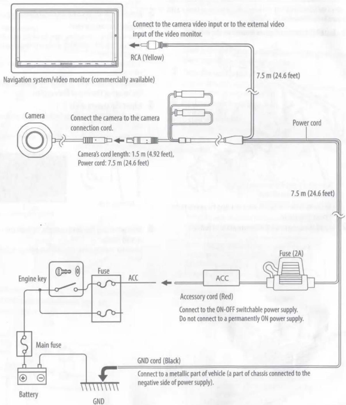
3 Connect the power cord wires in the following order: GND, ACC, and camera connecting cord.
4 Install the unit in your car.
5 Reconnect the ⊖ battery.
WARNING
- If you connect the ignition wire (Red) to the car chassis (Ground), you may cause a short circuit, that in turn may start a fire. Always connect the ignition wire to the power source running through the fuse box.
- Do not cut out the fuse from the ignition wire (Red). The power supply must be connected to the wire via the fuse.
CAUTION
- If your car's ignition does not have an ACC position, connect the ignition wires to a power source that can be turned on and off with the ignition key. If you connect the ignition wire to a power source with a constant voltage supply, as with battery wires, the battery may die.
- If the fuse blows, first make sure the wires aren't touching to cause a short circuit, then replace the old fuse with one with the same rating.
- Insulate unconnected wires with vinyl tape or other similar material. To prevent a short circuit, do not remove the caps on the ends of the unconnected wires or the terminals.
- After the unit is installed, check whether the brake lamps, blinkers, wipers, etc. on the car are working properly.
• Install so that it does not obstruct the rear field of view.
• Install so that it does not protrude from the side of the car. - Do not perform installation in rain or fog.
- When humidity is high, dry the surface to which the unit is to be attached before installing.
- Moisture on the attachment surface reduces adhesive strength, which may lead to the unit coming off.
- Do not attach the camera bracket to areas on the car body treated with fluorocarbon resin, or glass.
• These may result in the camera falling off.
- Do not subject the camera to unnecessary force.
- Thoroughly clean where tape is used for sticking on the unit.
- Refer to the Instruction's manual for details on connecting the other units, then make connections correctly.
- Secure the wiring with cable clamps or adhesive tape. To protect the wiring, wrap adhesive tape around them where they lie against metal parts.
- Route and secure all wiring so it cannot touch any moving parts, such as the gear shift, handbrake and seat rails.
- Do not route wiring in places that get hot, such as near the heater outlet. If the insulation of the wiring melts or gets torn, there is a danger of the wiring short-circuiting to the vehicle body.
- When replacing the fuse, be sure to use only fuse of the rating prescribed on the fuse holder.
- To minimize noise locate the TV antenna cable, radio antenna cable and RCA cable as far away from each other as possible.
- Lay the cords by avoiding high-temperature areas. Use corrugated tubes for wiring inside the engine room. If a cord contacts a high-temperature area of the vehicle, the coating may melt and cause short-circuiting, which may lead to a fire or electric shock hazard.
Kit Components
Camera .....1
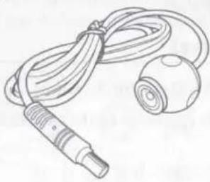
natural_image
Line drawing of a medical or laboratory device with a coiled cable and a spherical device (no text or symbols)Power cord (7.5 m / 24.6 ft).....1
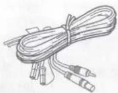
natural_image
Illustration of a coiled cable with two connectors (no text or symbols)Grommet.....1
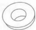
Square Mount .....1
Cover .....1
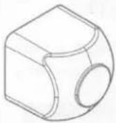
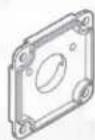
Camera bracket .....1
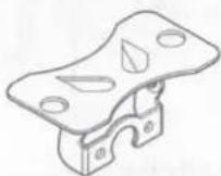
Rubber ring .....1

Screw (φ2 × 4 mm) (For cover) .....4

Screw (φ2 × 5 mm) (For camera and bracket) .....2

Screw (φ3 × 10 mm) (For car body) .....2
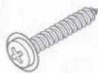
Double-side adhesive tape.....1
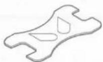
(For car body) ......2
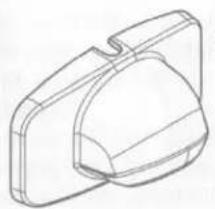
Cover .....1
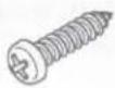
Screw (φ2 × 4 mm)
(For cover) .....4

Double-side adhesive tape.....1
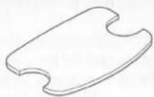
Rubber Mount .....1
natural_image
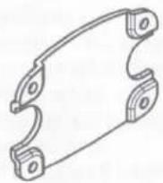
Technical line drawing of a mechanical component with a curved cutout (no text or symbols)License Plate Mount .....1
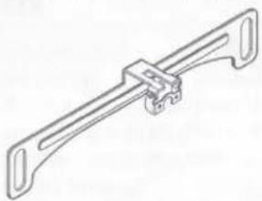
natural_image
Technical line drawing of a mechanical clamp or bracket (no text or symbols)Recommended Installation Position
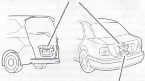
Examples of correct camera installation on the rear of the vehicle
Top of the license plate:
Square Mount/Metal Mount/Rubber Mount/License Plate Mount
natural_image
Line drawings of two cars, one open showing front engine compartment and the other side view with cable (no text or symbols)The underside of the license plate:
Metal Mount/Rubber Mount
When you decide on the camera installation position, clean the surface of the installation position. Using a commercially available cleaner, wipe the dirt, moisture, and oil away from the surface on which the camera bracket is to be attached.
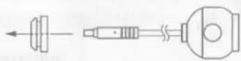
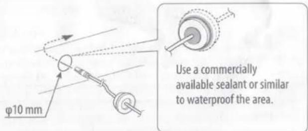
Using a grommet
1 Drill a hole of 10 mm for the wiring.
2 Pass the cable connector on the camera side through it.
3 Waterproof the grommet area on the inner side of the back door with a commercially available sealant or similar.
Installing the Camera – Square Mount
Tighten the screws firmly with the recommended torque, as there is a risk of parts being damaged or parts falling.
1 Install the camera on the mount as follows.
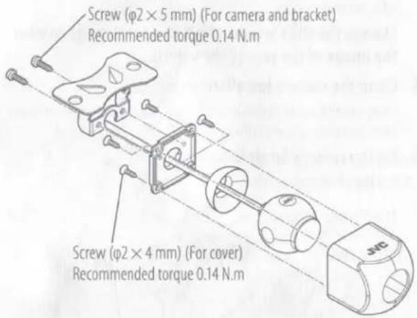
Mount so that the "JVC" logo appears at the top.
2 Fix the camera temporarily with tape, etc.
Using a piece of tape, etc., fix the camera temporarily.
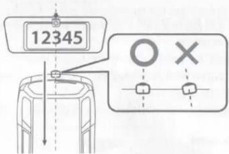
Install the camera at the center of the vehicle and not to hide the license plate. And also install straight toward the forward/reverse direction of the vehicle. Be careful not to lean the camera toward other directions of the vehicle, etc.
3 Complete all of the required connections.
4 Display the camera view.
Before watching the camera view, apply the parking brake and chock the wheels so that the vehicle will not move. Otherwise, an unexpected accident may result.
For displaying the camera view, read the instruction manual for your video monitor.
Change the shift lever to the R (Reverse) range to view the image of the rear of the vehicle.
5 Adjust the camera angle.
When adjusting the camera angle, be careful not to stretch the camera cord.
Adjust the angle so that the rear of the vehicle or the bumper can be seen at the bottom of the monitor.
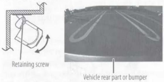
6 After adjusting the camera angle, tighten the retaining screws firmly.
Inspect the retaining screws at times. If they are loose, tighten them firmly.
7 Fix the camera firmly in position.
1) Peel off the paper liners from the double-side adhesive tape and attach it. After attaching, push the camera bracket with your finger to ensure close adhesion.
Do not touch the adhesive surface with your hand or peel and reattach the tape, as these will degrade the adhesive force and may cause the camera bracket to be detached.
2) Secure the mount on the vehicle body using the screws (For car body).
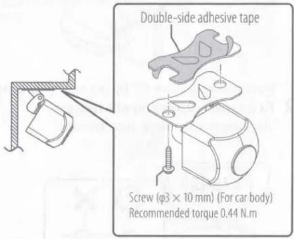
Installing the Camera – Metal Mount/Rubber Mount
1 Install the camera on the mount as follows.
For Metal Mount
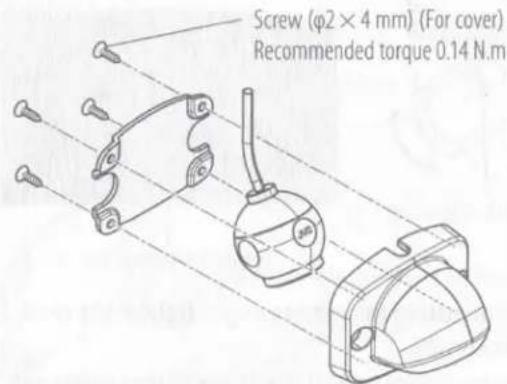
Mount the camera so that the "JVC" logo faces away from the ground.
For Rubber Mount
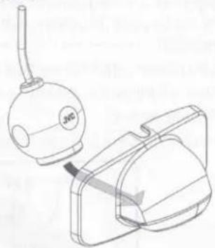
natural_image
Technical line drawing of a mechanical device with a bulb and housing (no text or symbols)Mount the camera so that the "JVC" logo faces away from the ground.
2 Fix the camera temporarily with tape, etc.
Using a piece of tape, etc., fix the camera temporarily.
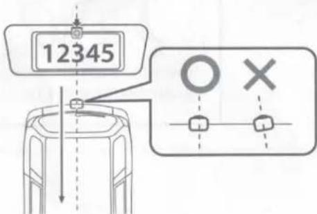
Install the camera at the center of the vehicle and not to hide the license plate. And also install straight toward the forward/reverse direction of the vehicle. Be careful not to lean the camera toward other directions of the vehicle, etc.
3 Complete all of the required connections.
4 Display the camera view.
Before watching the camera view, apply the parking brake and chock the wheels so that the vehicle will not move. Otherwise, an unexpected accident may result.
For displaying the camera view, read the instruction manual for your video monitor.
Change the shift lever to the R (Reverse) range to view the image of the rear of the vehicle.
5 Clean the camera installation surface.
Using a commercially available cleaner, wipe dirt, moisture and oil away from the surface on which the camera bracket is to be attached.
6 Fix the camera firmly in position.
For Metal Mount
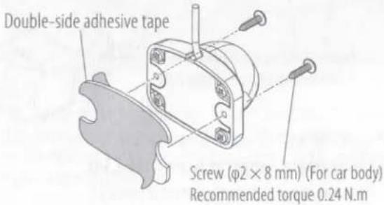
1) Peel off the paper liners from the double-side adhesive tape and attach it. After attaching, push the Metal Mount with your finger to ensure close adhesion.
Do not touch the adhesive surface with your hand or peel and reattach the tape, as these will degrade the adhesive force and may cause the Metal Mount to be detached.
2) Secure the mount on the vehicle body using the screws (For car body).
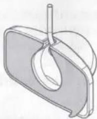
For Rubber Mount
natural_image
Technical line drawing of a mechanical component with a central rod and curved housing (no text or symbols)Peel off the paper liner from the double-side adhesive tape on the Rubber Mount and attach it. After attaching, push the Rubber Mount with your finger to ensure close adhesion.
Do not touch the adhesive surface with your hand or peel and reattach an attached tape, as these will degrade the adhesive force and may cause the Rubber Mount to be detached.
Installing the Camera – License Plate Mount
Tighten the screws firmly with the recommended torque, as there is a risk of parts being damaged or parts falling.
1 Install the camera (Square Mount) on the mount.
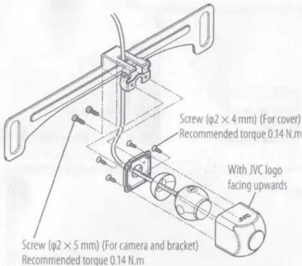
- Be careful not to overtighten when attaching the camera to the License Plate Mount.
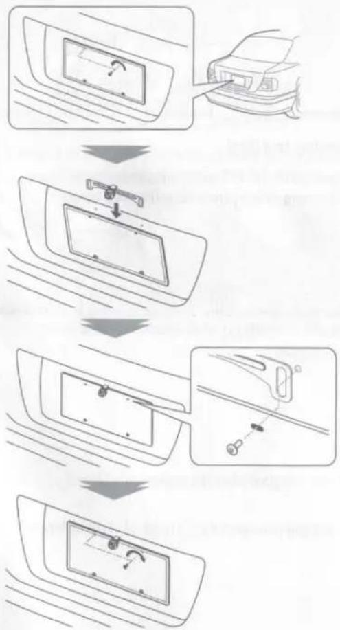
2 Install the camera on the license plate as follows.
flowchart
graph TD
    A["Door Opening"] --> B["Adjustment to Panel"]
    B --> C["Close-up of Door"]
    C --> D["Close-up of Panel"]
    D --> E["Final Adjustment"]
- Make sure the cable does not touch the edge of the license plate or frame during installation.
3 Complete all of the required connections.
4 Display the camera view.
Before watching the camera view, apply the parking brake and chock the wheels so that the vehicle will not move. Otherwise, an unexpected accident may result.
For displaying the camera view, read the instruction manual for your video monitor..
Change the shift lever to the R (Reverse) range to view the image of the rear of the vehicle.
5 Adjust the camera angle.
When adjusting the camera angle, be careful not to stretch the camera cord.
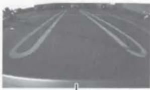
Adjust the angle so that the rear of the vehicle or the bumper can be seen at the bottom of the monitor.
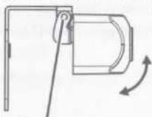
Retaining screw
natural_image
Grayscale photo of a paved road with curved tire tracks (no visible text or symbols)Vehicle rear part or bumper
6 After adjusting the camera angle, tighten the retaining screws firmly.
Inspect the retaining screws at times. If they are loose, tighten them firmly.
Basic Connections
flowchart
graph TD
    A["Camera"] --> B["Connect the camera to the camera connection cord"]
    B --> C["Camera's cord length: 1.5 m (4.92 feet), Power cord: 7.5 m (24.6 feet)"]
    C --> D["Power cord"]
    D --> E["Fuse (2A)"]
    E --> F["ACC"]
    F --> G["Main fuse"]
    G --> H["Battery"]
    H --> I["GND"]
    I --> J["GND cord (Black)"]
    J --> K["Connect to a metallic part of vehicle (a part of chassis connected to the negative side of power supply)."]
    style A fill:#f9f,stroke:#333
    style B fill:#ccf,stroke:#333
    style C fill:#cfc,stroke:#333
    style D fill:#fcc,stroke:#333
    style E fill:#cff,stroke:#333
    style F fill:#ffc,stroke:#333
    style G fill:#cfc,stroke:#333
    style H fill:#fff,stroke:#333
    style I fill:#fff,stroke:#333
    style J fill:#fff,stroke:#333
    style K fill:#fff,stroke:#333
CAUTION
- If the engine key of your vehicle does not have the ACC position, branch the wire energized when the engine key is ON and connect it to the ACC position of the fuse box.
- Before proceeding to connections, make sure that the engine key is not inserted and disconnect the terminal of the battery to prevent the short-circuiting incident.
Specifications
Using the Camera as the Front Camera
You can also use the camera as the front camera.
Follow the Step below.
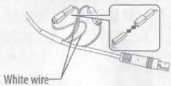
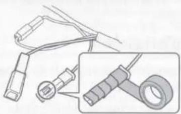
1 Disconnect the bullet terminal of the white wire to cancel the horizontal flip screen.
The screen turns to the normal orientation screen.
2 Disconnect the bullet terminal of the green wire to hyde the Parking Line.
The parking line is disappeared from the screen.
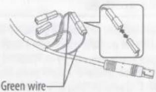
After disconnecting the terminal, wrap the terminal with an insulating tape as illustrated below.
natural_image
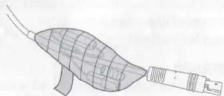
Technical line drawing of a medical or laboratory device with connectors and a magnified inset showing internal components (no text or symbols)- To prevent a rattling noise, wrap the all bullet terminals with an insulating tape as illustrated below.
natural_image
Diagram of a medical device with a curved body and attached rod, showing internal structure (no text or symbols)Camera Unit
Image Sensor: 1/3-inch color CMOS sensor
Lens: Wide angle, Focal length f=1.96 mm, F value 1.8
Angles of view
Horizontal: 125°
Vertical: 103°
Water-proof & Dust-proof: IP69K
Number of pixels: Approx. 470,000 pixels
Minimum illumination: 0.1 lx
Video output: 1.0 Vp-p/75Ω
Operation temperature: -30 °C to +70 °C
Operating voltage: DC 9.0 V - 16.0 V
Dimensions (W×H×D): 21.9 × 21.9 × 24.4 mm
$$ 7 / 8 \times 7 / 8 \times 1 5 / 1 6 \text { inch } $$
Weight: 28.3 g (1.0 oz) (without cable)
Mounting Unit
Square Mount
Dimensions (W×H×D): 25.9 × 25.9 × 24.9 mm
$$ 1 \times 1 \times 1 \text { inch } $$
Weight: 31.6 g (1.1 oz)
Metal Mount
Dimensions (W×H×D): 40.4 × 30.5 × 26.4 mm
$$ 1 - 9 / 1 6 \times 1 - 3 / 1 6 \times 1 - 1 / 1 6 \text { inch } $$
Weight: 27.8 g (1.0 oz)
Rubber Mount
Dimensions (W×H×D): 54.2 × 31.7 × 26.3 mm
$$ 2 - 1 / 8 \times 1 - 1 / 4 \times 1 - 1 / 1 6 \text { inch } $$
Weight: 9.9 g (0.3 oz)
License Plate Mount
Dimensions (W×H×D): 196.1 × 35.1 × 29.1 mm
$$ 7 - 3 / 4 \times 1 - 3 / 8 \times 1 - 1 / 8 \text { inch } $$
Weight: 49.3 g (1.7 oz)
- Mirror image means that the video image inverts the left and right just like the image seen on the rearview mirror or a side mirror.
• Specifications subject to change without notice.
For Canada
CAN ICES-3(B)/NMB-3(B)
For U.S.A
FCC CAUTION
Changes or modifications not expressly approved by the party responsible for compliance could void the user's authority to operate the equipment.
NOTE: This equipment has been tested and found to comply with the limits for a Class B digital device, pursuant to part 15 of the FCC Rules. These limits are designed to provide reasonable protection against harmful interference in a residential installation. This equipment generates, uses and can radiate radio frequency energy and, if not installed and used in accordance with the instructions, may cause harmful interference to radio communications. However, there is no guarantee that interference will not occur in a particular installation. If this equipment does cause harmful interference to radio or television reception, which can be determined by turning the equipment off and on, the user is encouraged to try to correct the interference by one or more of the following measures:
- Reorient or relocate the receiving antenna.
- Increase the separation between the equipment and receiver.
- Connect the equipment into an outlet on a circuit different from that to which the receiver is connected.
- Consult the dealer or an experienced radio / TV technician for help.
Supplier's Declaration of Conformity
Trade Name: JVC
Products: UNIVERSAL CAMERA WITH MULTIPLE
MOUNTING OPTIONS
Model Name: KV-CM40U
Responsible Party: JVCKENWOOD USA CORPORATION
4001 Worsham Avenue,
Long Beach, CA 90808, U.S.A.
PHONE: 1-800-252-5722
THIS DEVICE COMPLIES WITH PART 15 OF THE FCC RULES. OPERATION IS SUBJECT TO THE FOLLOWING TWO CONDITIONS:
(1) THIS DEVICE MAY NOT CAUSE HARMFUL INTERFERENCE, AND
(2) THIS DEVICE MUST ACCEPT ANY INTERFERENCE RECEIVED,
INCLUDING INTERFERENCE THAT MAY CAUSE UNDESIRED
OPERATION.
For Argentina
- INSTRUCTION MANUAL
- MODE D'EMPLOI
- WARNING
- To prevent injury or fire, take the following precautions:
- CAUTION
- To prevent damage to the product, take the following precautions:
- NOTE
- Care and maintenance
- Installation Procedure
- Kit Components
- Recommended Installation Position
- Using a grommet
- Installing the Camera – Square Mount
- Install the camera on the mount as follows.
- Fix the camera temporarily with tape, etc.
- Complete all of the required connections.
- Display the camera view.
- Adjust the camera angle.
- After adjusting the camera angle, tighten the retaining screws firmly.
- Fix the camera firmly in position.
- Installing the Camera – Metal Mount/Rubber Mount
- Clean the camera installation surface.
- Fix the camera firmly in position.
- Installing the Camera – License Plate Mount
- Specifications
- Using the Camera as the Front Camera
- Disconnect the bullet terminal of the white wire to cancel the horizontal flip screen.
- Disconnect the bullet terminal of the green wire to hyde the Parking Line.
- Camera Unit
- Mounting Unit
- For Canada
- CAN ICES-3(B)/NMB-3(B)
- For U.S.A
- FCC CAUTION
- Supplier's Declaration of Conformity
- For Argentina
Brand : JVC
Model : KV-CM40U
Category : Uncategorized