OVEM-05-H-B-QO-ON-N-2P - Compressor Festo - Free user manual and instructions
Find the device manual for free OVEM-05-H-B-QO-ON-N-2P Festo in PDF.


| Product Type | Vacuum Generator (Compressor) |
| Brand | Festo |
| Model | OVEM-05-H-B-QO-ON-N-2P |
| Category | Compressor |
| Nozzle Nominal Width | 0.45 mm |
| Operating Pressure | 2…8 bar |
| Pressure Measuring Range | -1…0 bar |
| Overload Pressure at Vacuum Port | ≤5 bar |
| Nominal Operating Voltage | 24 V DC ±15% |
| Max. Output Current per Switching Output | 100 mA |
| Switching Outputs | 2 PNP |
| Switching Inputs | 1 digital (suction) |
| Display | 4-digit alphanumeric LCD with segment bars |
| Protection Class | III (PELV) |
| Degree of Protection | IP65 |
| Ambient Temperature | 0…50 °C |
| Housing Material | Die-cast aluminium, PA reinforced |
| Seal Material | NBR, HNBR |
| Mounting | Direct mounting (side or back), H-rail, or mounting bracket |
| Certifications | c UL us listed (OL), RCM, KC |
| Air Saving Function | Yes (reduces air consumption during evacuation) |
| Auto-Drop Function | Yes (automatic ejector pulse after suction signal change) |
| Diagnostics | Monitors evacuation/pressurisation times, error codes displayed |
| Manual Override | Mechanical and electrical |
Frequently Asked Questions - OVEM-05-H-B-QO-ON-N-2P Festo
User questions about OVEM-05-H-B-QO-ON-N-2P Festo
0 question about this device. Answer the ones you know or ask your own.
Ask a new question about this device
Download the instructions for your Compressor in PDF format for free! Find your manual OVEM-05-H-B-QO-ON-N-2P - Festo and take your electronic device back in hand. On this page are published all the documents necessary for the use of your device. OVEM-05-H-B-QO-ON-N-2P by Festo.
USER MANUAL OVEM-05-H-B-QO-ON-N-2P Festo
natural_image
Technical line drawing of a mechanical device with mounting holes and internal components (no text or symbols)FESTO
Operating instructions

8125662
2020-05h
[8125664]
Translation of the original instructions
Table of contents
1 About this document.... 5
1.1 Applicable documents.... 5
2 Safety....5
2.1 Safety instructions.... 5
2.2 Intended use.... 5
2.3 UL certification.... 5
3 Further information.... 6
4 Service....6
5 Product overview.... 6
5.1 Product design.... 7
5.1.1 Product variants....7
5.1.2 Display components.... 10
5.2 Function.... 14
5.2.1 Switching functions.... 15
5.2.2 Valve control....16
5.2.3 Air saving function....17
5.2.4 Optimisation of the transport time....18
5.2.5 Monitoring and diagnostics.... 18
5.2.6 Measured variables.... 19
5.2.7 Teach function.... 20
5.2.8 Operating statuses and menu structure....21
6 Assembly.... 25
7 Installation.... 28
7.1 Pneumatic installation.... 28
7.2 Electrical installation.... 30
8 Commissioning.... 32
8.1 Commissioning the vacuum generator.... 32
8.2 Setting the intensity of the ejector pulse.... 33
9 Operation and use.... 34
9.1 Setting the ejector pulse duration.... 34
9.2 Configuring switching outputs.... 35
9.3 Setting the switching characteristics of a switching output.... 35
9.4 Set diagnostic message channel.... 36
9.5 Teach-in switching point.... 37
9.6 Deleting minimum or maximum pressure value.... 37
9.7 Setting critical limits for the evacuation and air supply times....38
9.8 Teaching evacuation and air supply time.... 38
9.9 Displaying evacuation and air supply times.... 39
9.10 Deleting evacuation and air supply times.... 39
9.11 Mechanical manual override.... 40
9.12 Electrical manual override....40
9.13 Activating the security code....41
9.14 Switching air saving function on or off....41
9.15 Restore factory settings....41
10 Maintenance and care.... 42
11 Fault clearance....43
11.1 Diagnostic levels....43
11.2 Error messages and error codes.... 44
11.3 Malfunctions....45
12 Disassembly....46
13 Disposal....47
14 Technical data.... 47
1 About this document
1.1 Applicable documents

All available documents for the product → www.festo.com/sp.
| Document Product Contents | ||
| Instruction manual Manifold rail OABM-P Assembly |
Tab. 1 Applicable documents
2 Safety
2.1 Safety instructions
– The product may only be used in its original status without unauthorised modifications.
- Only use the product if it is in perfect technical condition.
– Use the product only inside buildings.
- Take into consideration the ambient conditions at the location of use.
- The product is intended for use in industrial environments. This product can generate high frequency malfunctions, which may make it necessary to implement interference suppression measures in residential areas.
- Observe the specifications on the product labelling.
– Comply with all applicable national and international regulations.
- Observe the local regulations for environmentally friendly disposal.
2.2 Intended use
The intended use of the product is to generate a vacuum.
2.3 UL certification
In combination with the UL inspection mark on the product, the information in this section must also be observed in order to comply with the certification conditions of Underwriters Laboratories Inc. (UL) for USA and Canada.
| UL approval information | |
| Product category code QUYX (USA) | QUYX7 (Canada) |
| File number E322346 | |
| Standards taken into account UL 61010-1 | C22.2 No. 61010-1 |
| UL symbol | c US LISTED |
Further information
The unit shall be supplied by a power source which fulfils the requirements on a limited-energy circuit in accordance to IEC/EN/UL/CSA 61010-1 or on a Limited Power Source (LPS) in accordance to IEC/EN/UL/CSA 60950-1 or IEC/EN/UL/CSA 62368-1 or a Class 2 circuit in accordance to NEC or CEC.
3 Further information
- Accessories → www.festo.com/catalogue.
– Spare parts → www.festo.com/spareparts.
4 Service
Contact your regional Festo contact person if you have technical questions → www.festo.com.
5 Product overview
5.1 Product design
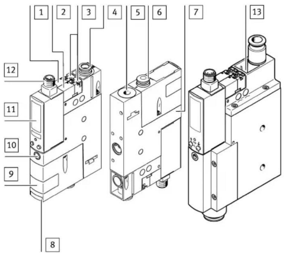
1 Solenoid valve for ejector pulse (Eject)
2 Solenoid valve for vacuum
3 Mechanical manual override of the solenoid valves
4 Supply port (1)
5 Exhaust port/silencer (3)
6 Vacuum port (6)
7 Housing with mounting holes
Fig. 1 Operating elements and connections
8 Gate valve for changing the filter
9 Filter housing with inspection window
10 Flow control screw for regulation of the ejector pulse
11 Vacuum sensor with LCD display and operating buttons → Fig.2
12 Electrical connection
13 Size OVEM-...-C
i
Filter housing with inspection window only with OVEM-...-B/-BN
5.1.1 Product variants
| Product variant Code Meaning | ||
| Vacuum generator OVEM Vacuum generator with solenoid valve and manual over-ride | ||
| Nominal width of Laval nozzle | -05 0.45 mm | |
| -07 0.7 mm | ||
| -10 0.95 mm | ||
| -14 1.4 mm | ||
| -20 2.0 mm | ||
| -30 3.0 mm | ||
| -H high negative pressureVacuum type | ||
| -L high suction volume | ||
| Housing size/width | -B 20 mm wide, ISO standard | |
| -BN 20 mm wide, NPT | ||
| -C 36 mm wide, ISO standard | ||
| Pneumatic ports | all ports with QS push-in fittings (-B-QS/-C-QS)-QS | |
| all ports with QS push-in fittings inch (-BN-QS) | ||
| -QO | Supply/vacuum port with QS push-in fittings, exhaust port with open silencer (-B-QO/-C-QO) | |
| Supply/vacuum port with QS push-in fittings inch, exhaust port with open silencer (-BN-QO) | ||
| all ports with G female thread (-B-GN/-C-GN)-GN | ||
| all ports with NPT female thread (-BN-GN) | ||
| -GO | Supply/vacuum port with G female thread, exhaust port with open silencer (-B-GO/-C-GO) | |
| Supply/vacuum port with NPT female thread, exhaust port with open silencer (-BN-GO) | ||
| -PL | prepared for common supply manifold, vacuum and exhaust port with QS push-in fittings (-B-PL/-C-PL) | |
| prepared for common supply manifold, vacuum and exhaust port with QS push-in fittings inch (-BN-PL) | ||
| -PO | prepared for common supply manifold, vacuum port with QS push-in fittings, exhaust port with open silencer (-B-PO/-C-PO) | |
| prepared for common supply manifold, vacuum port with QS push-in fittings inch, exhaust port with open silencer (-BN-PO) | ||
| Normal position of the vacuum generator | -ON N/O, normally open (vacuum generation) | |
| -OE N/O, normally open (vacuum generation) with ejector pulse | ||
| -OPE N/O, normally open (vacuum generation) with power ejector pulse (-C) | ||
| -CN N/C, normally closed (no vacuum generation) | ||
| -CE N/C, normally closed (no vacuum generation) with eject- or pulse | ||
| -CPE N/C, normally closed (no vacuum generation) with power ejector pulse (-C) | ||
| Electrical connection -N M12 | plug (5-pin) | |
| Vacuum sensor | ||
| - Without vacuum sensor (switching input PNP) | ||
| -1PD 1 switching output PNP, with display | ||
| -2P 2 switching outputs PNP | ||
| -2N 2 switching outputs NPN | ||
| -PU 1 switching output PNP, 1 analogue output 0 ... 10 V | ||
| -PI 1 switching output PNP, 1 analogue output 4 ... 20 mA | ||
| Alternative vacuum display | ||
| - bar (-B/-C), InHg (-BN) | ||
| -B bar (-BN) | ||
| -W InH20 (-BN) | ||
| -H InHg (-B/-C) | ||
Tab. 3 Overview of variants
5.1.2 Display components
flowchart
graph TD
    A["Component A"] --> B["Component B"]
    B --> C["msec"]
    C --> D["SP"]
    C --> E["HY"]
    C --> F["min"]
    C --> G["max"]
    C --> H["NO"]
    C --> I["NC"]
    C --> J["Teach In"]
    C --> K["Option"]
    C --> L["Lock"]
    M["Component B"] --> N["Edit"]
    N --> O["A"]
    N --> P["C"]
    N --> Q["B"]
    R["Component A"] --> S["Edit"]
    S --> T["A"]
    S --> U["C"]
    S --> V["B"]
    W["Component B"] --> X["Edit"]
    X --> Y["A"]
    W --> Z["C"]
    W --> AA["B"]
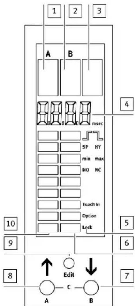
1 Display segment switching output Out A
2 Display segment switching output Out B (except OVEM-...-1PD)
3 Display segment switching input In A1 (except OVEM-...-1PD)
4 4-digit alphanumeric display
5 Toolbar for functions
6 Segment bar right: graphic display of the current status of the digital inputs or valve status
7 B pushbutton
8 A pushbutton
9 EDIT button
10 Segment bar left: graphic display of the current pressure value related to the maximum measured value of the measuring range
Fig. 2 LCD display and operating keys
| Symbol Description | |
| Threshold value comparator selected | |
| "[SP]" Switching point | |
| J | Window comparator selected |
| "[SP]" + "[min]" lower switching point | switching point |
| "[SP]" + "[max]" upper switching point | switching point |
| "[HY]" Hysteresis | |
| "[NO]/"[NC]" Switching | logic N/O contact (normally open) / N/C contact (normally closed) |
| "[TeachIn]" Teach function (teach-in) active | |
| "[Option]" Air saving function active | |
| "[Lock]" Security code active | |
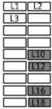 | Segments display the following:– current status of the digital inputs– current valve status→ Tab. 5 OVEM-...-2P/-2N/PU/PI: additional displays of segment bars – examples and→ Tab. 6 OVEM-...-1PD: additional displays of segment bars – examples |
Tab. 4 Symbols in display
| Display | Description | |
| Segment L10 is lit Vacuum solenoid valve is switched. | ||
| Segment L14 is lit Ejector pulse solenoid valve is switched. | ||
| Segment L17 + "[A]" lit and "[min]" flashing | Minimum pressure value display | |
| Segment L17 + "[A]" lit and "[max]" flashing | Maximum pressure value display | |
| Segment L18 + "[B]" lit and "[msec]" + "[_|~]l_" flashing | Duration of ejector pulse | |
| Segments L1, L3, L4, L5 lit and Diagnostics of evacuation and pressurisation times | ||
| "[msec]" + "[_|~]" + "[min]" flashing Display of minimum evacuation time | ||
| "[msec]" + "[_|~]" + "[max]" flashing Display of maximum evacuation time | ||
| "[msec]" + "[_|~]" + "[min]" flashing Display of minimum pressurisation time | ||
| "[msec]" + "[_|~]" + "[max]" flashing Display of maximum pressurisation time | ||
| "[msec]" + "[_|~]" + "[SP]" + "[max]" flashing | Display/setting of evacuation time critical limit value | |
| "[msec]" + "[_|~]" + "[SP]" + "[max]" flashing | Display/setting of pressurisation time critical limit value | |
| Segments L1, L2, L5, L6 lit and display " "- "[Option]" flashing | Setting of air saving function (EDIT mode)"": air saving function active": air saving function not active | |
| Segments L1, L2, L5, L6 lit and "[Lock]" flashing | Setting the security code (1...9999): security code is not active | |
| Segment L10 + "[B]" lit + display " " additional function of the electrical manual override via operating buttonsVacuum solenoid valve switched | ||
| Segment L14 + "[B]" lit + display " " additional function of the electrical manual override via operating buttonsEjector pulse solenoid valve (Eject) switched | ||
| Display Description | ||
| Segment L10 is lit Vacuum solenoid valve is switched. | ||
| Valve is switched. | ||
| Valve is switched. | ||
| Valve is switched. | ||
| Valve is switched. | ||
| Valve is switched. | ||
| Valve is switched. | ||
| Valve is switched. | ||
| Valve is switched. | ||
| Valve is switched. | ||
| Valve is switched. | ||
| Valv | ||
| Segments L1, L2, L5, L6 lit and display " - "[Option]" flashing | Setting of air saving function (EDIT mode)"": air saving function active": air saving function not active | |
| Segments L1, L2, L5, L6 lit and "[Lock]" flashing | Setting the security code (1...9999): security code is not active | |
| Segment L10 + "[B]" lit + display " " | additional function of the electrical manual override via operating buttons. Vacuum solenoid valve switched | |
| Segment L12 + "[B]" lit + display " " | additional function of the electrical manual override via operating buttons. Ejector pulse solenoid valve (Eject) switched | |
Tab. 5 OVEM-...-2P/-2N/PU/PI: additional displays of segment bars – examples
Tab. 6 OVEM-...-1PD: additional displays of segment bars – examples
5.2 Function
Function overview
The OVEM is a vacuum generator with digital transmission of setpoint and actual value as well as diagnostics and parameterisation options. It is configured with the operating keys. Diagnostic messages are shown on the display.
| Function OVEM-... | -2P/2N/P-U/PI | OVEM-...-1PD |
| Control of the compressed air supply with 2 valve functions→5.2.2 Valve control | x | x |
| Air saving function→5.2.3 Air saving function x x | ||
| Electrical and mechanical manual override→9.12 Electrical manual override and→9.11 Mechanical manual override | x | x |
| Monitoring of the vacuum build-up by integrated pressure sensor and advanced monitoring functions→5.2.5 Monitoring and diagnostics | x | x |
| Auto-drop function:Generation of an automatic ejector pulse/power ejector pulse for accelerated vacuum purging and safe set-down→5.2.2 Valve control | x | - |
| Generation of an ejector pulse/power ejector pulse via a control signal at the digital switching input (Eject) DI2 | - | x |
Tab. 7 Function overview
5.2.1 Switching functions
The solenoid valve for vacuum generation switches as an N/C or N/O contact, depending on the version, when pressurised with compressed air.
The switching outputs can be configured via the switching functions. The switching mode of the switching outputs can be set as threshold value or window comparators.
| Threshold value comparator Normally open (N/O contact) Normally closed (N/C contact) | ||
| Switching function:– 1 switching point (SP1)TEACH mode1):– 2 teach points (TP1, TP2)– SP1 = 1/2 (TP1+TP2) | 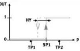 | 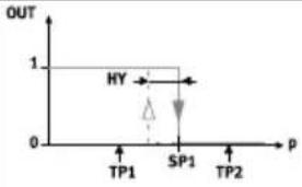 |
1) TP1 = minimum pressure value, TP2 = maximum pressure value, independent of the teach-in sequence Tab. 8 Threshold value comparator: setting of switching point SP1 and hysteresis HY
| Window comparator Normally open (N/O contact) Normally closed (N/C contact) | ||
| Switching function:– 2 switching points (SP1, SP2)TEACH mode1):– 2 teach points (TP1, TP2) | 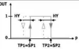 | 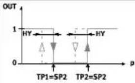 |
1) TP1 = minimum pressure value, TP2 = maximum pressure value, independent of the teach-in sequence Tab. 9 Window comparator: setting of switching points SP1, SP2 and hysteresis HY
| Code Switching output A Switching output B Switching inputs | |||
| -1PD Switching output positive switching pressure sensor output A | -2 switching inputs, positive | switching | |
| -2P Switching output positive switching pressure sensor output A | Switching output positive switching pressure sensor output B or diagnostic message channel | Switching input positive switching | |
| -2N Switching output negativeswitching pressure sensoroutput A | Switching output negativeswitching pressure sensoroutput B or diagnostic mes-sage channel | Switching input negativeswitching | |
| -PI Switching output positiveswitching pressure sensoroutput A | Analogue output 4 ... 20 mAvacuum | Switching input positiveswitching | |
| -PU Switching output positiveswitching pressure sensoroutput A | Analogue output 0 ... 10 Vvacuum | Switching input positiveswitching | |
Tab. 10 Switching output and switching input variants
5.2.2 Valve control
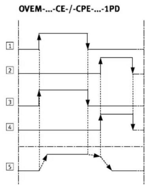
Control of the ejector pulse
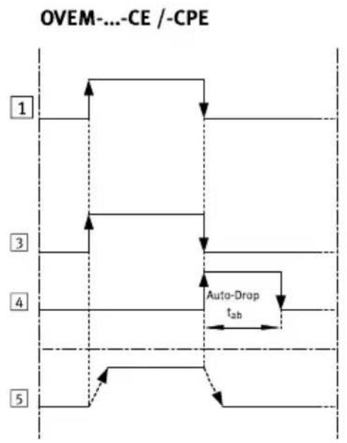
- Auto-drop function (except for OVEM-...-1PD)
The ejector pulse is generated after the “Suction” signal change.
The duration of the ejector pulse can be set→ 9.1 Setting the ejector pulse duration.
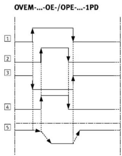
- Signal-controlled ejector pulse/power ejector pulse (OVEM-...-1PD only)
The ejector pulse is generated via a control signal at the digital switching input (ejection) DI2. The duration of the ejector pulse can be set via the duration of the control signal at the digital switching input (ejector) DI2. The vacuum solenoid valve or the ejector pulse solenoid valve is controlled as defined by the input signal.
i
Destruction of the vacuum sensor due to overpressure (-CPE/-OPE)
The exhaust duct is sealed tightly during the power ejector pulse. This can cause overpressure at the vacuum port and destroy the vacuum sensor.
- Use power ejector pulse only in open vacuum systems.
Product overview
flowchart
graph TD
    A["1"] --> B["Step 1"]
    B --> C["Step 2"]
    C --> D["Step 3"]
    D --> E["Step 4"]
    E --> F["Step 5"]
    F --> G["Auto-Drop t_ab"]
    style A fill:#f9f,stroke:#333
    style G fill:#bbf,stroke:#333
line
| Step | Value | | ---- | ----- | | 1 | ↑ | | 2 | ↑ | | 3 | ↑ | | 4 | ↑ | | 5 | ↓ |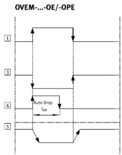
flowchart
graph TD
    A["1"] --> B["2"]
    B --> C["3"]
    C --> D["4"]
    D --> E["5"]
    E --> F["Auto-Drop t_ab"]
    style A fill:#f9f,stroke:#333
    style B fill:#f9f,stroke:#333
    style C fill:#f9f,stroke:#333
    style D fill:#f9f,stroke:#333
    style E fill:#f9f,stroke:#333
    style F fill:#f9f,stroke:#333
flowchart
graph TD
    A["1"] --> B["2"]
    B --> C["3"]
    C --> D["4"]
    D --> E["5"]
    style A fill:#f9f,stroke:#333
    style B fill:#f9f,stroke:#333
    style C fill:#f9f,stroke:#333
    style D fill:#f9f,stroke:#333
    style E fill:#f9f,stroke:#333
1 Control signal at the digital switching input (suction) DI1
2 Control signal at the digital switching input (ejection) DI2 (only OVEM-...-1PD)
3 Switching position of vacuum solenoid valve
4 Switching position of ejector pulse solenoid valve
5 Vacuum port (2)
tab Duration of ejector pulse
Fig. 3 Valve control switching characteristics
5.2.3 Air saving function
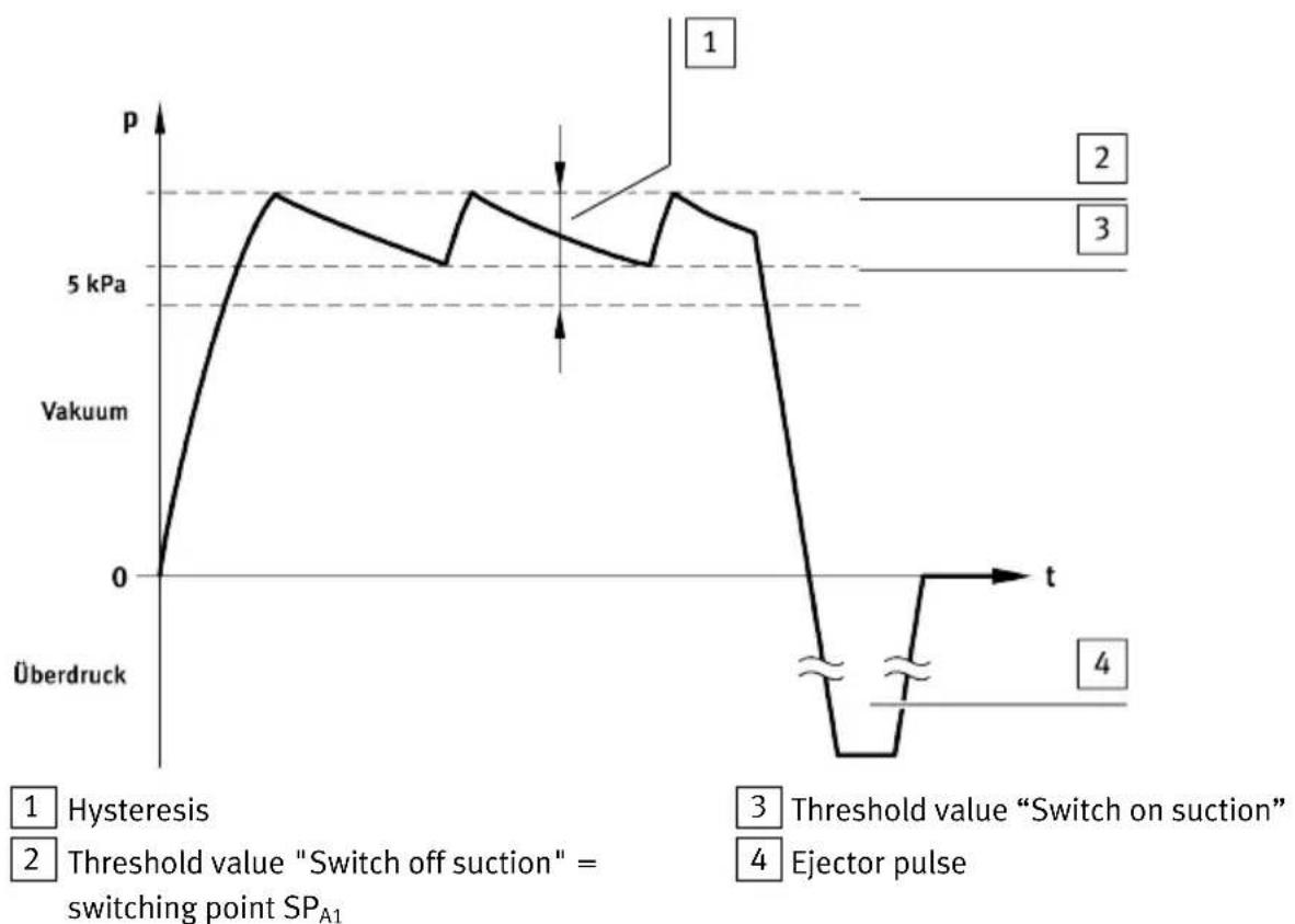
The air saving function reduces air consumption during the evacuation phase.
Product overview
line
| Event | Description | |-------|-------------| | 1 | Hysteresis | | 2 | Threshold value "Switch off suction" = switching point SP_A1 | | 3 | Threshold value "Switch on suction" | | 4 | Ejector pulse |Fig. 4 Mode of operation of the air saving function
If the pressure value has reached switching point SP1 2, vacuum generation is deactivated. An internal check valve prevents reduction of the vacuum. Vacuum can still be reduced slowly due to leakage in the overall system (e.g. due to rough workpiece surfaces). To reduce power consumption, vacuum generation is not switched on until it falls below the lower threshold value 3.
The air saving function is activated in the factory.
If air-permeable workpieces are transported, the vacuum is reduced more quickly, which would cause the vacuum generation to switch unnecessarily often. In this case, it makes sense to deactivate the air saving function 9.14 Switching air saving function on or off.
5.2.4 Optimisation of the transport time
The transport time can be optimised for variants with 2 switching outputs (OVEM-...-2P/-2N/-PU/-PI) by using switching output Out B.
The vacuum required for the transport is controlled by switching output Out A. To optimise the transport time, the workpiece can e.g. be gripped by the usable vacuum while the vacuum is building up.
The minimum usable vacuum required is monitored by switching output Out B.
5.2.5 Monitoring and diagnostics
The vacuum generator has monitoring functions that enable early detection of malfunctions or faults during operation.
- Monitoring of process parameters (pressure value at the vacuum connection, switching points, switching outputs and switching inputs, evacuation time t_E , pressurisation time t_B and critical limit values)
– Diagnostic messages → 11.1 Diagnostic levels
Product overview
– Fault detection → 11 Fault clearance
The diagnostic messages are shown on the display.
Switching output Out B can also be set as a diagnostic message channel (dl 1 or dl 2) for variants with 2 switching outputs (OVEM-...-2P/-2N)→ 9.4 Set diagnostic message channel.
The monitoring functions are activated at the factory (except for monitoring of the evacuation and pressurisation times). The time monitoring can be activated through setting of the critical limits for evacuation time and pressurisation
time→ 9.7 Setting critical limits for the evacuation and air supply times.
5.2.6 Measured variables
Pressure value (vacuum)
The pressure value (vacuum) between the vacuum port and filter is continuously measured.
i
In the OVEM-...-20/30-C, the pressure value (vacuum) between the filter and the check valve is continuously monitored.
The minimum and maximum measured pressure values are saved. If the operating voltage of the vacuum generator is switched off, these values are reset.
Cycle time
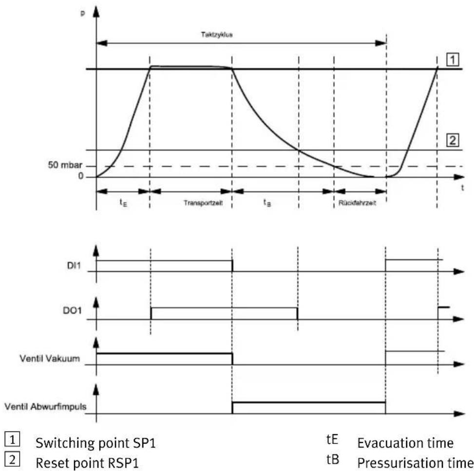
A cycle covers the time from the start of evacuation through ejection to the start of the new evacuation.
Evacuation time and pressurisation time
The evacuation time t_E is measured from the start of evacuation until switching point SP1 of the switching output is reached.
The pressurisation time t_B is measured from the start of pressurisation up to the time at which the pressure value (vacuum) falls below -50 mbar.
Product overview
line
| Time Segment | Signal | |----------------------|-----------------| | tE | 50 mbar | | tE / Transportzelt | 50 mbar | | tB | 50 mbar | | tB / Rückfahrzeit | 50 mbar | | Di1 | 50 mbar | | Do1 | 50 mbar | | Ventil Vakuum | 50 mbar | | Ventil Abwurfimpuls | 50 mbar |Fig. 5 Cycle time - example for Out A (air save)
The displayed sequence of the switching statuses and control signals applies to all product variants except OVEM-...-1PD. Sequence for OVEM-...-1PD Fig.3
5.2.7 Teach function
The Teach function enables configuration of the switching points and time monitoring during runtime.
Static teach-in
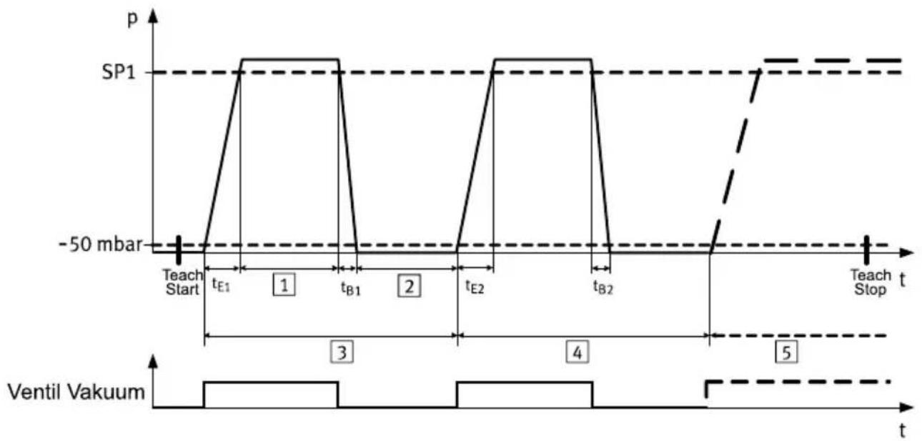
Depending on the Teach command, one switching point (SP) or 2 switching points (SP1, SP2) are determined from 2 teach points. The switching points are determined statically, that is, the measurement value remains constant during the entire teach-in procedure. The air saving function is deactivated during execution of the teach-in procedure.
Dynamic teach-in
Setpoint values are calculated within the teach-in procedure from a time period. The procedure is used to determine evacuation and air supply times. Fig.6
After the start of the teach-in, time t_E and t_B are measured at every cycle. The times are averaged over multiple cycle times. At the end of the teach-in, a function reserve of 100% is added to the averaged values.
Product overview
line
| Time Segment | Pulse Position | Annotation | | ------------ | -------------- | ------------------ | | Start | -50 mbar | -50 mbar | | Peak 1 | SP1 | SP1 | | Peak 2 | -50 mbar | -50 mbar | | Peak 3 | -50 mbar | -50 mbar | | Peak 4 | SP1 | SP1 | | Peak 5 | -50 mbar | -50 mbar |1 Transport time
4 Cycle time 2
2 Return time
5 Cycle time N
3 Cycle time 1
Fig. 6 Mode of operation of dynamic teach-in - example OVEM-...-CE/-CPE
5.2.8 Operating statuses and menu structure
Meaning of symbols for representing the menu structure
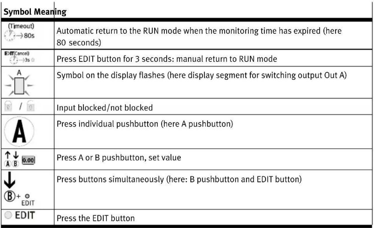 | |
| Symbol Meaning | |
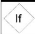 | Branching |
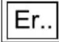 | Error display |
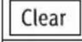 | Reset values |
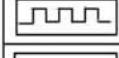 | Cycle |
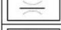 | Vacuum solenoid valve switched |
 | Ejector pulse solenoid valve switched |
 | Teach point is accepted |
 | Special menu (SPEC) is active (setting air saving function, security code, max. evacuation and max. air supply time) |
Tab. 11 Meaning of symbols for representing the menu structure
RUN mode
– Basic status after the operating voltage is applied
- Display of the current measured value (relative pressure)
– Display of the signal statuses of the solenoid valves
– Display of the selected inputs and outputs
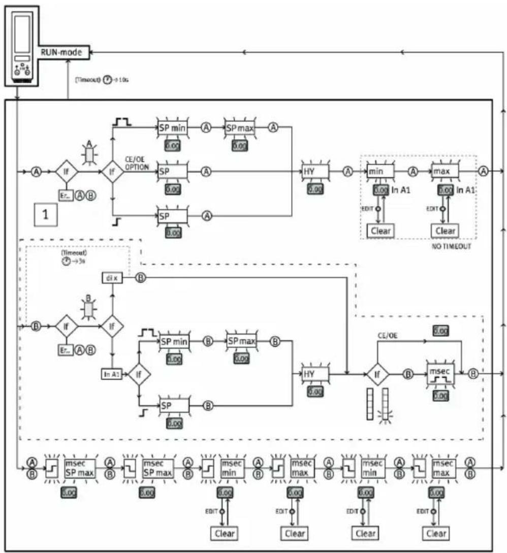
SHOW mode
- Display of the current settings
– Display and delete minimum and maximum pressure values - Display and delete minimum and maximum evacuation and pressurisation time
- Display of diagnostic messages
flowchart
graph TD
    A["RUN-mode"] --> B{CE/OE OPTION}
    B -->|Yes| C["SP min 0.00"]
    B -->|No| D["SP max 0.00"]
    C --> E["HY 0.00"]
    D --> E
    E --> F["min 0.00 In A1"]
    F --> G["Max 0.00 In A1"]
    G --> H["A"]
    G --> I["Clear"]
    H --> J["Clear"]
    J --> K["Clear"]
    L["Timeout"] --> M{CE/OE Options}
    M -->|Yes| N["SP min 0.00"]
    M -->|No| O["SP max 0.00"]
    N --> P["HY 0.00"]
    O --> P
    P --> Q["CE/OE"]
    Q --> R["msec min 0.00"]
    R --> S["msec max 0.00"]
    S --> T["Clear"]
    T --> U["Clear"]
    V["Timeout"] --> W{CE/OE Options}
    W -->|Yes| X["SP min 0.00"]
    W -->|No| Y["SP max 0.00"]
    Y --> Z["HY 0.00"]
    Z --> AA["msec min 0.00"]
    AA --> AB["msec max 0.00"]
    AB --> AC["Clear"]
    AC --> AD["Clear"]
    AE["NO TIMEOUT"] --> AF["Clear"]
    AG["Start"] --> AH["End"]
1 Submenu only available with
OVEM-...-2P/-2N/-PU/-PI
Fig. 7 Menu structure for SHOW mode
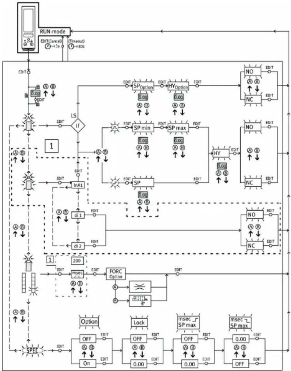
EDIT mode
- Setting of parameters
- Operation of the electrical manual override (FORC)
flowchart
graph TD
    A["RUN-mode"] --> B["EDIT(Cancel)"]
    B --> C{IS}
    C -->|A B| D["EDIT"]
    C -->|B| E["EDIT"]
    D --> F["SP Option"]
    F --> G["EDIT"]
    G --> H["HY Option"]
    H --> I["EDIT"]
    I --> J["NO"]
    J --> K["EDIT"]
    K --> L["NC"]
    L --> M["EDIT"]
    M --> N["SP min"]
    N --> O["EDIT"]
    O --> P["SP max"]
    P --> Q["EDIT"]
    Q --> R["HY"]
    R --> S["EDIT"]
    S --> T["NO"]
    T --> U["EDIT"]
    U --> V["SP min"]
    V --> W["EDIT"]
    W --> X["SP max"]
    X --> Y["EDIT"]
    Y --> Z["NO"]
    Z --> AA["EDIT"]
    AA --> AB["SP min"]
    AB --> AC["EDIT"]
    AC --> AD["SP max"]
    AD --> AE["EDIT"]
    AE --> AF["NO"]
    AF --> AG["EDIT"]
    AG --> AH["SP min"]
    AH --> AI["EDIT"]
    AI --> AJ["SP max"]
    AJ --> AK["EDIT"]
    AK --> AL["NO"]
    AL --> AM["EDIT"]
    AM --> AN["SP min"]
    AN --> AO["EDIT"]
    AO --> AP["SP max"]
    AP --> AQ["EDIT"]
    AQ --> AR["NO"]
    AR --> AS["EDIT"]
    AS --> AT["SP min"]
    AT --> AU["EDIT"]
    AU --> AV["SP max"]
    AV --> AW["EDIT"]
    AW --> AX["NO"]
    AX --> AY["EDIT"]
    AY --> AZ["SP min"]
    AZ --> BA["EDIT"]
    BA --> BB["SP max"]
    BB --> BC["EDIT"]
    BC --> BD["NO"]
    BD --> BE["EDIT"]
    BE --> BF["SP min"]
    BF --> BG["EDIT"]
    BG --> BH["SP max"]
    BH --> BI["EDIT"]
    BI --> BJ["NO"]
    BJ --> BK["EDIT"]
    BK --> BL["SP min"]
    BL --> BM["EDIT"]
    BM --> BN["SP max"]
    BN --> BO["EDIT"]
    BO --> BP["NO"]
    BP --> BQ["EDIT"]
    BQ --> BR["SP min"]
    BR --> BS["EDIT"]
    BS --> BT["SP max"]
    BT --> BU["EDIT"]
    BU --> BV["NO"]
    BV --> BW["EDIT"]
    BW --> BX["SP min"]
    BX --> BY["EDIT"]
    BY --> BZ["SP max"]
    BZ --> CA["EDIT"]
    CA --> CB["NO"]
    CB --> CC["EDIT"]
    CC --> CD["SP min"]
    CD --> CE["EDIT"]
    CE --> CF["SP max"]
    CF --> CG["EDIT"]
    CG --> CH["NO"]
    CH --> CI["EDIT"]
    CI --> CJ["SP min"]
    CJ --> CK["EDIT"]
    CK --> CL["SP max"]
    CL --> CM["EDIT"]
1 Submenu only available with OVEM-...-CE/-OE/-CPE/-OPE
Fig. 8 EDIT mode menu structure
Assembly
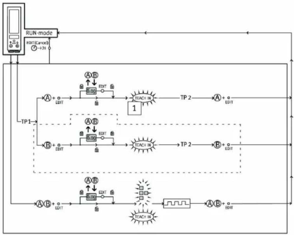
TEACH mode
- Acceptance of the current measured value to determine switching points
flowchart
graph TD
    A["RUN-mode"] --> B["EDIT(Cancel)"]
    B --> C["→3s"]
    C --> D["TP1"]
    D --> E["A + EDIT"]
    E --> F["0.00 EDIT"]
    F --> G["TEACH IN 1"]
    G --> H["TP 2"]
    H --> I["A + EDIT"]
    I --> J["TP 2"]
    J --> K["B + EDIT"]
    K --> L["TEACH IN"]
    L --> M["0.00 EDIT"]
    M --> N["TEACH IN"]
    N --> O["0.00 EDIT"]
    O --> P["TEACH IN"]
    P --> Q["0.00 EDIT"]
    Q --> R["TEACH IN"]
    R --> S["0.00 EDIT"]
    S --> T["TEACH IN"]
    T --> U["0.00 EDIT"]
    U --> V["TEACH IN"]
    V --> W["0.00 EDIT"]
    W --> X["TEACH IN"]
    X --> Y["0.00 EDIT"]
    Y --> Z["TEACH IN"]
    Z --> AA["0.00 EDIT"]
    AA --> AB["TEACH IN"]
    AB --> AC["0.00 EDIT"]
    AC --> AD["TEACH IN"]
    AD --> AE["0.00 EDIT"]
    AE --> AF["TEACH IN"]
    AF --> AG["0.00 EDIT"]
    AG --> AH["TEACH IN"]
    AH --> AI["0.00 EDIT"]
    AI --> AJ["TEACH IN"]
    AJ --> AK["0.00 EDIT"]
    AK --> AL["TEACH IN"]
    AL --> AM["0.00 EDIT"]
    AM --> AN["TEACH IN"]
    AN --> AO["0.00 EDIT"]
    AO --> AP["TEACH IN"]
    AP --> AQ["0.00 EDIT"]
    AQ --> AR["TEACH IN"]
    AR --> AS["0.00 EDIT"]
    AS --> AT["TEACH IN"]
    AT --> AU["0.00 EDIT"]
    AU --> AV["TEACH IN"]
    AV --> AW["0.00 EDIT"]
    AW --> AX["TEACH IN"]
    AX --> AY["0.00 EDIT"]
    AY --> AZ["TEACH IN"]
    AZ --> BA["0.00 EDIT"]
    BA --> BB["TEACH IN"]
    BB --> BC["0.00 EDIT"]
    BC --> BD["TEACH IN"]
    BD --> BE["0.00 EDIT"]
    BE --> BF["TEACH IN"]
    BF --> BG["0.00 EDIT"]
    BG --> BH["TEACH IN"]
    BH --> BI["0.00 EDIT"]
    BI --> BJ["TEACH IN"]
    BJ --> BK["0.00 EDIT"]
    BK --> BL["TEACH IN"]
    BL --> BM["0.00 EDIT"]
    BM --> BN["TEACH IN"]
1 Submenu only available with OVEM-...-2P/-2N
Fig. 9 TEACH mode menu structure
6 Assembly
i
An unfavourable mounting position may impair the function of the product.
- Avoid condensate accumulation in the device through a suitable mounting position.
- Exhaust air must be able to flow out unhindered.
Assembly
Direct mounting
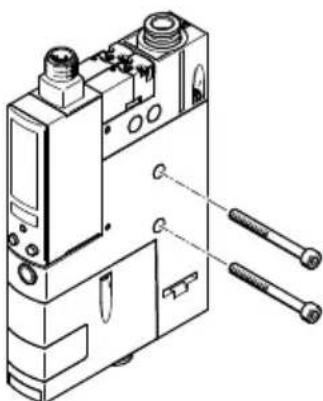
Fig. 10 Direct mounting on the side
| Variant Screws Tightening torque | ||
| OVEM-...-05/-07/-10-...-B/-BN M5 max. 2.5 Nm | ||
| OVEM-...-14/-20-...-B/-BN M4 max. 2.5 Nm | ||
| OVEM-...-20/-30-...-C M6 max. 2.5 Nm |
Tab. 12 Size and tightening torque of the screws for direct mounting on the side
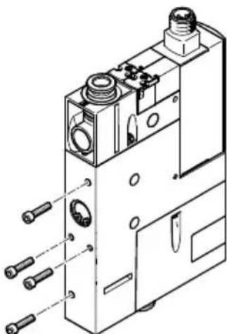
natural_image
Technical line drawing of a mechanical component with multiple ports and mounting holes (no text or symbols)Fig. 11 Direct mounting on the back
| Variant Screw Tightening torque | ||
| OVEM-...-05/-07/-10/-14/-20-...-B/-BN M3 max. 0.8 Nm | ||
| OVEM-...-20/-30-...-C M4 max. 0.8 Nm |
Tab. 13 Size and tightening torque of the screws with direct mounting on the back
H-rail mounting
i
Type of mounting permissible only for sizes OVEM-...-05/-07/-10/-14/-20-...-B/-BN
H-rail mounting accessories → www.festo.com/catalogue
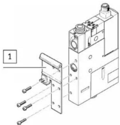
1 H-rail mounting
natural_image
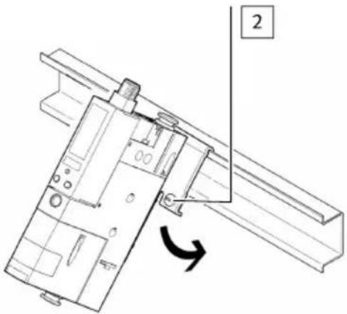
Technical line drawing of a mechanical assembly with no visible text or symbols2 Screw
Fig. 12 H-rail mounting
- Attach mounting plate on H-rail mounting 1.
- Attach OVEM with H-rail mounting to the H-rail and press in the direction of the arrow.
- Secure to the H-rail with screw 2.
Mounting with mounting bracket
i
Type of mounting permissible only for sizes OVEM-...-05/-07/-10/-14/-20-...-B/-BN
Accessories for mounting bracket → www.festo.com/catalogue

natural_image
Technical line drawing of a mechanical device with mounting holes and two separate parts (no text or symbols)Fig. 13 Mounting with mounting bracket
| Variant Screws Tightening torque | ||
| OVEM-...-05/-07/-10-...-B/-BN M5 max. 2.5 Nm | ||
| OVEM-...-14/-20-...-B/-BN M4 max. 2.5 Nm |
Tab. 14 Size and tightening torque of the screws for mounting with mounting bracket
Mounting on common supply manifold
OVEM-...-B/-BN: Mounting is possible on a common supply manifold with a maximum of 8 places.
OVEM-...-C: Mounting is possible on a common supply manifold with a maximum of 4 places.
Assembly instructions for common supply manifold OABM-P → www.festo.com/sp
7 Installation
7.1 Pneumatic installation
| Variant Circuit symbol Variant Circuit symbol | |||
| OVEM-...-QO-CNOVEM-...-GO-CN | 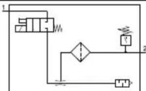 | OVEM-...-QO-CEOVEM-...-GO-CE | 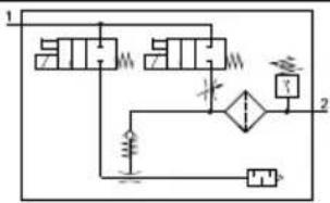 |
| OVEM -...- QO-CPEOVEM -...- GO-CPE | 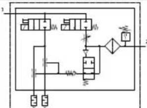 | OVEM -...- QO-CPEOVEM -...- GO-CPE | 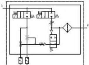 |
| OVEM-...-QS-CNOVEM-...-GN-CN | 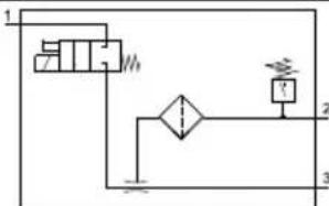 | OVEM-...-QS-CEOVEM-...-GN-CE | 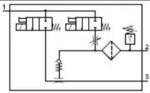 |
| OVEM -...- QS-CPEOVEM -...- GN-CPE | 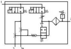 | OVEM -...- QS-CPEOVEM -...- GN-CPE | 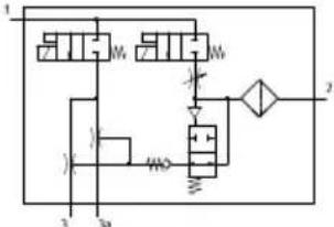 |
| OVEM-...-QO-ONOVEM-...-GO-ON | 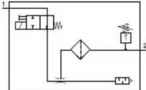 | OVEM-...-QO-OEOVEM-...-GO-OE | 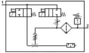 |
| OVEM -...- QO-OPEOVEM -...- GO-OPE | 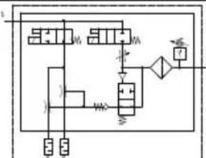 | OVEM -...- QO-OPEOVEM -...- GO-OPE | 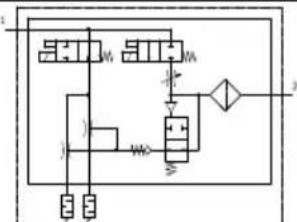 |
| OVEM-...-QS-ONOVEM-...-GN-ON | 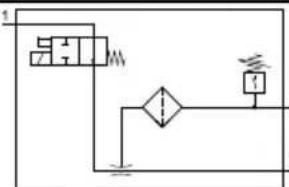 | OVEM-...-QS-OEOVEM-...-GN-OE | 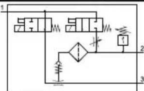 |
| OVEM -...- QS-OPEOVEM -...- GN-OPE | 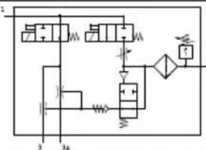 | OVEM -...- QS-OPEOVEM -...- GN-OPE | 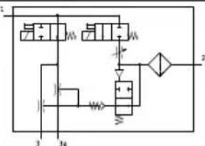 |
Tab. 15 Circuit symbols, pneumatic
| OVEM-... -05-... | GN -07-...-GN | -10-...-GN -14 | ...-GN -20-...-GN | -30-...-GN | ||||||||
| -05-...-GO -07 | ...-GO -10-...-GO | -14-...-GO | -20-...-GO -30-...-GO | |||||||||
| Tube length [m] | <0.5 | <2 | <0.5 | <2 | <0.5 | <2 | <0.5 | <2 | <0.5 | <2 | <0.5 | <2 |
| Min. internal diameter of tubing [mm] | ||||||||||||
| - Supply port 1 2 | 1.5 2 2 | 3 3 4 4 | 5 6 7 | |||||||||
| - Vacuum port 2 | 3 3 4 4 | 5 5.5 6 | 6 7 9 1 | 1 | ||||||||
| - Exhaust port 2 | 3 3 4 4 | 5 5.5 6 | 6 7 9 1 | 1 | ||||||||
Tab. 16 Minimum inside diameter of the connection tubes for connections with G-female thread
Notes on the pneumatic connection
- Maximum permissible tube length 2 m
- OVEM-...-GN/-GO: minimum inside diameter of the connection tubes
→ Tab. 16 Minimum inside diameter of the connection tubes for connections with G-female thread.
- Do not seal exhaust port.
- OVEM-...-07/-10/-14/-20/-30: If necessary, lengthen silencers with a silencer extension
→ www.festo.com/catalogue.
- Recommendation: Use type PUN tubes www.festo.com/catalogue.
7.2 Electrical installation
WARNING!
Risk of injury due to electric shock.
- For the electrical power supply, use only PELV circuits in accordance with IEC 60204-1/EN 60204-1 (Protective Extra-Low Voltage, PELV).
- Observe the general requirements of IEC 60204-1/EN60204-1 for PELV circuits.
- Only use voltage sources that ensure a reliable electric separation from the mains network in accordance with IEC 60204-1/EN 60204-1.
- Connect the vacuum generator to the electrical connection.
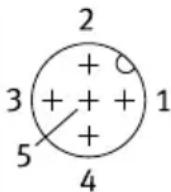
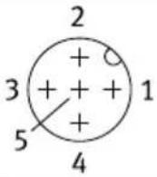
- 5-pin plug, M12x1
– Maximum tightening torque of M12 plug: 0.5 Nm
– Maximum permissible cable length: 20 m
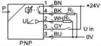
| Plug Pin Wire colour | 1) | Function | ||
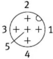 | 1 brown | (BN) L+ +24 V | ||
| 2 white | (WH) DO2 digital | output | Out B | |
| 3 blue | (BU) L- 0 V | |||
| 4 black | (BK) DO1 digital | output | Out A/Out A (air-save) | |
| 5 grey | (GY) DI1 Digital switching | input | (suction) 2) | |
1) When using the connecting cable as per Accessories
2) The workpiece is set down with a falling edge of the "Suction" control signal.
Tab. 17 Pin allocation OVEM-...-2P/-2N
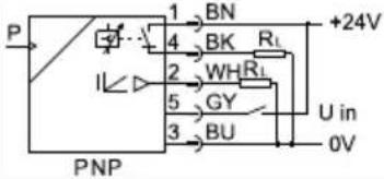
| Plug Pin Wire colour | 1) | Function | ||
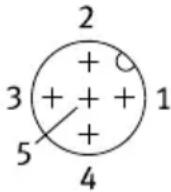 | 1 brown | (BN) L+ +24 V | ||
| 2 white | (WH) AO1 Analogue output Out B | |||
| 3 blue | (BU) L- 0 V | |||
| 4 black | (BK) DO1 digital output Out A/Out A (air-save) | |||
| 5 grey | (GY) DI1 Digital switching input (suction) | 2) | ||
1) When using the connecting cable as per Accessories
2) The workpiece is set down with a falling edge of the "Suction" control signal.
Tab. 18 Pin allocation OVEM ... PU/PI
| Plug Pin Wire colour | 1) | Function | ||
 | 1 brown | (BN) L+ +24 V | ||
| 2 white | (WH) DO1 digital | output | Out A/Out A (air-save) (PNP) | |
| 3 blue | (BU) L- 0 V | |||
| 4 black | (BK) DI2 digital s | witching | input (ejection) (PNP) | |
 | 5 grey (GY) DI1 digital switching input (suction) (PNP) | |||
1) When using the connecting cable as per Accessories
Tab. 19 Pin allocation OVEM-...-1PD
Circuit Diagrams
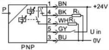
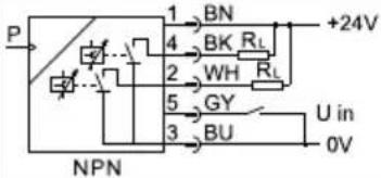
| OVEM-...-2P OVEM-...-2N | |||
 |  | ||
| OVEM-...-PU OVEM-...-PI | |||
 |  | ||
| OVEM-...-1PD | |||
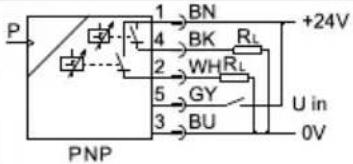 | |||
Tab. 20 Circuit diagrams for vacuum generator
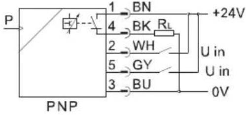
| Circuit Diagrams | |
| OVEM-...-1P OVEM-...-1N | |
 | 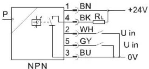 |
| OVEM without vacuum sensor | |
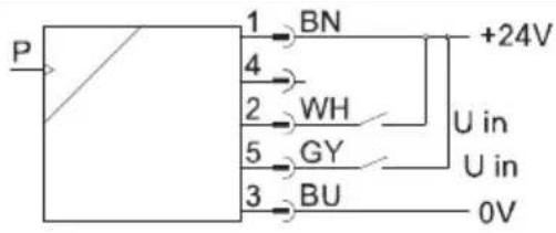 |
Tab. 21 Circuit diagrams for vacuum generator
8 Commissioning
i
Commissioning by qualified personnel.
8.1 Commissioning the vacuum generator
At initial commissioning, the vacuum generator is placed in operation with the factory settings
→ Tab. 22 Factory settings.
Requirement
Vacuum generator is fully mounted and connected 6 Assembly.
Checking operating conditions
- Check operating conditions and critical limits 14 Technical data.
Commissioning the vacuum generator OVEM-...-OE/-OPE
- Apply operating pressure to supply port (1).
Negative pressure is generated at the vacuum port (2).
- Switch on the operating voltage.
The current pressure is displayed and the vacuum generator is ready for operation.
Commissioning the vacuum generator OVEM-...-CE/-CPE
-
Apply operating pressure to supply port (1).
-
Switch on the operating voltage.
-
Activate suction: apply input signal to pin 5.
Negative pressure is generated at the vacuum port (2). The current pressure is displayed and the vacuum generator is ready for operation.
Changing the operating pressure changes the power of the negative pressure at the vacuum port. This allows the vacuum to be adjusted.
Functions and parameters can be specified:
- manually at the device EDIT mode
-by teach-in TEACH mode
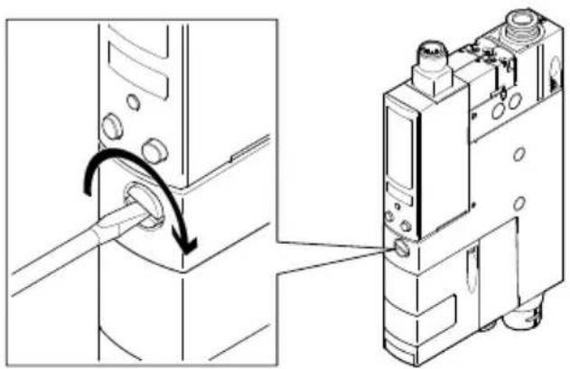
8.2 Setting the intensity of the ejector pulse
natural_image
Technical diagram showing a mechanical component being inserted into a device, with no visible text or symbols.Fig. 14 Set the intensity of the ejector pulse
Requirement
– Vacuum generator is in operation
Feed through with automatic ejector pulse (-2P/-2N/-NU/-NI/-PU/-PI)
- Screw in the flow control screw 10 completely
The channel for the ejector pulse is closed. An ejector pulse is not generated.
- Switch on vacuum generation.
Negative pressure is generated at the vacuum port.
-
Switch off vacuum generation.
-
Unscrew flow control screw slightly.
An automatic ejector pulse is generated. If an automatic ejector pulse is not generated, operate the mechanical manual override of the ejector pulse solenoid valve.
- Screw the flow control screw out or in to adjust the ejector pulse to the required intensity.
i
Setting the ejector pulse duration 9.1 Setting the ejector pulse duration
i
The use of large suction cups with connectors can create a device-independent vacuum due to the interference resistance when the suction cup with connector is detached from the workpiece.
Set up the ejector pulse accordingly.
Requirement
– Vacuum generator is in operation
Procedure without automatic ejector pulse (1PD)
-
Completely screw in flow control screw for regulation of the ejector pulse.
-
Switch on vacuum generation.
Negative pressure is generated at the vacuum port (2).
-
Switch off vacuum generation.
-
Switch on solenoid valve for ejector pulse.
An ejector pulse is not generated.
-
Switch off solenoid valve for ejector pulse.
-
Slightly unscrew the flow control screw to regulate the ejector pulse.
-
Switch on solenoid valve for ejector pulse.
An ejector pulse is generated.
- Repeat steps 1 to 7 until the required intensity of the ejector pulse is set.
i
The use of large suction cups with connectors can create a device-independent vacuum due to the interference resistance when the suction cup with connector is detached from the workpiece.
Set up the ejector pulse accordingly.
9 Operation and use
Additional information on operating statuses and menu structure
→ 5.2.8 Operating statuses and menu structure
9.1 Setting the ejector pulse duration
Requirements
- RUN mode is active.
– Security code is not active.
Processing
- Press the EDIT button.
[A] flashes and EDIT mode is active.
- Press B pushbutton.
[B] + segment L18 flash.
- Press the EDIT button.
[msec], [_l^-] and [^-l_] flash.
-
Set time (in ms) with the A button and the B button. To deactivate the ejector pulse, set to OFF.
-
Press and hold the EDIT button for 3 seconds.
RUN mode is active.
i
When large suction grippers are used, a vacuum independent of the device may be built up for physical reasons. The result is that the workpiece may not be released from the suction gripper, even if the ejector pulse is set to a sufficiently long duration.
9.2 Configuring switching outputs
Display settings of the switching outputs
i
The process for displaying the settings of the switching outputs Out A (A-pushbutton) and Out B (B-pushbutton) is basically identical. In addition, the configuration of the switching output and the duration of the ejector pulse is displayed for switching output Out B. The process is described below using switching output Out A as an example.
Requirement
- RUN mode is active.
Processing
- Press the A pushbutton.
SHOW mode is active. The error number is displayed in case of errors.
- Press the A pushbutton.
The following settings will be displayed:
- switching function (threshold value comparator or window comparator)
- Switching points [SP] or [SP][min].
– Switching characteristic [NO/NC]
- Press the A pushbutton.
Only with Window comparator switching function: switching point [SP], [max] is displayed.
- Press the A pushbutton.
– Hysteresis [HY] is displayed.
- Press the A pushbutton.
Minimum pressure value is displayed.
- Press the A pushbutton.
Maximum pressure value is displayed.
- Press the A pushbutton.
RUN mode is active.
9.3 Setting the switching characteristics of a switching output
i
The process for setting the switching outputs Out A (A-pushbutton) and Out B (B-pushbutton) is basically identical. The switching output Out B must also be defined as switching output In A1, because Out B can also be configured as a diagnostic message channel 9.4 Set diagnostic message channel. The process is described below using switching output Out A as an example.
Requirements
- RUN mode is active.
- Switching output Out B is defined as switching output In A1.
– Security code is not active.
Processing
- Press the EDIT button.
[A] flashes. EDIT mode is active.
- Press B pushbutton.
[B] flashes.
- Press the EDIT button.
Display
- Press the EDIT button.
The currently set switching function flashes (threshold value comparator or window comparator).
-
Set switching function using the A or B pushbutton.
-
Press the EDIT button.
[SP] flashes (threshold value comparator) or [SP], [min] flashes (window comparator).
-
Set switching point (SP or SPmin) with the A or B pushbutton.
-
Press the EDIT button.
Only with switching function window comparator: [SP], [max] flashes.
- Set switching point (SPmax) with the A or B pushbutton.
- Press the EDIT button.
→ [HY] flashes.
-
Set hysteresis [HY] with the A or B pushbutton.
-
Press the EDIT button.
[NO] or [NC] flashes.
-
Set the switching characteristic [NO/NC] with the A or B pushbutton.
-
Press the EDIT button.
RUN mode is active.
9.4 Set diagnostic message channel
i
If switching output Out B is set as diagnostic message channel (dl 1 or dl 2), switching output Out B can no longer be used as switching output In A1.
Requirements
- RUN mode is active.
– Security code is not active.
Processing
- Press the EDIT button.
[A] flashes. EDIT mode is active.
- Press B pushbutton.
[B] flashes.
- Press the EDIT button.
If Out B is defined as switching output,
- Set the diagnostic message channel (dl 1 or dl 2) using the A or B pushbutton.
Operation and use
- Press the EDIT button.
[NO] or [NC] flashes.
-
Set the switching characteristic [NO/NC] with the A or B pushbutton.
-
Press the EDIT button.
RUN mode is active.
9.5 Teach-in switching point
i
The air saving function is automatically deactivated during teach-in. If the pressure differential between the teach points is too low, teach-in will not work.
i
The process is the same for teach-in of switching outputs Out A (A pushbutton) and Out B (B pushbutton). The process is described below using switching output Out A as an example.
Requirements
- RUN mode is active.
- Switching function is set.
– Security code is not active.
Procedure
Object gripped or object not gripped – the sequence is freely selectable.
- Set the vacuum for the first teach point.
- Press the A pushbutton and the EDIT button simultaneously.
- TEACH mode is active.
– Air saving function is deactivated.
- Measured value will then be taken as first teach point (TP1).
– [A] and [TeachIn] flash.
- Set the vacuum for the second teach point (TP2).
- Press the A pushbutton and the EDIT button simultaneously.
- Measured value is taken as second teach point (TP2).
- Switching points (SP or SPmin and SPmax) are valid.
– Air saving function is activated. - RUN mode is active.
i
The hysteresis is adjusted to the teach-in values. Set hysteresis
(→ 9.2 Configuring switching outputs).
Recommendation: check the teach-in values in a test run.
9.6 Deleting minimum or maximum pressure value
Requirements
- RUN mode is active.
Processing
- Press the A pushbutton.
SHOW mode is active.
If there are errors, the error numbers are shown.
-
Repeatedly press the A pushbutton until the minimum pressure value is displayed.
-
Press the A pushbutton to see the next value.
Press the EDIT button to delete the minimum pressure value.
The minimum pressure value is deleted.
- Press the A pushbutton.
Maximum pressure value is displayed.
- Press the A pushbutton to return to RUN mode.
Press the EDIT button to delete the maximum pressure value.
The maximum pressure value is deleted.
- Press the A pushbutton.
RUN mode is active.
9.7 Setting critical limits for the evacuation and air supply times
Requirements
- EDIT mode is active and [Out A] flashes.
– Security code is not active.
Processing
- Press the A pushbutton.
Display
- Press the EDIT button.
[Option] flashes.
- Press the EDIT button.
[Lock] flashes.
- Press the EDIT button.
[msec] + [ ^- | _ ] + [SP] + [max] flash.
- Set the maximum evacuation time using the A pushbutton and B pushbutton.
[OFF]: evacuation time monitoring is not active.
- Press the EDIT button.
[msec] + [SP] + [max] and [^-|_-] flash.
- Set the maximum air supply time using the A pushbutton and B pushbutton.
[OFF]: air supply time monitoring is not active.
- Press the EDIT button.
RUN mode is active.
9.8 Teaching evacuation and air supply time
Requirements
- RUN mode is active.
– Security code is not active. - Switching function is set.
Processing
-
Press the A and B pushbuttons and EDIT button simultaneously.
-
TEACH mode is active.
– [TeachIn] and the diagnostics segments flash. -
Measure at least one clock cycle.
i
An average is calculated from the measured cycles.
The more cycles are run the better the value. The teach-in values are applied with a function reserve of 100%.
- Press the A pushbutton, B pushbutton and EDIT button.
RUN mode is active.
i
If the switching points or the intensity of the ejector pulse are changed, teach-in the evacuation and air supply times again.
Recommendation: check the teach-in values in a test run.
9.9 Displaying evacuation and air supply times
Requirement
- RUN mode is active.
Processing
-
Press A and B pushbuttons simultaneously.
-
SHOW mode is active.
– Evacuation time critical limit is displayed. -
Press A and B pushbuttons simultaneously.
Air supply critical limit is displayed.
- Press A and B pushbuttons simultaneously.
Minimum evacuation time is displayed.
- Press A and B pushbuttons simultaneously.
Maximum evacuation time is displayed.
- Press A and B pushbuttons simultaneously.
Minimum air supply time is displayed.
- Press A and B pushbuttons simultaneously.
Maximum air supply time is displayed.
- Press A and B pushbuttons simultaneously.
RUN mode is active.
9.10 Deleting evacuation and air supply times
Requirements
- SHOW mode is active.
– Minimum evacuation time is displayed.
Operation and use
Processing
-
Press the A and B pushbuttons simultaneously to display the next value. Press the EDIT button to delete the displayed value.
-
Press A and B pushbuttons simultaneously.
RUN mode is active.
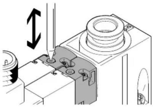
9.11 Mechanical manual override
Both solenoid valves can be manually switched with the manual override.
natural_image
Technical line drawing of a mechanical assembly with no visible text or symbolsFig. 15
- Press in the plunger of the manual override with a blunt pin.
The solenoid valve switches.
- Remove pin.
The plunger of the manual override is automatically reset. The solenoid valve returns to the initial position.
9.12 Electrical manual override
Requirements
- RUN mode is active.
– Security code is not active.
Procedure
- Press the EDIT button.
- [A] flashes. - EDIT mode is active.
- Press B pushbutton.
[B] flashes + segment L18 illuminated.
- Press the EDIT button.
[msec], [_l^-] and [^-l_] flash. The duration of the ejector pulse is displayed.
- Press the EDIT button.
◀
- Switch solenoid valves.
- Vacuum solenoid valve: press A pushbutton. - Ejector pulse solenoid valve: press B pushbutton.
Operation and use
- Press the EDIT button to exit the submenu.
RUN mode is active.
9.13 Activating the security code
A security code can be set and activated to prevent changes by unauthorised persons.
- Factory setting: "OFF"
- The security code is reset when factory settings are restored.
Requirements
- RUN mode is active.
– Security code is not active.
Procedure
- Press the EDIT button.
- [A] flashes. - EDIT mode is active.
- Press the A pushbutton.
Display
- Press the EDIT button.
[Option] flashes.
- Press the EDIT button.
[Lock] flashes.
- Set the security code with the A and B pushbuttons.
[OFF]: security code is not active.
- Press and hold the EDIT button for 3 seconds.
RUN mode is active.
9.14 Switching air saving function on or off
Requirements
- EDIT mode is active and [Out A] flashes.
– Security code is not active.
Processing
- Press the A pushbutton.
Display
- Press the EDIT button.
[Option] flashes.
- Switch the air saving function on or off using the A or B pushbutton.
– [ON]: air saving function active. – [OFF]: air-saving function not active.
- Press and hold the EDIT button for 3 seconds.
RUN mode is active.
9.15 Restore factory settings
Restoring the factory settings resets the parameters, configuration and security code to the delivery status. → Tab. 22 Factory settings
The current settings are lost.
- Switch off operating voltage.
- Press and hold the A-pushbutton + B-pushbutton + EDIT button.
- Switch on the operating voltage.
Display - Release A-pushbutton + B-pushbutton + EDIT button.
The factory settings are restored.
Factory settings
| Parameter OVEM-...-H OVEM-...-L | |||
| Switching mode of the electrical output Threshold value comparator | |||
| Switching logic of the electrical output NO (normally open) | |||
| Air saving function Active | |||
| Security code OFF | |||
| SP1 [bar] -0.7 -0.4Out A (air save) | |||
| Hysteresis [bar] 0.25 | |||
| Out A | SP1 [bar] -0.7 -0.4 | ||
| SP2 [bar] -0.97 -0.67 | |||
| Hysteresis [bar] 0.25 0.1 | |||
| Out B^1) | SP1 [bar] -0.5 -0.2 | ||
| SP2 [bar] -0.71 -0.41 | |||
| Hysteresis [bar] 0.2 0.1 | |||
| Duration of ejector pulse^1) | [ms] 200 | ||
1) parameter not available for OVEM-...-1PD
Tab. 22 Factory settings
10 Maintenance and care
Clean device
-
Switch off energy sources:
-
Operating voltage
-
Compressed air
-
Clean device with non-abrasive cleaning agents.
- Check air filter through the display window for dirt.
Replace air filter
i
The air filter cannot be replaced in the vacuum generator OVEM-...-20/-30-C
Fault clearance
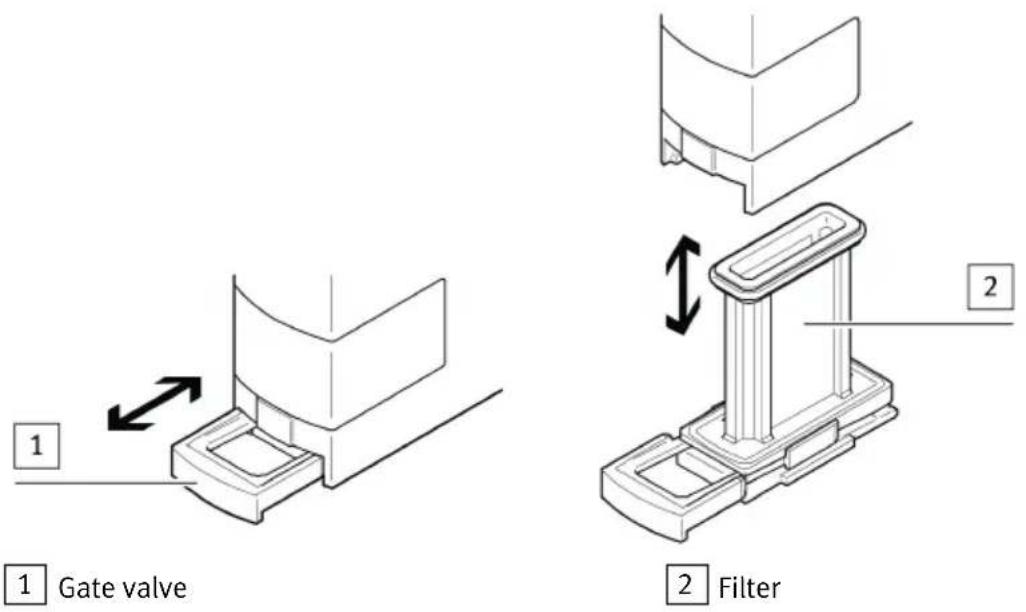
Fig. 16 Remove/install air filter
-
Exhaust the vacuum generator.
-
Carefully pull gate valve 1 out to the first detent. The gate valve must stay in this position on the filter.
-
Pull filter 2 out. Clean with white spirit.
-
Push filter into the housing.
-
Push in gate valve.
The gate valve pushes the filter into the vacuum generator.
11 Fault clearance
The diagnostic messages are shown as error code on the display. For variants with 2 switching outputs (OVEM-...-2P/-2N) one of the two logical channels of the switching output Out B can also be used as a diagnostic message channel 9.4 Set diagnostic message channel. The diagnostic message channel can be configured as a normally open (N/O contact) or a normally closed (N/C contact).
11.1 Diagnostic levels
There are 4 diagnostic levels. The backlight of the display shows red for messages of diagnostic levels 1 to 3.
| Diagnostic level | Diagnostic message channel Description |
| 0 no message Device is OK. | |
| 1 logical channel dl 1 is active no restriction in function yet but operating parameters are deteriorating | |
| Diagnostic level | Diagnostic message channel Description | |
| 2 logical channel | dl 1 or dl 2 is active | Function still ensured, but with restrictions (e.g. higher power consumption).Emergency operation, maintenance urgently required. |
| 3 logical channel | dl 1 or dl 2 is active | Function no longer ensured.All controllable outputs of the device are inactive. |
Tab. 23 Diagnostic levels for switching output Out B and display
If the evacuation and pressurisation time is to be monitored, set the critical limits for the evacuation and pressurisation time 9.14 Switching air saving function on or off.
11.2 Error messages and error codes
| Display Diagnostic level | Description Remedy | |
| Er01 3 Hardware errors in device – Replace device. | ||
| Er17 3 Supply voltage is too high or too low (error) | – Check supply voltage. | |
| Er20 2 permissible device temperature exceeded | – Keep device away from heat sources. | |
| Er21 2 Short-circuit | Out A – Check output for overload. | – Check installation. |
| Er32 2 OVEM-...-1PD: Vacuum solenoid valve does not switch or does not switch correctly | – Press mechanical manual override several times.– Check supply voltage.– Replace device. | |
| Er33 2 | except for OVEM-...-1PD: Solenoid valve does not switch or does not switch correctly.Plunger does not move; current through solenoid coil is too low; short circuit in solenoid coil | – Press mechanical manual override several times.– Check supply voltage.– Replace device. |
| OVEM-...-1PD: Ejector pulse solenoid valve does not switch or does not switch correctly | ||
Fault clearance
| Display Di- gnostic level | Description Remedy | |
| Er34 1 Evacuation time exceeded in 2 of 5 cycles | - Check for leakage. | |
| Er35 2 Evacuation time exceeded by a factor of two in 2 of 5 cycles | ||
| Er36 1 Air supply time exceeded in 2 of 5 cycles | - Check for leakage.- Extend air supply time.- Check throttle setting. | |
| Er37 2 Air supply time exceeded in 2 of 5 cycles | ||
| Er38 2 Switching frequency of air saving function >1 Hz (warning) | - Check for leakage. | |
| Er39 2 | SP1 for Out A not reached after 10 s - Check for leakage.- Check compressed air supply. | |
| Switch-back threshold below specification (active air saving function and threshold value comparator) | - Check switching thresholds.- Check settings for Out A.- Check compressed air supply. | |
| upper trigger level above or lower trigger level below specification (window comparator) | ||
| Er40 2 Supply voltage too high (warning) | - Check supply voltage. | |
| Er41 2 Supply voltage too low (warning) | ||
Tab. 24 Error messages, error codes, diagnostic levels and error description
11.3 Malfunctions
| Malfunction Possible cause | use Remedy | |
| Workpiece is not released by the suction gripper | device-independent vacuum between workpiece and suction gripper, ejector pulse not activated or sufficiently dimensioned | - Activate ejector pulse when lifting the suction gripper.- Increase duration and intensity of ejector pulse. |
| Tubing dimensioned incorrectly - Replace tubing (tubing dimensions → 7.1 Pneumatic installation). | ||
| Flow control screw closed - Open flow control screw. | ||
| Malfunction Possible cause | Remedy | |
| Switching output does not react in accordance with the settings | Short circuit or overload at the output | - Eliminate short circuit/overload. |
| Device faulty - Replace device. | ||
| Incorrect switching point taught (e.g. at 0 bar) | Repeat teach procedure | |
| No display | Operating voltage faulty - Apply perm | issible operating voltage→7.2 Electrical installation. |
| Electrical connections swapped - Connect device correctly→7.1 Pneumatic installation. | ||
| No control signal Check controller | ||
| Device faulty - Replace device. | ||
| Incomplete display Display faulty - Replace device. | ||
| Pressure indicator incorrect | Pneumatic connections swapped - Connect device correctly→7.1 Pneumatic installation. | |
| Settings cannot be edited, "[Lock]" is displayed | Security code is active - Enter the security code→9.13 Activating the security code. | |
| "[min]" + "[max]" flashing simultaneously | Diagnostic level 1 active → 11.1 Diagnostic levels | |
| Display + "[min]" + "[max]" flashing simultaneously | Diagnostic level 2 active → 11.1 Diagnostic levels | |
| Display flashes and error code appears | Diagnostic level 3 active → 11.1 Diagnostic levels | |
| "[Option]" flashing Air saving function deactivated because outside the limit value | - Check for leakage. | |
Tab. 25 Malfunctions
12 Disassembly
- Switch off energy sources:
- Operating voltage
- Compressed air
- Disconnect pneumatic and electrical connections from the device.
- Loosen mountings and remove device.
13 Disposal
ENVIRONMENT!
Send the packaging and product for environmentally sound recycling in accordance with the current regulations → www.festo.com/sp.
14 Technical data
| OVEM-... -05 -07/-10 -14/-20-B/- | BN | -20/-30-C | ||
| General | ||||
| Approvals | c UL us - listed (OL) | |||
| RCM compliance mark | ||||
| KC mark | ||||
| Characteristic values | ||||
| Operating pressure [bar] 2 ... 6 OVEM-...-QS/-GN/-PL | ||||
| Operating pressure [bar] 2 ... 8 OVEM-...-QO/-GO/-PO | ||||
| Pressure measuring range [bar]-1 ... 0 | ||||
| Overload pressure at [bar]≤ 5 vacuum port | ||||
| Ready-state delay [ms]≤ 500 | ||||
| Dead time (evacuation [ms] and ejection) | < 10 | ≤ 20 | ≤ 35 | ≤ 60 |
| Electronics | ||||
| Nominal operating voltage [V DC] 24 ± 15 % | ||||
| Max. output current [mA] 100 (per switching output) | ||||
| Voltage drop (for all [V]≤ 1.5 switching outputs) | ||||
| No-load supply current [mA] < 70 | ||||
| Coil characteristics 24 [W] 0.3 V DC - low current phase | ||||
| Coil characteristics 24 [W] 2.55 V DC – high current phase | ||||
| Time until current [ms] 80 reduction | ||||
| Capacitive load maxim- [mF] ≤ 100 um DC | ||||
| Overload protection Present | ||||
| Inductive protective cir- cuit | adapted to MZ, MY, ME coils | |||
| Insulation voltage [V] 50 | ||||
| Surge resistance [kV] 0.8 | ||||
| Max. current consumption | ||||
| OVEM-...-2P/-2N [mA] 270 | ||||
| OVEM-...-PI/-PU [mA] 180 | ||||
| OVEM-...-1PD [mA] 170 | ||||
| Accuracy [% FS] ± 3 | ||||
| Hysteresis [% FS] ± 0.1 | ||||
| Short circuit current rating | Yes | |||
| Reverse polarity pro- tection | For all electrical connections | |||
| Display/operation | ||||
| Setting range threshold [bar]–0.9 values | 99 ... 0 | |||
| Hysteresis setting [bar]–0.9 range | ... 0 | |||
| Setting range ejector [ms] 20 ... pulse duration | 9999 40 ... | 9999 | ||
| Environment | ||||
| Ambient temperature [°C] 0 ... | 50 | |||
| Temperature of medi- [°C] um | 0 ... 50 | |||
Technical data
| OVEM-... -05 -07/-10 -14/-20-B/- | BN | -20/-30-C | |
| Contamination level 3 | |||
| Operating medium Compressed air to ISO 8573-1:2010 [7:4:4] | |||
| Note on the operating medium | Lubricated operation not possible | ||
| Shock resistance (in accordance with IEC 60068/EN 60068) | 30 g acceleration with 11 ms duration (half-sine) | ||
| Vibration resistance (in accordance with EN 60068-2) | 10...60 Hz: 0.35 mm/60...150 Hz: 5g | ||
| Protection class III | |||
| Degree of protection IP 65 | 1) | ||
| Relative humidity [%] 5 ... 85 | |||
| Interference emission as per EN 61000-6-4 | |||
| Immunity to interference | as per EN 61000-6-2 | ||
| Maximum permissible [m] 20 signal line length | |||
| Materials | |||
| Information on materials – seals | NBR HNBR | ||
| Information on materials – housing | Die-cast aluminium, PA reinforced Wrought alu-minium alloy | ||
| Information on materials – plug housing | Nickel-plated brass | ||
1) Degree of protection has not been evaluated by UL
Tab. 26 Technical data
Copyright:
Festo SE & Co. KG
73734 Esslingen
Ruiter Straße 82
Germany
Phone:
+49 711 347-0
Internet:
- FESTO
- Table of contents
- About this document.... 5
- Safety....5
- Further information.... 6
- Product overview.... 6
- Assembly.... 25
- Installation.... 28
- Commissioning.... 32
- Operation and use.... 34
- About this document
- Applicable documents
- Safety
- Safety instructions
- Intended use
- UL certification
- Further information
- Further information
- Service
- Product overview
- Product design
- Product variants
- Display components
- Function
- Function overview
- Switching functions
- Valve control
- Control of the ejector pulse
- Destruction of the vacuum sensor due to overpressure (-CPE/-OPE)
- Product overview
- Air saving function
- Optimisation of the transport time
- Monitoring and diagnostics
- Measured variables
- Pressure value (vacuum)
- i
- Cycle time
- Evacuation time and pressurisation time
- Teach function
- Static teach-in
- Dynamic teach-in
- Operating statuses and menu structure
- Meaning of symbols for representing the menu structure
- RUN mode
- SHOW mode
- EDIT mode
- TEACH mode
- Assembly
- H-rail mounting
- Mounting with mounting bracket
- Mounting on common supply manifold
- Installation
- Pneumatic installation
- Notes on the pneumatic connection
- Electrical installation
- WARNING!
- Risk of injury due to electric shock.
- Commissioning
- Commissioning the vacuum generator
- Requirement
- Checking operating conditions
- Commissioning the vacuum generator OVEM-...-OE/-OPE
- Commissioning the vacuum generator OVEM-...-CE/-CPE
- Setting the intensity of the ejector pulse
- Feed through with automatic ejector pulse (-2P/-2N/-NU/-NI/-PU/-PI)
- Procedure without automatic ejector pulse (1PD)
- Operation and use
- Setting the ejector pulse duration
- Requirements
- Processing
- Configuring switching outputs
- Display settings of the switching outputs
- Setting the switching characteristics of a switching output
- Set diagnostic message channel
- Operation and use
- Teach-in switching point
- Procedure
- Deleting minimum or maximum pressure value
- Setting critical limits for the evacuation and air supply times
- Teaching evacuation and air supply time
- Displaying evacuation and air supply times
- Deleting evacuation and air supply times
- Mechanical manual override
- Electrical manual override
- Activating the security code
- Switching air saving function on or off
- Restore factory settings
- Maintenance and care
- Clean device
- Replace air filter
- Fault clearance
- Diagnostic levels
- Fault clearance
- Malfunctions
- Disassembly
- Disposal
- ENVIRONMENT!
- Technical data
Brand : Festo
Model : OVEM-05-H-B-QO-ON-N-2P
Category : Compressor