MPAL-VI-DE - Compressor Festo - Free user manual and instructions
Find the device manual for free MPAL-VI-DE Festo in PDF.


| Product Type | Modular valve terminal (MPAL-VI series) |
| Manufacturer | Festo |
| Model | MPAL-VI-DE |
| Pneumatic Size Options | MPA1 (10 mm), MPA14 (14 mm), MPA2 (20 mm) |
| Number of Valve Positions | Up to 32 (depending on configuration) |
| Operating Pressure Range | -0.9 to 8 bar (standard) |
| Pilot Air Pressure | 3 to 8 bar |
| Operating Voltage (Valves) | 24 V DC ± 25% (multi-pin) or ±10% (I-Port/CPX) |
| Protection Class | IP40 (standard), IP65/IP67 with optional cover |
| Ambient Temperature | -5°C to +50°C |
| Electrical Connections | Multi-pin (Sub-D, terminal strip, flat cable), I-Port/IO-Link, or CPX terminal |
| Pneumatic Connections | Threaded connectors (G1/4, M7) or unthreaded cartridges (QS series) |
| Modular Components | Supply modules, sub-bases, pressure regulator plates, vertical shut-off plates, check valves, fixed restrictors |
| Pressure Zones | Up to 20 separate zones possible |
| Manual Override | Non-detenting or detenting (with optional cover caps) |
| Weight (Typical Configuration) | Approx. 1.5 to 5 kg depending on size and number of valves |
| Maintenance Requirements | Check oil setting (lubricated air), clean/replace silencer, replace valves as needed |
| Safety Standards | CE marked, UL listed for certain configurations; PELV circuits required |
| Accessories | Inscription label holders, cover caps, mounting kits, release tools |
Frequently Asked Questions - MPAL-VI-DE Festo
User questions about MPAL-VI-DE Festo
0 question about this device. Answer the ones you know or ask your own.
Ask a new question about this device
Download the instructions for your Compressor in PDF format for free! Find your manual MPAL-VI-DE - Festo and take your electronic device back in hand. On this page are published all the documents necessary for the use of your device. MPAL-VI-DE by Festo.
USER MANUAL MPAL-VI-DE Festo
natural_image
Technical line drawing of an electrical enclosure or module with multiple cylindrical components and mounting holes (no text or symbols visible)FESTO
Description
Pneumatics
556354
2017-07a
[8025680]
MPAL-VI
Original instructions
MPAL-VI-EN
TORX ^® , IO-Link ^® are registered trademarks of the respective trademark owners in certain countries.
Identification of hazards and instructions on how to prevent them:

Danger
Immediate dangers which can lead to death or serious injuries

Warning
Hazards that can cause death or serious injuries

Caution
Hazards that can cause minor injuries
Other symbols:

Note
Material damage or loss of function

Recommendations, tips, references to other documentation

Essential or useful accessories

Information on environmentally sound usage
Text designations:
- Activities that may be carried out in any order
- Activities that should be carried out in the order stated
- General lists
→Result of an action/References to more detailed information
Inhaltsverzeichnis
Further relevant documents 7.
Service 7.
Product labelling 8
Production period 8
Specified standards 8
1 Safety 9.
1.1 Safety instructions 9
1.2 Intended use 9
1.3 Requirements for product use 9
1.3.1 Technical prerequisites 9
1.3.2 Requirements of specialised personnel 10
1.3.3 Range of applications and certifications 10
2 Product overview 11
2.1 Purpose 11
2.2 Overview of components 12
2.3 Electrical connection 13
2.3.1 Multi-pin plug connection 13
2.3.2 CPX terminal 15
2.3.3 I-Port/IO-Link interface 16
2.4 Pneumatic components 17
2.4.1 Sizes 17
2.4.2 Valves 17
2.4.3 Supply module 19
2.4.4 Right end plates 20
2.4.5 Sub-bases.... 21
2.4.6 Pressure regulator plates 23
2.4.7 Vertical pressure shut-off plate 26
2.4.8 Vertical pressure supply plate 26
2.4.9 Fixed flow restrictor 27
2.4.10 Check valves 28
2.5 Connecting components 29
2.5.1 Pneumatic connecting components 29
2.5.2 Electrical connecting components 29
2.6 Display and operating elements 31
2.6.1 Valve terminal 31
2.6.2 Left end plate with I-Port/IO-Link interface 32
2.6.3 Switching status indication of the valves 33
2.6.4 Manual override 33
2.6.5 Cover cap for manual override VAMC-L1-CD 34
2.6.6 Pressure regulator plate 34.
2.6.7 Vertical pressure shut-off plate 35.....
2.6.8 Pneumatic interface 35.
2.7 Inscription system 36.
2.8 Functional description 37....
2.8.1 Main and auxiliary power supply 37
2.8.2 Exhaust air 37
2.8.3 Vacuum or low-pressure operation 37
2.8.4 Pilot air supply 38
2.8.5 Reverse operation 39
2.8.6 Creation of pressure zones 40
2.8.7 Vertical stacking 42
2.9 Address assignment of valve positions 43
2.9.1 Valve terminal with multi-pin plug connection: 46
2.9.2 Valve terminal with I-Port/IO-Link interface: 46
2.9.3 Valve terminal with CPX terminal 46
3 Mounting and installation 47
3.1 Mounting on H-rails and walls 47
3.2 Inscription label holder, mounting/dismounting 47
3.3 General installation instructions 49
3.4 Compressed air preparation 50
3.4.1 Operation with unlubricated compressed air 50
3.4.2 Operation with lubricated compressed air 50
3.4.3 Preventing back pressure 52
3.5 Connecting the pneumatic lines 53
3.5.1 Installing or replacing unthreaded cartridges 54
3.5.2 Mounting the tubing 56
3.5.3 Dismounting the tubing connection 56
3.6 Connecting the compressed air supply 57
3.6.1 Checking the type of pilot air supply 57
3.6.2 Creating pressure zones 58
3.6.3 Setting working pressure using the pressure regulator 58
3.6.4 Checking requirements for vacuum or low-pressure operation 58
3.7 Connecting electrical cables 59
3.8 Adapting the address assignment of valve positions 60
4 Commissioning 61
4.1 Prior to commissioning 61
4.2 Testing the valves and the valve/actuator combinations 61
4.2.1 Commissioning variants 61
4.2.2 Commissioning the pneumatic components with manual override 62
4.3 Mounting/dismounting the optional cover caps for the manual override 66
5 Diagnostics and fault clearance 68.
5.1 Switching statuses of the solenoid coils 68.
5.2 Fault LED on the pneumatic interface 69.
5.3 Status LED on the left end plate with I-Port/IO-Link interface 70
5.4 Functional impairment 71
5.5 Requirements for the operating statuses of the pneumatic system 72
6 Maintenance....73
6.1 General safety measures 73
6.2 Check oil setting (operation with lubricated compressed air) 73
6.3 Cleaning or replacing flat plate silencer 73
6.4 Replacing a valve or blanking plate 74
6.5 Mounting valves on vertical stacking units 75
7 Modification 76
7.1 General safety measures 76
7.2 Tie rod system 77
7.2.1 Configuration 77
7.2.2 Shortening the valve terminal 77
7.2.3 Extending the valve terminal 77
7.2.4 Special solutions 78
7.3 Replacing or extending the sub-base, supply module, and/or replacing the right end plate 79
7.3.1 Maximum number of sub-bases 79
7.3.2 Dismounting 80
7.3.3 Mounting 80
7.4 Replacing electrical interlinking modules 82
7.5 Conversion to ducted or unducted exhaust air 82
7.5.1 Converting power supply modules to unducted exhaust air 82
7.5.2 Converting supply modules to ducted exhaust air 82
7.5.3 Conversion with right end plate with supply ports 82
7.5.1 Converting power supply modules to unducted exhaust air 82 7.5.2 Converting supply modules to ducted exhaust air 82 7.5.3 Conversion with right end plate with supply ports 82
7.6 Conversion to internal or external pilot air supply 83
7.6.1 Conversion with right end plate without supply ports 83
7.6.2 Conversion with right end plate with supply ports 84
7.7 Conversion of valve terminal to different pressure zones 85
7.8 Conversion of left end plate from IP40 to IP65/67 cover 85
7.8.1 Dismounting 85
7.8.2 Mounting 85
7.9 Conversion of output direction of multi-pin plug connecting cable 85
7.9.1 Preparatory steps 86
7.9.2 Conversion to lateral cable output 86
MPAL-VI
7.9.3 Conversion to straight cable output 87.....
7.10 Conversion of left end plate between multi-pin or I-Port/IO-Link interface and CPX port .. 87
7.10.1 Dismounting 87....
7.10.2 Mounting 88....
7.11 Replacing pneumatic interface 89.
7.11.1 Dismounting 90.
7.11.2 Mounting 91....
8 Dismounting 92
8.1 General instructions for dismounting 92
8.2 Dismounting from H-rails 92
8.3 Dismounting from walls 94
A Technical appendix 95
A.1 Technical data 95
A.1.1 General 95
A.1.2 Operating and environmental conditions 97
A.1.3 Pneumatics 98
A.1.4 Electrical 106
A.2 Accessories 108
B Extended component description 109
B.1 Valves 109
B.2 Pressure regulator plates 114
B.3 Vertical pressure shut-off plate 116
B.4 Vertical pressure supply plate 116
C Glossary 117
Index 118
Further relevant documents

For all available product documentation → www.festo.com/pk
This document contains information about the mounting, installation, commissioning, maintenance and conversion of the product.
The following documents contain further details:
| Name, type Table of contents | ||
| System description | CPX terminal | Detailed description of the CPX system, overview of descriptions of the CPX modules |
| Brief description VMPAL-EPL-SD.../-FL.../-KL... | Valve terminal with multi-pin plug connection: | |
| Brief description | VMPAL-EPL-IPO32 | Valve terminal with I-Port/IO-Link interface: |
| Assembly instructions | Valve terminal MPA | Wall mounting and H-rail mounting of the valve terminal MPA with multi-pin plug connection |
| Assembly instructions | Terminal CPX with valve terminal MPA | Wall mounting and H-rail mounting of the valve terminal MPA with CPX terminal |
| Assembly instructions | VMPA...-B8-R...C2-C...M | Mounting the pressure regulator plates |
| Assembly instructions | VMPA1-HS Mounting the | vertical pressure shut-off plates |
| Assembly instructions | VMPA1-FT-NW...-10 Mounting the fixed restrictors | |
| Assembly instructions | VMPA...RV Mounting the check valves | |
| Assembly instructions | ASLR-D-L1 Mounting the inscription label holders | |
| Assembly instructions | VMPA-HB...-B Mounting the cover caps VMPA-HB...-B | |
| Assembly instructions | VAMC-L1-CD Mounting the cover caps VAMC-L1-CD | |
| Assembly instructions | VMPAL-LW Using the releasing tool for electrical interlinking | |
Tab. 1 Documents relating to the product
Service
Contact your regional Festo contact person if you have technical questions → www.festo.com.
Product labelling
| Product labelling (example) | Significance | |
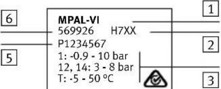 4 4 |  Proc. Cont. Eq.E3223461: -0.9 - 8 bar12, 14: 3 - 8 bar24 V | max: 6 ADE-73734 Esslingen Proc. Cont. Eq.E3223461: -0.9 - 8 bar12, 14: 3 - 8 bar24 V | max: 6 ADE-73734 Esslingen | 1Order code |
| 2Serial number with production period (encrypted → Chap.Production period) | ||
| 3Technical data → Appendix A.1 | ||
| 4Product designations and certification-specific technical data | ||
| 5Test number (serial number) | ||
| 6Part number | ||
Tab. 2 Product labelling (rating plate) of the product
Production period
In the product labelling, the first two characters of the serial number indicate the production period in encrypted form Tab. 2, 2. The letter indicates the production year and the next characters (numeral or letter) indicates the production month.
Production year
| H = 2016 | J = 2017 | K = 2018 | L = 2019 | M = 2020 | N = 2021 |
| P = 2022 | R = 2023 | S = 2024 | T = 2025 | U = 2026 | V = ... |
Tab. 3 Production year
| Production month | ||||
| 1 January 2 February | August | |||
| 3 March 4 April | ||||
| 5 May 6 June | ||||
| 7 July | 8 | August | ||
| 9 September | 0 | October | ||
| N | November | D | December | |
Tab. 4 Production month
Specified standards
| Version status | ||
| IEC 60204-1:2005-10 | EN 60529:1991-10 | |
| ISO 228-1:2000-09 | EN 61000-6-2:2005-08 | |
| ISO 5599-1:2001-08 | EN 61000-6-4:2007-01 + A1:2011-02 | |
| ISO 8573-1:2010-04 | DIN 51524-1...3:2006-04 | |
Tab. 5 Specified standards
1 Safety
1.1 Safety instructions
- Switch off the power supply before mounting and installation work. Only switch on the power supply when mounting and installation work is completely finished.
- Never unplug or plug in a product when it is energised!
- Observe the handling specifications for electrostatically sensitive devices.
1.2 Intended use
Valve terminal MPAL-VI is intended for installation in machines and automation technology systems and must be used exclusively as follows:
– In perfect technical condition
– In its original state without unauthorised modifications; the conversions or modifications described in the documentation are permitted
- Within the product's limits as defined by the technical data Appendix A.1,
- Only in combination with approved components (e.g. valves, drive/displacement encoder combinations)
– In an industrial environment
Use for intended purpose is described completely in the documentation. Every other use is considered not intended.
1.3 Requirements for product use
- Make the documentation available to the design engineer, installer and personnel responsible for commissioning the machine or system in which this product is used.
- Make sure that the specifications of the documentation are always complied with. Also consider the documentation for the other components and modules.
• Take into consideration the legal regulations for the destination:
– Regulations and standards
– Regulations of the testing organisations and insurers
– National specifications
1.3.1 Technical prerequisites
General conditions for the correct and safe use of the product, which must be complied with at all times:
- Comply with the connection and ambient conditions of the product and all connected components specified in the technical data Appendix A.1.
Only full compliance with the limit values and load limits permits operation of the product in accordance with the relevant safety regulations.
- Observe the instructions and warnings in the documentation.
1 Safety
1.3.2 Requirements of specialised personnel
The product may be commissioned only by a qualified electrical technician who is familiar with the following topics:
- Installation and operation of control and automation systems
– Applicable regulations for operating safety-engineering systems
– Applicable regulations for accident prevention and occupational safety
– Documentation for the product
1.3.3 Range of applications and certifications
Safety-related standards and test values with which the product complies and which it satisfies can be found in the Technical Data
→ Appendix A.1. Product-relevant EC directives are itemised in the declaration of conformity.

Certificates and declaration of conformity for the product → www.festo.com/sp
The product fulfils the requirements of EU directives and is marked with the CE marking.

Certain configurations of the product have been certified by Underwriters Laboratories Inc. (UL) for the USA and Canada. These configurations bear the following mark:

US LISTED
UL Listed Mark for Canada and the United States

Note
Observe the following if the UL requirements are to be complied with:
- Rules for complying with the UL certification are itemised in the separate UL-specific special documentation.
– The technical data listed there takes precedence. This data may vary from the technical data mentioned here.
2 Product overview
2.1 Purpose
The valve terminal is based on a modular structure and creates the following connections:
– Common ducts for supply and exhaust air
– Electrical connections for supply and communication between all solenoid coils
Working lines (2) and (4) are provided for each valve position on the individual sub-bases. The valves are supplied with compressed air (operating pressure and pilot pressure) via the common ducts and connections in the supply modules. The exhaust air (from the valves and the pilot exhaust) is also exhausted via these common ducts and connections.
The valve terminal can be supplemented by additional supply modules, e.g. to supply pressure zones. The functional scope of a valve position can be extended by vertical stacking, e.g. for pressure regulation.
Depending on the types of valve used, the following valve terminal operating modes can be used:
– Standard operation with one or more pressure zones
- Reversible operation with compressed air supply via connections (3), (5) and exhaust via port (1)
– Low-pressure operation at 0 ... 3 bar

Further information on the valve operating modes → Appendix B
2.2 Overview of components

1Electrical connection - left end plate
2 Supply module
3 Sub-base with electrical interlinking module and valve or blanking plate
4 Combination of sub-bases with 4-way electrical interlinking module and valves or blanking plates
5 Vertical stacking
6Right end plate
Fig. 2.1 Electrical connection and pneumatic components on the valve terminal - example
2.3 Electrical connection
2.3.1 Multi-pin plug connection
The electrical connection of the valve terminal is made centrally via a multi-pin plug connection in the left end plate.
Depending on the type of connector on the multi-pin plug connection, a maximum of 32 solenoid coils can be controlled inside the valve terminal Tab. 2.1. Each solenoid coil occupies a pin on the multi-pin plug connection.

1 Multi-pin plug connection (here: Sub-D connector with 25 pins)
2 Multi-pin connection cable (here: with IP65/67 cover)
Fig. 2.2 Electrical connection for the valve terminal via multi-pin plug - example
Connector types

Pin assignment and core colours on the multi-pin connection line differ depending on version → Brief description VMPAL-EPL-SD.../-FL.../-KL...
| Multi-pin plug connection Plug type Number of controllable | solenoid coils | ||
 | Sub-D connector with 9 pins 8 | ||
 | Sub-D connector with 25 pins 24 | ||
 | Sub-D connector with 44 pins 32 | ||
 | Terminal strip with 33 pins 32 | ||
 | Flat cable plug connector with 40 pins | 32 | |
Tab. 2.1 Types of plugs on the multi-pin connection
Cover types
The following types of cover are available for the multi-pin plug connections with Sub-D plugs:
| Type of cover | Characteristics |
IP65/67 – Closed cover with seal | – Degree of protection IP65/67– Connection on side or at front– Preconfigured cable or can be configured by customerThe IP65/67 cover is only available for the following types of connector on the multi-pin plug connection:– Sub-D connector with 25 pins– Sub-D connector with 44 pins |
IP40 – Open cover | – Degree of protection IP40(here: Sub-D plug with 25 pins)The IP40 cover is available for all types of connector on the multi-pin plug connection → Tab. 2.1. |
Tab. 2.2 Types of cover for multi-pin connections with Sub-D plugs
2.3.2 CPX terminal
The electrical connection from the valve terminal to the CPX terminal takes place through the pneumatic interface. The pneumatic interface replaces the left end plate on the valve terminal.
Depending on the switch setting of the rotary switch on the pneumatic interface, within the valve terminal a maximum of 32 solenoid coils can be controlled.

1 CPX bus node
2 Pneumatic interface
③Optional: other CPX modules
4 Left end plate on the CPX terminal
Fig. 2.3 Electrical connection of valve terminal via CPX terminal - example
2.3.3 I-Port/IO-Link interface
The electrical connection of the valve terminal is provided by the I-Port/IO-Link interface and by 5-pin connecting cables. Via the I-Port/IO-Link interface, a maximum of 32 solenoid coils can be activated in the valve terminal.
The valve terminal can be installed centrally or decentrally:

1Bus nodes CTEU
4 Electrical connecting plate with bus node CTEU
2 End plate with I-port/IO-Link interface
5 Valve terminal
3 Connecting cable
Fig. 2.4 Electrical connection of valve terminal via I-Port/IO-Link interface - example
Central installation
A bus node CTEU is mounted directly on the end plate with I-Port/IO-Link interface.
Decentralised installation
A bus node CTEU is mounted on an electrical sub-base. The electrical sub-base is connected to the end plate with I-Port/IO-Link interface by a connecting cable.
This connecting cable must not be longer than 20 m.
2.4 Pneumatic components
2.4.1 Sizes
The components of the valve terminal are available in the following sizes:
- MPA1: Size 10 mm
- MPA14: Size 14 mm
- MPA2: Size 20 mm
2.4.2 Valves
The valve terminal can be equipped with the following valves:
- 2x 2/2-way valves
- 2x 3/2-way valves
-3/2-way valves - 5/2-way valves
-5/3-way valves
Unassigned valve locations can be sealed with blanking plates.
Identification of the valves
ID codes are printed on the tops of the valves. These ID codes enable equipment items on the valve terminal to be identified.
ID code Valve assembly
| B 5/3-way valve, mid-position open, mechanical spring return | |
| D Two single solenoid 2/2-way valves, normally closed, pneumatic spring return | |
| DS Two single solenoid 2/2-way valves, normally closed, mechanical spring return | |
| E 5/3-way valve, mid-position exhausted, mechanical spring return | |
| G 5/3-way valve, mid-position closed, mechanical spring return | |
| H Two single solenoid 3/2-way valves, control side 12 normally open, control side 14 normally closed, pneumatic spring return | |
| HS Two single solenoid 3/2-way valves, control side 12 normally open, control side 14 normally closed, mechanical spring return | |
| HU Two 3/2 polymer poppet valves, control side 12 normally open, control side 14 normally closed, mechanical spring return | |
| I | Two 2/2-way valves, normal position closed, pneumatic spring return- In 2-pressure operation:Operating pressure via port (1) or port (5)- For vacuum operation:Operating pressure via port (1), vacuum at port (5) |
| J | 5/2-way double solenoid valve |
| K | Two single solenoid 3/2-way valves, normally closed, pneumatic spring return |
| KS | Two single solenoid 3/2-way valves, normally closed, mechanical spring return |
| KU Two 3/2 polymer poppet valves, normally closed, mechanical spring return | |
| L | Blanking plate for sealing an unused valve position |
| ID code Valve assembly | |
| M Single solenoid 5/2-way valve, pneumatic spring return | |
| MS Single solenoid 5/2-way valve, mechanical spring return | |
| MU Single solenoid 5/2-way polymer poppet valve, mechanical spring return | |
| N Two single solenoid 3/2-way valves, normally open, pneumatic spring return | |
| NS Two single solenoid 3/2-way valves, normally open, mechanical spring return | |
| NU Two 3/2 polymer poppet valves, normally open, mechanical spring return | |
| W Single solenoid 3/2-way valve, normally open, external compressed air supply via port (2), pneumatic spring return | |
| X Single solenoid 3/2-way valve, normally closed, external compressed air supply via port (4), pneumatic spring return | |
Tab. 2.3 ID codes of the valves

- Display and operating elements Chap. 2.6.3
– Circuit symbol → Appendix B.1 - Pressure ranges Appendix A.1.3
2.4.3 Supply module


natural_image
Technical line drawing of a mechanical device with internal components and mounting holes (no text or symbols)1Supply module
2 Flat plate silencer
3 Exhaust plate for ducted exhaust air
Fig. 2.5 Supply module
The supply module can be used for the following applications:
- Main supply of operating pressure to the valve terminal
– Additional supplies, e.g. to increase pressurisation and exhaust performance
– Common exhausting of exhaust air ducts (3) and (5) for working air via a flat plate silencer or an exhaust air plate for ducted exhaust air
The exhaust air plate for ducted exhaust air can be used in reversible mode to supply pressure.

- Main and auxiliary power supply Chap. 2.8.1
- Exhaust air Chap. 2.8.2
- Pressure zone formation Chap. 2.8.6
- Address assignment → Chap.2.9
2.4.4 Right end plates


① Right end plate without supply ports
2 Right end plate with supply ports
Fig. 2.6 Right end plates
The right end plate without supply ports can be used for the following purposes:
- Internal and external pilot air supply
- Exhausting of pilot air (82/84) via a silencer or as ducted exhaust air

If a right end plate without supply ports is used, a separate supply module is needed for the main supply of operating pressure to the valve terminal.
The right end plate with supply ports can be used for the following purposes:
– Main supply of operating pressure to the valve terminal
- Internal and external pilot air supply
- Separate exhausting of exhaust air ducts (3) and (5) for working air
- Exhausting of pilot air (82/84) via a silencer or as ducted exhaust air

- Main and auxiliary power supply Chap. 2.8.1
- Exhaust air Chap. 2.8.2
– Pilot air supply → Chap. 2.8.4 - Pressure zone formation Chap. 2.8.6
2.4.5 Sub-bases


1 Sub-base
2Electrical interlinking module
3 Combination of sub-bases
44-way electrical interlinking module
Fig. 2.7 Sub-bases
The individual sub-bases are built on a modular structure and they supply the valves pneumatically. The electrical interlinking module in the sub-bases supplies electrical power to the valves.
As an alternative to the individual sub-bases, 4 sub-bases of the same size can be combined with one another (size 10 mm or size 14 mm). These 4 sub-bases are connected by a 4-way electrical interlinking module and are screwed together.
Sub-bases with pressure zone separation
To supply valves with different pressures, pressure zones can be formed in the valve terminal. Sub-bases with pressure zone separation divide the supply duct (1) or the exhaust air ducts (3) and (5).
Pressure zone separation of pilot ducts (12) and (14) is not intended → Section 2.8.4.
Sub-bases with pressure zone separation exist in the following variants:
| Coding | Variant | |
 | VMPAL-AP-...-T1Duct (1) separated | |
 | VMPAL-AP-...-T35Ducts (3) and (5) separated | |
 | VMPAL-AP-...-T135Duct (1) separatedDucts (3) and (5) separated | |
Tab. 2.4 Variants of the sub-bases with pressure zone separation

- Pressure zone formation Chap. 2.8.6
- Address assignment → Chap.2.9
2.4.6 Pressure regulator plates

natural_image
Technical line drawing of a mechanical component with no visible text or symbolsFig. 2.8 Pressure regulator plate, type VMPA...B8-R...C2-C-... with optional pressure gauge
A pressure regulator plate with adjustable pressure regulator can be installed between the sub-base and the valve in order to control the force of the connected actuators. The pressure regulator maintains a constant output pressure (secondary side) independent of pressure fluctuations (primary side) and air consumption.
Identification of the pressure regulator plates
ID codes are printed on the sides of the pressure regulator plates. These ID codes enable equipment items on the valve terminal to be identified.
| Vertical stacking component | ID code | Control range | Connection | Size |
| Pressure regulator plate P | PA | 0.5 ... 10 bar | (1) | MPA1, MPA2 |
| PF 0.5 ... 6 bar | ||||
| Pressure regulator plate A | PB | 2 ... 10 bar | (4) | MPA1, MPA2 |
| PG 2 ... 6 bar | ||||
| Pressure regulator plate B | PC | 2 ... 10 bar | (2) | MPA1, MPA2 |
| PH 2 ... 6 bar | ||||
| Reversible pressure regulator plate A | PK | 0.5 ... 10 bar | (4) | MPA2 |
| PM | 0.5 ... 6 bar | |||
| Reversible pressure regulator plate B | PL 0.5 ... 10 bar (2) MPA2 | |||
| PN 0.5 ... 6 bar | ||||
| Pressure gauge for pressure regulator plate | T | |||
| Feature A pressure regulator | B pressure regulator | P pressure regulator | Reversible A pressure regulator | Reversible B pressure regulator |
| Setting the pressure regulator | ||||
| Setting the pressure regulator | The pressure regulator can only be adjusted in switched state | The pressure regulator can be adjusted in any state | ||
| Valves | ||||
| Requirements for valves | Quick-exhaust valve essential | — Reversible valves required | ||
Tab. 2.5 ID codes for pressure regulator plates
Tab. 2.6 Pressure regulator variants

Examples of pressure control

1 Pressure regulator
3 Pressure regulator plate
2Valve
4 Sub-base
Fig. 2.9 Pressure control with a B pressure regulator - example

1 Reversible pressure regulator
3 Pressure regulator plate
2 Reversible operated valve
4 Sub-base
Fig. 2.10 Pressure control with a reversible B pressure regulator - example
2.4.7 Vertical pressure shut-off plate

natural_image
Technical line drawing of a mechanical component with mounting holes and internal slots (no text or symbols)Fig. 2.11 Vertical pressure shut-off plate, type VMPA1-HS
To be able to shut down the operating pressure on a valve separately, a vertical pressure shut-off plate can be installed between sub-base and valve. The vertical pressure shut-off plate makes it possible to change the valve without shutting down the operating pressure for the valve terminal.

The vertical pressure shut-off plate is available for the 10 mm size.
- Operating elements Chap. 2.6.7
- Circuit symbols for the vertical pressure shut-off plate Appendix B,Tab. B.7
- Installation of the vertical pressure shut-off plate Assembly instructions VMPA1-HS
2.4.8 Vertical pressure supply plate

natural_image
Technical line drawing of a mechanical component with internal cavities and mounting holes (no text or symbols)Fig. 2.12 Vertical supply plate, type VMPA2-VSP- ...
To be able to supply an individual valve with individual operating pressure, a vertical pressure supply plate can be installed between sub-base and valve. The exhaust and pilot air supply of the valve are provided via the central connections on the valve terminal.

The vertical supply plate is available for the 20 mm size.
- Main and auxiliary power supply Chap. 2.8.1
- Switching symbols for the vertical supply plate Appendix B, Tab. B.8
2 Product overview
2.4.9 Fixed flow restrictor

①Fixed flow restrictor ②Retainer for fixed restrictor
Fig. 2.13 Fixed flow restrictor
To set the exhaust flow rate in exhaust air ducts (3) and (5), a fixed flow restrictor can be installed between sub-base and valve. With fixed flow restrictors, it is for example possible to limit the cylinder speed in advance in response to known flow rate conditions.

Per duct, either a fixed flow restrictor or a check valve can be installed.
Fixed flow restrictors are available for the 10 mm size.
- Installation of the fixed flow restrictor Assembly instructions VMPA1-FT-NW...-10
- Flow rates with fixed flow restrictor Appendix A, Tab. A.5
2 Product overview
2.4.10 Check valves

natural_image
Technical line drawing of a mechanical housing or enclosure with internal components and a labeled component (no text or symbols present)1 Check valve
Fig. 2.14 Check valve – example of a check valve for the 14 mm size
A check valve can be integrated between sub-base and valve to prevent unintended switching of actuators in response to high back pressure in the exhaust air ducts (3) and (5). If there is a high level of back pressure, the check valves seal off exhaust air ducts (3) and (5).

Per duct, either a fixed flow restrictor or a check valve can be installed.
- Mounting of the check valves Assembly instructions VMPA...RV
2.5 Connecting components
2.5.1 Pneumatic connecting components

1 Common exhaust port "Valves" (3/5)
② Pilot air connections (12/14) and (82/84) are dependent on the design of the right end plate → Chap. 2.4.4
3 Supply connections "Operating pressure" (1)
4 Working ports (2) and (4), per valve
Fig. 2.15 Pneumatic connecting components on the valve terminal
2.5.2 Electrical connecting components

1 Multi-pin plug connection
(here: Sub-D connector with 25 pins)
2 Earth terminal
for connection to functional earth
Fig. 2.16 Electrical connecting components on the valve terminal with multi-pin plug connection

1 I-Port/IO-Link interface (M12 connector, A-coded)
3 Earth terminal (optional) for connection to functional earth
2 Earthing screw (Torx, T20) for connection to functional earth
Fig. 2.17 Electrical connection components on the valve terminal with I-Port/IO-Link interface

Valve terminal with CPX terminal:
- Information about the electrical connecting components System description of the CPX terminal
- Information about earthing Chap. 3.7
2.6 Display and operating elements
2.6.1 Valve terminal

1 Switching status indicator of the valves (yellow LEDs)
2 Manual override (on each magnetic coil, non-denting or detenting
3 Inscription label
4 Slot for inscription label holder → Chap. 3.2
5 Fault LED on the pneumatic interface → Chap. 2.6.8
Fig. 2.18 Display and operating elements - example of the valve terminal with CPX terminal

Information on the display elements of the CPX terminal can be found in the system description of the CPX terminal
2.6.2 Left end plate with I-Port/IO-Link interface

natural_image
Technical line drawing of an industrial control unit with multiple terminal blocks and mounting holes (no text or labels)1 Status LED X1
Fig. 2.19 Display components on the left end plate with I-Port/IO-Link interface

Statuses of the status LEDs on the left end plate with I-Port/IO-Link interface → Chap. 5.3
2 Product overview
2.6.3 Switching status indication of the valves
Each solenoid coil has an LED and a manual override. LEDs and manual overrides are assigned to the solenoid coils as follows:

1 LED for solenoid coil 12
3 Manual override for valve solenoid coil 12
2 LED for solenoid coil 14
4 Manual override for valve solenoid coil 14
Fig. 2.20 Assignment of LEDs and manual overrides for the solenoid coils

Switching positions of the valves → Chap. 5.1
2.6.4 Manual override
When the pressure supply is switched on, the manual override can be used to switch a valve to an electrically unactuated, de-energised state. The manual override should primarily be used when commissioning the pneumatic system in order to check the functional and operational performance of the valve or of the valve-actuator combination.

Testing the valves and the valve/actuator combination → Chap.4.2
2.6.5 Cover cap for manual override VAMC-L1-CD

natural_image
Technical line drawing of a mechanical component with no visible text or symbols1 Slide on cover cap for manual override VAMC-L1-CD
Fig. 2.21 Operating element of the cover cap for the manual override VAMC-L1-CD
2.6.6 Pressure regulator plate

1 Adjusting screw for pressure regulator plate
3Connection for pressure gauge (rotatable)
2 Pressure gauge (optional)
Fig. 2.22 Display and operating elements on the pressure regulator plates - example MPA1
2 Product overview
2.6.7 Vertical pressure shut-off plate

natural_image
Technical line drawing of a mechanical component with mounting holes and a labeled part (no text or symbols present)1 Actuating element for the vertical shut-off plate
Fig. 2.23 Operating element for the vertical shut-off plates
2.6.8 Pneumatic interface

1 Connecting plug to the pneumatic modules
2 Rotary switch under a cover cap (tightening torque: 0.5 Nm ± 10 %).
3 Inscription label
Fig. 2.24 Display and connecting components on the pneumatic interface
4 Fault LED (red)
5 Connecting plug to the CPX interlinking blocks

- Number of controllable solenoid coils on the rotary switch Chap. 2.9.3
- Statuses of fault LEDs on the pneumatic interface Chap. 5.2
2.7 Inscription system
components
 | Inscription label for the pneumatic interface | |
 | Inscription label holder for sub-bases,type VMPAL-ST-AP-... (optional)Mounting the inscription label holder → Chap. 3.2 | |
 | Inscription label holder for valves, type ASLR-D-L1 (optional)Mounting the inscription label holder→ Assembly instructions ASLR-D-L1 | |
Tab. 2.7 Inscription system

Accessories → www.festo.com/catalogue
2.8 Functional description
2.8.1 Main and auxiliary power supply
The main supply of the valve terminal with operating pressure can be provided via a supply module
(→ Fig. 2.5) or via a right end plate with supply ports (→ Fig. 2.6).
For additional supplies, supply modules or vertical supply plates can be used.
Additional supplies may be required in the following typical cases:
– The valve terminal has several pressure zones.
- Many valves on a valve terminal are simultaneously switched to being pressurised or exhausted.
2.8.2 Exhaust air
The exhaust air ducts (3) and (5) for the working air can be exhausted in the following manner:
– Common exhausting via a supply module with a flat plate silencer or via an exhaust air plate for ducted exhaust air
– Separate exhausting via a right end plate with supply ports
The pilot exhaust air (82/84) is exhausted via a port on the right end plate.
2.8.3 Vacuum or low-pressure operation
– Vacuum operation: vacuum ( -0.9 0 bar) at supply port (1)
– Low-pressure operation: low pressure (0 ... 3 bar) at supply port (1)
The following conditions must be fulfilled:
– The valve terminal is operated with an external pilot air supply.
- The valve terminal is equipped with vacuum-compatible or low-pressure-compatible valves. Valves that are not vacuum-compatible or low-pressure-compatible are operated via separate pressure zones.
| Pressure zone Valves | |
| Pressure zone with vacuum or low pressure supply via supply port (1) | The pressure zone is only equipped with vacuum-compatible or low-pressure-compatible valves → Appendix A.1.3 and Appendix B.1 |
| Pressure zone with overpressure supply via supply port (1) → Appendix A Fig. A.1 | The pressure zone can also be fitted with the following valves which are not vacuum- or low-pressure-compatible: - 2x 3/2-way valves (ID codes H, K and N) - 2x 2/2-way valves (ID codes D and I) |
Tab. 2.8 Valves compatible with vacuum or low pressure
Valves for the switching of vacuum
- Install a filter in the suction line to prevent malfunctions caused by foreign matter sucked into the line.
| Feature 2x 2/2-way valve (ID code I) | 3/2-way valve (ID code W) | 3/2-way valve (ID code X) | |
| Switch on the vacuum From port (5) to port (4) with solenoid coil 14 | From port (2) to port (4) From port (4) to port (2) | ||
| Operating pressure at supply port (1) | As an ejection pulse switched to port (2) with solenoid coil 12 | With additional supply: independent of supply port (1) | |
| Exhaust air through port | (5) (3) | ||
Tab. 2.9 Valves for the switching of vacuum

Note
2x 2/2-way valve (ID code I)
- If the valve terminal is also equipped with other valves, then operate vacuum-compatible or low-pressure-compatible valves in a separate pressure zone with separate exhaust duct (5).

Pressure ranges of the valve types → Appendix A.1.3
2.8.4 Pilot air supply
All pressure zones at the valve terminal are supplied with pilot air via the right end plate. With the coding cover on the right end plate, the type of pilot air supply can be set Chap. 7.6 Mixed operation with internal and external pilot air is not intended.
| Feature Internal pilot air supply | External pilot air supply | |
| Setting of the pilot air selector | “Int” “Ext” | |
| Type of pilot air supply Pilot air | supply is branched internally from port (1). | Pilot air is supplied externally via port (12/14). |
| Special features of the creation of pressure zones | If the valve terminal has several pressure zones, the pilot air is taken from the pressure zone, which is directly adjacent to the right end plate. | None |
| Required control pressure at port (12/14) | → Diagrams in Appendix A, Fig. A.1 ... Fig. A.6 | |
| Feature External pilot air supply | Internal pilot air supply | |
| Operating pressure at port (1) | The operating pressure in the pressure zone immediately adjacent to the right end plate is in the required control pressure range (3 ... 8 bar). | The operating pressure must not drop below 3 bar, nor rise above 8 bar. |
| Vacuum or low-pressure operation | Not possible Possible | |
| Slow pressure build-up in the overall supply | → Chap. 3.6.1 | |
Tab. 2.10 Types of pilot air supply

Recommendation: Operate valve terminal with external pilot air supply, e.g. to compensate for fluctuations in operating pressure.
2.8.5 Reverse operation
In reverse operation, the supply duct and the exhaust air ducts are interchanged:
- Compressed air supply via duct (3/5)
- Exhausting via duct (1).
The following conditions must be fulfilled:
- The valve terminal is equipped with valve types that are suitable for reverse operation
→ Appendix B.1.
- The valve terminal is operated with an external pilot air supply.
- The operating pressure of the valve terminal is within the range of -0.9 ... 8 bar.
2.8.6 Creation of pressure zones
To supply valves with different operating pressures, pressure zones can be created in the valve terminal. A total of up to 20 pressure zones can be created.
To operate vacuum- or low-pressure-compatible valves with other valves, pressure zones are essential → Chap. 2.8.3.
Sub-bases with pressure zone separation divide the supply duct (1) and/or the exhaust air ducts (3) and (5) → Chap. 2.4.5).
A pressure zone starts to the right of the sub-base with pressure zone separation and requires its own pressure supply. Compressed air can be supplied and exhausted via a supply module or the right end plate. Additional supplies can be installed at any desired position within a pressure zone Fig. 2.25 and Fig. 2.26.

1 Pressure zone 1
2 Pressure zone 2
3 Pressure zone 3
4 Right end plate (here: version without lateral ports)
5 Supply module (here: for pressure zone 1)
6 Designation of sub-base with pressure zone separation (here: duct (1) and duct (3/5) separated between pressure zones 1 and 2)
Fig. 2.25 Valve terminal with 3 pressure zones - example

(here: version with side ports (1), (3) and (5) for pressure zone 4)
6 Supply module (here: for pressure zone 1)
7 Designation of sub-base with pressure zone separation (here: duct (1) separated between pressure zones 1 and 2)
Fig. 2.26 Valve terminal with 4 pressure zones - example
2.8.7 Vertical stacking
To extend the functional scope of a valve position, vertical stacking components can be installed between sub-base and valve.
components

natural_image
Technical line drawing of a mechanical assembly with no visible text or symbols
natural_image
Technical line drawing of a mechanical component with mounting holes and internal channels (no text or symbols)
natural_image
Isometric line drawing of a mechanical component with internal slots and mounting holes (no text or symbols)Pressure regulator plate, type VMPA...B8-R...C2-C-... → Chap. 2.4.6
Vertical pressure shut-off plate, type VMPA1-HS → Chap. 2.4.7
Vertical supply plate, type VMPA2-VSP-... → Chap. 2.4.8
Tab. 2.11 Vertical stacking
2.9 Address assignment of valve positions
Addresses are allocated in ascending order without gaps, from left to right. Depending on the integrated electrical interlinking module, a valve position occupies the following number of addresses:
| Electrical interlinking module | Number of occupied addresses per valve position | Number of valve positions | |
| Type Housing colour | |||
| Individual electrical interlinking module | |||
| VMPAL-EVAP-...-1 Grey 1 1 | |||
| VMPAL-EVAP-...-2 Black 2 1 | |||
| 4-way electrical interlinking module | |||
| VMPAL-EVAP-...-1-4 Grey 1 4 | |||
| VMPAL-EVAP-...-2-4 Black 2 4 | |||
| Electrical interlinking module of the power supply module | |||
| VMPAL-EVAP-20-SP Black 0 | (signals are passed through) | 0 | |
Tab. 2.12 Address assignment of the valve positions

Address assignment does not depend on whether the module is equipped with blanking plates or valve plates.
At all valve positions valves with 1 or 2 solenoid coils can be fitted.
If one valve occupies both addresses of a valve position:
– Solenoid coil 14 occupies the lower-value address.
– Solenoid coil 12 occupies the higher-value address.
Valves with a magnetic coil also occupy the second address of a valve position, if provided.

If the left valve terminal was extended from the last valve position, addresses can get reassigned accidentally.
Example of address assignment

1Addresses of the solenoid coils 14
2Addresses of the solenoid coils 12
3Reserved valve position
4 Sub-base with electrical interlinking module VMPAL-EVAP-10-2 occupies 2 addresses per valve position
5 Sub-base with electrical interlinking module VMPAL-EVAP-10-1 occupies 1 address per valve position
6 Combination connection block with 4-way electrical interlinking module VMPAL-EVAP-10-2-4 occupies 4x2 addresses at each valve position
7 Supply module with electrical interlinking module VMPAL-EVAP-20-SP does not assign any address
Fig. 2.27 Address assignment: Valve terminal with multi-pin connection (plan view) – example
| Pin Address Valve position no. Solenoid coil Electrical interlinking | ||||
| 1 | 0 | 0 | 14 | VMPAL-EVAP-10-2-4(black, for 4 MPA1 valves, each with 2 solenoid coils) |
| 2 | 1 | 12 | ||
| 3 | 2 | 1 | 14 | |
| 4 | 3 | 12 | ||
| 5 | 4 | 2 | 14 | |
| 6 | 5 | 12 | ||
| 7 | 6 | 3 | 14 | |
| 8 | 7 | 12 | ||
| 9 | 8 | 4 14 VMPAL-EVAP-1 | 0-2-4 | (black, for 4 MPA1 valves, each with 2 solenoid coils) |
| 10 | 9^1) | |||
| 11 | 10 | 5 | 14 | |
| 12 | 11 | 12 | ||
| 13 | 12 | 6 | 14 | |
| 14 | 13 | 12 | ||
| 15 | 14^1) | 7-- | ||
| 16 | 15^1) | -- | ||
| 17 16 | 8 14 VMPAL-EVAP-10-1 | (grey, for 1 MPA1- valve with 1 solenoid coil) | ||
| 18 | 17 | 9 | 14 | VMPAL-EVAP-10-2(black, for 1 MPA1 valve with 2 solenoid coils) |
| 19 | 18 | 12 | ||
| ... ... ... | ... | ... | ||
| 25 0 V/24 V ^2) | ||||
1) Address is reserved for a solenoid coil by the electrical interlinking module, not used in the current example.
2) 0 V with positive-switching control signals; in the case of negative-switching control signals, connect 24 V; mixed operation is not permitted!
Tab. 2.13 Address assignment: valve terminal with multi-pin connection - example
2.9.1 Valve terminal with multi-pin plug connection:
Dependent on the plug type of the multi-pin plug connection, within the valve terminal a maximum of 32 solenoid coils can be actuated → Chap. 2.3.1, Tab. 2.1. Each solenoid coil occupies a pin on the multi-pin plug connection.
2.9.2 Valve terminal with I-Port/IO-Link interface:
Within the valve terminal, a maximum of 32 solenoid coils can be actuated.
2.9.3 Valve terminal with CPX terminal
Depending on the switch setting of the rotary switch on the pneumatic interface, within the valve terminal a maximum of 32 solenoid coils can be controlled. Each solenoid coil occupies one output address on the CPX terminal. If not all output addresses are assigned by solenoid coils, the surplus output addresses are reserved.
| Rotary switch | Switch setting Number of controllable solenoid coils | |
 | 0 | 4 |
| 1 | 8 | |
| 2; 3 16 | ||
| 4; 5; 6; 7 24 | ||
| 8 (delivery status) 32 | ||
| 9 | 32 | |
Tab. 2.14 Set the number of solenoid coils that can be actuated

Addressing of the pneumatic components of the CPX terminal
→ System description for CPX terminal, table “Descriptions of the CPX terminal”
3 Mounting and installation
3 Mounting and installation
3.1 Mounting on H-rails and walls

Note
- Mount the valve terminal with sufficient space for heat dissipation.
- Stay within permitted temperature ranges → Appendix A, Tab. A.2

- Valve terminal with multi-pin plug connection or I-Port/IO-Link interface
→ Assembly instructions for valve terminal MPA
- Valve terminal with CPX terminal Assembly instructions for terminal CPX/valve terminal MPA
3.2 Inscription label holder, mounting/dismounting
An optional inscription label holder can be mounted on the sub-bases to label the valves or working lines.

Accessories → www.festo.com/catalogue
Mounting
- Press the inscription label holder into the recess of the sub-bas until it engages.
- Press the label into the label holder from above.

1 Label, type IBS-6X10
2 Recess in the sub-bas
Fig. 3.1 Mounting the inscription label holder
③ Label holder, type VMPAL-ST-AP-...
3 Mounting and installation
Dismounting
- Lift inscription label holder off sub-base with a slotted screwdriver.

natural_image
Technical line drawing of a mechanical assembly with a screwdriver inserted, showing no text or symbols1 Inscription label holder with label
Fig. 3.2 Dismounting the inscription label holder
3.3 General installation instructions

Warning
Uncontrolled movements of the connected actuator technology and loose tubing can cause injury to persons and/or damage to property.
- Before carrying out mounting, installation and maintenance work, switch off the following power sources:
- Compressed air supply
- Operating voltage supply
- Load voltage supply

Electrostatically sensitive components:
Do not touch electrical and electronic components.

Note
- Handle all modules and components carefully.
- Screws must be placed so that the self-cutting threads can be used.
- Only tighten the screws by hand.
- Comply with tightening torques.
- Secure all of the components without distortion and mechanical tension.
- Replace damaged seals.
- Keep mounting surfaces clean and dry.
3.4 Compressed air preparation

Note
Unfiltered or incorrectly lubricated compressed air will reduce the service life of the valve terminal.
3.4.1 Operation with unlubricated compressed air

Note
An excess of residual oil content in the compressed air will cause valves to malfunction, and will cause the life-time lubrication necessary for unlubricated operation to be washed out.
- Maintain the residual oil content
– Bio-oils (oils based on synthetic or natural ester, e.g. rapeseed oil methyl ester):
Residual oil content max. 0.1 mg/m ^3 → ISO 8573-1:2010 [−:−:2]
– Mineral oils (e.g. HLP oils acc. to DIN 51524, Parts 1 to 3) or similar oils based on polyalphaolefins (PAO):
Residual oil content max. 5 mg/m ^3 → ISO 8573-1:2010 [−:−:4]
3.4.2 Operation with lubricated compressed air

Note
Operation with lubricated compressed air will cause the life-time lubrication, which is necessary for unlubricated operation, to be washed out.
If the system was commissioned with lubricated compressed air, a changeover to unlubricated compressed air is not possible.

Operation with unlubricated compressed air protects the environment. Festo pneumatic valves and actuators, if used as intended, require no additional lubrication and still achieve a long service life.
If lubricated compressed air is absolutely essential, the quality of compressed air prepared with the compressor must correspond to that of unlubricated compressed air.
- Do not operate the entire system with lubricated compressed air.
- Install the lubricators for dispensing additional oil directly upstream of the consuming actuators.

Note
Incorrect supplementary oil and an oil content in the compressed air that is too high will cause malfunctions in the valves and will reduce the service life of the valve terminal.
- Use Festo special oil OFSW-32 or the other oils listed in the Festo catalogue (conforming to DIN 51524-HLP32, basic viscosity 32 CST at 40^ ).
- Comply with the limit value for supplementary lubrication: max. 25 mg/m ^3 → ISO 8573-1:2010 [—:—:5]
- Check lubricator setting.
Setting the lubricators
With the machine running (typical operating status), optionally:
-0.2 to max. 1 drop/min
- 0.5 to 5 drops/1000 l air
Check lubricator setting

Check the service units for condensate and lubricator setting twice a week.
- Determine the actuator which is furthest from the lubricator.
- Determine the valve terminal which controls this actuator.
- Remove the silencer, if present, from port (3) or (5).
- Hold a piece of white cardboard at a distance of 10 cm from the exhaust port.
- Let the system run for some time.
- Check the discolouration of the cardboard:
If the cardboard is discoloured slightly (yellow), the lubricator is set correctly.
Indications for excessive lubrication include:
-
Dripping oil
– A distinctly yellow discolouration of the filter element
– Drops of oil at the silencer -
Correct any incorrect lubricator settings. In some circumstances, extensive maintenance measures are required on the pressure supply unit.
3.4.3 Preventing back pressure
When exhausting large-volume actuators or if the exhaust performance is too small, back pressure can build up in the valve terminal's exhaust ducts.
This back pressure can lead to pneumatic actuation of other valves, especially with unswitched 3/2-way valves that are normally closed.
- Optimise pressurisation and exhaust performance of the valve terminal, e.g. with the following measures:
- Bigger tubing diameters
– Additional supplies through supply modules - Exhausting via supply modules with silencer or exhaust plate
- Use pressure zones to separate exhaust ducts Chap. 2.4.4.
• Install check valves in common exhaust lines.

flowchart
graph TD
    A["1"] --> B["2"]
    B --> C["3"]
    C --> D["4"]
    D --> E["5"]
    F["6"] --> G["2"]
    G --> H["6"]
    H --> I["6"]
    I --> J["2"]
    K["2"] --> L["2"]
    L --> M["2"]
    M --> N["2"]
    N --> O["2"]
    P["2"] --> Q["2"]
    Q --> R["2"]
    R --> S["2"]
    S --> T["2"]
    U["2"] --> V["2"]
    V --> W["2"]
    W --> X["2"]
    X --> Y["2"]
    Z["2"] --> AA["2"]
    AA --> AB["2"]
    AB --> AC["2"]
    AC --> AD["2"]
1 First valve terminal
2 Common exhaust lines (3/5)
3 Central control exhaust line (82/84)
4 Central exhaust line (3/5)
5 Second valve terminal
6 Common exhaust lines (82/84)
Fig. 3.3 Preventing back pressure in common exhaust lines
3.5 Connecting the pneumatic lines
Pneumatic lines can be connected up using the following connecting components:
- Threaded connectors
- Unthreaded cartridges Fig. 3.4 and Tab. 3.1

Fig. 3.4 Pneumatic connections of the valve terminal
| Cable Connection code | (ISO 5599) | Connection size (ISO 228) | Connection^1) |
| Compressed air or vacuum, exhaust air | (1)(3), (5) | QSPKG20 Cartridge in the supply module and in the exhaust plate | |
| G^1/4 ” Threaded connector in the right end plate | |||
| External pilot air, ducted pilot exhaust air | (12/14)(82/84) | M7 Threaded connector in the right end plate | |
| Air or vacuum (2) or | (4) QSPKG10 (MPA1) | QSPKG14 (MPA14)QSPKG18 (MPA2) | Cartridge in the sub-base |
1) Depending on what you have ordered, the valve terminal may already be fitted with cartridges or threaded connectors.
Tab. 3.1 Assigning pneumatic connections
3.5.1 Installing or replacing unthreaded cartridges

Caution
Risk of injury through unsecured pressurised parts.
If the wire clamp on the cartridges are not inserted securely in the end position, cartridges can loosen and be ejected at high speed.
• After installation, check that all cartridges are firmly seated.

natural_image
Exploded view diagram of a mechanical assembly showing internal components and assembly steps (no text or labels)Fig. 3.5 Mounting of wire clamps for positive locking of the cartridges
3 Mounting and installation
Installing unthreaded cartridges
- Select the cartridge Tab. 3.1.
- Press cartridge up to the stop in the port and turn it.
- Press and hold down cartridge in this position.
-
Insert wire clamp in the retaining groove:
– With sub-bases: from above or below
– With supply modules: from above
– With exhaust plates on supply modules: from below -
Slide wire clamps over the detent lugs → Fig. 3.5.
-
Check that the cartridge is firmly seated.
Replacing unthreaded cartridges
- If the wire clamps on the cartridges are concealed by valves, remove the valves.
With supply modules: unfasten screws on the exhaust plate or the cover plate of the silencer. Remove the upper part. - Using a narrow slotted screwdriver, lever the wire clamp over the detent lugs and remove it.
- Remove the wire clamp.
- Remove the old cartridge.
- Install a new cartridge.
3 Mounting and installation
3.5.2 Mounting the tubing

1 Cartridge 2 Locking ring
Fig. 3.6 Fitting the tubing
- Press the tube into the tube coupling as far as possible → Fig. 3.4.
- Check the secure attachment of the tube in the cartridge.
- For better system clarity, bundle the installed tubes together with:
- Tube straps
– Multiple tubing holders
- Seal unused connections with blanking plugs.
3.5.3 Dismounting the tubing connection

Warning
If the pneumatic tubing is under pressure when dismounted, it may execute uncontrolled movements, causing injury to persons.
Before disconnecting the pneumatic tubing:
- Switch off the compressed air supply.
- Exhaust the pneumatic tubing.
- Exhaust all actuators controlled by valves that are closed in normal or mid-positions.

1 Cartridge 2 Locking ring
Fig. 3.7 Dismounting the tubing connection
- Label all pneumatic tubing to avoid confusion when reconnecting them.
- Press down the locking ring of the cartridge, e.g. with a screwdriver or with the Festo releasing tool QSO → Fig. 3.7.
- Remove the tubing from the cartridge.

Information about the release fork QSO → www.festo.com/catalogue
3.6 Connecting the compressed air supply
The valve terminal can be connected to the pressure supply by means of one of the following components:
– Right end plate with supply ports
– Supply module
3.6.1 Checking the type of pilot air supply

Pilot air supply → Chap. 2.8.4
The valves only switch directly if the pilot air is present immediately after being switched on at a pressure of between 3...8 bar.
If the complete supply is pressurised slowly by the on/off valve, this can cause a delay in valve switching. The slow build-up of pilot air causes the actuators connected to respond rapidly - for example, a cylinder is retracted or extended suddenly.
- To prevent accidental responses from the actuators, branch off pilot air upstream of the on/off valve and direct it externally to the valve terminal Fig. 3.8.

flowchart
graph TD
    A["14"] --> B["12/14"]
    B --> C["82/84"]
    C --> D["4"]
    D --> E["2"]
    E --> F["1"]
    F --> G["5"]
    G --> H["3"]
    H --> I["2"]
    I --> J["3"]
    J --> K["12/14"]
    K --> L["1"]
    style A fill:#f9f,stroke:#333
    style B fill:#ccf,stroke:#333
    style C fill:#cfc,stroke:#333
    style D fill:#fcc,stroke:#333
    style E fill:#cff,stroke:#333
    style F fill:#ffc,stroke:#333
    style G fill:#cfc,stroke:#333
    style H fill:#fcc,stroke:#333
    style I fill:#cfc,stroke:#333
    style J fill:#fcc,stroke:#333
    style K fill:#cfc,stroke:#333
    style L fill:#fcc,stroke:#333
1 External pilot air branched off upstream of the safety start-up valve
2 Safety start-up valve (gradual pressure build-up of the complete supply)
Fig. 3.8 Valve-actuator combination with slow pressure build-up of the complete system - example
3 Mounting and installation
| External pilot air Pressure | rise Time when | a valve switches | Movement of the actuators | |
| Overall supply (1) Pilot air (12/14) | ||||
| Branched downstream of the safety start-up valve | Slow Slow After pressure | rise at (1) | Fast | |
| Branched upstream of the safety start-up valve | Slow Fast Before pressure | rise at (1) | Slow | |
Tab. 3.2 Effects of slow pressure build-up in the pilot air supply when electrical signals are present
3.6.2 Creating pressure zones

Pressure zone formation → Chap. 2.8.6
3.6.3 Setting working pressure using the pressure regulator
- Turn the adjusting screw clockwise to increase the working pressure.
- Turn the adjusting screw anti-clockwise to decrease the working pressure.

natural_image
Technical line drawing of a mechanical component with no visible text or symbols1Adjusting screw
Fig. 3.9 Pressure regulator plate, type VMPA...B8-R...C2-C-... with optional pressure gauge
3.6.4 Checking requirements for vacuum or low-pressure operation

Checking requirements for vacuum or low-pressure operation → Chap. 2.8.3
3.7 Connecting electrical cables

Warning
Electric voltage
Injuries caused by electric shock, damage to man, machine and system
- For the electrical power supply, use only PELV circuits in accordance with IEC 60204-1/EN 60204-1 (protective extra-low voltage, PELV).
- Observe the general requirementsIEC 60204-1/EN 60204-1 of the PELV power circuits.
- Use only voltage sources that ensure a reliable electric separation from the mains network in accordance with IEC 60204-1/EN 60204-1.
- Always connect all circuits for operating and load voltage supplies U EL/SEN and U VAL/OUT .

Valve terminal with multi-pin plug connection or I-Port/IO-Link interface:
- Information on the electrical connection User documentation enclosed with the product
Valve terminal with CPX terminal:
- Notes on electrical connection System description of CPX terminal
- Notes on connection of CPX modules (bus node, I/O modules etc.)
→ System description of CPX terminal
Earthing a valve terminal with CPX terminal

Note
Observe the following points to avoid malfunctions as a result of electromagnetic interference:
- Use a large-cross-section earth conductor that is as short as possible.
The earth conductor should ideally be a braided conductor, alternatively a cable with a cross section of at least 2.5 mm ^2 , preferably 4 mm ^2 , and a maximum length of 20 cm. A different cable may be required depending on the installation situation. - Connect the earth terminal with low resistance and low impedance to the earth potential.
- Connect both earth terminals Tab. 3.3 to the earth potential.
| Valve terminal variant Earth terminals | |
| Valve terminal with CPX terminal – On the left end plate 1 1 2 | AND – On the right-hand end plate 2 |
Tab. 3.3 Earth terminals of the valve terminal with CPX terminal
3.8 Adapting the address assignment of valve positions

Adapting the address assignment of valve positions → Chap. 2.9
4 Commissioning
4.1 Prior to commissioning
- Switch off power before connecting or disconnecting plug connectors (functional damage).
- Only commission completely mounted and wired valve terminals.
- Make sure that there is a sufficient supply of fresh air (cooling) for the following operating conditions:
– Maximum number of valves
– Maximum operating voltage
– Continuous operation of the solenoid coils
- Pay attention to information about the medium.
- Check pressure build-up in the overall supply.

Warning
If the following conditions occur simultaneously, sudden abrupt movements of the actuators may occur:
– Electrical signals are present when the unit is switched on.
– A safety start-up valve slows down the build-up of pressure in the pilot air supply.
Serious injuries can be caused by sudden movements of the actuators.
- Operate the valve terminal with an external pilot air supply (3 ... 8 bar).
- Branch off the pilot air upstream of the safety start-up valve (→ Fig. 3.8).
4.2 Testing the valves and the valve/actuator combinations
4.2.1 Commissioning variants
| Start-up commissioning variants Activity | |
| Preliminary test of the pneumatic tubing connection | • Testing the valve/actuator combinations with the manual override. |
| Complete commissioning of the complete system | • Install and connect the entire system.• Control the valve terminal by PLC or using an industry-standard PC. |
Tab. 4.1 Commissioning variants

Commissioning of the CPX terminal depends on the corresponding bus node
→ CPX system description, table "Descriptions of the CPX terminal".
4.2.2 Commissioning the pneumatic components with manual override

Warning
Uncontrolled activation of solenoid coils can cause actuators to perform accidental movements and these can cause severe injuries to people.
Before actuating the manual override:
- Disconnect the load voltage supply on the valve terminal.
- Ensure that no-one is inside the danger area.

A valve actuated by an electrical signal cannot be switched back using the manual override. The electrical signal is dominant in this case.
A valve switched by a detenting actuation mechanism cannot be switched back into normal position by setting or by resetting/cancelling an electrical signal. The manual override is dominant in this case.
The following conditions must be fulfilled:
Manual overrides and electrical signals to the valves are reset.
- Switch on the compressed air supply.
- Reset electrical signals to bypassed valves.
- Check the functionality and operating mode of each valve-actuator combination by actuating every manual override → Tab. 4.2, Tab. 4.3, Tab. 4.4.
- Reset detenting manual overrides.
- Switch off the compressed air supply after testing the valve-actuator combinations.
| Non-detenting actuation of the manual override (reset: Automatic) | |||
| Operation Reaction of the valves | |||
 | 1. Press plunger on manual override downwards with a screwdriver (max. blade width 3 mm) using max. force of 25 N until the valve switches. | The pilot valve switches and actuates the valve into the switching position. | |
| 2. Press and hold down the plunger on the manual override. | The pilot valve remains in the switching position. | ||
 | 3. Remove the screwdriver. The spring force pushes the plunger of the manual override back into the normal position.The pilot valve and the single solenoid valve return to their normal position (this does not apply to double solenoid valves, ID code J). | ||
Tab. 4.2 Non-detenting actuation of manual override
Detenting actuation of the manual override (reset: Manual)
| Operation Reaction of the valves | |||
 | 1. Press plunger on the manual override downwards with a screwdriver (max. blade width 3 mm) until the valve switches.2. Then turn the plunger 90° in a clockwise direction. | The pilot valve switches and actuates the valve into the switching position. | |
| 3. Remove the screwdriver. The pilot valve remains in the switching position. | |||
 | 4. Then turn the plunger 90° in an anti-clockwise direction using the screwdriver.5. Remove the screwdriver. | The spring force pushes the plunger of the manual override back into the normal position.The pilot valve and the single solenoid valve return to their normal position (this does not apply to double solenoid valves, ID code J). | |
Tab. 4.3 Detenting actuation of the manual override without cover cap
| Detenting actuation of the manual override (reset: Manual) | ||
| Operation Reaction of the valves | ||
 | 1. Move the slide for the switching position in the direction of the arrow. | The pilot valve switches and actuates the valve into the switching position.The pilot valve remains in the switching position. |
 | 2. Move the slide in the direction of the arrow for the normal position. | The spring force pushes the plunger of the manual override back into the normal position.The pilot valve and the single solenoid valve return to their normal position (this does not apply to double solenoid valves, ID code J). |
Tab. 4.4 Detenting actuation of the manual override with cover cap VMAC-L1-...
4 Commissioning
4.3 Mounting/dismounting the optional cover caps for the manual override
The basic functions of the manual override can be changed by using cover caps:
- Cover caps with ID code N prevent the manual override from latching. The manual override can only be actuated in non-detenting mode.
– Cover caps with ID code V secure the manual override and prevent accidental actuation.
- Cover caps with ID code Y prevent non-detenting actuation of the manual override. The manual override can only be actuated in detenting mode and without the use of tools.

Accessories → www.festo.com/catalogue
Mounting

- Mounting of cover caps VMPA-HB...-B → Assembly instructions VMPA-HB...-B
- Mounting of cover cap VAMC-L1-CD → Assembly instructions VAMC-L1-CD
-
Reset detenting manual override in the initial position → Tab. 4.3, Tab. 4.4.
-
Align the cover cap with the snap hooks in the recesses of the manual override.
-
Press the cover cap on the manual override until the cover cap clips into position.

1 Cover caps
2 Manual override
Fig. 4.1 Mounting of the cover caps
Dismounting

Note
It takes additional force to remove the cover caps. When removed them, the snap hooks break off the cover caps.

natural_image
Technical line drawing of an electronic device with a screwdriver inserted, showing internal components and a magnified view of the component (no text or symbols present)Fig. 4.2 Dismounting the cover caps
- Lift the cover caps off the manual override using a slotted screwdriver.
5 Diagnostics and fault clearance
5 Diagnostics and fault clearance
5.1 Switching statuses of the solenoid coils

1 LED for solenoid coil 12
2 LED for solenoid coil 14
Fig. 5.1 Arrangement of LEDs for the solenoid coils
The LEDs on the valves indicate the switching positions of the valves.
| Arrangement of LEDs for the valve solenoid coils | ||
| Display Switching position of the valve | Meaning | |
| Off Normal position Logic 0 (signal not present) | ||
| Lights up yellow | Switching position (normal case) | Logic 1 (signal is present, valve has switched) |
| Normal position (error) | Logic 1 (signal is present, valve has not switched):- Operating voltage of the valves is below the permitted tolerance range.- Pilot air supply below the permitted pressure range or not present or- Service required | |
Tab. 5.1 Switching positions of the valves
5.2 Fault LED on the pneumatic interface

1 Fault LED (red)
Fig. 5.2 Fault LED on the pneumatic interface
Error messages are displayed by the red fault LEDs on the pneumatic interface and are communicated to the CPX bus node by the pneumatic interface. These error messages from and to the pneumatic interface (module code: 70d) can all be prevented by configuring the CPX terminal accordingly.
| Fault LED on the pneumatic interface | |||
| Display Meaning Error | number | Error handling | |
| Off Error-free operation – None | |||
| Lights up red Valve load voltage faultValve load voltage (UVAL)missing or too low. | 5 Apply or increase load voltage | ||
Tab. 5.2 Statuses of fault LEDs on the pneumatic interface
5.3 Status LED on the left end plate with I-Port/IO-Link interface

natural_image
Technical line drawing of an industrial control unit with multiple ports and mounting brackets (no text or symbols)1 Status LED X1
Fig. 5.3 Status LED on the left end plate
| LED X1 Revision 1) | Status and meaning | ||
| Rev 01 ≥ Rev 02 | |||
 | ■LED is off: | - No 24 V operating voltage supply or undervoltage | |
 | ■LED lights up green: | - Normal operating status | |
 | ■LED lights up green: | - Data communication is not working correctly | |
 | ■LED flashes green (500 ms LED on, 500 ms LED off): | - Data communication is not working correctly | |
 | ■LED flashes green (900 ms LED on, 100 ms LED off): | - Normal operating status | |
 | ■LED flashes red: | - Device errors | |
 | ■LED lights up red: | - 24 V load voltage supply not in order (no voltage or under-voltage; in addition, data communication cannot be working properly) | |
1) Revision of the valve terminal → Product labelling
Tab. 5.3 Status of the LEDs
5.4 Functional impairment
After switching on the pressure supply and/or after testing the individual valves, the following functional impairments may occur in the pneumatic system:
| Operating status of the pneumatic system | Error handling after switching off the pressure supply |
| Air escapes...– at common-line or working-line connections | Check tube mounting. |
| Valve or pneumatic system...– does not react as expected– does not react • Bring the detenting manual override into the basic position• After switching back on, check the operating pressure in every pressure zone. Set the operating pressure → Chap. 3.• Service requiredOn valve terminals operated with regulated external pilot air:• After switching back on, check the pilot pressure. Set pilot pressure as a function of the operating pressure → Chap. 3. | |
Tab. 5.4 Functional impairments of the pneumatic system
5.5 Requirements for the operating statuses of the pneumatic system
| Operating status Requirements Comments | ||
| No leakage – Tubing connected with care– Regulated pilot air | - | |
| Fast response Sufficient pressure supply via pressure supply modules | Valve terminal is exhausted through all exhaust ports. | |
| No malfunctions | Check valves in common exhaust line | This applies when several systems with centrally ducted exhaust air are used |
| 2 or more pressure zones | – Limitation of pressure zones with separator plates with sealed ducts– Corresponding number of supply modules to deliver pressure to the different pressure zones | Retro-fitting is possible ➔ Chap. 7.7 |
| Vacuum or low-pressure operation | Externally supplied regulated pilot air (3 ... 8 bar) | Vacuum or low-pressure operation, not with 3/2-way valves |
| Slow start-up If control signals are present,the pilot air of 3 ... 8 bar must be present immediately after switching on. | Externally supplied regulated pilot air (3 ... 8 bar) is advisable ➔ Chap. 3.6.1 | |
Tab. 5.5 Pneumatic operating statuses
6 Maintenance
6.1 General safety measures

Warning
Uncontrolled movements of the connected actuators and loose tubing can cause injury to persons and/or damage to property.
- Before carrying out mounting, installation and maintenance work, switch off the following power sources:
- Compressed air supply
- Operating voltage supply
- Load voltage supply

Note
- Handle all modules and components carefully.
- Screws must be placed so that the self-cutting threads can be used.
- Only tighten the screws by hand.
- Comply with tightening torques.
- Secure all of the components without distortion and mechanical tension.
- Replace damaged seals.
- Keep mounting surfaces clean and dry.
6.2 Check oil setting (operation with lubricated compressed air)

Check lubricator setting → Chap. 3.4.2
6.3 Cleaning or replacing flat plate silencer

Note
Avoiding malfunctions.
Contaminated silencers can cause the pressure in the exhaust ducts (3) and (5) to rise.
- Replace or clean seriously discoloured silencers.
- Unfasten the 4 retaining screws on the blanking plate of the flat plate silencer.
- Remove the blanking plate and flat plate silencer.
- Replace the flat plate silencer or clean it with benzene or petroleum.
- Secure the flat plate silencer with the 4 retaining screws.
– Tightening torque: 1.4 Nm ± 10 %
6.4 Replacing a valve or blanking plate
Dismounting

natural_image
Technical line drawing of an electrical connector assembly with a screwdriver inserted, showing internal components and a magnified view of the component (no text or symbols present)Fig. 6.1 Dismounting a valve or blanking plate
- Unfasten retaining screws on components using a screwdriver.
- Remove component.
Mounting

1 Mounting screws
3 Cord seal
2 Valve or blanking plate
4 Sub-base
Fig. 6.2 Mounting a valve or blanking plate
- Check seals for damage, in particular the cord seals.
- Replace damaged seals.
- Insert cord seal in the recess in the components.
- Place the component on the sub-base.
- Fix the component in place.
-
Secure the component:
-
Tightening torque: MPA1: 0.25 Nm ± 20%
- Tightening torque: MPA14: 0.65 Nm ± 20%
- Tightening torque: MPA2: 0.65 Nm ± 20%
6.5 Mounting valves on vertical stacking units

Valves with plastic housings are mounted on vertical stacking units using shorter screws than valves with metal housings. The vertical stacking units are supplied with both lengths of screw.
7 Modification
7.1 General safety measures

Warning
Uncontrolled movements of the connected actuators and loose tubing can cause injury to persons and/or damage to property.
- Before carrying out mounting, installation and maintenance work, switch off the following power sources:
- Compressed air supply
- Operating voltage supply
- Load voltage supply

Note
- Handle all modules and components carefully.
- Screws must be placed so that the self-cutting threads can be used.
- Only tighten the screws by hand.
- Comply with tightening torques.
- Secure all of the components without distortion and mechanical tension.
- Replace damaged seals.
- Keep mounting surfaces clean and dry.

If the valve terminal was extended to the left of the last valve position, addresses can get reassigned accidentally.
7 Modification
7.2 Tie rod system
The tie rod system clamps the sub-bases between the end plates.
7.2.1 Configuration

1 Threaded rod with attachment for open-ended wrench, size 5
3 Threaded sleeve with internal hex, size 4
2 Extension piece
4 Tie rod screw with internal hex, size 2.5
Fig. 7.1 Structure of the tie rod system
7.2.2 Shortening the valve terminal
The valve terminal can only be shortened if the tie rod system comprises individual extension components Tab. 7.1.

Information about combination options for components on the valve terminal and accessories → www.festo.com/catalogue
7.2.3 Extending the valve terminal
To extend the valve terminal, add extension components between the threaded rod and the threaded sleeve.
| Product type Usage | |
| VMPAL-ZAE-10 Set for an | MPA1 sub-base |
| VMPAL-ZAE-14 Set for an | MPA14 sub-base |
| VMPAL-ZAE-20 Set for an | MPA2 sub-base or an MPA2 supply module |
| VMPAL-ZAE-10-4 Set for a | series 4 MPA1 sub-base |
| VMAL-ZAE-14-4 Set for a | series 4 MPA14 sub-base |
Tab. 7.1 Extension components for a tie rod system
7.2.4 Special solutions
The following adjustments need to be made to the tie rod system for unusually short valve terminals:
| Valve terminal design | Tie rod system Extension options | |
| Standard layout | ||
| At least 4 sub-bases (size 10 mm), right end plate with supply ports and/or at least 2 sub-bases (size 10 mm), supply module and right end plate | - Threaded rod- Threaded sleeve-Tie rod screw | → Chap. 7.3 |
| Special solutions | ||
| Size 10 mm:2 sub-bases, right end plate with supply ports | Only use tie rod screw - 1 sub-base, one extension component- If extending by more than 1 sub-base or by more than 1 supply module, replace the extension components with the standard structure. | |
| Size 20 mm:1 sub-base, right end plate with supply ports | ||
| Only for size 10 mm:- 3 sub-bases, right end plate with supply ports- 1 sub-base, 1 supply module, right end plate | - 1 extension component- 1 tie rod screw | If extending by 1 or more sub-bases or supply modules, replace the extension components with the standard structure. |
| Only for size 14 mm:2 sub-bases, right end plate with supply ports | ||
Tab. 7.2 Standard structure for the tie rod system and special solutions for valve terminals with extension options
- Special solutions extend the distance between tie rod screws and existing components through the use of extension components Tab. 7.1
7.3 Replacing or extending the sub-base, supply module, and/or replacing the right end plate
7.3.1 Maximum number of sub-bases
If equipped exclusively with one size and valves with the same number of solenoid coils, this will result in the following maximum number of sub-bases Xmax:
| Electrical interlinking of the sub-base Solenoid coils | Valve positions per sub-base n2 | Maximum number of sub-bases X_max | |
| Type Housing colour | |||
| Individual electrical interlinking module | |||
| VMPAL-EVAP-...-1 Grey 1 1 32 | |||
| VMPAL-EVAP-...-2 Black 2 16 | |||
| 4-way electrical interlinking module | |||
| VMPAL-EVAP-...-1-4 Grey 1 4 8 | |||
| VMPAL-EVAP-...-2-4 Black 2 4 | |||
Tab. 7.3 Maximum number of sub-bases
With 32 actuated solenoid coils, the maximum number of sub-bases X_max can be calculated as follows:
$$ X _ {\max} = \frac {3 2}{\left(n _ {1} n _ {2}\right)} $$

Valve terminal with CPX terminal:
- After converting or extending the valve terminal, adjust the number of output addresses occupied by the pneumatic components using the rotary switch on the pneumatic interface → Chap. 2.6.8.
If a sufficiently large address space was reserved for the extension beforehand, make no changes to the switch setting.
- Modifications to the configuration will not become effective until the operating voltage is switched on again.
7 Modification
7.3.2 Dismounting
- Loosen electrical and pneumatic connections.
- Remove valve terminal from the mounting surface → Chap. 8.
- Place valve terminal on a flat working surface.
- Loosen the 3 screws of the tie rod on the right end plate → Fig. 7.2.
- Allen key, size 2.5

Fig. 7.2 Loosen the tie rod screws on the right end plate
- Remove the 3 tie rod screws. The loose sub-bases are now only held together by the electrical interlinking module.
- Pull off the components to the right of the components to be replaced or extended.
- Remove the component to be replaced.
- Brace against the threaded rods in the end plate.
- Open-ended wrench, size 5
- Loosen the threaded sleeves from the threaded rods on the tie rod.
- Allen key, size 4
7.3.3 Mounting
- Check the cord seals at the joints in the sub-bases for damage.
- Replace damaged cord seals.
- Screw in the extension pieces of the tie rods between the threaded rods and threaded sleeves
→ Fig. 7.1.
Where a valve terminal is to be extended with several components, arrange the extension components in a row and screw them in.
-
Check that all 3 tie rods are of the same length.
-
Tighten the 3 tie rods into the left end plate.

flowchart
graph TD
    A["Initial Mount"] --> B["Internal Block 1"]
    B --> C["Internal Block 2"]
    C --> D["Internal Block 3"]
    D --> E["Internal Block 4"]
    E --> F["Motor Unit"]
    style A fill:#f9f,stroke:#333
    style F fill:#bbf,stroke:#333
Fig. 7.3 Screwing the sub-bases together using tie rods
- Tighten the 3 tie rods into the left end plate Fig. 7.3.
- Allen key, size 4
- Tightening torque: 1.7 Nm ± 10 %
-
Attach the sub-bases and supply modules to the tie rods.
-
Attach the right end plate to the tie rods.
-
Insert the 3 tie rod screws through the bores in the right end plate and into the threaded sleeves of the tie rods then tighten them.
10.Tighten the 3 tie rod screws.
- Allen key, size 2.5
- Tightening torque: 1.7 Nm ± 10 %
-
Check that all tie rod screws are firmly seated.
-
Place the valve terminal on the mounting surface:
- Valve terminal with multi-pin plug connection or I-Port/IO-Link interface Assembly instructions for valve terminal MPA
- Valve terminal with CPX terminal Assembly instructions for CPX terminal / MPA valve terminal
- Connect the electrical and pneumatic connections → Chap. 3.
7.4 Replacing electrical interlinking modules
Every sub-base, every manifold combination and every supply module is equipped with a separate electrical interlinking module. List of all available electrical interlinking modules Chap. 2.9.
To replace an electrical interlinking module, the valve terminal must be partially dismantled
→ Chap. 7.3.

Note
Damage to the product due to incorrect handling.
- Switch off the supply voltage before mounting and installation work. Only switch on the supply voltage when mounting and installation work is completely finished.

Electrostatically sensitive components:
Do not touch electrical and electronic components.
- Dismantle the electrical interlinking module using the releasing tool VMPAL-LW → Assembly instructions VMPAL-LW.
- To avoid address reassignments, replace each electrical interlinking module with the same type.

Information about the releasing tool VMPAL-LW
→ www.festo.com/catalogue
→ www.festo.com/sp
7.5 Conversion to ducted or unducted exhaust air
7.5.1 Converting power supply modules to unducted exhaust air
- Loosen the 4 retaining screws on the exhaust air plate.
- Remove exhaust air plate and cord seal.
- Secure flat plate silencer and blanking plate with the 4 retaining screws supplied.
– Tightening torque: 1.4 Nm ± 10 %
7.5.2 Converting supply modules to ducted exhaust air
- Loosen the 4 retaining screws on the blanking plate.
- Remove blanking plate and flat plate silencer.
- Insert the cord seal in the slot between the supply module and exhaust air plate.
- Secure exhaust air plate with the 4 retaining screws supplied.
– Tightening torque: 1 Nm ± 10 %
7.5.3 Conversion with right end plate with supply ports
Connections (3) and (5) can be equipped with silencers or, alternatively, with connections for tubing lines.
7 Modification
7.6 Conversion to internal or external pilot air supply
7.6.1 Conversion with right end plate without supply ports

Fig. 7.4 Conversion with right end plate without supply ports
- Loosen screw on the selector plate until the guide bolts are released so that the selector plate can be rotated Fig. 7.4.
- Pull out selector plate until the guide bolts are released.
- Turn selector plate to "Int" or "Ext".
- Slide in selector plate until the guide bolts engage.
- Tighten the screw on the selector plate.
– Tightening torque: 3.5 Nm ± 10 %
7.6.2 Conversion with right end plate with supply ports

Fig. 7.5 Conversion with right end plate with supply ports
- Loosen the screws of the selector plate and remove the selector plate → Fig. 7.5.
- Place selector plate on end plate in "Int" or "Ext" position.
- Insert screws.
- Tighten screws.
- Tightening torque: 2.2 Nm ± 10 %
7.7 Conversion of valve terminal to different pressure zones
At least the following components are required for each pressure zone:
- Sub-base with integrated pressure zone separation Chap. 2.4.5
– Supply module
– Exhaust air plate or flat plate silencer

- Pressure zone formation Chap. 2.8.6
- Replacing or extending components Chap. 7.3
7.8 Conversion of left end plate from IP40 to IP65/67 cover

The IP65/67 cover is only available for the following types of connector on the multi-pin plug connection
- Sub-D connector with 25 pins
- Sub-D connector with 44 pins
7.8.1 Dismounting
- Loosen and remove the two threaded bolts on the sub-D connector.
- Loosen and remove the 4 screws on the IP40 cover.
- Remove the IP40 cover.
7.8.2 Mounting
- Check that the seal is not twisted in the slot of the cover.
- To avoid damaging the sub-D connector contacts, place the cover on the multi-pin connection plate directly from above as far as possible.
- Secure cover to left end plate with the enclosed 4 screws.
- Slot or Torx, size 10
– Tightening torque: 1.2 Nm ± 10 %
- Connect the electrical cables.

Notes on electrical connection:
- Valve terminal with multi-pin plug connection Brief description VMPAL-EPLSD.../-FL.../-KL...
- Valve terminal with I-Port/IO-Link interface Brief description:VMPAL-EPL-IPO32
7.9 Conversion of output direction of multi-pin plug connecting cable

Only applies to valve terminal variants with multi-pin plug connection and an IP65/67 cover.
7.9.1 Preparatory steps
- Loosen all the cables of the multi-pin cable on the side opposite the valve terminal as well as all multi-pin cable mountings to the valve terminal.
With the exception of the mounting on the sub-D terminal, it must be possible to pull the multi-pin cable through the bore in the cover during conversion. - Loosen the 4 screws in the cover.
- Remove the cover.
- Loosen the cover nut.
- Slide back cover nut by a few centimetres.
- Loosen cable fitting on cover.
- Remove cable fitting and cover nut from multi-pin cable.
- Loosen the two screws in the cover of the internal sub-D terminal.
- Torx, size 6
- Pull multi-pin cable through the bore in the cable and out of the cover, past the sub-D terminal.
7.9.2 Conversion to lateral cable output
- Carry out preparatory steps.
- Using a slotted screwdriver break open the wall on the side of the cover at the predetermined breaking point.
- Deburr the breaking point.
- Fit the M20x1.5 nut provided cable on the multi-pin cable.
- Guide the multi-pin cable through the bore of the desired cable output direction.
-
Slide the cable fitting and cover nut over the multi-pin cable.
-
Secure the sub-D terminal to the cover using both screws, then tighten down both screws. Finally, loosen each one by a half turn.
- Torx, size 6
This makes it possible to align the plug connector and the terminal for the multi-pin plug connection.
-
Screw cable fitting from outside onto the internal M20x1.5 nut.
-
Tighten the cable fitting.
- Open-ended wrench, size 24
– Tightening torque: 2.2 Nm ± 10 %
-
Screw cover nut onto the cable fitting.
-
Brace against the cable fitting and tighten the cover nut.
- Open-ended wrench, size 24
– Tightening torque: 3 Nm ± 10 %
- Screw the M20x1.5 screw plug into the open bore on the front end and tighten it.
- Tightening torque: 1.2 Nm ± 10 %
- Secure cover to left end plate with the enclosed 4 screws.
- Torx, size 10
– Tightening torque: 1.2 Nm ± 10 %
7.9.3 Conversion to straight cable output
- Carry out preparatory steps.
- Unfasten M20x1.5 plug screw and remove from cover.
- Insert an M20x1.5 nut from the inside into the rotation protection in the cover.
- Insert plug screw from the outside into the lateral bore in the cover.
- Screw together the cable fitting and the plug screw.
- Tighten the cable fitting.
– Tightening torque: 3 Nm ± 10 %
- Guide multi-pin cable out of the cover through the plug screw.
- Secure the sub-D terminal to the cover using both screws (Torx, size 6), initially by hand, then untighten each one by a half turn.
This makes it possible to align the plug connector and the terminal for the multi-pin plug connection. - Slide the cable fitting and cover nut over the multi-pin cable.
- Screw the cable fitting into the cover from the outside.
- Tighten the cable fitting.
- Open-ended wrench, size 24
– Tightening torque: 3 Nm ± 10 %
- Screw cover nut onto the cable fitting.
- Tighten down the cover nut.
- Open-ended wrench, size 24
– Tightening torque: 3 Nm ± 10 %
- Secure cover to left end plate with the enclosed 4 screws.
- Torx, size 10
– Tightening torque: 1.2 Nm ± 10 %
7.10 Conversion of left end plate between multi-pin or I-Port/IO-Link interface and CPX port
7.10.1 Dismounting
- Loosen electrical and pneumatic connections.
- Remove valve terminal from the mounting surface → Chap. 8.
- Place valve terminal on a flat working surface.
- Loosen the 3 screws on tie rod on the right end plate → Fig. 7.2.
- Allen key, size 2.5
- Unscrew and remove the 3 tie rod screws.
Loose sub-bases are now only held together by the electrical interlinking module.
- Remove all components from the left end plate.
- Unfasten threaded rods from the tie rods.
- Open-ended wrench, size 5
7 Modification
- Remove threaded rods from the tie rods → Fig. 7.6.

natural_image
Mechanical assembly diagram showing a multi-stage assembly with shafts and housing (no text or labels)Fig. 7.6 Remove the threaded rods from the left end plate
7.10.2 Mounting
-
Replace left end plate using one of the following end plates:
-
Left end plate with multi-pin connection
- Left end plate with I-Port/IO-Link interface
-
CPX terminal with pneumatic interface
-
Screw threaded rods onto the multi-pin connector plate by hand.
- Tighten threaded rods on the tie rods.
- Open-ended wrench, size 5
- Tightening torque: 1.7 Nm ± 10 %
- Slide all components onto the threaded rod of the tie rods.
- Insert the 3 tie rod screws through the right end plate and tighten them.
- Allen key, size 2.5
- Tightening torque: 1.7 Nm ± 10 %
-
Place the valve terminal on the mounting surface:
-
Valve terminal with multi-pin plug connection or I-Port/IO-Link interface Assembly instructions for valve terminal MPA
-
Valve terminal with CPX terminal Assembly instructions for terminal CPX/valve terminal MPA
-
Connect pneumatic and electrical connections → Chap. 3.
7.11 Replacing pneumatic interface
The pneumatic interface connects the pneumatic part of the valve terminal to the CPX terminal → Fig. 7.7. The pneumatic interface is the technical control interface between the pneumatic part of the valve terminal and the CPX terminal. The pneumatic interface is also the mechanical interface between the tie rod system of the pneumatic part of the valve terminal and the tie-rod system of the CPX terminal.

1 CPX terminal
3Pneumatic part of the valve terminal
2 Pneumatic interface
Fig. 7.7 Valve terminal with CPX terminal
To replace the pneumatic interface, the pneumatic part of the valve terminal as well as the CPX terminal must be dismantled.
7.11.1 Dismounting

1 Tie rod screw
3 Screwdriver
2 Retaining plate and securing plate in the pneumatic interface
Fig. 7.8 Dismounting on the side of the CPX terminal
- Loosen electrical and pneumatic connections.
- Remove valve terminal from the mounting surface → Chap. 8.
- Place valve terminal on a flat working surface.
- Dismantle pneumatic part of valve terminal → chap. 7.10.
- Relieve strain on both tie rod screws on the left end plate of the CPX terminal without completely unscrewing the tie rod screw.
- Allen key, size 3
- Remove the retaining plate and securing plate with a screwdriver Fig. 7.8.
- Disconnect the pneumatic interface from the modules of the CPX terminal.

Conversion and extension of the CPX terminal → System description of the CPX terminal
7 Modification
7.11.2 Mounting

1 Retaining plate
2 Securing plate
3 Slot for tie rod mounting
Fig. 7.9 Mounting on the side of the CPX terminal
-
Secure tie rod in the pneumatic interface: place retaining plate over securing plate, then slide them together into the slot provided. The securing plate must be placed on the side facing the pneumatic part. The hooks on the securing plate must engage in the slots in the retaining plate.
-
Push the interlinking blocks together carefully without tilting them. Ensure that the electrical plug connectors on the interlinking module blocks do not get bent.
-
Align the CPX terminal on a flat surface without any offset between the components.
-
Tighten both tie rod screws evenly.
- Allen key, size 3
– Tightening torque: 2 Nm ± 0.3 Nm
-
Place the valve terminal on the mounting surface:
-
Valve terminal with multi-pin plug connection or I-Port/IO-Link interface Assembly instructions for valve terminal MPA
-
Valve terminal with CPX terminal Assembly instructions for terminal CPX/valve terminal MPA
-
Connect pneumatic and electrical connections → Chap. 3.
8 Dismounting
8.1 General instructions for dismounting

Warning
Uncontrolled movements of the connected actuator technology and loose tubing can cause injury to persons and/or damage to property.
- Before carrying out mounting, installation and maintenance work, switch off the following power sources:
- Compressed air supply
- Operating voltage supply
- Load voltage supply

Electrostatically sensitive components:
Do not touch electrical and electronic components.
8.2 Dismounting from H-rails
There is a guide groove at the back of the valve terminal for attaching to the H-rail.
Variant
Valve terminal with multi-pin plug connection and valve terminal with I-Port/IO-Link interface

natural_image
Technical line drawing of an electrical connector with mounting holes and a base socket (no text or symbols)Valve terminal with CPX terminal
1M4 retaining screw 2M6 retaining screw
Variant

1M4 retaining screw 2M6 retaining screw
Tab. 8.1 Securing points for mounting on H-rails

1 H-rail
2 Retaining screw of the H-rail clamping unit
③ Clamping component of the H-rail clamping unit
4 Mounting surface
Fig. 8.1 Dismounting the valve terminal
- Unfasten retaining screw on H-rail clamping unit → Tab. 8.1.
- Turn clamps horizontally to H-rail.
- Swivel valve terminal forwards from the H-rail Fig. 8.1, arrow B.
- Lift valve terminal off the H-rail → Fig. 8.1, arrow A.
8.3 Dismounting from walls
Valve terminal with CPX terminal

1M4 screw
3 Additional retainer for wall mounting
2M6 screw
Tab. 8.2 Standard securing points for wall mounting – example
- Secure valve terminal to prevent it from falling.
- Unfasten retaining screws → Tab. 8.2.
- Remove valve terminal from the mounting surface.
A Technical appendix
A.1 Technical data
A.1.1 General
| Mechanical | |
| Mounting position | |
| H-rail mounting Only horizontal | - Valve terminal with multi-pin plug connection or I-Port/IO-Link interface → Assembly instructions for valve terminal MPA- Valve terminal with CPX terminal → Assembly instructions for terminal CPX/valve terminal MPA |
| Wall mounting Optional | - Valve terminal with multi-pin plug connection or I-Port/IO-Link interface → Assembly instructions for valve terminal MPA- Valve terminal with CPX terminal → Assembly instructions for terminal CPX/valve terminal MPA |
| Weights | |
| Multi-pin connection plate [g] 130 | |
| Pneumatic interface [g] Approx. 210 | |
| Supply module | |
| (With seal, electrical interlinking, exhaust plate) [g] 87 | |
| (With seal, electrical interlinking, flat plate silencer) [g] 92 | |
| Sub-base (with seal, electrical interlinking) | |
| 1 valve position [g] 30 | |
| 4 valve positions [g] 113 | |
| Right end plate | |
| Without supply ports [g] 105 | |
| With supply ports [g] 161 | |
| Valve, size | |
| MPA1 [g] Approx. 56 | |
| MPA14 [g] Approx. 77 | |
| MPA2 [g] Approx. 100 | |
| Mechanical | ||
| Cover plate | ||
| MPA1 [g] Approx. 24 | ||
| MPA14 [g] Approx. 23 | ||
| MPA2 [g] Approx. 44 | ||
| Pressure regulator plate [g] Approx. 180 | ||
| Materials | ||
| Valves, end plates GD-AL, PPS, PA6, PA6T, PBT, PPA-reinforced | ||
| Sub-bases,supply modules | PPA, AW-AL | |
| Exhaust plates PA66 | ||
| Silencers PE | ||
| Electrical interlinking CuNi3Si1Mg, PBT, PA66 | ||
| Seals Elastomer, NBR | ||
| Threaded rods, wire clamps Stainless steel, non-rusting | ||
| Screws Steel, ZnNi coating | ||
| Tightening torques (MA) | ||
| Left end plate, multi-pin connection plate | ||
| IP40 cover [Nm] | 0.6 ± 10 % | |
| Screw lock (UNC pin) [Nm] | 0.5 ± 10 % | |
| IP65/67 cover [Nm] | 1.2 ± 10 % | |
| Blanking plug, M20 [Nm] | 1.2 ± 10 % | |
| Cable connector | ||
| Straight [Nm] | 3.0 ± 10 % | |
| Lateral [Nm] | 2.2 ± 10 % | |
| Supply module | ||
| Flat plate silencer with cover [Nm] | ||
| 1.3 ± 10 % | ||
| Exhaust air plate [Nm] | 1.0 ± 10 % | |
| Sub-base | ||
| Valve and blanking plate | ||
| MPA1 [Nm] 0.25 ± 20 % | ||
| MPA14 [Nm] 0.65 ± 20 % | ||
| MPA2 [Nm] 0.65 ± 20 % | ||
| Right end plate | ||
| Encoder plate | ||
| Round [Nm] | 3.5 ± 10 % | |
| Rectangular [Nm] | 2.2 ± 10 % | |
| Tie rod | ||
| Threaded rod, threaded sleeve, screw [Nm] | ||
| 1.7 ± 10 % | ||
Tab. A.1 Technical data: Mechanical
A.1.2 Operating and environmental conditions

The valves can be used at temperatures down to -5 ^ . In order to prevent the condensate and humidity from freezing, we recommend installing a dryer with which condensate and humidity can be removed.
Ambient conditions
| Permitted temperature range | |
| Long-term storage [°C]–20 ... +40 | |
| Operation [°C]–5 ... +50 | |
| Medium [°C]–5 ... +50 | |
| Relative air humidity at 40 °C [%] 90 | |
| Protection class to EN 60529 | IP65/67 (with IP65/67 cover and cable or end plate with I-Port-/IO-Link interface from Festo accessories)IP40 (with IP40 cover and cable) |
| Corrosion protection CRC3 | 1) |
| Vibration and shock resistance | – Valve terminal with multi-pin plug connection or I-Port/ IO-Link interface → Assembly instructions for valve terminal MPA– Valve terminal with CPX terminal → Assembly instruc-tions for terminal CPX/valve terminal MPA |
1) Corrosion resistance class 3 acc. to Festo standard 940070 components with serious corrosion loading. External visible parts with primarily decorative requirements for the surface and which are in direct contact with the ambient atmosphere typical for industrial applications or media such as coolants or lubricating agents.
Tab. A.2 Technical data: Ambient conditions
A.1.3 Pneumatics
Solenoid valves
| Operating/pilot medium Compressed air | to ISO 8573-1:2010 [7:4:4] |
| Note about the operating/pilot medium | Lubricated operation possible (in which case lubricated operation will always be required) |
| Design Piston slide valve | Polymer poppet valve |
| Manual override Detenting or non-detenting | |
| Operating pressure/pilot pressure | |
| All valves at connection (1) | The pressure at port (1) must be within the required control pressure range of the valves(→ Diagrams Fig. A.1 ... Fig. A.6, max. 8 bar). |
| Valves with external pilot air | |
| Valves with ID codes B, [bar]-0.9 ... 10E, G, J and M at the port (1) | |
| Valves with ID codes [bar]-0.9 ... 8DS, HS, KS, MS and NSat the port (1) | |
| Valves with ID code W [bar]-0.9 ... 10at the port (2) | |
| Valves with ID code X [bar]-0.9 ... 10at the port (4) | |
| Valves with ID codes D, [bar] 3 ... 10H, I, K and N at the port (1) | |
| Valves with ID codes [bar]-0.9 ... 10MU, NU, KU and HU at the port (1) | |
| All valves at connection [bar](12/14) | → Diagrams Fig. A.1 ... Fig. A.6, pressure P2 (max. 8 bar) |
Tab. A.3 Technical data: solenoid valves

line
| p1 [bar] | p2 [bar] | | -------- | -------- | | 3 | 3 | | 6 | 5 | | 10 | 5 |1 Pilot pressure at port (12/14)
③ Working pressure at port (1)
2 Working area
Fig. A.1 Pilot pressure dependent on working pressure for valves with external pilot air supply, ID code D, H, I, K and N

line
| p1 [bar] | p2 [bar] | | -------- | -------- | | -1 | 3 | | 0 | 3 | | 3 | 3 | | 6 | 5 | | 10 | 5 | | 10 | 8 |1 Pilot pressure at port (12/14)
③ Working pressure at port (1)
2 Working area
Fig. A.2 Pilot pressure dependent on working pressure for valves with external pilot air supply, ID codes B, E, G, J, M, W and X

line
| p1 [bar] | p2 [bar] | | -------- | -------- | | -1 | 3 | | 0 | 4 | | 1 | 4.5 | | 2 | 5 | | 3 | 5.5 | | 4 | 6 | | 5 | 6.5 | | 6 | 7 | | 7 | 7.5 | | 8 | 8 | | 9 | 7.5 | | 10 | 7 | | 11 | 7 |1 Pilot pressure at port (12/14)
3 Working pressure at port (1)
2 Working area
Fig. A.3 Pilot pressure dependent on working pressure for valves with mechanical spring return, ID codes DS, HS, KS, MS and NS, size 10 mm
1 Pilot pressure at port (12/14)
3 Working pressure at port (1)
2 Working area

line
| p1 [bar] | p2 [bar] | | -------- | -------- | | -1 | 8 | | -1 | 4 | | 4 | 4 | | 6 | 6 | | 8 | 8 | | 8 | 6 |Fig. A.4 Pilot pressure dependent on working pressure for valves with mechanical spring return, ID codes DS, HS, KS, MS and NS, size 14 mm

line
| p1 [bar] | p2 [bar] | | -------- | -------- | | -1 | 8 | | 0 | 8 | | 2 | 8 | | 8 | 4.5 | | 8 | 6.5 |1 Pilot pressure at port (12/14)
③ Working pressure at port (1)
2 Working area
Fig. A.5 Pilot pressure dependent on working pressure for valves with mechanical spring return, ID codes DS, HS, KS, MS and NS, size 20 mm

line
| p1 [bar] | p2 [bar] | | -------- | -------- | | -1 | 8 | | 0 | 8 | | 1 | 8 | | 2 | 8 | | 3 | 8 | | 4 | 8 | | 5 | 8 | | 6 | 8 | | 7 | 7 | | 8 | 7 | | 9 | 8 | | 10 | 8 |1 Pilot pressure at port (12/14)
3 Working pressure at port (1)
2 Working area
Fig. A.6 Pilot pressure dependent on working pressure for valves with mechanical spring return, ID codes MU, NU, KU and HU, size 10 mm mm

The use of threaded fittings instead of cartridges on the pneumatic ports reduces the standard nominal flow rates of the valves.
| Standard nominal flow rates MPA1 (size 10 mm) | |||
| ID code Valve Standard nominal flow rates [l/min], with cartridge QSPKG-10-6 | |||
| 1 2 or 1 4^1) | 2 3/5 or 4 3/5^1) | ||
| D, DS 2x 2/2-way 230 — | |||
| I 2x 2/2-way 260 260 | |||
| N, NS 2x 3/2-way 300 300 | |||
| NU 2x 3/2-way 190 160 | |||
| K, KS 2x 3/2-way 230 310 | |||
| KU 2x 3/2-way 160 170 | |||
| H, HS 2x 3/2-way 300 300 | |||
| HU | 2x 3/2-way | 190 (1 → 2)/160 (1 → 4) | 160 (2 → 3)/170 (4 → 5) |
| W,X | 1x 3/2-way 255 295 | ||
| M, MS,J | 5/2-way | 360 360 | |
| MU | 5/2-way | 190 (1 → 2)/160 (1 → 4) | 160 (2 → 3)/170 (4 → 5) |
| B | 5/3-way | 300 (220) ^2) | 270 |
| E | 5/3-way | 240 | 240 (200) ^2) |
| G | 5/3-way | 320 350 | |
1) Direction of flow 1 → 4 or 4 → 3/5, not with valves with ID codes I, W and X
2) Values for the mid-position are specified in brackets.
Tab. A.4 Technical data: Standard nominal flow rates MPA1
| Standard nominal flow rate for exhausting with fixed restrictor | |||||
| Type | Colour(of anodic oxidation) | Nominal width[mm] | Standard nominal flow rate for exhausting(2 → 3 or 4 → 5), measured with valve 2x3/2 NC (Typ K) qnN [l/min] | ||
| Nominal width | Min | Max. | |||
| VMPA1-FT-NW0.3-10 | Orange | 0.3 | 4.5 | 3.5 | 5.5 |
| VMPA1-FT-NW0.5-10 | Green | 0.5 | 10.5 | 9.0 | 12.0 |
| VMPA1-FT-NW0.7-10 | Violet | 0.7 | 20.0 | 18.0 | 22.0 |
| VMPA1-FT-NW1.0-10 | Black | 1.0 | 38.5 | 36.0 | 41.0 |
| VMPA1-FT-NW1.2-10 | Red | 1.2 | 55.0 | 52.0 | 58.0 |
| VMPA1-FT-NW1.5-10 | Blue | 1.5 | 85.0 | 81.0 | 89.0 |
| VMPA1-FT-NW1.7-10 | Clear | 1.7 | 110.0 | 105.0 | 115.0 |
1) Direction of flow 1 → 4 or 4 → 3/5, not with valves with ID codes I, W and X
2) Values for the mid-position are specified in brackets.
Tab. A.5 Technical data: Standard nominal flow rate for exhausting with fixed restrictor
| Valve switching times MPA1 (size 10 mm) | |||
| ID code Valve Valve switching times [ms] | (measuring method 0 ... 10 %, in acc. with FN 942032) | ||
| On/by Off | |||
| D, I 2x 2/2-way | 10 20 | ||
| DS 2x 2/2-way | 14 16 | ||
| H, K, N 2x 3/2-way | 10 20 | ||
| HS, KS, NS 2x 3/2-way | 14 16 | ||
| HU, KU 2x 3/2-way | 8 | 10 | |
| NU | 2x 3/2-way | 8 | 8 |
| W, X | 1x 3/2-way | 10 | 20 |
| M | 5/2-way | 10 20 | |
| MS 5/2-way | 10 27 | ||
| MU | 5/2-way | 10 12 | |
| J | 5/2-way | 10/15 | — |
| B, E | 5/3-way | 10/15 | 35 |
| G | 5/3-way | 10 35 | |
Tab. A.6 Technical data: Valve switching times MPA1
| Standard nominal flow rates MPA14 (size 14 mm) | |||
| ID code Valve Standard nominal flow rates [l/min], with cartridge QSPKG-14-8 | |||
| 1 2 or 1 4^1) | 2 3/5 or 4 3/5^1) | ||
| D | 2x 2/2-way | 650 | — |
| N, H | 2x 3/2-way | 650 | 600 |
| C | 2x 3/2-way | 600 | 600 |
| M, J | 5/2-way | 670 | 700 |
| B | 5/3-way | 630 (450)^2) | 560 |
| E | 5/3-way | 480 | 600 (± 25%)^2) |
| G | 5/3-way | 610 | 350 |
1) Direction of flow 1 → 4 or 4 → 3/5, not with valves with ID codes I, W and X
2) Values for the mid-position are specified in brackets.
Tab. A.7 Technical data: Standard nominal flow rates MPA14
| Valve switching times MPA14 (size 14 mm) | |||
| ID code Valve Valve switching times [ms] | (measuring method 0 ... 10 %, in acc. with FN 942032) | ||
| On/by Off | |||
| D 2x 2/2-way 12 | 30 | ||
| H, K, N 2x 3/2-way 12 | 38 | ||
| M 5/2-way 22/2 | 4 — | ||
| J 5/2-way 10/15 | — | ||
| B | 5/3-way 16/26 | 50 | |
| E | 5/3-way 13/26 | 50 | |
| G 5/3-way 13/26 | 52 | ||
Tab. A.8 Technical data: Valve switching times MPA14
| Standard nominal flow rates MPA2 (size 20 mm) | |||
| ID code | Valve | Standard nominal flow rates [I/min] measured, with cartridge QSPKG-18-10 | |
| 1 2 or 1 4^1) | 2 3/5 or 4 3/5^1) | ||
| D 2x 2/2-way | 840 | — | |
| D, DS | 2x 2/2-way | 820 | — |
| I 2x 2/2-way | 850 | — | |
| N 2x 3/2-way | 610 | 540 | |
| NS | 2x 3/2-way | 620 | 520 |
| K | 2x 3/2-way | 550 | 580 |
| KS | 2x 3/2-way | 500 | 520 |
| H, HS | 2x 3/2-way | 550 | 580 |
| W 1x 3/2-way | 480 | 620 | |
| X | 1x 3/2-way | 480 | 570 |
| M 5/2-way | 870 | 800 | |
| MS | 5/2-way | 840 | 820 |
| J 5/2-way | 860 | 790 | |
| B | 5/3-way | 550 (330)^2) | 730 |
| E | 5/3-way | 700 | 430 (± 25%)^2) |
| G 5/3-way | 750 | 710 | |
1) Direction of flow 1 → 4 or 4 → 3/5, not with valves with ID codes I, W and X
2) Values for the mid-position are specified in brackets.
Tab. A.9 Technical data: Standard nominal flow rates MPA2
| Valve switching times MPA2 (size 20 mm) | |||
| ID code Valve Valve switching times [ms] | (measuring method 0 ... 10 %, in acc. with FN 942032) | ||
| On/by Off | |||
| D 2x 2/2-way 7 25 | |||
| DS 2x 2/2-way 12 25 | |||
| I 2x 2/2-way 7 23 | |||
| H, K, N 2x 3/2-way 8 28 | |||
| HS, KS, NS | 2x 3/2-way 12 25 | ||
| W, X | 1x 3/2-way | 13 | 22 |
| M | 5/2-way | 15 28 | |
| MS | 5/2-way | 8 36 | |
| J 5/2-way | 9/22 | — | |
| B | 5/3-way | 11/23 | 46 |
| E | 5/3-way | 11/23 | 47 |
| G 5/3-way | 10/21 | 40 | |
Tab. A.10 Technical data: valve switching times MPA2
A.1.4 Electrical
General information
| CE marking (see declaration of conformity)→ www.festo.com/sp | In acc. with EU EMC Directive 1) 2) |
| Protection against electric shock(Protection against direct and indirect contact in accordance with IEC/DIN 60204-1) | Through the use of PELV power circuits(Protective Extra-Low Voltage) |
1) The product is intended for use in industrial environments. If the product is used in a low-voltage network that also supplies residential areas, interference suppression measures may be required.
2) The maximum signal line length on the valve terminal with multi-pin connection is 30m . The maximum signal line length of the valve terminal with I-Port/IO-Link interface is 20m .
Tab. A.11 Electrical data: general
| Current consumption of valves (on each magnetic coil) at 24 V DC | ||
| MPA1/MPA14 MPA2 | ||
| Nominal pick- current/duration 50 mA/20 ms 110 mA | /20 ms | |
| Nominal current with current reduction 10 mA 23 mA | ||
Tab. A.12 Electrical data: Current consumption of valves
| Valve terminal with multi-pin connection: | |
| Power supply | |
| Nominal voltage 24 V DC ± 25 % | |
Tab. A.13 Electrical data: valve terminal with multi-pin plug connection
| Valve terminal with I-Port/IO-Link interface: | |
| Operating voltage supply for electronics UPS (UEL/SEN): | |
| Nominal voltage 24 V DC ± 25 % | |
| Intrinsic current consumption at 24 V DC (internal electronics, all outputs 0-signal) | 30 mA |
| Load voltage supply for valves UPL (UVAL)UVAL: | |
| Nominal voltage 24 V DC ± 10 % | |
| Intrinsic current consumption at 24 V DC (only internal electronics, valves → Tab. A.12) | 30 mA |
| Valve terminal with CPX terminal | |
| Electrical interlinking module VMPA...-FB-...Operating voltage supply for electronics (UEL/SEN): | |
| Nominal voltage 24 V DC ± 25 % | |
| Intrinsic current consumption at 24 V DC (internal electronics, all outputs 0-signal) | 13 mA |
| Load voltage supply for valves (UVAL) | |
| Nominal voltage 24 V DC ± 25 % | |
| Intrinsic current consumption at 24 V DC (only internal electronics, valves → Tab. A.12) | 35 mA |
| Diagnostic message undervoltage UVAL, load voltage outside the function range | ≤ 17.7 V |
Tab. A.14 Electrical data: Valve terminal with I-Port/IO-Link interface
Tab. A.15 Electrical data: Valve terminal with CPX terminal
A Technical appendix
A.2 Accessories
→ www.festo.com/catalogue
B Extended component description
B.1 Valves

The designations of the connections and operating elements on the valve terminal may differ from the logic designation on the switching symbols. In this case, the designations of connections and control elements are shown in brackets.
2x 2/2-way valve
| Circuit symbol ID code Description/function | ||
 | D – Piston spool valve– Single solenoid– Normally closed– Pneumatic spring return | |
 | DS – Piston spool valve– Single solenoid– Normally closed– Mechanical spring return– Reversible | |
2x 2/2-way valve
| Circuit symbol ID code Description/function | ||
 | I Function: | 1)– Piston spool valve– Single solenoid– Normally closed, valve on control side 12– Normally closed, only reversible valve on control side 14– Pneumatic spring returnIn 2-pressure operation:– Operating pressure via port (1)– Operating pressure can be separately supplied at port (3/5).– Solenoid coil 14 switches the operating pressure from port (5) to port (4).– Solenoid coil 12 switches the operating pressure from port (1) to port (2).With vacuum operation:– Operating pressure via port (1)– Supply vacuum via port (5).– Solenoid coil 14 switches the vacuum to port (4).– Install filter at port (4) or in line 4 to protect the valve against impurities.– Solenoid coil 12 switches the operating pressure to port (2), e.g. for ejection pulse.– For ejection pulse: connect ports (2) and (4) and vacuum suction unit with a T-piece. |
1) Note: If this 2/2-way valve (ID code I) is connected to other valves on the valve terminal, the 2/2-way valve is operated in a separate pressure zone with separate exhaust duct (5).
Tab. B.1 2x 2/2-way valves
2x 3/2-way valve
| Circuit symbol ID code Description/function | ||
 | H-Piston spool valve- Single solenoid-Normal positionClosed at control side 14Open at control side 12-Pneumatic spring return | |
 | HS-Piston spool valve- Single solenoid-Normal positionClosed at control side 14Open at control side 12-Mechanical spring return-Reversible | |
 | HU-Polymer poppet valve- Single solenoid-Normal positionClosed at control side 14Open at control side 12-Mechanical spring return-Reversible | |
 | K-Piston spool valve- Single solenoid-Normally closed-Pneumatic spring return | |
 | KS-Piston spool valve- Single solenoid-Normally closed-Mechanical spring return-Reversible | |
 | KU-Polymer poppet valve- Single solenoid-Normally closed-Mechanical spring return-Reversible | |
2x 3/2-way valve
| Circuit symbol Description/functionID code | ||
 | N – Piston spool valve– Single solenoid– Normally open– Pneumatic spring return– Reversible | |
 | NS – Piston spool valve– Single solenoid– Normally open– Mechanical spring return | |
 | NU – Polymer poppet valve– Single solenoid– Normally open– Mechanical spring return– Reversible | |
Tab. B.2 2x 3/2-way valves
3/2-way valve
| Circuit symbol ID code Description/function | ||
 | W – Piston spool valve– Single solenoid– Normally open– External pressure supply– Pneumatic spring return– Reversible | |
 | X | – Piston spool valve– Single solenoid– Normally closed– External pressure supply– Pneumatic spring return– Reversible |
Tab. B.3 3/2-way valves
5/2-way valve
| Circuit symbol ID code Description/function | |||
 | J-Piston spool valve-Double solenoid-Reversible | ||
 | M-Piston spool valve-Single solenoid-Pneumatic spring return.-Reversible | ||
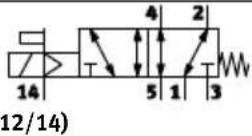 (1) (1) | MS-Piston spool valve-Single solenoid-Mechanical spring return-Reversible | ||
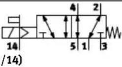 (12) (12) | MU-Polymer poppet valve-Single solenoid-Mechanical spring return-Reversible | ||
Tab. B.4 5/2-way valves

- When de-energised, 5/3-way valves assume the mid-position in by means of spring force.
- Whenever both solenoid coils on 5/3-way valves are energised simultaneously, the valve remains in the previously adopted switching position.
5/3-way valve
| Circuit symbol ID code Description/function | |||
| 14(12) |  | B | - Piston spool valve- Mid-position pressurised- Mechanical spring return- Reversible |
| 14(12) |  | E | - Piston spool valve- Mid-position exhausted- Mechanical spring return- Reversible |
| 14(12) |  | G | - Piston spool valve- Mid-position closed- Mechanical spring return- Reversible |
Tab. B.5 5/3-way valves
B.2 Pressure regulator plates
| Pressure regulator plate | |||
| Circuit symbol ID code Description/function | |||
 | PAPF2 | Pressure regulator plate for port (1)(P regulator)- Controls the operating pressure in duct (1) upstream of the direc tional valve | |
 | PCPH | Pressure regulator plate for port (2)(B regulator)- Controls the operating pressure in duct (2) downstream of the dir ectional valve | |
 | PBPG2 | Pressure regulator plate for port (4)(A regulator)- Controls the operating pressure in duct (4) downstream of the dir ectional valve | |
| Circuit symbol Description/functionID code | |||
 | PLPN | Pressure regulator plate for port (2), reversible (B regulator)– Directs operating pressure from duct (1) to ducts (3) and (5) upstream of the directional valve– Controls the pressure in duct (3) upstream of the directional valve– Directs exhaust air from duct (1) to duct (3) downstream of the directional valveNote:Combination not permitted with the following valves:– 2x 2/2-way valves (ID codes D and I)– 2x 3/2-way valves (ID codes H, K and N) | |
 | PKPM | Pressure regulator plate for port (4), reversible (A regulator)– Directs operating pressure from duct (1) to ducts (5) and (3) upstream of the directional valve– Controls the pressure in duct (5) upstream of the directional valve– Controls exhaust air from duct (1) to duct (5) downstream of the directional valveNote:Combination not permitted with the following valves:– 2x 2/2-way valves (ID codes D and I)– 2x 3/2-way valves (ID codes H, K and N) | |
Tab. B.6 Pressure regulator plates
B.3 Vertical pressure shut-off plate
| Vertical pressure shut-off plate | |||
| Circuit symbol ID code Description/function | |||
 | 4 2 12/14 PS – Makes it possible to shut down pressure in duct (1) and duct 12/14 upstream of the direction- al valve | ||
Tab. B.7 Vertical pressure shut-off plate
B.4 Vertical pressure supply plate
| Vertical supply plate | ||
| Circuit symbol ID code Description/function | ||
 | PV – Makes it 1 | possible to supply pressure separately in duct (1) upstream of the directional valve |
Tab. B.8 Vertical pressure supply plate
C Glossary
The following product-specific terms and abbreviations are used in this description:
| Term/abbreviation | Description |
| Cover plate | Plate without valve function to cover unassigned valve positions. |
| Exhaust plate Plate for ducted exhaust air with connection (3/5) | |
| Sub-base Plate with working ports connections (2) and (4) to hold valves and vertical stacking units. | |
| Cartridge Plug-in connection for attaching pneumatic lines to valve terminals. | |
| CPX modules Common term for the various modules which can be integrated into a CPX terminal | |
| CPX terminal Modular, electrical terminal | |
| Supply module Plate for (additional) supply of solenoid valves with compressed air, e.g. where there are several pressure zones | |
| Electrical interlinking Module in the sub-base with an LED and solenoid coil management | |
| End plate Furthest right plate with/without pneumatic supply ports.Furthest left plate with multi-pin plug connection and/or CPX terminal as well as bores for H-rail and wall mounting. | |
| Vertical stacking | Pneumatic components mounted between sub-base and valve. |
| I-Port | Specific interface from Festo for transmitting communication data (process data, sensor signals, control commands) and supply voltages.The I-Port communication protocol is based on the IO-Link protocol. |
| Components Collective term for pneumatic interface, multi-pin sub-base, exhaust plate, silencer, pneumatic sub-base, supply module, pressure control plate, solenoid valve and blanking plate | |
| MPA1, MPA14 and MPA2 | Size of solenoid valves: MPA1 = 10 mm, MPA14 = 14 mm and MPA2 = 20 mm |
| Multi-pin plug connection | Electrical connection for controlling the valve terminal |
| Pneumatics interface | Interface between the modular electrical peripherals of the CPX terminal and the pneumatic components |
| Pneumatic module | Module comprising pneumatic sub-base, electrical interlinking module, valve and blanking plate |
| Valve | Single solenoid valves with a magnetic coil, double solenoid impulse or mid-position valves with 2 magnetic coils and other variants |
| Valve terminal | Electromagnetic valves with a common power supply, air supply and control unit |
| Valve terminal MPAL-VI | Modular Performance Light sub-bases for a valve terminal (type 34) with multi-pin plug connection, I-Port/IO-Link interface or for CPX terminal |
| Valve position | Sub-base with electrical interlinking module to support valves, vertical stacking units or blanking plates |
| Tubing connections | Connection of pneumatic supply lines (tubing) to the valve terminals |
Tab. C.1 Terms and abbreviations
Index
A
Abbreviations, product-specific 117.....
Accessories 108.
Address assignment
– Electronics module 43.
- Example 45.
Addresses
- I-Port/IO-Link interface 16.
- Valve terminal with CPX terminal 15. . . . . . .
- Valve terminal with multi-pin connection: 14
Air humidity, permitted 97
Avoiding back pressure 52
B
Blanking plate 12, 17
- Dismantling/mounting 74
C
Cartridge 54,55
CE marking 10.
Check valve 52
Clean, Flat plate silencer 73
Common lines 52
Components
– Materials 96.
-Weights 95
Components of the valve terminal
- Labels/inscription system 36
– Pressure regulator plate 23.
- Sub-base 22.
– Supply module ..... 19
- Supply plate 37
- Valves 17
- Vertical pressure shut-off plate ..... 26
- Vertical stacking 42
- Vertical supply plate 26
Connections
-Code 53
- CPX terminal via pneumatics interface ..... 15
- Size 53
Corrosion protection 97....
Cover cap for manual override, Dismounting/mounting 66.
Cover types for multi-pin plug connection .... 15
CPX terminal
- Connection via pneumatics interface ..... 15
- Error messages on the pneumatic interface 69
Current consumption 106....
Current reduction 106
D
Display and control elements 31
- I-Port/IO-Link interface 32,70....
- Inscription system 36.
- Manual override (MO) 33
- Pressure regulator plate 34.
- Switching status indications for valves .... 33
- Vertical pressure shut-off plate .... 35
E.
.Earthing 59
Electronics module 43
- Dismantling/mounting 82
Encoder plate 38
End. plate, Dismantling/mounting ..... 79
End plate, right, Pilot air 38
Exhaust air 29,37
- Ducted 12,52,53
-.Optimisation 52
F
Faults, Fault LED / error messages 69. . . . . .
Flat cable, multi-pin plug connection ..... 14
Flat plate silencer 37
- Cleaning or replacing 73
H
H-rail, dismounting 92
|
I-Port/IO-Link interface, System overview 16....
Impairment of functions 71.
Inscription label holders, Mounting/dismounting 47....
Inscription system 36.
Intended use 9.
IP degree of protection 97.
- Cover types 15.
L
Labels 36
LED
- Position of the LEDs 33
– Switching status indication for the solenoid coil 68
Left-hand end plate
- Cover type for multi-pin plug connection ... 15
- CPX terminal with pneumatic interface 15.
- Multi-pin plug connection ..... 13
Load voltage 106, 107
Low-pressure operation 37, 58, 72
M
Manual override
- Mounting/removing the cover cap ..... 66
- Operate cover cap VMAC-L1-.... 65
- Operating the detenting manual override .. 64
- Operating the non-detenting manual override 63.
Materials 96
Medium, Requirements 50.
Modification of the valve terminal ..... 76
Multi-pin plug connection 13.
- Cover types 15.
-Flat cable 14
- Sub-D 14
- Terminal strip 14
N
MPA14 nominal flow rates 103
Nominal flow rates 102
-MPA1 102
-MPA2 104
0
Operating pressure 98
- Main and auxiliary power supply ..... 37
Operating statuses 72......
- Compressed air preparation .... 50
- Error messages 69
Operating voltage 106, 107.....
Optimisation, Flow 52. . . . . .
P
Parameterisation, Error messages on the CPX terminal 69
Pilot air 38
- Branched internally/supplied externally ... 39
- Conversion to internal/external pilot air ... 83
- Diagram 99, 100, 101
Pilot control
- Conversion to internal/external pilot air ... 83
- Diagram 99,100,101
- Pressure range 98
- Type of pilot control 57
- Connection and display components ..... 35
- Error messages 69
Power supply
- Load voltage supply for the valves ... 106, 107
- Operating voltage supply . .for.the.electronics.... 106, 107
Pressure, locking plate (vertical) 42
Pressure.regulator plate 23
- Setting 58
Pressure.zones.... 22, 40, 58, 72, 85
Product key 7
Q
QS cartridge 54, 55
R
Replace, Flat.plate silencer 73
Right.end plate.....
- Encoder plate 38
- Pilot air 38
S
Separation of pressure zones 22, 40. . . . . . . .
Solenoid coil, Current consumption 106.....
Sub-base 12, 22.....
- Dismounting/mounting 79.
Sub-D 14.
- Cover types 15.
Supply
– Main and auxiliary power. supply 37
- with pilot air 38
Supply plate, Dismounting/mounting ..... 79
Supply pressure, Internal/external pilot air .. 39
MPA1 switching times 103
MPA14 switching times 104
MPA2 switching times 105
T
Technical data 95
Temperature range, Permitted 97
Terminal strip, multi-pin plug connection .... 14
Tie rod 77
Tightening torques 96
Torques 96
Tubing connection
– Dismantling 56.
- Installation 56.
v
. Vacuum operation 37, 58, 72
Valve terminal
- Earthing the terminal 59
- With terminal CPX, Connection and display components .... 46
Supply plate 37
Valves 23....
- Dismantling/mounting 74
- ID code 17,23
- Overview 109
Vertical pressure shut-off plate 26
Vertical stacking 12
- Components 42
Pressure regulator plates 23
Vertical pressure shut-off plate ..... 26
Vertical supply plate 26
Vertical supply plate 26
W
Wall mounting, dismounting 94
Weights, Components 95
Copyright:
Festo SE & Co. KG
Ruiter Straße 82
73734 Esslingen
Germany
Phone:
+49 711 347-0
Fax:
+49 711 347-2144
Reproduction, distribution or sale of this document or communication of its contents to others without express authorization is prohibited. Offenders will be liable for damages. All rights reserved in the event that a patent, utility model or design patent is registered.
E-mail:
service_international@festo.com
Internet:
www.festo.com
- FESTO
- Danger
- Warning
- Caution
- Note
- Text designations:
- Inhaltsverzeichnis
- Safety 9.
- Product overview 11
- Mounting and installation 47
- Commissioning 61
- Diagnostics and fault clearance 68.
- MPAL-VI
- Further relevant documents
- Service
- Production period
- Safety
- Safety instructions
- Intended use
- Requirements for product use
- Technical prerequisites
- Requirements of specialised personnel
- Range of applications and certifications
- US LISTED
- Product overview
- Purpose
- Overview of components
- Electrical connection
- Multi-pin plug connection
- Connector types
- Cover types
- CPX terminal
- I-Port/IO-Link interface
- Central installation
- Decentralised installation
- Pneumatic components
- Sizes
- Valves
- Identification of the valves
- Supply module
- Right end plates
- Sub-bases
- Sub-bases with pressure zone separation
- Pressure regulator plates
- Identification of the pressure regulator plates
- Vertical pressure shut-off plate
- Vertical pressure supply plate
- Fixed flow restrictor
- Check valves
- Check valve
- Connecting components
- Pneumatic connecting components
- Electrical connecting components
- Display and operating elements
- Valve terminal
- Left end plate with I-Port/IO-Link interface
- Status LED X1
- Switching status indication of the valves
- Manual override
- Cover cap for manual override VAMC-L1-CD
- Pressure regulator plate
- Vertical pressure shut-off plate
- Pneumatic interface
- Inscription system
- Functional description
- Main and auxiliary power supply
- Exhaust air
- Vacuum or low-pressure operation
- Valves for the switching of vacuum
- Pilot air supply
- Reverse operation
- Creation of pressure zones
- Vertical stacking
- Address assignment of valve positions
- Valve terminal with multi-pin plug connection:
- Valve terminal with I-Port/IO-Link interface:
- Valve terminal with CPX terminal
- Mounting and installation
- Mounting on H-rails and walls
- Inscription label holder, mounting/dismounting
- Mounting
- Dismounting
- General installation instructions
- Compressed air preparation
- Operation with unlubricated compressed air
- Operation with lubricated compressed air
- Setting the lubricators
- Check lubricator setting
- Preventing back pressure
- Connecting the pneumatic lines
- Installing or replacing unthreaded cartridges
- Installing unthreaded cartridges
- Replacing unthreaded cartridges
- Mounting the tubing
- Cartridge 2 Locking ring
- Dismounting the tubing connection
- Connecting the compressed air supply
- Checking the type of pilot air supply
- Creating pressure zones
- Setting working pressure using the pressure regulator
- 1Adjusting screw
- Checking requirements for vacuum or low-pressure operation
- Connecting electrical cables
- Earthing a valve terminal with CPX terminal
- Adapting the address assignment of valve positions
- Commissioning
- Prior to commissioning
- Testing the valves and the valve/actuator combinations
- Commissioning variants
- Commissioning the pneumatic components with manual override
- Mounting/dismounting the optional cover caps for the manual override
- Diagnostics and fault clearance
- Switching statuses of the solenoid coils
- Fault LED on the pneumatic interface
- Status LED on the left end plate with I-Port/IO-Link interface
- Functional impairment
- Maintenance
- General safety measures
- Check oil setting (operation with lubricated compressed air)
- Cleaning or replacing flat plate silencer
- Replacing a valve or blanking plate
- Mounting valves on vertical stacking units
- Modification
- General safety measures
- Tie rod system
- Configuration
- Shortening the valve terminal
- Extending the valve terminal
- Special solutions
- Replacing or extending the sub-base, supply module, and/or replacing the right end plate
- Maximum number of sub-bases
- Dismounting
- Mounting
- Replacing electrical interlinking modules
- Damage to the product due to incorrect handling.
- Conversion to ducted or unducted exhaust air
- Converting power supply modules to unducted exhaust air
- Converting supply modules to ducted exhaust air
- Conversion with right end plate with supply ports
- Conversion to internal or external pilot air supply
- Conversion with right end plate without supply ports
- Conversion with right end plate with supply ports
- Conversion of valve terminal to different pressure zones
- Conversion of left end plate from IP40 to IP65/67 cover
- Dismounting
- Mounting
- Conversion of output direction of multi-pin plug connecting cable
- Preparatory steps
- Conversion to lateral cable output
- Conversion to straight cable output
- Conversion of left end plate between multi-pin or I-Port/IO-Link interface and CPX port
- Dismounting
- Mounting
- Replacing pneumatic interface
- Dismounting
- Mounting
- Dismounting
- General instructions for dismounting
- Dismounting from H-rails
- Variant
- Valve terminal with CPX terminal
- Dismounting from walls
- A Technical appendix
- A.1 Technical data
- A.1.2 Operating and environmental conditions
- A.1.3 Pneumatics
- A.1.4 Electrical
- A.2 Accessories
- B Extended component description
- B.1 Valves
- B.2 Pressure regulator plates
- B.3 Vertical pressure shut-off plate
- B.4 Vertical pressure supply plate
- C Glossary
- Index
- A
- B
- C
- D
- F
- H
- |
- L
- M
- N
- 0
- P
- Q
- R
- S
- T
- v
- W
Brand : Festo
Model : MPAL-VI-DE
Category : Compressor