
PR750ELCD - Inverter CyberPower - Free user manual and instructions
Find the device manual for free PR750ELCD CyberPower in PDF.


| Product Type | Uninterruptible Power Supply (UPS) |
| Topology | Line-interactive |
| VA Rating | 750 VA |
| Wattage Rating | 450 W |
| Input Voltage | 230 V AC |
| Input Frequency | 50/60 Hz |
| Output Waveform | Simulated sine wave |
| Number of Outlets | 8 (5 battery backup + 3 surge only) |
| Data Line Protection | RJ11/RJ45 (Telephone/Network) |
| Interface Port | USB |
| Battery Type | Sealed lead-acid (12 V, 7 Ah) |
| Battery Replacement | User-replaceable, hot-swappable |
| Runtime at Half Load | Approximately 12 minutes |
| Runtime at Full Load | Approximately 3 minutes |
| Dimensions (W x H x D) | 300 x 152 x 386 mm (11.8 x 6.0 x 15.2 in) |
| Net Weight | 8.4 kg (18.5 lbs) |
| Operating Temperature | 0°C to 40°C (32°F to 104°F) |
| Operating Humidity | 0% to 95% non-condensing |
| Audible Noise | < 40 dBA |
| Management Software | PowerPanel Personal (included) |
| Warranty | 2 years (limited) |
| Certifications | CE, TUV, GS |
Frequently Asked Questions - PR750ELCD CyberPower
User questions about PR750ELCD CyberPower
0 question about this device. Answer the ones you know or ask your own.
Ask a new question about this device
Download the instructions for your Inverter in PDF format for free! Find your manual PR750ELCD - CyberPower and take your electronic device back in hand. On this page are published all the documents necessary for the use of your device. PR750ELCD by CyberPower.
USER MANUAL PR750ELCD CyberPower
PR750ELCD User's Manual
IMPORTANT SAFETY INSTRUCTIONS
This manual contains important safety instructions. Please read and follow all instructions carefully during installation and operation of the unit. Read this manual thoroughly before attempting to unpack, install, or operate your UPS.
CAUTION! The UPS must be connected to a grounded AC power outlet with fuse or circuit breaker protection.
DO NOT plug the UPS into an outlet that is not grounded. If you need to de-energize this equipment, turn off and unplug the UPS.
CAUTION! DO NOT USE FOR MEDICAL OR LIFE SUPPORT EQUIPMENT! CyberPower Systems does not sell products for life support or medical applications. DO NOT use in any circumstance that would affect the operation and safety of life support equipment, medical applications, or patient care.
CAUTION! Hazardous live parts inside can be energized by the battery even when the AC input power is disconnected.
CAUTION! To prevent the risk of fire or electric shock, install in a temperature and humidity controlled indoor area, free of conductive contaminants. (Please see specifications for acceptable temperature and humidity range).
CAUTION! To reduce the risk of electric shock, do not remove the cover, except to service the battery. There are no user serviceable parts inside, except for the battery.
CAUTION! To avoid electrical shock, turn off the unit and unplug it from the AC power source before servicing the battery or installing a computer component.
CAUTION! DO NOT USE WITH OR NEAR AQUARIUMS! To reduce the risk of fire, do not use with or near aquariums. Condensation from the aquarium can come in contact with metal electrical contacts and cause the machine to short out.
UNPACKING
The box should contain the following:
(1) UPS Unit x 1; (2) Emergency Power Off Cable (gray) x 1; (3) Serial Cable x 1;
(4) USB Cable x 1 (5) User Manual x 1; (6) Management software Disk x 1;
(7) Function Setup Guide x 1; (8) IEC to IEC Power cord x1
OVERVIEW
The PR750ELCD provides automatic voltage regulation for inconsistent utility power. The PR750ELCD features 405 Joules of surge protection, and provides battery backup during power outages. The PR750ELCD ensures consistent power to your computer system and its included software will automatically save your open files and shut down your computer system during a utility power loss.
HOW TO DETERMINE THE POWER REQUIREMENTS OF YOUR
EQUIPMENT
- Make sure that the total Volt-Amp (VA) requirements of your computer, monitor, and peripheral equipment does not exceed 750VA.
- Ensure that the equipment plugged into the battery power-supplied/surge outlets does not exceed the UPS unit's rated capacity (750VA/675W for PR750ELCD). If the rated unit capacities are exceeded, an overload condition may occur and cause the UPS unit to shut down or the circuit breaker to trip.
DESCRIPTION
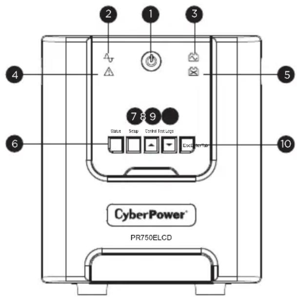

1. Power Switch / Power On Indicator
Used as the master on/off switch for equipment connected to the battery power supplied outlets.
2. Online Indicator
This LED is illuminated when the utility power is normal and the UPS outlets are providing power, free of surges and spikes.
3. On Battery Indicator
During a severe brownout or blackout, this LED is illuminated and an alarm sounds (two short beeps followed by a pause) to indicate the UPS is operating from its internal batteries.
4. Fault
This LED is illuminated if there is a problem with the UPS.
5. Replace Battery Indicator
This LED is illuminated to remind users to replace the battery.
6. Tab / Status Button
For UPS status information, press the button for 1 second. For additional information including the use of the button as a Tab, please refer to the Function Setup Guide.
7. Enter / Setup Button
Press the Setup button for 1 second to enter setup menu and then select the functions for configuration. For more information about the Setup/Enter button, please refer to the Function Setup Guide.
8. Up / Control Button
Press the Control button for 1 second to enter control menu and then select the functions for configuration. This button is also used to scroll up. For more information about the Control/Up button, please refer to the Function Setup Guide.
9. Down / Test Button
Press the Test switch for 1 second to enter test menu and then select the functions for configuration. This button is also used to scroll down. For more information about the Test/Down button, please refer to the Function Setup Guide.
UNPACKING
10. Esc / Logs Button
Press the Logs button for 1 second to view the events or logs that have been recorded. This button is also used to exit a menu. For more information about Logs/Esc button, please refer to the Function Setup Guide.
11. Battery and Surge Protected Outlets
The unit has six battery powered/surge suppression outlets for connected equipment to ensure temporary uninterrupted operation of your equipment during a power failure. (DO NOT plug a laser printer, paper shredder, copier, space heater, vacuum, sump pump or other large electrical devices into the “Battery and Surge Protected Outlets”. The power demands of these devices may overload and damage the unit.)
12. Serial / USB Ports to PC
The Serial and USB ports allow connection and communication between the computer and the UPS unit. Note: Only one port can be used at a time.
13. EPO Port
Use the provided gray EPO cable to connect to a provided EPO contact switch. Follow the appropriate circuit diagram to the right to wire the cable to your EPO configuration. The EPO remote switch is a switch installed in an outside area, connected to the unit via the Emergency Power Off cable. In case of an emergency, it can be used to immediately cut-off power from the UPS.
OPTION 1: USER SUPPLIED NORMALLY CLOSED SWITCH

OPTION 2: USER SUPPLIED NORMALLY OPEN SWITCH

14. SNMP/HTTP Network Slot
Remove the cover panel to install an optional RMCARD to remotely monitor and manage your UPS over a network.
15. Circuit Breaker
Located on the back of the UPS, the circuit breaker provides overload and fault protection.
16. AC Input
Connect the AC power cord to a properly wired and grounded outlet.
- Your new UPS may be used immediately upon receipt. However, recharging the battery for at least 8 hours is recommended to ensure that the battery's maximum charge capacity is achieved. Charge loss may occur during shipping and storage. To recharge the battery, simply leave the unit plugged into an AC outlet. The unit will charge in both the on and off position.
Note: This UPS is designed with a safety feature to keep the system from being turned on during shipment. The first time you turn the UPS on, you will need to have it connected to AC power or it will not power up.
- If you will use the software, connect the USB cable to the USB port on the UPS.
- With the UPS unit off and unplugged, connect the computer, monitor, and any externally powered data storage device (Zip drive, Jazz drive, Tape drive, etc. into the battery power supplied outlets. DO NOT plug a laser printer, copier, space heater, vacuum, paper shredder or other large electrical device into the battery power supplied outlets. The power demands of these devices will overload and possibly damage the unit.
- Plug the UPS into a 2 pole, 3 wire grounded receptacle (wall outlet). Make sure the wall branch outlet is protected by a fuse or circuit breaker and does not service equipment with large electrical demands (e.g. air conditioner, refrigerator, copier, etc. Avoid using extension cords.
- Depress the power switch to turn the unit on. The power on indicator light will illuminate and the unit will "beep".
- If an overload is detected, an audible alarm will sound and the unit will emit one long beep. To correct this, turn the UPS off and unplug at least one piece of equipment from the battery power supplied outlets. Wait 10 seconds. Make sure the circuit breaker is depressed and then turn the UPS on.
- Your UPS is equipped with an auto-charge feature. When the UPS is plugged into an AC outlet, the battery will automatically recharge.
- To maintain optimal battery charge, leave the UPS plugged into an AC outlet at all times.
- To store your UPS for an extended period, cover it and store with the battery fully charged. Recharge the battery every three months to ensure battery life.
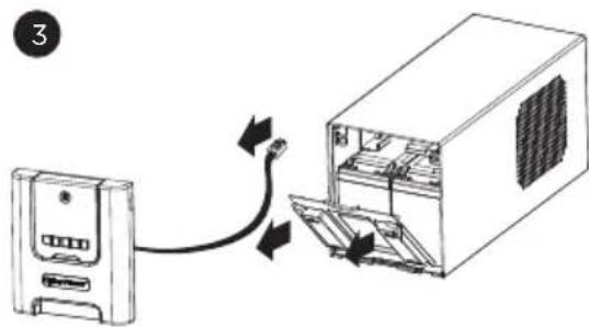
- The LCD module is wall-mountable for extended distance control. Follow the steps below for installation procedure.
a. Remove the LCD module from the front panel.
b. Hang the LCD module on the wall.
c. Replacing the LCD on the UPS - To place the LCD back on the UPS, roll up the LCD cable, return it to the space between the front panel & battery cover, and replace the LCD.

CyberPower's Green Commitment
CyberPower is dedicated to the development of green products, and has adopted Green practices throughout its business, including: membership in Climate Savers Computing Initiative (CSCI), accordance with the Restriction on Hazardous Substances (RoHS), Waste Electrical and Electronic Equipment (WEEE) protocols, as well as ISO 14001 and IECQ QC080000. CyberPower pledges to provide the advanced energy solution for the environment and become a leading eco-friendly organization in the UPS industry.

Reduce Energy Cost with GreenPower UPS TM Technology
CyberPower's goal is not only to provide eco-friendly products but also to bring the best value for consumers. The advanced energy-saving design improves the operating efficiency and eliminates waste energy consumption. As a result, consumers will enjoy significant energy cost savings with the adoption of GreenPower UPS™ technology.
BATTERY REPLACEMENT
The UPS features hot-swappable function for uninterrupted operation during battery replacement. This feature allows users to safely replace batteries without having to shut down the UPS or connected equipment, ensuring UPS's maximum power availability.
CAUTION! Read and follow the IMPORTANT SAFETY INSTRUCTIONS before servicing the battery.
CAUTION: DO NOT REPLACE BATTERIES WHILE THE UPS IS IN BATTERY MODE.
CAUTION: WHEN THE BATTERY PACK IS DISCONNECTED, THE LOADS CONNECTED TO THE UPS ARE NOT PROTECTED FROM POWER FAILURE.
CAUTION: Maintenance work must be carried out by a qualified technician who is familiar with batteries and the necessary safety regulations. Do not allow unauthorized personnel to handle the batteries.
CAUTION! Use only the specified type of battery. See your dealer for replacement batteries.
CAUTION! The battery may present the risk of electrical shock. Do not dispose of batteries in a fire, as they may explode. Follow all local ordinances regarding proper disposal of batteries.
CAUTION! Do not open or mutilate the batteries. Released electrolyte is harmful to the skin and eyes and may be toxic.
CAUTION! A battery can present a high risk of short circuit current and electrical shock. Take the following precautions before replacing the battery:
- Remove all watches, rings or other metal objects.
- Only use tools with insulated handles.
- DO NOT lay tools or other metal parts on top of battery or any battery terminals.
-
Wear rubber gloves and boots.
-
Determine if the battery is inadvertently grounded. If inadvertently grounded, remove source of ground. CONTACT WITH A GROUNDED BATTERY CAN RESULT IN ELECTRICAL SHOCK! The likelihood of such shock will be reduced if such grounds are removed during installation and maintenance (applicable to a UPS and a remote battery supply not having a grounded circuit)
INSTALLING YOUR UPS SYSTEM
BATTERY REPLACEMENT PROCEDURE:
- Remove the front panel of the UPS.
- Pull out both round knobs and remove the battery compartment cover completely off of the unit.
- Remove the batteries from the compartment.
- Disconnect the battery wires from the batteries.
- Install the replacement batteries by connecting the wire bundle (composed of one red wire and one black wire) to the connector from the battery pack.
- Put the batteries back into the compartment.
- Re-install the battery compartment cover and push both round knobs back into place.
- Remove the LCD module before putting the front panel back on the UPS.
- Replacing the LCD on the UPS - To place the LCD back on the UPS, roll up the LCD cable, return it to the space between the front panel & battery cover, and replace the LCD.
- Recharge the UPS for 8-16 hours to fully charge the battery.
REMINDER: Batteries are considered HAZARDOUS WASTE and must be disposed of properly. Almost any retailer that sells lead-acid batteries collects used batteries for recycling.




DEFINITIONS FOR ILLUMINATED LCD INDICATORS
| Status Menu | |
| Operation ModeLoad PowerLoad VALoad AmpsLoad EnergyEstimated Runtime | Battery InformationInputOutputLast Self TestDate & Time |
| Setup Menu | |
| Setup WizardLanguageUtility PowerMIN O/P VoltageMAX O/P VoltageLCD Auto SleepCycling DisplayAudible AlarmTemporarily MuteSensitivityCharge ModeLow Battery Warning | Auto Self TestDate & TimeBattery Change DateFirmware UpdatePower Meter ResetBack to DefaultDelay Turn OnDelay Turn OffReboot DurationMinimum Restore CapacityUptime on BatteryReserve Runtime |
| Control Menu | |
| UPS On/Off | |
| Control Menu | |
| Self TestAlarm Test | Battery Calibration |
| Logs Menu | |
| Transfer Event X1-X10Fault Event F1-F10Model NameLast Battery Change | Next Battery ChangeUPS Firmware VersionLCD Firmware VersionSerial Number |
For more information about functions setup, please refer to the Function Setup Guide.
TECHNICAL SPECIFICATIONS
| Model PR750ELCD | |
| Capacity (VA) 750VA/675W | |
| Input | |
| Frequency Range 47-63Hz (Auto Sensing) | |
| AVR Function Yes | |
| Output | |
| On Battery Output Voltage 230 | Vac +/-5% |
| On Battery Output Frequency 50/60Hz +/-1% | |
| Overload Protection | On Utility: Circuit Breaker & Internal Current Protection On Battery: Internal Current Limiting |
| Surge Protection | |
| Lightning / Surge Protection Yes | |
| Operating Temperature +32°F to 104°F (0°C to 40°C) | |
| Physical | |
| Total # of UPS outlets IEC x 6 | |
| Maximum Dimensions(LxWxH) | 349 x 138 x 162 mm |
| Weight (kg) 12.3kg | |
| Battery | |
| Battery Sealed Maintenance Free Lead Acid Battery | |
| Typical Recharge Time 8 hours | |
| Charging Current(Max.) 0.6A | |
| User Replaceable Yes | |
| Status Indicators | |
| Indicators | Power On, LCD Display, Online, On Battery, Fault, Replace Battery |
| Audible Alarms | On Battery, Low Battery, Overload |
| Communication | |
| PowerPanel® Personal Edition Software | Windows 7/Vista/XP/2000/Server 2003, Linux |
| Management | |
| Self -Test | Yes |
| Auto-Charger | Yes |
| Auto-Restart | Yes |
| USB interface | Yes |
| Expansion Port | Yes |
| EPO Port | Yes |
TROUBLESHOOTING
| Problem Possible | Cause Solution | |
| Circuit breaker button is projecting from the back of the unit. | Circuit breaker has tripped due to an overload. | Turn the UPS off and unplug at least one piece of equipment. Wait 10 seconds, reset the circuit breaker by depressing the button, and then turn the UPS on. |
| The UPS does not perform expected runtime. | Battery not fully charged. | Recharge the battery by leaving the UPS plugged in. |
| Battery is slightly worn out. | Contact CyberPower Systems about replacement batteries at support@cpsww.eu | |
| The UPS will not turn on. | The on/off switch is designed to prevent damage by rapidly turning it off and on. | Turn the UPS off. Wait 10 seconds and then turn the UPS on. |
| The battery is worn out. | Contact CyberPower Systems about replacement batteries at support@cpsww.eu | |
| Mechanical problem. | Contact CyberPower Systems at support@cpsww.eu | |
| PowerPanel® Business Edition is inactive. | The USB cable is not connected. | Connect the USB cable to the UPS unit and an open serial port on the back of the computer. You must use the cable that came with the unit. |
| The unit is not providing battery power. | Shutdown your computer and turn the UPS off. Wait 10 seconds and turn the UPS back on. This should reset the unit. | |
| The fault LED is illuminated. | Overload | Remove excessive load and restart the UPS. |
| Output Short | Contact CyberPower Systems at support@cpsww.eu | |
| Battery Overcharge | Contact CyberPower Systems at support@cpsww.eu | |
| Over Temperature | Contact CyberPower Systems at support@cpsww.eu |
Additional troubleshooting information can be found at www.cpsww.eu
For more information, visit www.cpsww.eu or contact
Cyber Power Systems, Inc.
E-MAIL: sales@cpsww.eu
All rights reserved. Reproduction without permission is prohibited.
WIE SIE DEN STROMBEDARF IHRER GERÄTE ERMITTELN
CyberPower's Green-IT Engagement
DEFINITIONS FOR ILLUMINATED LCD INDICATORS
Cyber Power Systems, Inc.
E-MAIL: sales@cpsww.eu
- PR750ELCD USER'S MANUAL
- IMPORTANT SAFETY INSTRUCTIONS
- UNPACKING
- OVERVIEW
- HOW TO DETERMINE THE POWER REQUIREMENTS OF YOUR
- EQUIPMENT
- DESCRIPTION
- POWER SWITCH / POWER ON INDICATOR
- ONLINE INDICATOR
- ON BATTERY INDICATOR
- FAULT
- REPLACE BATTERY INDICATOR
- TAB / STATUS BUTTON
- ENTER / SETUP BUTTON
- UP / CONTROL BUTTON
- DOWN / TEST BUTTON
- ESC / LOGS BUTTON
- BATTERY AND SURGE PROTECTED OUTLETS
- SERIAL / USB PORTS TO PC
- EPO PORT
- SNMP/HTTP NETWORK SLOT
- CIRCUIT BREAKER
- AC INPUT
- CYBERPOWER'S GREEN COMMITMENT
- REDUCE ENERGY COST WITH GREENPOWER UPS TM TECHNOLOGY
- BATTERY REPLACEMENT
- INSTALLING YOUR UPS SYSTEM
- BATTERY REPLACEMENT PROCEDURE
- DEFINITIONS FOR ILLUMINATED LCD INDICATORS
- TECHNICAL SPECIFICATIONS
- TROUBLESHOOTING
- WIE SIE DEN STROMBEDARF IHRER GERÄTE ERMITTELN
- CYBERPOWER'S GREEN-IT ENGAGEMENT
- CYBER POWER SYSTEMS, INC
Brand : CyberPower
Model : PR750ELCD
Category : Inverter