
CPS600E-DE - Charger CyberPower - Free user manual and instructions
Find the device manual for free CPS600E-DE CyberPower in PDF.


| Product Type | Emergency Power System (EPS) / Line-Interactive UPS |
| Model | CPS600E-DE |
| Brand | CyberPower |
| Capacity (VA / Watts) | 600VA / 420W |
| Technology | Automatic Voltage Regulation (AVR) – Single Boost & Single Buck |
| Input Voltage Range | 170Vac – 270Vac |
| Input Frequency Range | 45 – 65 Hz (auto sensing) |
| Output Voltage (On Battery) | 230Vac ±5% (pure sine wave up to 40% load, trapezoidal above) |
| Output Voltage (Configurable) | 220V or 230V |
| Output Frequency (On Battery) | 50/60 Hz ±1% |
| Transfer Time | <10 ms typical |
| Output Receptacles | 1 x Schuko type |
| External Battery | 12V, Sealed Lead Acid, recommended 100Ah, quantity 1 |
| Battery Protection | DC fuse |
| Display | Multifunction LCD with backlight |
| Audible Alarms | On Battery, Low Battery, Overload |
| Operating Temperature | 0°C to 40°C (32°F to 104°F) |
| Operating Humidity | 0 – 90% non-condensing |
| Dimensions (L x W x H) | 240 x 162 x 90 mm |
| Weight | 4.1 kg |
| Mounting | Horizontal or wall-mount |
| Input Fuse | 6.3A / 250V |
| DC Fuse Included | 2 pieces (spare) |
| Battery Cable | 10AWG, 4 ft (1.2 m) – positive and negative |
| Safety Certifications | CE, SONCAP, EN62040-1-1 |
| EMC Classification | IEC/EN 62040-2 Category C2 |
Frequently Asked Questions - CPS600E-DE CyberPower
User questions about CPS600E-DE CyberPower
0 question about this device. Answer the ones you know or ask your own.
Ask a new question about this device
Download the instructions for your Charger in PDF format for free! Find your manual CPS600E-DE - CyberPower and take your electronic device back in hand. On this page are published all the documents necessary for the use of your device. CPS600E-DE by CyberPower.
USER MANUAL CPS600E-DE CyberPower
Reliability. Quality. Value.
natural_image
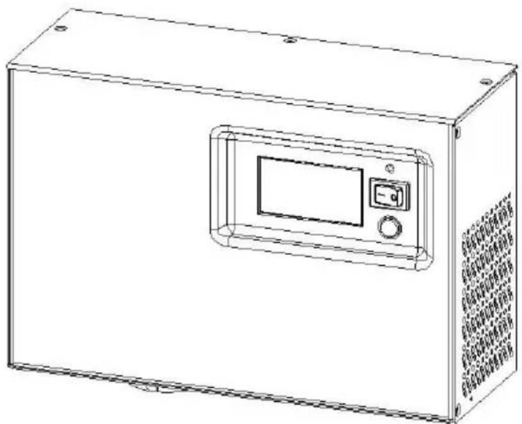
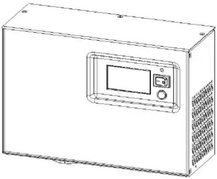
Line drawing of a rectangular electronic device with a central control panel and ventilation grilles (no text or symbols)CPS600E-DE
User's Manual
SAFETY AND EMC INSTRUCTIONS
This manual contains important safety instructions. Please read and follow all instructions carefully during installation and operation of the unit. Read this manual thoroughly before attempting to unpack, install, or operate your Emergency Power System (EPS).
CAUTION! To prevent the risk of fire or electric shock, install in a temperature and humidity controlled indoor area free of conductive contaminants. (Please see specifications for acceptable temperature and humidity range).
CAUTION! To reduce the risk of electric shock, do not remove the cover, except to service the battery. There are no serviceable parts inside, except for the battery.
CAUTION! EPS must be connected to an AC power outlet with circuit breaker protection. Do not plug into an outlet that is not grounded. If you need to de-energize this equipment, turn off and unplug the unit.
CAUTION! To avoid electrical shock, turn off the unit and unplug it from the AC power source before servicing EPS, replacing the external battery or installing equipment.
CAUTION! To reduce the risk of fire, only connect the EPS to a circuit with 10 amperes maximum branch circuit over-current protection in accordance with the CE requirement.
CAUTION! The building wiring socket outlet (shockproof socket outlet) must be easily accessible and close to the EPS.
CAUTION! Please use only VDE-tested, CE-marked mains cable (e.g. the mains cable of your equipment) to connect the EPS to the building wiring socket outlet (shockproof socket outlet).
CAUTION! Please use only VDE-tested, CE-marked power cables to connect the loads to the EPS.
CAUTION! When installing the equipment, ensure that the sum of the leakage current of the EPS and the connected equipment does not exceed 3.5mA.
CAUTION! Do not disconnect the mains cable on the EPS or the building wiring socket outlet (shockproof socket outlet) during operations since this would remove the protective ground of the EPS and of all connected loads.
CAUTION! This is a class A product. In a domestic environment this product may cause radio interference in which case the user may be required to take adequate measures.
DO NOT USE FOR MEDICAL OR LIFE SUPPORT EQUIPMENT!
DO NOT use in any circumstance that would affect operation and safety of any life support equipment, any medical applications or patient care.
DO NOT USE WITH OR NEAR AQUARIUMS! To reduce the risk of fire or electric shock, do not use with or near an aquarium. Condensation from the aquarium can cause the unit to short out.
DO NOT INSTALL THE EPS WHERE IT WOULD BE EXPOSED TO DIRECT SUNLIGHT OR NEAR HEAT!
DO NOT BLOCK OFF VENTILATION OPENINGS IN THE EPS'S HOUSING!
SAFETY:
EN62040-1-1
EMI:
Conducted Emission: IEC/EN 62040-2...Category C2
Radiated Emission: IEC/EN 62040-2.....Category C2
Harmonic Current: IEC/EN61000-3-2
Voltage Fluctuations and Flicker: IEC/EN61000-3-3
EMS:
IEC/EN61000-4-2(ESD)
IEC/EN61000-4-3(RS)
IEC/EN61000-4-4(EFT)
IEC/EN61000-4-5(lightning surge)
IEC/EN61000-2-2 (Immunity to low frequency signals)
INSTALLING YOUR EPS
UNPACKING
Inspect the EPS upon receipt. The box should contain the following:
(1) EPS Unit x 1; (2) User Manual x 1; (3) Input Power Cord x 1; (4) DC Fuse x 2
AUTOMATIC VOLTAGE REGULATOR
Utility power is inconsistent. The EPS increases low voltage to computer safe 230 volts. The EPS automatically provides battery backup (External battery connection required) if the voltage drops below 170 volts or exceeds 270 volts.
HARDWARE INSTALLATION GUIDE
- Your new EPS may be used immediately upon receipt. However, recharging the external battery for at least 8 hours is recommended to ensure that the battery's maximum charge capacity is achieved. To recharge the external battery, simply leave the unit plugged into an AC outlet when EPS is ON.
- DO NOT use with medical or life support equipment. DO NOT use with or near aquariums as condensation may cause the unit to short out.
- After connecting the hard wires, plug the EPS into a 2 pole, 3 wire grounded receptacle (wall outlet). Make sure the wall branch outlet is protected by a fuse or circuit breaker and does not service equipment with large electrical demands (e.g. air conditioner, copier, etc...). The warranty prohibits the use of extension cords, outlet strips, and surge strips.
- Press the power switch to turn the unit on. The power on indicator light will illuminate and the unit will beep once.
- If an overload is detected, an audible alarm will sound and the unit will emit one long beep. To correct this, turn the EPS off and unplug the equipment from the AC outlet. Ensure that the equipment plugged into the outlet does not exceed the UPS unit's rated capacity (600VA/420W for CPS600E-DE). If the rated capacities of the unit are exceeded, an overload condition may occur and cause the UPS unit to shut down or the input fuse to blow. For more information, refer to the "Troubleshooting" section.
- To maintain optimum battery charge performance, make the EPS plugged into an AC outlet at all times.
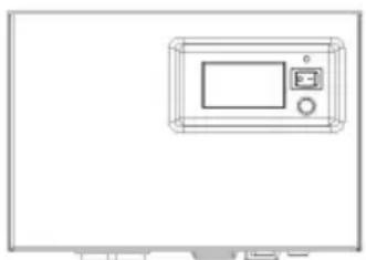
- The UPS is designed for horizontal or wall-mount use only. To ensure safety, please follow the placement directions as shown below.
natural_image
Line drawing of a microwave oven with control panel and display (no text or symbols)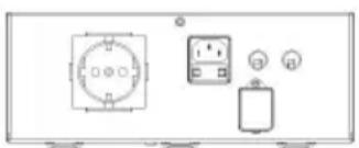
natural_image
Diagram of a front-mounted electronic device with two circular components and three connected indicators (no text or symbols)BASIC OPERATION
DESCRIPTION
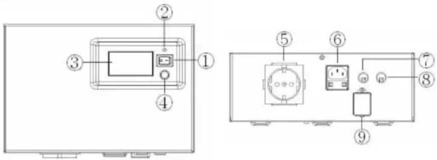
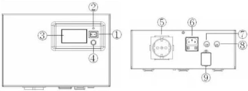
1. Power Switch
Used as the master on/off switch for equipment connected to the AC outlet.
2. Power On Indicator
This LED is above the power switch. It illuminates when the utility condition is normal and the AC outlet is providing power, free of surges and spikes.
3. Multifunction LCD Readout
High resolution and intelligent LCD display shows all the EPS information with icons and messages. For more information please check the DEFINITIONS FOR ILLUMINATED LCD INDICATORS section.
4. LCD Display Toggle / Selected Switch
Users can monitor EPS status and set up functions using the toggle. The buzzer on/off can also be controlled by the toggle switch. Please refer to "EPS Status Inquiry and Functions Setup" section for more details.
5. AC Outlet
The unit has one Schuko type outlet for connected equipment to ensure temporary uninterrupted operation during a power failure. Max. Output is 6.3A; Max. Output wattage is 420W.
Note! Maximum cord length is 10 meters and the cable O.D. must be 14AWG or greater.
6. AC Inlet
Connect to utility power through the input power cord.
Note : The O.D. of the distribution cables must be 1.0mm or greater.
Input Fuse
The fuse provides optimal overload protection.
Note : The Input Fuse is 6.3A/250V.
7. Black Battery Cable (Negative (-))
Connect black (negative (-)) battery cable to the black (negative (-)) connector on the external battery.
Note: The Battery cable is 10AWG / 4 feet.
8. Red Battery Cable (Positive (+))
Connect red (positive (+)) battery cable to the red (positive (+)) connector on the external battery.
Note: The Battery cable is 10AWG / 4 feet.
9. DC Fuse
The fuse provides optimal overload protection for battery mode operation.
REPLACING THE BATTERY
CAUTION! Read and follow the IMPORTANT SAFETY INSTRUCTIONS before servicing the battery. Battery service should only be done by qualified professionals.
CAUTION! Use only the specified type and number of external batteries. Please see the technical specifications for replacement batteries.
CAUTION! The battery may present a risk of electrical shock. Do not dispose of battery in a fire as it may explode. Follow all local ordinances regarding proper disposal of batteries. Lead-acid batteries should be recycled.
CAUTION! Do not open or mutilate the batteries. Released electrolyte is harmful to skin and eyes and may be toxic.
CAUTION! A battery can present a high risk of short circuit current and electrical shock.
Take the following precautions before replacing the battery:
- Remove all watches, rings or other metal objects.
- Only use tools with insulated handles.
- Do not lay tools or metal parts on top of battery or any terminals.
-
Wear rubber gloves and boots.
-
Determine if the external battery is inadvertently grounded. If grounded, remove the source of ground. CONTACT WITH GROUNDED BATTERY CAN RESULT IN ELECTRICAL SHOCK!
DEFINITIONS FOR ILLUMINATED LCD INDICATORS
The LCD Display indicates a variety of EPS operational conditions. All descriptions apply when the EPS is plugged into an AC outlet and turned on or when the EPS is on battery.
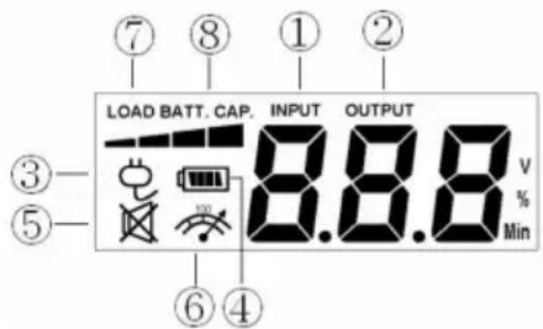
- INPUT VOLTAGE Meter: This meter measures the AC voltage that the EPS is receiving from the utility wall outlet. The EPS is designed, through the use of automatic voltage regulation, to continuously supply connected equipment with stable, 230 output voltage. In the event of a complete power loss, severe brownout or over-voltage the EPS will rely on its external battery to supply consistent 230 output voltage. The Input Voltage Meter can be used as a diagnostic tool to identify poor quality input power.
- OUTPUT VOLTAGE Meter: This meter measures, the AC voltage that the EPS is providing to the computer. It displays normal line mode, AVR mode, and battery backup mode.
- NORMAL MODE Icon: This icon will illuminate when the EPS is working under normal conditions.
-
ON BAT (On Battery) Icon: When a severe brownout or blackout, this icon appearing and an alarm (two short beeps) activated indicate that the EPS is working via its batteries. Once the batteries are running out of power, for a period of time, an alarm (two short beeps) will appear continuously. If this occurs, it is recommended that save your files and turn off your equipment manually as soon as possible.
-
SILENT MODE Icon: This icon appearing indicates that the buzzer does not beep in the silent mode until the low battery capacity.
-
OVER LOAD Icon: This icon appearing and an alarm activated indicate that the overload condition. To relieve the overload, unplug your equipment from the EPS outlets until the icon disappears and the alarm stops being activated.
-
LOAD CAPACITY: Load CAPACITY is also shown on the bar chart; equal 25% load capacity for each segment.
-
BATTERY VOLTAGE: BATT. VOLTAGE indicates the voltage of battery.
EPS STATUS INQUIRY AND FUNCTIONS SETUP
GENERAL MODE
a. Press the "Display" button to check the status of the EPS
| Items Unit | |
| Input Voltage V | |
| Output Voltage V | |
| Load Capacity % | |
| Battery Voltage V |
b. Press and hold the Display toggle for 4 seconds.
- If the machine is in the Battery Mode, it enters the silent mode. Press again for 4 seconds and it will return to normal (buzzer) mode.
- If the machine is in the Line Mode, it proceeds to Self Test.
c. If the Display toggle remains untouched for over 30 seconds, the LCD backlight will turn off automatically.
SET-UP MODE
Step 1: Hold the Display toggle for 10 seconds to enter the EPS set-up Mode. LCD icon 1, 2 lights indicate Set-Up Mode.
Step 2: By pressing the Display toggle, users can switch between setup functions. User configurable functions are as follows:
a. Delay Time: The time delay between switching from Battery Mode to Line Mode. There are 9 different settings. The default setting is 0.0 minute.
Function description: The machine will switch from Battery Mode to Line Mode after the AC power transmission reaches stability within the preset delay time.
b. Charging Current: The function adjusts the battery charging current according to the capacity of the connected batteries. It can be configured for 25, 50, 75, and 100%. The default setting is 75%. 100% indicates that charging current is about 10Amps.
c. Nominal Output Voltage: Configures the correct electricity/voltage supplied in the area/country where the EPS will be used. 220V and 230V may be selected. The system default setting is 230V.
Function description: AVR Dynamic Voltage Compensation works automatically based on the system voltage settings.
d. Static Frequency Tolerance: There are 6 settings (1,2,4,6,8,10%), and the default setting is +/-6%.
Function description: The settings may be adjusted to the quality of the electricity in use.
e. Slew Rate: Also called Dynamic Frequency Tolerance. There are 5 different settings (0.25, 0.5, 1, 2, 4 Hz/Sec). The default value is 4Hz/sec.
Function description: "Slew Rate" indicates the tolerance of a device in accepting frequency variances. The lower "Slew Rate" results in less tolerance but better protection for the connected loads.
f. Low Battery Shutdown Voltage: This function adjusts the EPS shutdown point according to the battery voltage. The default setting is 10.8V (with load).
g. Mode Select: The standard mode (setting: 2) and the robust mode (setting: 1) are provided to select. Using the generators is suggested to select the robust mode (setting: 1), and using the computers is suggested to select the standard mode (setting: 2). The system default setting is standard mode (setting: 2).
The settable items are sorted by unit as in the following table:
| Items Unit Icon Lit n | ||
| Delay Time Min ON BAT | ||
| Charging Current % ON BAT | ||
| Nominal Output Voltage V NORMAL MODE | ||
| Static Frequency Tolerance | % NORMAL MODE | |
| Slew Rate | % None | |
| Low Battery Shutdown Voltage | V ON BAT | |
| Mode Select | None | None |
Step 3: Press and hold the toggle for 4 seconds. When the icons blink, the value of each item can be changed by slightly pressing the toggle.
Step 4: To save the value and return to general mode, press and hold the toggle for 4 seconds.
Note: If the machine is left idle for over 30 seconds during setup, it will turn off the backlight and return to general mode automatically.
Note: If user wants to return to general mode without saving changes, there are two methods:
- Wait for the backlight to turn off
- Press and hold the "Display" toggle for 10 seconds
FAULT WARNING DISPLAY AND ALARM
- Overheat Protection: The EPS output will be interrupted. After 30 seconds, the machine shuts down and the LCD display output voltage is zero.
- Over-Load Protection : The EPS output will be interrupted. After 30 seconds, the machine shuts down and Over Load Icon lights on the LCD display.
- Battery Missing : You should hear a long beep and Battery Indicator flashes
- Low Battery Protection: The EPS output will be interrupted. After 30 seconds, the machine shuts down and the LCD display output voltage is zero.
- The following table shows each corresponding warning message on the LCD display and the alarm reacts during the machine shut down:
| LCD Warning Display | Alarm | Condition Solution | |
| Over Load Icon Constant tone | Over Load Output-Off - Load exceed the rating of EPS. | Check total load to confirm the rating of EPS. | |
| Zero Output Voltage Constant tone | High Temperature Output-Off | Check fans function and air vent clearances. | |
| Low Battery Output-Off -- Insufficient battery capacity. | Recharge the battery. | ||
| Over Charge or AVR Error-- In Line Mode, battery is overcharged or AVR is faulty. | Inform service agents. | ||
| Short Output-Off -- Output Short Circuit Protection | Check the EPS output to see if there is a short circuit. | ||
| Can Not Start Up None | Line Input/ Output Error Output-Off -- incorrect Input/ Output connection | Check Input/ Output connection. | |
| Cold Start Battery High Voltage Output-Off -- the battery voltage is too high during cold start. | Check the reason for battery over-voltage. | ||
TROUBLESHOOTING
| Problem Possible | Cause Solution | |
| Outlet does not provide power to equipment. | Input fuse is blown due to overload.DC fuse is blown due to overload. | Turn the EPS off and unplug the connected equipment. Unplug the power cord of the EPS then remove the fuse compartment beneath the AC inlet of the EPS and replace the blown fuse with a spare one. Lock the compartment back to the EPS. Connect power cord then turn the EPS on. Make sure that your spare fuse meets the specification and the equipment plugged into the outlet does not exceed the UPS unit's rated capacity.Servicing of the DC fuse should only be performed by trained personnel. For more information on DC fuse replacement, contact CyberPower Systems. |
| Batteries are discharged. | Recharge the unit for at least 4 hours. | |
| Unit has been damaged by a surge or spike. | Contact CyberPower Systems about replacement batteries. | |
| The EPS does not perform expected runtime. | Batteries are not fully charged. | Recharge the battery by leaving the EPS plugged in. |
| Batteries are degraded. | Contact CyberPower Systems about replacement batteries. | |
| The UPS will not turn on. | The on/off switch is designed to prevent the damage that rapidly turns it off and on. | Turn the EPS off. Wait 10 seconds and then turn the EPS on. |
| The unit is not connected to an AC outlet. | The unit must be connected to a 220/230V outlet. | |
| The battery is worn out. | Contact CyberPower Systems about replacement batteries. | |
| Mechanical problem. | Contact CyberPower Systems via phone or visit our website at www.cpsww.eu |
TECHNICAL SPECIFICATIONS
| Model CPS600E-DE | |
| Capacity (VA) 600VA | |
| Capacity (Watts) 420W | |
| Operation Technology AVR ( Single Boost & Single Buck ) | |
| AC Input | |
| Input Voltage Range 170Vac – 270Vac | |
| Input Frequency Range | 45~65Hz (auto sensing) |
| AC Output | |
| Number of Phase Single Phase | |
| On Battery Typical Output Voltage | 0 ~40% LOAD Pure Sine Wave at 230Vac +/- 5%40~100% LOAD Trapezoidal Wave at 230Vac+/- 5% |
| Nominal Output Voltage Configuration Note | Configurable for 220 / 230Vac |
| On Battery Output Frequency | 50 / 60 Hz +/- 1% |
| Overload Protection | On Utility: FuseOn Battery: Internal Current Limiting |
| Transfer Time < 10 ms (Typical) | |
| Output Receptacles Schuko Type * 1 | |
| External Battery | |
| Voltage xRecommended Ratingx Quantity | 12V x 100Ah x 1 |
| External Battery Rating | 12V |
| External Battery Type Sealed Maintenance Free Lead Acid Battery | |
| External BatteryProtection | Fuse |
| Status Indication | |
| Indicators Power On, LCD Display | |
| Audible Alarms On Battery, Low Battery, Overload | |
| Environment | |
| Operating Temperature | 32°F to 104°F (0°C to 40°C) |
| Operating Relative Humidity | 0 to 90% Non-Condensing |
| Physical | |
| Dimensions(L*W*H)(mm) | 240 * 162 * 90 |
| Weight (Kg) 4.1 | |
| Agency | |
| Certificated CE, SONCAP | |
For more information, visit www.cpsww.eu
All rights reserved. Reproduction without permission is prohibited.




natural_image
Line drawing of a rectangular electronic device with a central display and ventilation grille (no text or symbols)CPS600E-DE Manual de utilizare
INSTRUCTIUNI PRIVIND SIGURANȚAȘI COMPATIBILITATEA ELECTROMAGNETICĂ
IEC/EN61000-4-2 (ESD)
IEC/EN61000-4-3 (RS)
IEC/EN61000-4-4 (EFT)
natural_image
Technical line drawing of a front view and side view of a device layout (no text or symbols)OPERATIUNE DE BAZA
PREZENTARE
1. Întrerupător
3. AfiŞaj multifunctional LCD
CyberPower Systems, Inc.
www.cpsww.eu
natural_image
Line drawing of a rectangular electronic device with a central control panel and ventilation grilles (no text or symbols)Conducted Emission: IEC/EN 62040-2...Kategoria C2
Radiated Emission: IEC/EN 62040-2.....Kategoria C2
Harmonic Current: IEC/EN61000-3-2
Voltage Fluctuations and Flicker: IEC/EN61000-3-3
EMS:
IEC/EN61000-4-2(ESD)
IEC/EN61000-4-3(RS)
IEC/EN61000-4-4(EFT)
IEC/EN61000-4-5(lightning surge)
IEC/EN61000-2-2 (Immunity to low frequency signals)
INSTALACJA EPS
ROZPAKOWANIE
natural_image
Technical line drawing of a device front view and internal components (no text or symbols)PODSTAWOWE FUNKCJE
OPIS
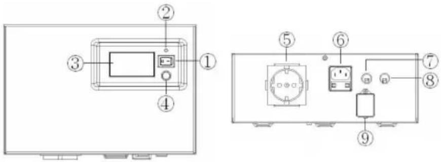
- Włącznik zasilania
natural_image
Line drawing of a rectangular electronic device with a central display and ventilation grille (no text or symbols)Conducted Emission: IEC/EN 62040-2...Category C2
Radiated Emission: IEC/EN 62040-2.....Category C2
Harmonic Current: IEC/EN61000-3-2
Voltage Fluctuations and Flicker: IEC/EN61000-3-3
EMS:
IEC/EN61000-4-2(ESD)
IEC/EN61000-4-3(RS)
IEC/EN61000-4-4(EFT)
IEC/EN61000-4-5(lightning surge)
IEC/EN61000-2-2 (Immunity to low frequency signals)
INSTALACE PŘÍSTROJE
VYBALENÍ
1. Hlavní vypínač
CyberPower Systems, Inc.
Website: www.cpsww.eu
Reliability. Quality. Value.
- SAFETY AND EMC INSTRUCTIONS
- DO NOT USE FOR MEDICAL OR LIFE SUPPORT EQUIPMENT!
- EMS:
- INSTALLING YOUR EPS
- UNPACKING
- AUTOMATIC VOLTAGE REGULATOR
- HARDWARE INSTALLATION GUIDE
- BASIC OPERATION
- DESCRIPTION
- Power Switch
- Power On Indicator
- Multifunction LCD Readout
- LCD Display Toggle / Selected Switch
- AC Outlet
- AC Inlet
- Input Fuse
- Black Battery Cable (Negative (-))
- Red Battery Cable (Positive (+))
- DC Fuse
- REPLACING THE BATTERY
- DEFINITIONS FOR ILLUMINATED LCD INDICATORS
- EPS STATUS INQUIRY AND FUNCTIONS SETUP
- GENERAL MODE
- SET-UP MODE
- FAULT WARNING DISPLAY AND ALARM
- CPS600E-DE Manual de utilizare
- INSTRUCTIUNI PRIVIND SIGURANȚAȘI COMPATIBILITATEA ELECTROMAGNETICĂ
- PREZENTARE
- Întrerupător
- AfiŞaj multifunctional LCD
- INSTALACJA EPS
- ROZPAKOWANIE
- OPIS
- INSTALACE PŘÍSTROJE
- VYBALENÍ
- Hlavní vypínač
Brand : CyberPower
Model : CPS600E-DE
Category : Charger