
VT-6054-4 - Fan V-TAC - Free user manual and instructions
Find the device manual for free VT-6054-4 V-TAC in PDF.


| Product Type | Decorative Ceiling Fan |
| Brand | V-TAC |
| Model | VT-6054-4 |
| Blade Span | 52 inches (132 cm) |
| Blade Material | MDF (Medium Density Fiberboard) |
| Number of Blades | 4 |
| Motor Size | 153 x 15 mm |
| Motor Weight | 2.3 kg |
| Speeds | 3 (Low, Medium, High) |
| Remote Control | Included with timer (1, 2, 4, 8 hours) |
| Light Kit | 2 x E27 sockets, max 40W each |
| Power Supply | 220-240V, 50Hz |
| Motor Power | 60W |
| Reversible Function | Yes (Summer/Winter mode) |
| Blade Angle | 13° |
| RPM | 220 ± 10 |
| Net Weight | 6.8 kg |
| Gross Weight | 7.6 kg |
| Warranty | 2 years (manufacturing defects) |
| Installation | Professional installation required; compatible with wooden and concrete ceilings |
| Cleaning | Disconnect power, use soft damp cloth; do not immerse in water |
| Safety Features | Minimum floor distance 2.3m; minimum outlet box capacity 45kg; all-pole disconnection switch required |
| Operating Environment | Indoor dry location only |
Frequently Asked Questions - VT-6054-4 V-TAC
User questions about VT-6054-4 V-TAC
0 question about this device. Answer the ones you know or ask your own.
Ask a new question about this device
Download the instructions for your Fan in PDF format for free! Find your manual VT-6054-4 - V-TAC and take your electronic device back in hand. On this page are published all the documents necessary for the use of your device. VT-6054-4 by V-TAC.
USER MANUAL VT-6054-4 V-TAC
- Make sure that the mains voltage matches the voltage stated on the rating label of the appliance.
- Check the power cord regularly for visible damage. If the cord is damaged, it must be replaced by the official Technical Support Service, in order to avoid any type of danger.
WARNING: Do not use the appliance if its cord, plug, or housing is damaged, nor after it malfunctions or has been dropped or damaged in any way.
- The appliance is not intended to be used by children under the age of 8. It can be used by children over the age of 8, as long as they are given continuous supervision.
- This appliance is not intended to be used by persons with reduced physical, sensory, or mental capabilities, or lack of experience or knowledge, unless they have been given supervision or instruction concerning the use of the appliance in a safe way by a person responsible for their safety, and understand the hazards involved.
- Supervise young children to make sure that they do not play with the appliance. Close supervision is necessary when the appliance is being used by or near children.
- Keep the appliance and its cord out of reach of children under the age of 8.
- Do not try to repair the appliance by yourself. Contact the official Technical Support Service for advice.
- Cleaning and maintenance must be carried out according to this instruction manual to make sure the appliance functions properly. Turn off and unplug the appliance before cleaning it.
• Make sure the fan is not placed near drapes, curtains, or any objects that may be drawn into the fan. -
The minimum distance between the fan blades and the floor must be 2.3 m. The minimum carrying capacity of the outlet box from which the fan is hung must be 45 kg.
-
Do not use the appliance in confined spaces with explosive or toxic vapours.
- This appliance can be used by children aged from 8 years and above and persons with reduced physical, sensory or mental capabilities or lack of experience and knowledge if they have been given supervision or instruction concerning use of the appliance in a safe way and understand the hazards involved. Children shall not play with the appliance. Cleaning and user maintenance shall not be made by children without supervision.
- Make sure you install all-poles disconnection switch with a minimum distance of 3 mm between poles in the supply wiring to the ceiling fan.
- Make sure the installation site will not allow the rotating fan blades to come into contact with any object and that there is a minimum distance of 150mm (6") from the blade tip to the wall or ceiling. Please note that the bigger this distance is, the more airflow the fan will produce.
- Switch off the power before connecting or repairing the fan.
- The electrical wiring must be in accordance with the local regulations.
- The fan must be properly grounded to avoid the risk of electric shocks. Never mount the fan in a moist or wet room. Be careful when working near the rotating blades.
- This appliance must be installed in accordance with the national electrical installation regulations.
- Ensure that the fan is switched off from the supply mains before removing the guard.
- If unusual oscillating movement is observed, immediately stop using the ceiling fan and contact the manufacturer, its service agent or suitably qualified persons.
- The replacement of parts of the safety suspension system device shall be performed by the manufacturer, its service agent or suitably qualified persons.
- The mounting of the suspension system shall be performed by the manufacturer, its service agent or suitably qualified person.
- In order to ensure your children's safety, please keep all packaging (plastic bags, boxes, polystyrene, etc.) away from their reach.
IMPORTANT: Shut off the main electric switch during installation or maintenance. It is recommended to switch off the plug of the automatic switch before the fan (Both mains and fan switch should be not powered).
- Do not use outdoors. The product must be installed in a dry place, where it is not exposed to water or moisture.
- Do not connect the fan motor to a dimmer switch. This could result in malfunction or motor damage.
- It is not recommended that ceiling fans and gas appliances operate in the same room at the same time.
- The fan must be completely turned off and stopped before reversing the fan direction. This will prevent the fan motor and controller from getting damaged.
- Do not insert any object into the fan blades during operation. This will damage the blades and upset the balance of the fan causing the unit to wobble.
- After the fan is completely installed make sure all base and fan blade fixings are secured and tightened to prevent any problems.
- Some of the connections may loosen due to the fan's natural movement. Check the support connections brackets and blade attachments twice a year to make sure they remain secured. If any are loose, tighten.
-
The use of electrical appliances requires notion of some basic rules, such as:
-
Do not touch the appliance with wet hands or feet
- Never expose the appliance to atmospheric conditions (rain, sun, etc.).
- Do not use the device next to potentially explosive or inflammable liquids or gases.
- This product is intended for household use ONLY & not for commercial or outdoor use.
- Keep batteries out of the reach of children and animals, they could cause damage if swallowed. If they were swallowed, contact your doctor immediately.
- If any visible signs of damage, holes or deterioration are observed, avoid direct contact between batteries and skin, eyes or mucous membranes. If batteries leak and get into contact with eyes, immediately wash them with abundant water. Contact your doctor immediately.
- Please make sure to turn off the power before starting the installation.
- Installation should only be done by a certified electrician.
This marking indicates that this product should not be disposed of with other household wastes.
Caution, risk of electric shock.
INTRODUCTION & WARRANTY
Thank you for selecting and buying V-TAC product. V-TAC will serve you the best. Please read these instructions carefully before starting the installation and keep this manual handy for future reference. If you have any another query, please contact our dealer or local vendor from whom you have purchased the product. They are trained and ready to serve you at the best. The warranty is valid for 2 years from the date of purchase. The warranty does not apply to damage caused by incorrect installation or abnormal wear and tear. The company gives no warranty against damage to any surface due to incorrect removal and installation of the product. The products are suitable for 10-12 Hours Daily operation. Usage of product for 24 Hours a day would void the warranty. This product is warranted for manufacturing defects only.
WEEE Number: 80133970
INSTRUCTION MANUAL
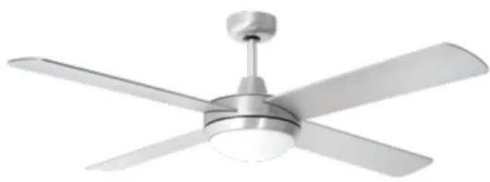
DECORATIVE CEILING FANS (VT-6054-4)
natural_image
Modern office ceiling fan with four blades and a central hub (no text or symbols visible)TECHNICAL DATA
1) 52" (132CM) Decorative ceiling fan
2) With forward and reverse function
3) 4 MDF blades
4) Powerful Motor: 153*15mm, 2.3kg
5) Revolutions per minute: 220±10 RPM
6) Blade angle 13°
7) 3 speeds and light remote control
8) 2XE27 light kit
9) Power:220V,50HZ,60W (power of the motor)
10) G.W.: 7.6KG / N.W.: 6.8KG
MULTI-LANGUAGE MANUAL QR CODE

Please scan the QR code to access the manual in multiple languages.
PARTS AND COMPONENTS
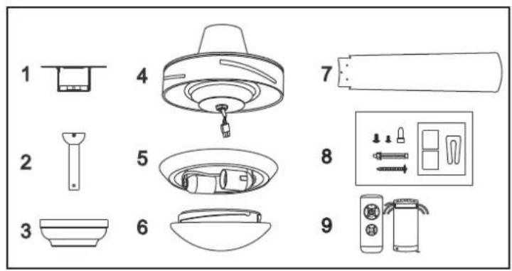
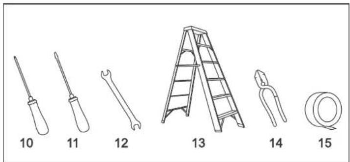
Tools and material required (not included)
- Mounting bracket
- Down rod and hanging ball
- Canopy
- Fan motor housing
- Light
- Glass shade
- Blades
- Screw kit, mounting bracket hardware (wire, nuts, rubber washers) and attachment hardware
- Remote control
- Screwdriver
- Flat-blade screwdriver
- Adjustable pliers or wrench
- Step ladder
- Wire cutter
- Electrical tape
1. BEFORE USE
Unpack your ceiling fan carefully then remove all parts and components and lay on a cloth or soft surface to avoid damage. Do not lay the motor housing on its side, the housing may get damaged. Before commencing installation, check that all parts are included.
2. PRODUCT ASSEMBLY
WARNING: All electrical tasks should only be undertaken after disconnection of electricity by removing fuses or turning off the circuit breaker to avoid risk of electric shocks.
ASSEMBLY STEPS:
2.1. INSTALLATION OF THE MOUNTING BRACKET
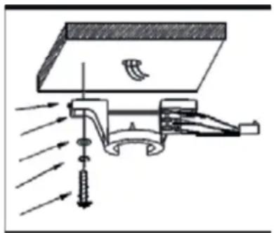
The hanger bracket must be screwed on to a firm flat surface. The structure to which it is installed must be able to withstand ten times the static weight of the fan. In case of installing the ceiling fan to a wooden joist, 2 self-tapping screws provided should be enough to support the ceiling fan. The washers provided must be placed in the following Order:
screw head > round washer > spring washer > mounting bracket > ceiling.
Screw the mounting bracket to the ceiling and make sure all connections are secure to prevent the fan from falling. Loosen the two canopy screws from the mounting bracket.
NOTE: Self-tapping screws are only suitable for wooden ceilings. In case of installing the ceiling fan to concrete ceilings or joists, use a drill for making the holes and stoppers or expansion screws (not included).
natural_image
Diagram of a mechanical device with arrows indicating flow or force direction (no text or symbols)2.2. INSTALLATION OF THE DOWN ROD AND HANGER BALL
natural_image
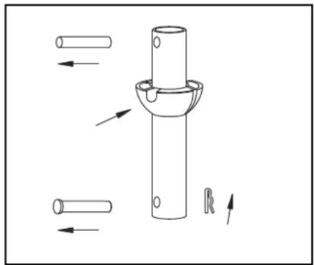
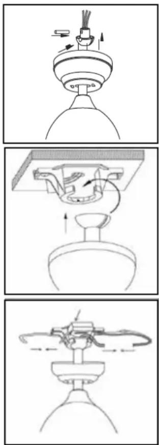
Technical line drawing of a mechanical component with arrows indicating assembly or movement (no text or symbols)- Unscrew the screw on the down rod's hanger ball, then loosen the hanger ball. Remove the stop pin from inside the down rod and remove the hanger ball from the rod.
- Remove the clevis pin and hairpin clip from the down rod. If you prefer using the longer down rod, install the hanger ball on it and make sure to move the earth wire from one to the other. Pass the electrical supply leads from the top of the motor all the way through the down rod until they come out the other end.
natural_image
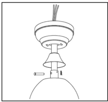
Line drawing of a ceiling-mounted air conditioner unit with cooling tower and base (no text or symbols)- Insert the down rod into the motor housing's hole and turn it in order to align the holes on both sides with the holes on the down rod.
- Pass the clevis pin through the holes so that it passes through the down rod too, be careful not to damage any of the wires. Pass the hairpin clip through the clevis pin so that it is securely fixed.
- Tighten all the screws set up to the moment. This will ensure minimum rod and fan tumbling.
- If screws are not properly tightened, the motor might oscillate. This could be dangerous.
- Once the above steps are all finished, install the hanger ball onto the down rod, insert the stop pin in the down rod and lift up the hanger ball. Then, tighten all the screws firmly so that all the elements are completely and securely fixed.
2.3. HANGING THE FAN TO THE MOUNTING BRACKET AND ATTACHING THE BLADES
- Lift the fan up to the mounting bracket, insert the hanger ball in the mounting bracket through the opening and carefully let it rest.
- Rotate the ball and make sure that the tab located in the mounting bracket is aligned with the hanging ball's slot.
- When aligned, the fan will automatically sit on its correct position. This will prevent rotation of the rod and fan when the unit is operating.
2.4. REMOTE CONTROL AND WIRING INSTRUCTION
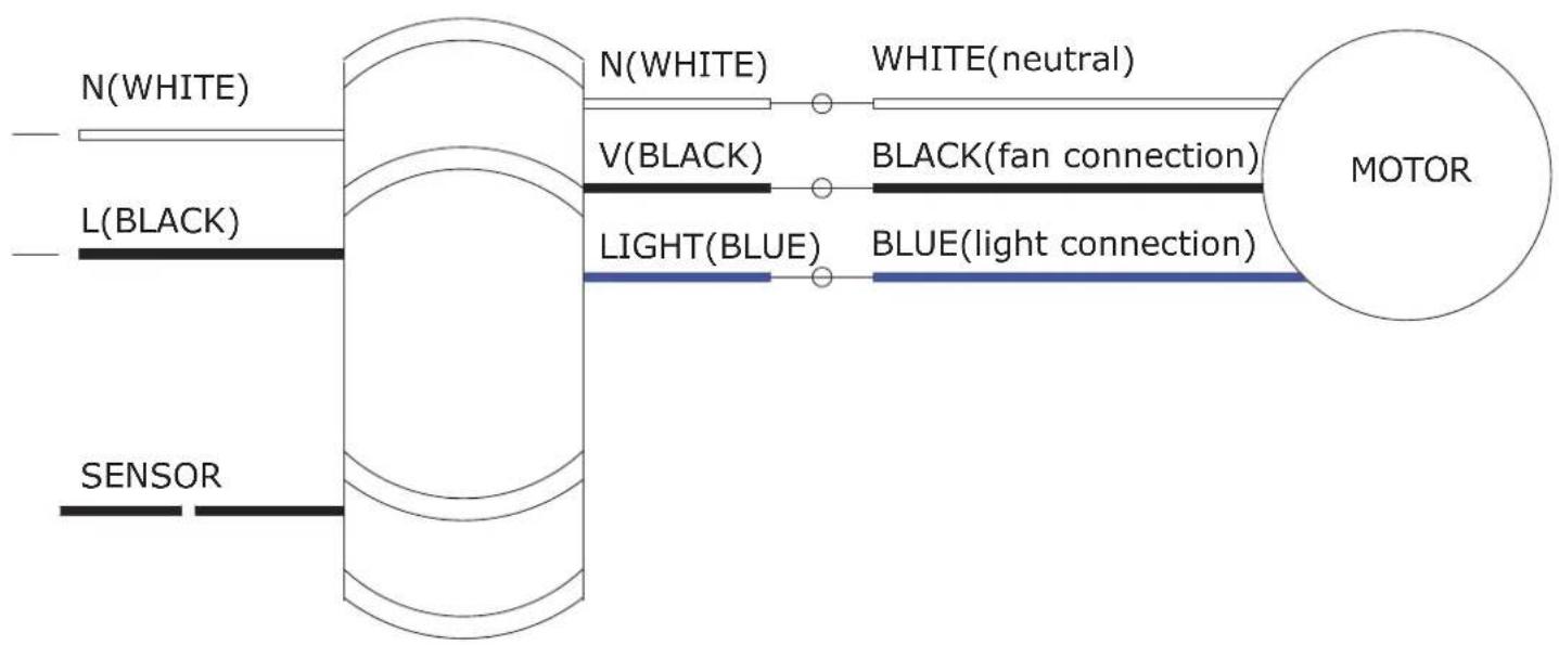
- Place the receiver through the hanging bracket and connect the wires following the colour codes.
- Connect the push connectors from the fan to the remote control as stated below:
WIRING DIAGRAM
flowchart
graph LR
    A["SENSOR"] --> B["L(BLACK)"]
    B --> C["N(WHITE)"]
    C --> D["V(BLACK)"]
    D --> E["LIGHT(BLUE)"]
    E --> F["BLUE(light connection)"]
    F --> G["MOTOR"]
    style A fill:#f9f,stroke:#333
    style G fill:#ccf,stroke:#333
    note1["N(WHITE)"]
    note2["V(BLACK)"]
    note3["LIGHT(BLUE)"]
    note4["WHITE(neutral)"]
    note5["BLACK(fan connection)"]
    note6["BLUE(light connection)"]
natural_image
Line drawing of a four-blade ceiling fan with airflow indicators (no text or symbols)2.5. BLADE ASSEMBLY
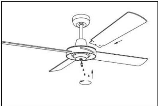
Insert the blades through the motor housing's side slots and align them with the 3 holes.
Secure the blades with 3 blade screws and ensure that the 3 blade screws are tightened properly. Do not over tighten the screws as this can damage the blades. Repeat this process for all blades.
NOTE: if installing more than 1 fan, be careful not to mix blades & screws as each model is designed with specific materials & parts.
natural_image
Diagram of a five-blade HVAC fan with internal components and airflow arrows (no text or labels)2.6. INSTALLING THE LED LIGHT AND GLASS SHADE
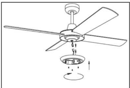
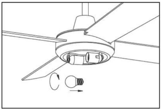
Connect the LED light's wires to the fan motor's wires. Align the lamp holder's screw holes with those on the motor and attach both parts by means of the screws provided.
natural_image
Technical line drawing of a ceiling fan with blades and internal components, showing directional arrows (no text or symbols)Insert-2-E27 Max.40W light bulb mounted on lamps.
natural_image
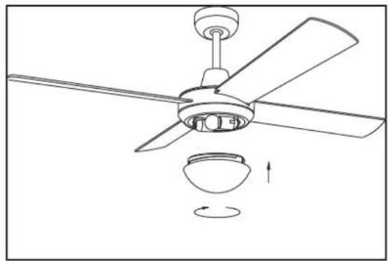
Line drawing of a four-blade ceiling fan with a bowl underneath and an arrow indicating rotation (no text or symbols)Carefully install the glass shade into the main body and turn it clockwise to lock it.
WARNING: Do not over tighten when installing the glass shade.
3. OPERATION
The direction switch on the fan body controls air flow:
- Winter function: press the switch UP for the blades to move warm air near the ceiling around.
- Summer function: press the switch DOWN for blades to create breeze and improve air circulation.
WARNING: Before using the direction switch, turn the fan off and make sure the fan has stopped rotating in order to prevent possible injuries and motor damage. Change direction by pushing the switch up or down when the fan is off.
REMOTE CONTROL
Use the remote control to turn the fan on and off and to change speed.
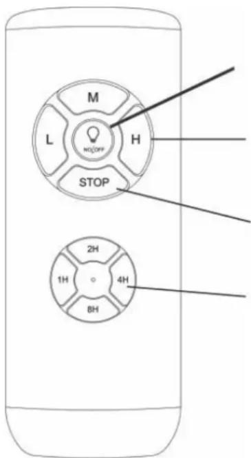
LIGHT ON/OFF
Fan Speed
H - Highest speed
M - Medium speed
L - Lowest speed
FAN STOP
Timer
1H-Fan auto turn off after 1 hour
2H-Fan auto turn off after 2 hours
4H-Fan auto turn off after 4 hours
8H-Fan auto turn off after 8 hours
REPLACING BATTERIES
- To replace the remote control batteries, press the battery cover and slide it towards the arrow direction.
- This remote control requires 1 x A23 12V battery.
- Reassemble the battery compartment cover.
WARNING:
- Always ensure the battery compartment cover is closed properly.
- Never leave the remote control directly exposed to sun light.
- Do not try recharging the discharged batteries by heating them or with a battery charger.
Rechargeable batteries are always specified as so. - Do not throw batteries into the fire, it could cause explosion.
4. CLEANING AND MAINTENANCE
- Always disconnect the fan from the power supply and allow it to stop before cleaning it.
- Clean the outside surface with a soft damp cloth.
WARNING:
- Make sure the power is turned off at the main fuse or circuit panel before you attempt any repairs.
- Do not immerse then fan in water.
- Never use scouring pads, abrasive or chemical cleaners.
- Clean your fan periodically. Use only a cloth or brush. Metal finishes are finished with a lacquer to prevent tarnishing.
- Do not allow the product's inside parts to get wet (especially the circuit plate), this could be very dangerous and damage the fan.
- While the product is not in use, make sure it is unplugged from the power supply. To store it, place it in its original box and save it in a fresh and dry place until it is used again.
- In case of fault or doubt, do not try to repair the fan by yourself to avoid risk of fire or electric shock.
5. TROUBLESHOOTING THE FAN DOES NOT START UP
- Check all the fuses or circuit breakers.
- Turn off the electrical power and check all wire connections.
THE FAN EMITS NOISES
- Always allow a few days "break in" time for any new fan at medium or high speed. Try to diagnose the exact location of the noise by listening carefully from several sides (blades, motor, light kit, etc.) The fan noise can come from a light kit.
- Make sure all screws in the fan assembly and light kit are tight and properly threaded. If not, then turn off the power and tighten the screws. Tighten these screws at least once a year because they may loosen slowly over time and cause a clicking noise.
- Make sure the light kit is securely fastened to the fan, and all glass screws are finger tightened only. Do not tighten with pliers or a screw driver.
- Make sure the mounting bracket is installed snugly to the junction box.
- Make sure wire nuts in the switch housing or the canopy are not rattling against each other or against the housing's wall. Wrap with electrical tape if necessary.
- Make sure the canopy is not touching the ceiling.
- Assure that the screws fastening the blade holders to the motor are tight and the lock washers provided for that purpose have been used.
THE FAN DOES NOT PRODUCE MUCH AIR
-
The fan may be running in reverse, so air is directed upward.
-
The room may contain items that obstruct the airflow.
- The fan may be too small for the size of the room.
FAN WOBBLING
NOTE: A small amount of wobble is considered acceptable and should not be considered a defect.
- Make sure the mounting bracket is fixed tightly to the ceiling with no movement at all. Tighten screws if necessary.
- Make sure all screws holding the blades to the blade support and blade support to motor are tight. Make sure the light kit and the glass screws are tight.
In case of any query/issue with the product, please reach out to us at: support@v-tac.eu For More products range, inquiry please contact our distributor or nearest dealers. V-TAC EUROPE LTD. Bulgaria, Plovdiv 4000, bul.L.Karavelow 9B
- INTRODUCTION & WARRANTY
- TECHNICAL DATA
- MULTI-LANGUAGE MANUAL QR CODE
- PARTS AND COMPONENTS
- BEFORE USE
- PRODUCT ASSEMBLY
- ASSEMBLY STEPS:
- INSTALLATION OF THE MOUNTING BRACKET
- screw head > round washer > spring washer > mounting bracket > ceiling.
- INSTALLATION OF THE DOWN ROD AND HANGER BALL
- HANGING THE FAN TO THE MOUNTING BRACKET AND ATTACHING THE BLADES
- REMOTE CONTROL AND WIRING INSTRUCTION
- BLADE ASSEMBLY
- INSTALLING THE LED LIGHT AND GLASS SHADE
- OPERATION
- REMOTE CONTROL
- LIGHT ON/OFF
- Fan Speed
- FAN STOP
- Timer
- REPLACING BATTERIES
- WARNING:
- CLEANING AND MAINTENANCE
- TROUBLESHOOTING THE FAN DOES NOT START UP
- THE FAN EMITS NOISES
- THE FAN DOES NOT PRODUCE MUCH AIR
- FAN WOBBLING
Brand : V-TAC
Model : VT-6054-4
Category : Fan