OHTC100H - Heating Otsein-Hoover - Free user manual and instructions
Find the device manual for free OHTC100H Otsein-Hoover in PDF.


| Product Type | Electric Storage Water Heater |
| Brand | Otsein-Hoover |
| Model | OHTC100H |
| Volume | 100 L |
| Dimensions (A x B x C x D) | 970 x 450 x 450 x 447 mm |
| Rated Power | 2000 W |
| Rated Voltage | 220-240 V AC |
| Rated Pressure | 0.5 MPa (max), 0.1 MPa (min) |
| Maximum Water Temperature | 75 °C |
| Protection Class | I |
| Waterproof Grade | IPX4 |
| Temperature Control | Adjustable thermostat knob with indicators (Power, Heating) |
| Pressure Relief Valve | Included, must be installed at cold water inlet |
| Safety Features | Thermal cut-out, manual reset button, earthing required |
| Anode Rod | Magnesium anode, replaceable |
| Installation | Wall-mounted, requires solid wall or reinforcement |
| Connection Size | G1/2" for water pipes |
| Energy Efficiency Class | C (water heating energy efficiency 36%) |
| Annual Electricity Consumption | 1423 kWh |
| Mixed Water at 40 °C (V40) | 111 L |
| Maintenance | Drain water if not used in freezing conditions; clean tank and replace anode periodically |
Frequently Asked Questions - OHTC100H Otsein-Hoover
User questions about OHTC100H Otsein-Hoover
0 question about this device. Answer the ones you know or ask your own.
Ask a new question about this device
Download the instructions for your Heating in PDF format for free! Find your manual OHTC100H - Otsein-Hoover and take your electronic device back in hand. On this page are published all the documents necessary for the use of your device. OHTC100H by Otsein-Hoover.
USER MANUAL OHTC100H Otsein-Hoover
natural_image
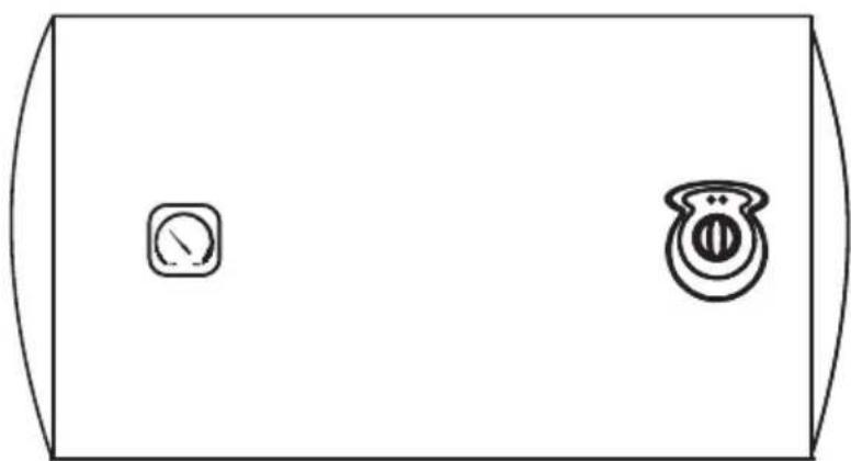
Simple line drawing of a rectangular container with two circular symbols on the sides (no text or labels)The diagram above is just for reference. Please take the appearance of the actual product as the standard.
General Remark
- The installation and maintenance has to be carried out by qualified professionals or authorized technicians.
- The manufacturer shall not be held responsible for any damage or malfunction caused by wrong installation or failing to comply with following instructions included in this pamphlet.
- For more detailed installation and maintenance guidelines, please refer to below chapters.
TABLE OF CONTENTS
TITLE PAGE
1.CAUTIONS....(2)
2.PRODUCT INTRODUCTION ....(3)
3. UNIT INSTALLATION ....(5)
4.METHODS OF USING....(6)
5.MAINTENANCE ......(7)
6.TROUBLESHOOTING....(8)
7.PRODUCE INFORMATION WITH EU REGULATION .....(9)
8.DESCRIPTION TO ANNEX I....(11)
1. CAUTIONS
Before installing this water heater, check and confirm that the earthing on the supply socket is reliably grounded. Otherwise, the electrical water heater can not be installed and used. Do not use extension boards. Incorrect installation and use of this electrical water heater may result in serious injuries and loss of property.
Special Cautions
- The supply socket must be earthed reliably. The rated current of the socket shall not be lower than 16A. The socket and plug shall be kept dry to prevent electrical leakage.
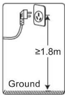
- The installation height of the supply socket shall not be lower than 1.8m.
- The wall in which the electrical water heater is installed shall be able to bear the load more than two times of the heater filled fully with water without distortion and cracks. Otherwise, other strengthening measures shall be adopted.
- The pressure relief valve attached with the heater must be installed at the cold water inlet of this heater(see Fig.1), and make sure it is not exposed in the foggy. The water may be outflowed from pressure relief valve, so the outflow pipe must open wide in the air; The pressure relief valve need to be checked and cleaned regularly, so as to make sure it will not be blocked.
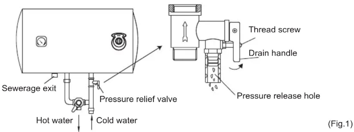
- When using the heater for the first time(or the first use after maintenance), the heater can not be switched on until it has been filled fully with water. When filling the water, at least one of the outlet valves at the outlet of the heater must be opened to exhaust the air. This valve can be closed after the heater has been filled fully with water.
- The water heater is not intended for use by persons(including children)with reduced physical, sensory or mental capabilities, or lack of experience and knowledge, unless they have been given supervision or instructions concerning use of the appliance by a person responsible for their safety. Children should be supervised to ensure that they do not play with the heater.
- During heating, there may be drops of water dripping from the pressure release hole of the pressure relief valve. This is a normal phenomenon. If there is a large amount of water leak, please contact customer care center for repair. This pressure release hole shall, under no circumstances, be blocked; otherwise, the heater may be damaged, even resulting in accidents.
- The drainage pipe connected to the pressure release hole must be kept sloping downwards.
- Since the water temperature inside the heater can reach up to 75°C, the hot water must not be exposed to human bodies when it is initially used. Adjust the water temperature to a suitable temperature to avoid scalding.
-
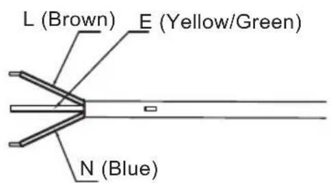
If the flexible power supply cord is damaged, the special supply cord provided by the manufacturer must be selected, and replaced by the professional maintenance personnel.
-
If any parts and components of this electrical water heater are damaged please contact customer care center for repair.
- This appliance is not intended for use by persons (including children) with reduced physical, sensory or mental capabilities, or lack of experience and knowledge, unless they have been given supervision or instruction concerning use of the appliance by a person responsible for their safety.
- Children should be supervised to ensure that they do not play with the appliance.
- The maximum inlet water pressure is 0.5MPa; the minimum inlet water pressure is 0.1MPa, if this is necessary for the correct operation of the appliance.
- The water may drip from the discharge pipe of the pressure-relief device and that this pipe must be left open to the atmosphere; The pressure-relief device is to be operated regularly to remove lime deposits and to verify that it is not blocked;
- In order to drain away the water inside the inner container, it can be drained away from the pressure release valve. Twist the thread screw of the pressure release valve off, and lift the drain handle upwards.(See Fig.1) A discharge pipe connected to the pressure-relief device is to be installed in a continuously downward direction and in a frost-free environment.
2. PRODUCT INTRODUCTION
2.1 Technical Performance Parameters
| Model | Volume (L) | Rated Power (W) | Rated Voltage (ACV) | Rated Pressure (MPa) | Max Of Water Temperature (°C) | Protection Class | Waterproof Grade |
| I | IPX4750.75220-24 | ||||||
| I | IPX4750.75220-24 |
2.2 Brief introduction of product structure
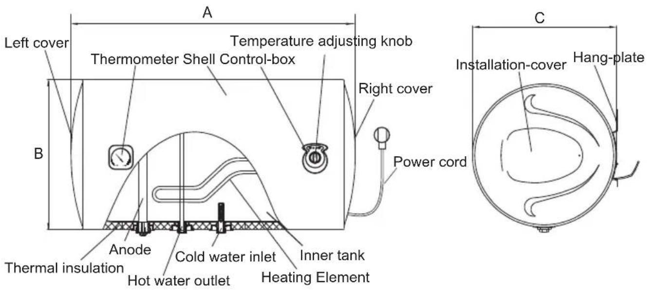
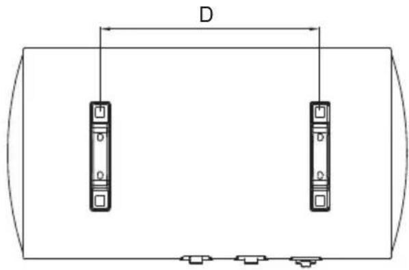
| OHTC80H | OHTC100H | |
| A | 815 | 970 |
| B | 450 | 450 |
| C | 450 | 450 |
| D | 297 | 447 |
(Note: All dimensions are in mm)
2.3 Internal Wire Diagram
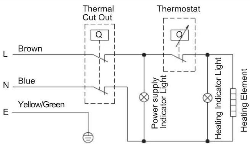
flowchart
graph TD
    A["Thermal Cut Out"] --> B["Q"]
    C["Thermostat"] --> D["Q"]
    E["Power supply Indicator Light"] --> F["Light"]
    G["Heating Indicator Light"] --> H["Light"]
    I["Yellow/Green"] --> J["Light"]
    K["L Brown"] --> L["Blue"]
    M["N"] --> N["Blue"]
    O["E"] --> P["Yellow/Green"]
WIRING DIAGRAM
3. UNIT INSTALLATION
3.1 Installation Instruction
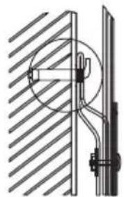
① This electrical water heater shall be installed on a solid wall. If the strength of the wall cannot bear the load equal to two times of the total weight of the heater filled fully with water, it is then necessary to install a special support.
Incase of hollow bricks wall, ensure to fill it with cement concrete completely.
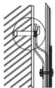
② After selecting a proper location, determine the positions of the two install holes used for expansion bolts with hook (determined according to the specification of the product you select). Make two holes in the wall with the corresponding depth by using a chopping bit with the size matching the expansion bolts attached with the machine, insert the screws, make the hook upwards, tighten the nuts to fix firmly, and then hang the electric water heater on it (see Fig.2).
natural_image
Technical diagram of a mechanical assembly with hatched background and internal circular component (no text or symbols)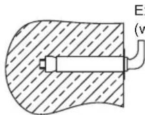
Expansion bolt (with hook)
(Fig.2)
③ Install the supply socket in the wall. The requirements for the socket are as follows:250V/10A, single phase, three electrodes. It is recommended to placed the socket on the right above the heater. The height of the socket to the ground shall not be less than 1.8m (see Fig.3). If there is fault on power cable, it should be replaced by the manufacturers, agencies or qualified person who is able to do this so as to ensure the safety.
(Fig.3)
④ If the bathroom is too small, the heater can be installed at another place without sun-scorched and rain-drenched. However, in order to reduce the pipeline heat losses, the installation position of the heater shall be closed to the location shall be as near as possible to the heater.
3.2 Pipelines Connection
① The dimension of each pipe part is G1/2"; The massive pressure of inlet should use Pa as the unit; The minimum pressure of inlet should use Pa as the unit.
② Connection of pressure relief valve with the heater on the inlet of the water heater.
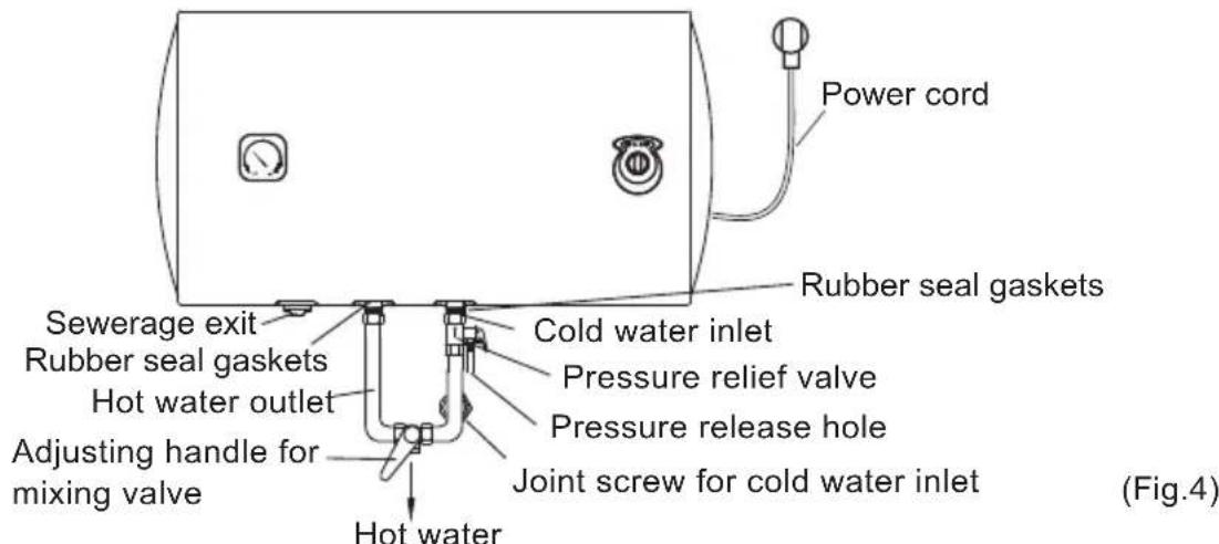
③ In order to avoid leakage when connecting the pipelines, the rubber seal gaskets provided with the heater must be added at the end of the threads to ensure leak proof joints (see Fig.4).
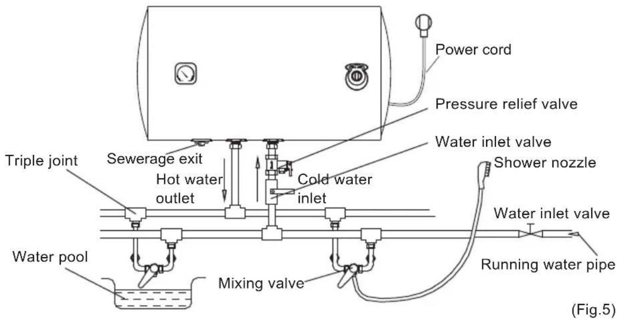
④ If the users want to realize a multi-way supply system, refer to the method shown in fig.5 for connection of the pipelines.

NOTE
Please be sure to use the accessories provided by our company to install this electric water heater. This electric water heater can not be hung on the support until it has been confirmed to be firm and reliable. Otherwise, the electric water heater may drop off from the wall, resulting in damage of the heater, even serious accidents of injury. When determining the locations of the bolt holes, it shall be ensured that there is a clearance not less than 0.2m on the right side of the electric heater, to convenient the maintenance of the heater, if necessary.
4. METHODS OF USING
- First, open any one of the outlet valves at the outlet of the water heater, then, open the inlet valve. The water heater gets filled with water. When water flows out of the outlet pipe it implies that the heater has been filled fully with water, and the outlet valve can be closed.
During normal operation, the inlet valve shall be always kept open.
- If the “Power” indicator lights up, the thermostat will automatically control the temperature. When the water temperature inside the heater has reached the set temperature, it will switch off automatically, when the water temperature falls below the set point the heater will be turned on automatically to restore the heating.
4.1 Operating Of The Unit
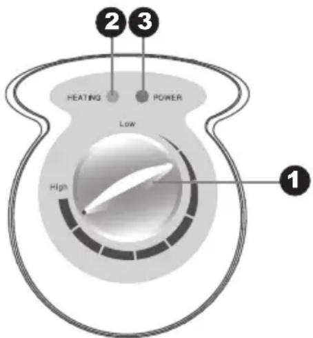
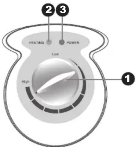
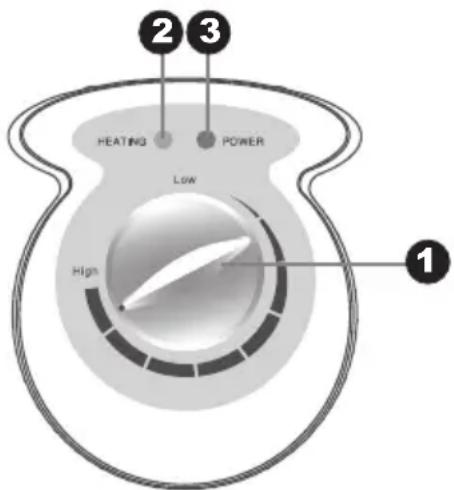
① "Thermostat" knob, rotate the thermostat knob to set the temperature. Maximum set temperature is 75 °C. Then the heating indicator light on.
② "Power" indicator light, plug in the power, the power indicator light will light ON reservation.
③ “Heating indicator” light, when the water is heated to the set temperature. The indicator light is off, the water heater will be in a state of insulation.
5. MAINTENANCE

WARNING
Do cut off power supply before maintenance, to avoid danger like electric shock.
- Check the power plug and outlet as often as possible. Secure electrical contact and also proper grounding must be provided. The plug and outlet must not heat excessively.
- If the heater is not used for a long time, especially in regions with low air temperature(below 0°C), it is necessary to drain water from the heater to prevent damage of the water heater, due to water freezing in the internal tank.(Refer Cautions in this manual for the method to drain away the water from the inner container).
- To ensure long reliable water heater operation, it is recommended to regularly clean the internal tank and remove deposits on the electric heating element of the water heater, as well as check condition (fully decomposed or not) of the magnesium anode and, if necessary, replace it with a new one in case of full decomposition. Tank cleaning frequency depends on hardness of water located in this territory. Cleaning must be performed by special maintenance services. You can ask the seller for address of the nearest service center.
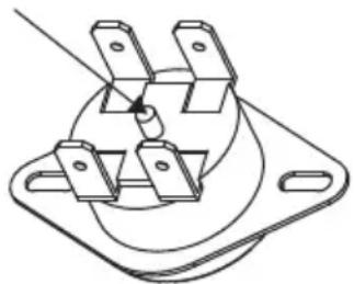
- The water heater is equipped with a thermal switch, which cuts off power supply of the heating element upon water overheating or its absence in the water heater. If the water heater is connected to the mains, but water is not heated and the indicator doesn't light up, then the thermal switch was switched off or not switched on. To reset the water heater to the operating condition, it is necessary to:
- De-energize the water heater, remove the plate of the side/lower cover.
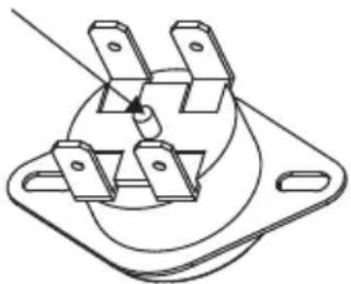
- Press the button, located at the center of the thermal switch, see Fig.7;
- If the button is not pressed and there is no clicking, then you should wait until the thermal switch cools down to the initial temperature.
Manual reset button
natural_image
Technical line drawing of a three-pin electrical socket with mounting flanges (no text or symbols)(Fig.7)

WARNING
Non-professionals are not allowed to disassemble the thermal switch to reset. Please contact professionals to maintain. Otherwise our company will not take responsibility if any quality accident happens because of this.
6. TROUBLESHOOTING
| Failures Reasons Treatment | ||
| The heating indicator light is off. | Failures of the temperature controller. | Contact with the professional personnel for repair. |
| No water coming out of the hot water outlet. | 1. The running water supply is cut off.2. The hydraulic pressure is too low.3. The inlet valve of running water is not open. | 1. Wait for restoration of running water supply.2. Use the heater again when the hydraulic pressure is increased.3. Open the inlet valve of running water. |
| The water temperature is too high. | Failures of the temperature control system. | Contact with the professional personnel for repair. |
| Water leak. | Seal problem of the joint of each pipe. | Seal up the joints. |

NOTE
Parts illustrated in this use and care manual are indicative only, parts provided with the product may differ with illustrations. This product is intended for household use only. Specifications are subject to change without notice.
7. PRODUCE INFORMATION WITH EU REGULATION
The electrical storage water heater OHTC80H of the company Candy Hoover Group srl was tested with a declared load profile of the sizeM"
The product fulfills and corresponds to the requirements of the commission regulation standards (No 814/2013) for electrical storage water heater and achieved a water heating energy efficiency of
$$ \eta_ {\mathrm{wh}} = 36 \% $$
that correspond to the water heating efficiency class
In accordance with Annex II Energy Efficiency Classestiale 1 of the commission regulation (No 812/2013)
The evaluation of the result of this report with respect of conformity with the related commissio regulation (No 812/2013 and 814/2019) is only a part of the conformity assessment to achieve the ErP-Label.
Electricity consumption, water heating energy efficiency _wh and mixed water at 40^ (V40)
| Description Parameter Value Unit | |||
| k-Value k | 0.23 | ||
| Smart control compliance smart | 0 | ||
| Smart control factor SCF | 0 | ||
| Conversion coefficient CC | 2.5 | ||
| Ambient correction term Q | cor | -0.459 | kWh |
| Referenct energy | Q_ref | 5.845 | kWh |
| Useful energy content Q | H2O | 5.938 | kWh |
| Correction ratio of reference and useful energy | ref Q_H2O | 0.984 | kWh |
| Daily electricity consumption (measured) | test_elec | 6.815 | kWh |
| Water temperature at the beginning of the 24h measurement cycle | T3 | 57.6 | °C |
| Water temperature at the end of the 24h measurement cycle | T5 | 58.3 | °C |
| Storage volume | M_act | 80.6 | kg |
| Storage volume | C_act | 80.6 | L |
| Daily electricity consumption (corrected) | elec | 6.644 | kWh |
| Water heating energy efficiency | η_wh | 36.2 | |
| Annual Electricity Consumption | AEC | 1419 | kWh |
| Water heating energy efficiency class | C | ||
| Water temperature without tapping | T_set | 58 | °C |
| Average water temperature of outlet warm water | θ_p' | 54.8 | °C |
| Average water temperature of inlet cold water | θ_c | 10.4 | °C |
| Normalised value of the average temperature | θ_p | 54.8 | °C |
| Volume that delivered water of at least 40°C | V_40exp | 57 | L |
| Calculated volume that delivered hot water of at least 40°C | V_40 | 85 | L |
The electrical storage water heater OHTC100H of the company Candy Hoover Group srl was tested with a declared load profile of the sizeM"
The product fulfills and corresponds to the requirements of the commission regulation standards (No 814/2013) for electrical storage water heater and achieved a water heating energy efficiency of
$$ \eta_ {\mathrm{wh}} = 36 \% $$
that correspond to the water heating efficiency class"
In accordance with Annex II Energy Efficiency Classestiale 1 of the commission regulation (No 812/2013)
The evaluation of the result of this report with respect of conformity with the related commission regulation (No 812/2013 and 814/2019) is only a part of the conformity assessment to achieve the ErP-Label.
Electricity consumption, water heating energy efficiency _wh and mixed water at 40^ (V40)
| Description Parameter Value Unit | |||
| k-Value k | 0.23 | ||
| Smart control compliance smart | 0 | ||
| Smart control factor SCF | 0 | ||
| Conversion coefficient CC | 2.5 | ||
| Ambient correction term Q | cor | -0.473 | kWh |
| Referenct energy | Q_ref | 5.845 | kWh |
| Useful energy content Q | H2O | 5.947 | kWh |
| Correction ratio of reference and useful energy | ref Q_H2O | 0.983 | kWh |
| Daily electricity consumption (measured) | te Q_elec | 6.772 | kWh |
| Water temperature at the beginning of the 24h measurement cycle | T3 | 58.1 | °C |
| Water temperature at the end of the 24h measurement cycle | T5 | 58 | °C |
| Storage volume | M_act | 100.9 | kg |
| Storage volume | C_act | 100.9 | L |
| Daily electricity consumption (corrected) | e_elec | 6.667 | kWh |
| Water heating energy efficiency | η_wh | 36.1 | |
| Annual Electricity Consumption | AEC | 1423 | kWh |
| Water heating energy efficiency class | C | ||
| Water temperature without tapping | T_set | 58 | °C |
| Average water temperature of outlet warm water | θ_p' | 56.2 | °C |
| Average water temperature of inlet cold water | θ_c | 10.3 | °C |
| Normalised value of the average temperature | θ_p | 56.2 | °C |
| Volume that delivered water of at least 40°C | V_40exp | 72 | L |
| Calculated volume that delivered hot water of at least 40°C | V_40 | 111 | L |
8. DESCRIPTION TO ANNEX I

DESCRIPTION TO ANNEX I
(1)supplier's name or trade mark
(2) supplier's model identifier
(3) the declared load profile, expressed by the appropriate letter and typical usage in accordance with Table 3 of Annex VII
(4) the water heating energy efficiency class of the model, determined in accordance with point 1 of Annex II
(5) the water heating energy efficiency in %, rounded to the nearest integer
(6) the annual electricity consumption in KWh in terms of final energy and/or the annual fuel consumption in GJ in terms of GCV, rounded to the nearest integer and calculated in accordance with point 4 of Annex VIII
(7) the thermostat temperature settings of the water heater, as placed on the market
(8) the daily electricity consumption Q elec in KWh, rounded to three decimal places
(9) the declared load profile, expressed by the appropriate letter in accordance with Table 1 of this Annex
(10) the mixed water at 40^ C V40 in litres, rounded to the nearest integer
(11) maximum temperature of the thermostat
(12) 'out of the box-mode' is the standard operating condition, setting or mode set by the manufacturer at factory level, to be active immediately after the appliance installation, suitable for normal use by the end-user according to the water tapping pattern for which the product has been designed and placed on the market
(13) the water heating energy efficiency in %, rounded to one decimal place
(14) All specific precautions for assembly, installation and maintenance are described in the operating and installation instructions. Read and follow the operating and installation instructions.
(15) All of the data that is included in the product information was determined by applying the specifications of the relevant European directives. Differences to product information listed elsewhere may result in different test conditions. Only the data that is contained in this product information is applicable and valid.
The product is subject to change without notice. Please keep this manual properly.
HOOVER
Otsein
MANUAL DE OPERACIÓN
TERMO ELÉCTRICO
Modelo: OHTC80H
OHTC100H
natural_image
Simple line drawing of a rectangular container with two circular symbols on the sides (no text or labels)natural_image
Technical diagram of a mechanical assembly with hatched background and internal circular component (no text or symbols)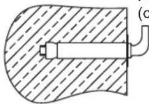
natural_image
Diagram of a mechanical component with hatched fill and labeled point (c), no readable text or symbols present.(Figura 3)
- If the “Power” indicator lights up, the thermostat will automatically control the temperature. When the water temperature inside the heater has reached the set temperature, it will switch off automatically, when the water temperature falls below the set point the heater will be turned on automatically to restore the heating.
4.1 Operating Of The Unit
① "Thermostat" knob, rotate the thermostat knob to set the temperature. Maximum set temperature is 75 °C. Then the heating indicator light on.
② “Power” indicator light, plug in the power, the power indicator light will light ON reservation.
③ “Heating indicator” light, when the water is heated to the set temperature. The indicator light is off, the water heater will be in a state of insulation.
5. MANTENIMIENTO

ADVERTENCIA
- The water heater is equipped with a thermal switch, which cuts off power supply of the heating element upon water overheating or its absence in the water heater. If the water heater is connected to the mains, but water is not heated and the indicator doesn't light up, then the thermal switch was switched off or not switched on. To reset the water heater to the operating condition, it is necessary to:
- De-energize the water heater, remove the plate of the side/lower cover.
- Press the button, located at the center of the thermal switch, see Fig.7;
- If the button is not pressed and there is no clicking, then you should wait until the thermal switch cools down to the initial temperature.
Manual reset button
natural_image
Technical line drawing of a three-pin electrical socket with mounting flanges (no text or symbols)(Fig.7)

WARNING
Non-professionals are not allowed to disassemble the thermal switch to reset. Please contact professionals to maintain. Otherwise our company will not take responsibility if any quality accident happens because of this.
6. RESOLUCION DE PROBLEMAS
natural_image
Simple line drawing of a rectangular container with two circular symbols on the sides (no text or labels)Observação Geral
natural_image
Pure diagram of two vertical connectors with a labeled dimension D, no text or symbols present| OHTC80H | OHTC100H | |
| A | 815 | 970 |
| B | 450 | 450 |
| C | 450 | 450 |
| D | 297 | 447 |
② After selecting a proper location, determine the positions of the two install holes used for expansion bolts with hook (determined according to the specification of the product you select). Make two holes in the wall with the corresponding depth by using a chopping bit with the size matching the expansion bolts attached with the machine, insert the screws, make the hook upwards, tighten the nuts to fix firmly, and then hang the electric water heater on it (see Fig.2).
natural_image
Technical diagram of a mechanical assembly with hatched background and circular component (no text or symbols)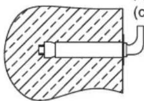
natural_image
Diagram of a mechanical component with hatched fill and labeled point (c), no readable text or symbols present.(Fig.3)
- If the “Power” indicator lights up, the thermostat will automatically control the temperature. When the water temperature inside the heater has reached the set temperature, it will switch off automatically, when the water temperature falls below the set point the heater will be turned on automatically to restore the heating.
4.1 Operating Of The Unit
① "Thermostat" knob, rotate the thermostat knob to set the temperature. Maximum set temperature is 75 °C. Then the heating indicator light on.
② “Power” indicator light, plug in the power, the power indicator light will light ON reservation.
③ “Heating indicator” light, when the water is heated to the set temperature. The indicator light is off, the water heater will be in a state of insulation.
5. MANUTENÇÃO

ALERTA
natural_image
Pure technical line drawing of a mechanical component with mounting flanges and a central pin (no text or symbols)(Fig.9)

ALERTA
- General Remark
- TABLE OF CONTENTS
- TITLE PAGE
- CAUTIONS
- Special Cautions
- PRODUCT INTRODUCTION
- Technical Performance Parameters
- Brief introduction of product structure
- Internal Wire Diagram
- UNIT INSTALLATION
- Installation Instruction
- Pipelines Connection
- NOTE
- METHODS OF USING
- Operating Of The Unit
- MAINTENANCE
- WARNING
- TROUBLESHOOTING
- PRODUCE INFORMATION WITH EU REGULATION
- DESCRIPTION TO ANNEX I
- DESCRIPTION TO ANNEX I
- HOOVER
- Otsein
- MANUAL DE OPERACIÓN
- TERMO ELÉCTRICO
- MANTENIMIENTO
- ADVERTENCIA
- RESOLUCION DE PROBLEMAS
- Observação Geral
- MANUTENÇÃO
- ALERTA
Brand : Otsein-Hoover
Model : OHTC100H
Category : Heating