
HMW-LGW-O-DR-GS-EU - Home Automation Homematic IP - Free user manual and instructions
Find the device manual for free HMW-LGW-O-DR-GS-EU Homematic IP in PDF.


| Product Type | RS485 LAN Gateway for Homematic Wired System |
| Model | HMW-LGW-O-DR-GS-EU |
| Brand | Homematic IP |
| Power Supply | 24 VDC / SELV |
| Max. Power Consumption | 100 mA (max.) |
| Standby Power Consumption | 0.75 W |
| Degree of Protection | IP20 |
| Ambient Temperature Range | 0 - 35 °C |
| Housing Dimensions (W x H x D) | 35 x 87 x 64 mm (2 units width DIN rail) |
| Weight | 76 g |
| Network Interface | Ethernet 10/100Base-T |
| Communication Protocol | RS485 Bus (Homematic Wired) |
| Protection Class | III |
| Mounting Type | DIN rail (EN50022) in distribution board |
| Bus Terminator Required | Yes |
| Max. Bus Cable Length | 50 m |
| Max. Devices per Bus Segment | 127 |
| Supply Voltage Cable Cross Section | Rigid: 0.14 - 2.5 mm²; Flexible with ferrule: 0.14 - 1.5 mm² |
| Ethernet Cable Requirement | CAT5 FTP or better |
| Indoor Use Only | Yes |
| Key Features | Enables LAN communication between Homematic Wired devices and CCU2; DIN rail installation; reset button; power/status LED |
| Included Accessories | Ethernet cable, installation and operating manual |
| Disposal | Do not dispose with household waste; take to WEEE collection point |
| Maintenance | No user maintenance required; repairs only by trained professionals |
| Certification | CE mark |
Frequently Asked Questions - HMW-LGW-O-DR-GS-EU Homematic IP
User questions about HMW-LGW-O-DR-GS-EU Homematic IP
0 question about this device. Answer the ones you know or ask your own.
Ask a new question about this device
Download the instructions for your Home Automation in PDF format for free! Find your manual HMW-LGW-O-DR-GS-EU - Homematic IP and take your electronic device back in hand. On this page are published all the documents necessary for the use of your device. HMW-LGW-O-DR-GS-EU by Homematic IP.
USER MANUAL HMW-LGW-O-DR-GS-EU Homematic IP
Installation and operating manual (p. 30)
RS485 LAN Gateway, Hutschienenmontage
RS485 LAN Gateway, for mounting on DIN rails
HMW-LGW-O-DR-GS-EU
Printed in Hong Kong.
Documentation © 2013 eQ-3 AG, Germany
All rights reserved. This manual may not be reproduced in any format, either in whole or in part, nor may it be duplicated or edited by electronic, mechanical or chemical means, without the written consent of the publisher.
Typographical and printing errors cannot be excluded. However, the information contained in this manual is reviewed on a regular basis and any necessary corrections will be implemented in the next edition. We accept no liability for technical or typographical errors or the consequences thereof.
All trademarks and industrial property rights are acknowledged.
Printed in Hong Kong. Translation of original manual. Changes may be made without prior notice as a result of technical advances.
103850
Version 1.5
Table of contents
1 Information about this manual ..... 32
2 Hazard information....32
3 Function 34
4 General system information about Homematic 37
5 General information about the bus system ... 38
5.1 General information on the installation.....38
5.2 Topology of the bus system ..... 38
6 Installation 39
6.1 Installation instructions for remote components 45
6.2 Example connection with one sub-distribution board 47
6.3 Example connection with more than one sub-distribution board.....48
6.4 Connection and installation example ..... 49
7 Integration into network (LAN) ..... 50
8 Restoring the factory settings....51
9 Disassembly....53
10 Maintenance and cleaning....53
11 Scope of supply 54
12 Technical data 54
1 Information about this manual
Read this manual carefully before beginning operation with your Homematic components. Keep the manual handy for later consultation! If you hand over the device to other persons for use, please hand over the operating manual as well.
Symbols used:

Attention! This indicates a hazard.

Note. This section contains important additional information.
2 Hazard information

The device described is part of a building installation. When planning and setting up electrical systems, the pertinent standards and regulations of the respective country of installation are to be observed.

Work on and in low-voltage installations is only permitted by qualified electricians (in accordance with VDE 0100). Applicable accident
prevention regulations must be complied with whilst such work is being carried out. Disconnect the power to devices before working on them to prevent electrocution (switch circuit breaker).

Ignoring installation instructions can cause fires or other hazards (see sec. 6).

The device may only be operated indoors and must be protected from the effects of damp and dust, as well as solar or heat radiation.

Using the device for any purpose other than that described in this operating manual does not fall within the scope of intended use and shall invalidate any warranty or liability.

Do not open the device: it does not contain any components that need to be serviced by the user. There is a risk of electrical shock by opening the device. In the event of an error, please return the device to our service department.

When connecting to the device terminals, take the permissible cables and cable cross sections into account.

It is absolutely essential to ensure that all connecting cables are laid so that they are physically separate from cables carrying mains voltage (e.g. in separate cable ducts or wiring conduits).

Observe the installation instructions for installation in distribution systems (DIN VDE 0100-410).
3 Function
The Homematic RS485 Gateway enables communication between Homematic Wired devices and the Homematic CCU2. Connection between Gateway and CCU2 is established via Ethernet. The communication to connected devices is established via the Homematic Wired Protocol.
Overview

(A) Power LED
(B) Reset button
(C) Ethernet port
(D) Bus A
(E) Bus B
(F) Power supply (+24V)
(G) GND
The device can be comfortably mounted on a DIN rail in an electrical distribution board. By teaching-in the Homematic RS485 Gateway to the Homematic Central Control Unit, the Homematic Wired system can be flexibly controlled from everywhere in the house. The communication between the Gateway and the Central Control Unit can be performed via the existing network infrastructure in the house. Thus, a connection via additional bus lines is not necessary.
The communication between the Gateway and the Central Control Unit can be performed in two ways.
1. Network installation cable (DIN rail patch fields/modules):
![graph LR A["Wired Gateway"] -->|LAN| B["Internet"] B --> C["PC"] D["CCU2"] --> B E["Computer"] --> C](/content/2026/05/905653/images/f5d656393759461f8951e29314fb39e3906dfb4431a3f8b12d15a377b569d328.jpg)
2. Powerline communication via 230V cabling (DIN rail powerline adapter):

4 General system information about Homematic
This device is a component of the Homematic Home Control System. All devices are delivered in a standard configuration. The functionality of the device can also be configured with a programming device and software. The additional functions that can be made available in this way and the supplementary functions provided by the Homematic system when it is combined with other components are described in the Homematic WebUI Manual. All current technical documents and updates are provided at www.homematic.com.
5 General information about the bus system
5.1 General information on the installation
When connecting the RS485 bus, the A terminals (1.3), the B terminals (1.7), the 24 V power supply and the ground terminal (1.8) of the modules of a sub-distribution (max. 127 segments) are to be connected with one another. A bus terminator is always required for this installation.
5.2 Topology of the bus system
The Homematic Wired components should always be mounted in groups of sub-divisions to provide a better overview. The number of sub-divisions that is appropriate depends on the type and size of the project and is to be defined accordingly. Installing at least one sub-division on each level is recommended. Larger buildings may require planning several sub-divisions per level (e.g. separate for every floor). Bus cabling and a ground cable have to be installed between the distributors. All load and control wiring should also be run in a star format to the respective sub-divisions.
The power is supplied via a 24V DIN rail power supply unit (24V VDC power supply with stabilized output voltage) according to the number and total current con-38
sumption of all existing modules. You will find further details regarding the power consumption of the single devices in the corresponding operating manual.
6 Installation

Observe the installation instructions for installations in distribution systems (DIN VDE 0100-410).

Only to be installed by persons with the relevant electro-technical knowledge and experience.
Contact an electrical installer!
Specialist knowledge required for installation:
The following specialist knowledge is particularly important during installation:
- The ,5 safety rules' to be used:
- Disconnect from mains;
- Safeguard from switching on again;
- Check that system is de-energised;
- Earth and short circuit;
-
Cover or cordon off neighbouring live parts;
-
Select suitable tool, measuring equipment and, if necessary, personal safety equipment;
-
Evaluation of measuring results;
-
Selection of electrical installation material for safeguarding shut-off conditions;
- IP protection types;
• Installation of electrical installation material; - Type of supply network (TN system, IT system, TT system) and the resulting connecting conditions (classical zero balancing, protective earthing, required additional measures etc.).

Incorrect installation can put your own life at risk and the lives of other users of the electrical system.

Incorrect installation also means that you are running the risk of serious damage to property, e.g. because of a fire. You may be personally liable in the event of injuries or damage to property.

It is absolutely essential to ensure that all connecting cables are laid so that they are physically separate from cables carrying mains voltage (e.g. in separate cable ducts or wiring conduits). Alternatively, it is possible to use double insulated mains cables for the cables carrying mains voltage.

The maximum lengths of all connected cables varies depending on the type of cable used. However, a length of 50 m must never be exceeded.

For secure operation, the device has to be installed in a power distribution panel according to VDE 0603, DIN 43871 (low-voltage sub-distribution board), DIN 18015-x. The installation must be made on a mounting rail (DIN rail) according to EN50022. Installation and wiring have to be performed according to VDE 0100 (VDE 0100-410, VDE 0100-510 etc.). The technical connection conditions of the energy supply company have to be considered.
For installation, please proceed as follows:
- Place the Homematic RS485 Gateway with the spring latch onto the DIN rail from above.
- Latch the device on the DIN rail by pressing down.
• Make sure that the spring latch is completely latched and that the device is seated solidly on the rail.

- Strip 8 mm from the ends of the cables leading to the power supply unit and the bus cable, without damaging the exposed wires.
Observe the permissible cable cross sections.
| Rigid cable [mm2] Flexible | e cable with fer-rule [mm2] |
| 0.14 – 2.50 0.14 – 1.5 |
- Wire the Homematic RS485 Gateway for the power supply with the power supply unit of terminal 1.4 (+24 V) and 1.8 (GND).

Inside a sub-distribution board, HMW cables (24 V DC and RS485 bus) may be unshielded and up to a maximum of 3 m long.

Make sure that the connections are made with correct polarity on the terminals.

- Then connect the Homematic RS485 Gateway to terminals 1.3 (A) and 1.7 (B) using the RS485 bus.

- Insert the supplied Ethernet cable into the corresponding socket (C).


To ensure secure operation of the device, an Ethernet cable of at least category 5 (CAT5 FTP) is required.
- Ensure that all connections are fastened securely to the installation terminals.

The integration of a Homematic RS485 bus terminator is required.
6.1 Installation instructions for remote components
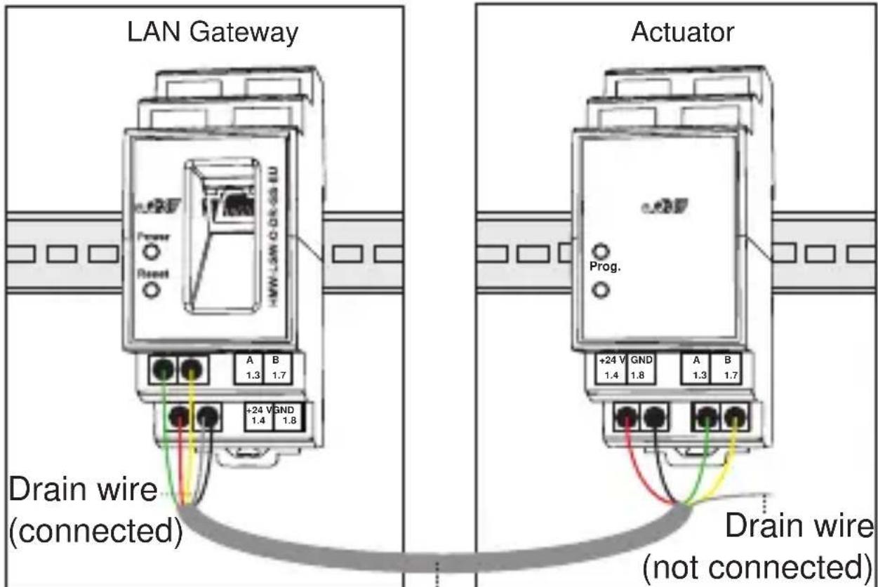
If you are using Homematic wired devices remotely in a sub-distribution board (cable length of the RS485 bus and the 24 V DC cable > 3m), note the following installation requirements:

As soon as the RS485 bus and 24 V DC cables exit the sub-distribution board (cables longer than 3 m), a shielded cable must be used.

Use a shielded telephone cable (min. J-Y(ST)Y 2 x 2 x 0.6, telecommunications installation cable, 4-wire) or network cable (SF/UTP Cat 5e or better).

The shield only has to be connected on one side. Although the shield can be connected on any side, we recommend using the LAN gateway side.

To avoid short-circuits, make sure that the side of the shield or continuity wire which is not connected is made safe or cut back so that it finishes with the cable insulation.
The wire routed in parallel with the shield (continuity wire, see figure below) must be connected to the GND socket of the Homematic wired device.

6.2 Example connection with one sub-distribution board
Main distribution
Shielded cable
Sub-distribution


If there is more than one sub-distribution board, you should make the shield connection separately in each of them, i.e.:
- Incoming shielded cable → Do not connect shield
- Outgoing shielded cable → Shield connected to GND, etc.
6.3 Example connection with more than one sub-distribution board
![graph TD A["Main Gateway"] --> B["Sub-distribution 1"] B --> C["Actuator 1"] C --> D["Switched cable shielded (connected)"] D --> E["Drain wire (connected)"] E --> F["Drain wire (not connected)"] F --> G["Drain wire (not connected) (not connected)"] G --> H["Drain wire 2"] H --> I["Actuator 2"] styl…](/content/2026/05/905653/images/f4c07fee9aef2bf8a36032fa88e5f25bd115944cb323a276a6bf8d424ae72b48.jpg)

The shield must not be connected to the protective conductor of the supply network.
6.4 Connection and installation example

| Terminal Function | |
| 1.3 RS485 | Bus (Bus A) |
| 1.4 Supply | voltage, +24 V |
| 1.7 RS485 | Bus (Bus B) |
| 1.8 Supply | voltage, ground (GND), ground reference for all inputs |
7 Integration into network (LAN)
To establish communication between your Homematic Central Control Unit and the Homematic Wired devices, the Homematic RS485 Gateway has to be integrated into the network. To do this, proceed as follows:
Configuration via Homematic Central Control Unit
- Open the „WebUI“ user interface in your browser.
- In the WebUI, please click „Settings“ → “System control” → „LAN Gateway Settings“.
- In the next window under „General settings“, please click on „Add“.
- In the next window, select the type „Wired: Home-matic Wired RS485 Gateway“. Afterwards, enter the serial number (see sticker on the top of your gate-way) and the security key/password (see sticker on the bottom of your gateway) of your Homematic Wired RS485 Gateway. You can change your settings again later.
- Please confirm with „OK“ and in the next window with „Save“.
• Afterwards, restart your Homematic Central Control Unit. - The Gateway has been integrated successfully into
the network if the status is „Connected“.

To integrate single Homematic Wired devices into your system, please proceed as described in the corresponding operating manuals.

Further information about network problems (e.g. no DHCP) can be found in the FAQs of the website www.homematic.com.
8 Restoring the factory settings
The factory settings of the Homematic RS485 Gateway can be restored manually. If you do this, you will lose all your settings.

Before restoring the factory settings, please delete the device from the user interface WebUI first.
To restore the factory settings, please proceed as follows:
- Press the reset button for approx. 6 seconds. The quickly flashing LED indicates „delete mode“.

- Release the button.
- Press the button again for approx. 3 seconds until the LED flashes very slowly.

- Release the button.
- The LED expires after a short time and the factory settings of the device will be restored.
9 Disassembly
- Before disassembling the Homematic RS485 Gateway, disconnect the wiring.
- Press down the clip at the back of the device with a slotted screwdriver and remove the device from the rail.

10 Maintenance and cleaning
The product does not require any maintenance. Repairs are only to be done by trained professionals.
11 Scope of supply
- Homematic RS485 Gateway (ready for installation)
- Ethernet cable
• Installation and Operating Manual
12 Technical data
Device short name: HMW-LGW-O-DR-GS-EU
Power supply: 24 VDC/SELV
Max. power consumption: 100 mA (max.)
Standby power consumption: 0.75 W
Degree of protection: IP20
Ambient temperature: 0 - 35 °C
Housing dimensions: Standard DIN rail
(W x H x D) housing with
2 units width
35 x 87 x 64 mm
Weight: 76 g
Network: Ethernet, 10/100Base-T
Communication: RS485 Bus
Protection class: III
Subject to technical changes.
Instructions for disposal:

Do not dispose of the device with regular domestic waste. Electronic equipment must be disposed of at local collection points for waste electronic equipment in compliance with the Waste Electrical and Electronic Equipment Directive.

The CE sign is a free trading sign addressed exclusively to the authorities and does not include any warranty of any properties.

For technical support, please contact your specialist dealer.
Manufacturer's authorised representative:

eQ-3 AG
Maiburger Straße 29
26789 Leer / GERMANY
www.eQ-3.de


- TABLE OF CONTENTS
- 1 INFORMATION ABOUT THIS MANUAL
- SYMBOLS USED
- 2 HAZARD INFORMATION
- 3 FUNCTION
- NETWORK INSTALLATION CABLE (DIN RAIL PATCH FIELDS/MODULES)
- POWERLINE COMMUNICATION VIA 230V CABLING (DIN RAIL POWERLINE ADAPTER)
- 4 GENERAL SYSTEM INFORMATION ABOUT HOMEMATIC
- 5 GENERAL INFORMATION ABOUT THE BUS SYSTEM
- 5.1 GENERAL INFORMATION ON THE INSTALLATION
- 5.2 TOPOLOGY OF THE BUS SYSTEM
- 6 INSTALLATION
- CONTACT AN ELECTRICAL INSTALLER
- SPECIALIST KNOWLEDGE REQUIRED FOR INSTALLATION
- FOR INSTALLATION, PLEASE PROCEED AS FOLLOWS
- 6.1 INSTALLATION INSTRUCTIONS FOR REMOTE COMPONENTS
- 6.2 EXAMPLE CONNECTION WITH ONE SUB-DISTRIBUTION BOARD
- 6.3 EXAMPLE CONNECTION WITH MORE THAN ONE SUB-DISTRIBUTION BOARD
- 6.4 CONNECTION AND INSTALLATION EXAMPLE
- 7 INTEGRATION INTO NETWORK (LAN)
- CONFIGURATION VIA HOMEMATIC CENTRAL CONTROL UNIT
- 8 RESTORING THE FACTORY SETTINGS
- 9 DISASSEMBLY
- 10 MAINTENANCE AND CLEANING
- 11 SCOPE OF SUPPLY
- 12 TECHNICAL DATA
- SUBJECT TO TECHNICAL CHANGES
- INSTRUCTIONS FOR DISPOSAL
Brand : Homematic IP
Model : HMW-LGW-O-DR-GS-EU
Category : Home Automation