
HM-PB-2-WM55-2 - Home Automation Homematic IP - Free user manual and instructions
Find the device manual for free HM-PB-2-WM55-2 Homematic IP in PDF.


| Product Type | Wireless Push Button (2-channel) |
| Dimensions (H x W x D) | 55 x 55 x 18 mm |
| Weight | 50 g |
| Power Supply | 1 x CR2032 battery (3V) |
| Battery Life | Up to 2 years (typical use) |
| Radio Protocol | Homematic IP (868 MHz) |
| Range | Max. 100 m in open field |
| Number of Channels | 2 |
| Mounting Type | Wall mount (flush-mount box) |
| Protection Rating | IP20 |
| Operating Temperature | -10°C to +50°C |
| Status LED | Yes (multi-color) |
| Compatible Systems | Homematic IP Access Point required |
| Key Functions | Switch lights, scenes, or other devices |
| Care and Cleaning | Wipe with a dry, soft cloth; no solvents |
| Safety | Observe local electrical regulations; do not open |
| Spare Parts | Replacement battery (CR2032) |
| Repairability | Battery replaceable; other parts not user-serviceable |
| Certification | CE, FCC |
| Color | White |
Frequently Asked Questions - HM-PB-2-WM55-2 Homematic IP
User questions about HM-PB-2-WM55-2 Homematic IP
0 question about this device. Answer the ones you know or ask your own.
Ask a new question about this device
Download the instructions for your Home Automation in PDF format for free! Find your manual HM-PB-2-WM55-2 - Homematic IP and take your electronic device back in hand. On this page are published all the documents necessary for the use of your device. HM-PB-2-WM55-2 by Homematic IP.
USER MANUAL HM-PB-2-WM55-2 Homematic IP
Printed in Hong Kong

Documentation © 2013 eQ-3 Ltd., Hong Kong All rights reserved. No parts of this manual may be reproduced or processed in any form using electronic, mechanical or chemical processes in part or in full without the prior explicit written permission of the publisher.
It is quite possible that this manual has printing errors or defects. The details provided in this manual are checked regularly and corrections are done in the next edition. We do not assume any liability for technical or printing errors.
All registered trade marks and copyrights are acknowledged.
Printed in Hong Kong
We reserve the right to make changes due to technical advancements without prior notice.
131782
V 1.2 (01/2017)
Table of Contents
1 Information concerning these instructions ... 25
2 Hazard information....25
3 Function 26
4 General system information on Homematic. . 29
5 General information on radio operation ..... 29
6 Installation 30
6.1 Scope of delivery 30
6.2 Adhesive strip mounting....31
6.3 Screw mounting 32
6.4 Installation in multiple combinations.....33
7 Start up....34
7.1 Inserting (changing) batteries....34
7.2 Teaching-in....35
7.3 LED flashing sequences and transmission behaviour 39
7.4 Resetting to factory status ..... 40
8 Maintenance and cleaning 41
9 Technical specifications ..... 42
1 Information concerning these instructions
Read these instructions carefully before beginning operation with your Homematic components. Keep the instructions handy for later consultation!
Please hand-over the operating manual as well when you hand-over the device to other persons for use.
Symbols used:

Note! This indicates a hazard.

Note! This section contains additional important information!
2 Hazard information

This device is to be operated indoors only and keep away from the influences of humidity, dust and sunshine or other radiating heat sources.

Using the push button for any purpose other than that described in this operating manual does not fall within the scope of intended use and shall invalidate any warranty or liability. This also applies to any conversion or modification work. This device is intended for private use only.

Do not open the device. It does not contain any parts to be maintained by the user. If an error occurs, please send back the device to the customer service.
3 Function
Homematic push buttons are used to control the receivers that they are taught to work with. A single button can be taught to work with one or more components and address them all simultaneously. That means that pressing a single button can execute many different tasks.
The Homematic push button is battery-operated. As such it is highly flexible where mounting and selecting a mounting location are concerned.
The Homematic push button is mounted and removed very easily using screws or adhesive strips. It is compatible with a number of different surfaces including furniture, brick walls, tiles or glass. Holes or slits do not have to be chiselled out of brick walls. The frame supplied with the device can be used for wall mounting. It is also possible to integrate the Homematic push button into existing switches (see sec. 6.4).
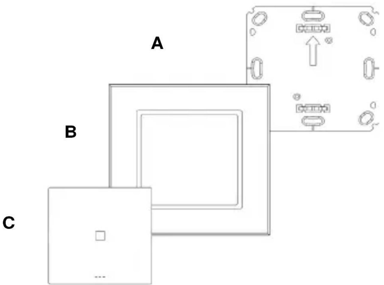
(A) Mounting plate
(B) Attachment frame
(C) Electronic unit/rocker button
4 General system information on Homematic
This device is a part of the Homematic smart home system and works with the bidirectional Homematic wireless protocol.
All devices are delivered in a standard configuration. The functionality of the device can also be configured with a programming device and software. The other resulting functionality and the additional functions that result in the Homematic system in cooperation with other components can be found in the separate configuration instructions or the Homematic System Manual.
All current technical documents and updates are provided under www.Homematic.com.
5 General information on radio operation
The radio transmission is on a non-exclusive transmission path which means that there is a possibility of interference occurring. Other interfering sources can be caused by switching operations, electrical motors or defective electrical devices.
The range of transmission within buildings can greatly deviate from open air distances.
Besides the transmitting power and the reception characteristics of the receiver, environmental influences such as humidity in the vicinity and local structures also play an important role.
Hereby, eQ-3 AG declares that this device conforms with the essential requirements and other installation site as desired conforming with the relevant regulations of directive 1999/5/EG.
The full declaration of conformity is provided under www.Homematic.com.
6 Installation
6.1 Scope of delivery
Push button assembled:
- Mounting plate
- Attachment frame
• Electronic unit with rocker button
Accessories:
- Adhesive strips for wall mount
• 2 wood screws 3.0 x 30 mm
• 2 wall anchors 5 mm
• 2 LR03 batteries (micro/AAA/LR03)
You can either use screws or adhesive strips to mount the Homematic push button to a wall in the frame supplied or integrate it into an existing switch (see sec. 6.4 for suitable switches).
6.2 Adhesive strip mounting
- Choose a site for installation. The surface on which you are mounting the push button must be clean, dry and greaseless.
- For mounting of the assembled push button, attach the adhesive strips to the back side of the mounting plate. You should be able to read the letters on the back side (according to figure).

- Remove the protective film from the adhesive strip.
- Press the assembled push button with the back side to the wall in the position where it should subsequently be attached.
6.3 Screw mounting
- Choose a site for installation.
- Make sure that electrical lines in the wall will not be damaged.
- Position the mounting plate on the desired site on the wall. Make sure that the arrow on the mounting plate is pointing upwards.
- Use a pen to mark the positions of 2 bore holes A (diagonally opposite) in the mounting plate on the wall. The bore holes B can be used for installation with a flush-mounting box.
![graph TD A["Component A"] --> B1["Component B"] A --> B2["Component B"] A --> B3["Component B"] B1 --> B4["Component B"] B2 --> B5["Component B"] B3 --> B6["Component B"] style A fill:#f9f,stroke:#333 style B fill:#ccf,stroke:#333 style B1 fill:#cfc,stroke:#333 style B2 fill:#cfc,stroke:#333 style B…](/content/2026/05/905635/images/c08a39d2d3af2a2baeb746e4010db9568872f67be6bc64825eeaa3a23fc3c59f.jpg)
- If you are working with a stone wall, drill the marked two 5 mm holes and insert the plugs supplied. If you are working with a wooden wall, you can pre-drill 1.5 mm holes to make screws easier to insert.
- Use the screws and plugs supplied to fasten the mounting plate to the wall.
- Next, attach the frame to the mounting plate.
- Attach the push button. Make sure that the arrows on the back side point upwards and that the clips on the mounting plate latch into the openings on the electronic unit.
6.4 Installation in multiple combinations
You can mount the push button with the attachment frame provided or use it with frames of other manufacturers as well as integrate the electronic unit into a multi-gang frame. In both cases, mounting with adhesive strips and screws is possible. For mounting with multiple combinations, make sure that the mounting plate of the push button is seamlessly aligned to the already fixed mounting plate/retaining ring.
The Homematic push button is designed to fit into frames supplied by the following manufacturers:
| Manufacturer Frame | |
| Berker S.1, B.1, B.3, | B.7 Glas |
| ELSO Joy | |
| GIRA System 55, St | standard 55, E2, E22, Event, Espirit |
| merten 1-M, Atelier- | M, M-Smart, M-Arc, M-Star, M-Plan |
| JUNG A 500, AS 500 | A plus, A creation |
7 Start up
7.1 Inserting (changing) batteries
- Once mounted, the electronic unit can easily be pulled out of the frame. To remove the electronic unit from the frame, take hold of the sides of the electronic unit and pull it out. You do not need to remove the rocker button or open the device.
- Turn the electronic unit over to remove or insert the batteries according to the illustration. - After removing the old batteries, please wait approx. 10 seconds before inserting the new ones.
- Put the electronic unit back into the frame.
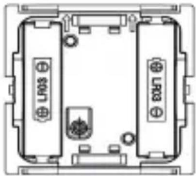

Never recharge standard batteries. Doing so will present a risk of explosion. Do not throw the batteries into a fire. Do not short-circuit batteries.

Used batteries should not be disposed of with regular domestic waste. Instead, take them to your local battery disposal point.
7.2 Teaching-in

Please read this section completely before starting with any teaching!

Before being able to use your device with QIVICON, it has to be taught-in to your QIVICON Home Base.
Therefore, please log-in to „My QIVICON“ at www.qivicon.com/login. There, please select „Add device“ and follow the instructions.
To enable radio components to communicate, they need to be taught-in to one another. To control the Homematic actuators with the push button, proceed as follows:
The push button supports three different modes:
- Teach mode (teaching HomeMatic components)
- Configuration mode (for changing push button parameters)
• Operation mode (normal operation)
Teaching requires that both devices to be connected are put into teach mode. Please see the corresponding manual of the actuator for instructions how to put the device into teach mode.
- The push button is put into teach mode with the teach button A.
- The teach button A can be found on the back side of the electronic unit.
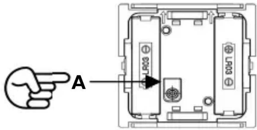
- To reach the teach button, you have to hold both sides of the electronic unit and pull it out of the frame.
- Keep a distance of approx. 1 m between the push
button and the actuator.
- The push button and the actuator have to be put into teach mode at the same time:
- Keep the push button on both sides of the rocker. Press the teach button A shortly. The configuration mode is indicated with a flashing green device LED.
- Turn the electronic unit to the front side (see illustration). The arrow on the mounting plate should point upwards. Press the rocker button shortly.

• The device LED flashes orange.
- Now, the actuator has to be put into teach mode.
- If teaching of rocker buttons is successful, it is indicated with an illuminated green LED.
- The lower rocker button is defined for the instructions OFF, DOWN or DARKER and the upper rocker button for the instructions ON, UP or
BRIGHTER. Dimming occurs by holding the button pressed.
- If you want to exit configuration mode, press the teach button again.

If no teaching occurs, teach mode is automatically ended after 20 seconds. If another device is in teach mode, this is taught. If the push button is already taught for a center and therefore is blocked for direct training, it can still be put in configuration mode as described above, the device LED is illuminated in red for 2 seconds after pressing an operating button however. Direct teaching is not possible!
After teaching, in the operation mode simple operating functions are available. The 2 buttons (on a common rocker) can be controlled by pressing up or down (▼) shortly. Pressing up (▲triggers the functions ON, UP or BRIGHTER, pressing down
(▼) triggers the functions OFF, DOWN or DARKER. Switch actuators and dimmers can then be switched ON/OFF. Furthermore, dimming occurs by holding the button pressed and blind actuators move up or down.
7.3 LED flashing sequences and transmission behaviour
The LED's flashing sequences have different meanings:
| Flashing sequence Meaning | |
| Min. 2s green LED Teaching | g successful |
| 2s red LED Teaching failed | |
| Orange flashing Only rocker | r button in teach mode |
| Brief orange flashing and 2s red or green (depending upon success) | Other device in teach mode and rocker button put in teach mode |
| Short orange/short green flashing | Signal is being send/confirmed |
| Push button in configuration mode and illuminated red with button actuation | Push button already taught for center and is therefore blocked from direct teaching |
7.4 Resetting to factory status
Hold the teach button A down for at least 5s.

The device LED starts to flash slowly in red.
To reset the device, release the teach button briefly and press it again for at least 5s.
The LED starts to flash in red faster while the button is held down.
Releasing the teach button completes the reset procedure and the LED is illuminated red for approx. 3s to confirm the reset operation.
If you want to abort the reset procedure, you can press the teach button briefly again or wait 15s. In either case, the flashing red will stop.
Possible error messages:
If the LED does not start flashing after holding the button down for 5s but is illuminated continuously, the
device cannot be reset! In this case, the encoding is active using a system security key that differs from the key delivered with the system. In order to reset the device, you must use the configuration software of the center for resetting! The procedure is described in the center software instructions. (This error can occur only if you have a center and have taught the device for this center.)
8 Maintenance and cleaning
This product is maintenance-free besides possibly requiring a battery change. Maintenance or repairs are only to be done by trained professionals. Clean the products using a soft, clean, dry and lint-free cloth. To remove heavier contamination, make cloth damp with lukewarm water. Cleaning agents that contain solvents are not to be used because they can harm the plastic housing and the labels.
9 Technical specifications
Short name: HM-PB-2-WM55-2
Radio frequency: 868.3 MHz
Typ. outdoor range: 100 m
Batteries: 2xLR03 / Micro/AAA
Power supply: 3 V
Battery lifespan: .... up to 5 years
Dimensions: 86 x 86 x 16.5 mm
(H x W x D)
Subject to technical changes.
Instructions for disposal:

Do not dispose off the device as part of household garbage! Electronic devices are to be disposed off in accordance with the guidelines concerning electrical and electronic devices via the local collecting point for old electronic devices.

The CE sign is a free trading sign addressed exclusively to the authorities and does not include any warranty of any properties.
Manufacturer's authorised representative:

eQ-3 AG
Maiburger Straße 29
26789 Leer / GERMANY
www.eQ-3.de


- TABLE OF CONTENTS
- 1 INFORMATION CONCERNING THESE INSTRUCTIONS
- SYMBOLS USED
- 2 HAZARD INFORMATION
- 3 FUNCTION
- 4 GENERAL SYSTEM INFORMATION ON HOMEMATIC
- 5 GENERAL INFORMATION ON RADIO OPERATION
- 6 INSTALLATION
- 6.1 SCOPE OF DELIVERY
- 6.2 ADHESIVE STRIP MOUNTING
- 6.3 SCREW MOUNTING
- 6.4 INSTALLATION IN MULTIPLE COMBINATIONS
- 7 START UP
- 7.1 INSERTING (CHANGING) BATTERIES
- 7.2 TEACHING-IN
- 7.3 LED FLASHING SEQUENCES AND TRANSMISSION BEHAVIOUR
- 7.4 RESETTING TO FACTORY STATUS
- POSSIBLE ERROR MESSAGES
- 8 MAINTENANCE AND CLEANING
- 9 TECHNICAL SPECIFICATIONS
- SUBJECT TO TECHNICAL CHANGES
- INSTRUCTIONS FOR DISPOSAL
Brand : Homematic IP
Model : HM-PB-2-WM55-2
Category : Home Automation