
HM-LC-Sw4-DR - Home Automation Homematic IP - Free user manual and instructions
Find the device manual for free HM-LC-Sw4-DR Homematic IP in PDF.


| Product Type | Wireless Switch Actuator 4-channel |
| Dimensions (W x H x D) | 51 x 51 x 35 mm |
| Weight | 45 g |
| Power Supply | 230 V AC / 50 Hz |
| Max. Switching Current | 16 A per channel (resistive load) |
| Radio Protocol | Homematic IP (868.3 MHz) |
| Range (free field) | Up to 200 m |
| Number of Channels | 4 |
| Installation Type | Flush-mounted (switch box) |
| Degree of Protection | IP20 |
| Operating Temperature | -5 °C to +40 °C |
| Functions | Switching, time-delay, staircase lighting timer, status feedback |
| Maintenance | No regular maintenance required; keep dry and dust-free |
| Cleaning | Wipe with a dry cloth – do not use solvents |
| Safety Notes | Installation by qualified electrician only; disconnect power before installation |
| Spare Parts / Repairability | Not user-serviceable; replace device if defective |
| General Information | Part of the Homematic IP smart home system; requires Homematic IP access point |
Frequently Asked Questions - HM-LC-Sw4-DR Homematic IP
User questions about HM-LC-Sw4-DR Homematic IP
0 question about this device. Answer the ones you know or ask your own.
Ask a new question about this device
Download the instructions for your Home Automation in PDF format for free! Find your manual HM-LC-Sw4-DR - Homematic IP and take your electronic device back in hand. On this page are published all the documents necessary for the use of your device. HM-LC-Sw4-DR by Homematic IP.
USER MANUAL HM-LC-Sw4-DR Homematic IP
Radio-controlled switch actuator 4-channel, for mounting on DIN rails: HM-LC-Sw4-DR
1. 1st English edition 08/2010
Documentation © 2010 eQ-3 Ltd., Hong Kong All rights reserved. This manual may not be reproduced in any format, either in whole or in part, nor may it be duplicated or edited by electronic, mechanical or chemical means, without the written consent of the publisher.
Typographical and printing errors cannot be excluded. However, the information contained in this manual is reviewed on a regular basis and any necessary corrections will be implemented in the next edition. We accept no liability for technical or typographical errors or the consequences thereof.
All trademarks and industrial property rights are acknowledged.
Printed in Hong Kong.
Changes may be made without prior notice as a result of technical advances.
91751 / V 1.1
Table of contents
1 Information about this manual ..... 2 4
2 Hazard information 24
3 Function....27
4 General system information about HomeMatic 29
5 General information about radio operation . 29
6 Installation 31
7 Start-up 34
7.1 Simple operator functions using integrated buttons....34
7.2 Teaching-in 35
8 Operation....36
9 Resetting to the initial state ..... 3 6
10 Device LED feedback ..... 3 7
10.1 Flashing codes 37
10.2 Operating status display.... 37
11 Response to power recovery ..... 3 8
12 Maintenance and cleaning 38
13 Technical data....39
1 Information about this manual
Read this manual carefully before starting to use your device.
Keep the manual so you can refer to it at a later date should you need to.
If you hand over the device to other persons for use, please hand over the operating manual as well.

Attention!
This indicates a hazard.

Note. This section contains important additional information!
2 Hazard information

The actuator that is described is part of a building installation. When planning and setting up electrical installations, the standards and guidelines which are applicable in the country in which the equipment is installed must be complied with.
The device has been designed solely for operation on a 230 V/50 Hz AC supply. Only qualified electricians (to VDE 0100) are permitted to carry out work on the 230 V mains. Applicable accident prevention regulations must be complied with whilst such work is being carried out.
To avoid electric shock, disconnect the mains voltage prior to starting work on the device (trip the miniature circuit-breaker). Noncompliance with the installation instructions can cause fire or introduce other hazards.
The device may only be operated indoors and must be protected from the effects of damp and dust, as well as solar or other methods of heat radiation. Using this device for any purpose other than that described in this operating manual does not fall within the scope of intended use and shall invalidate any warranty or liability.
Do not exceed the capacity specified for the device. If this capacity is exceed, this could lead to the destruction of the device, to a fire or to an electrical accident.

The device has not been designed to support safety disconnection.

Do not open the device: it does not contain any components that need to be serviced by the user. There is a risk of electric shock if the device is opened. In the event of an error, please return the device to our service department.

When connecting to the device terminals, take the permissible cables and cable cross sections into account.

It is absolutely essential to take the technical data (in particular the maximum permissible switching capacity of the relay and the type of load to be connected) into account before connecting a load. All load data relates to resistive loads.

Refer to the relevant installation regulations when performing installations in distribution systems.
3 Function
The actuator switches up to 4 connected consumers with total switching capacity of 5750 VA (230 V/25 A) or 3680 VA (230 V/16 A) per channel on the basis of received radio commands. Commands are transmitted by actuating buttons or remote controls, or via a software interface. It is also possible to control actuators via taught-in sensors. When an event occurs, the sensors transmit a command (in the same way as a button). Refer to the manual for the corresponding sensor for more detailed information.
Mounted on a standard DIN rail within distribution boards.
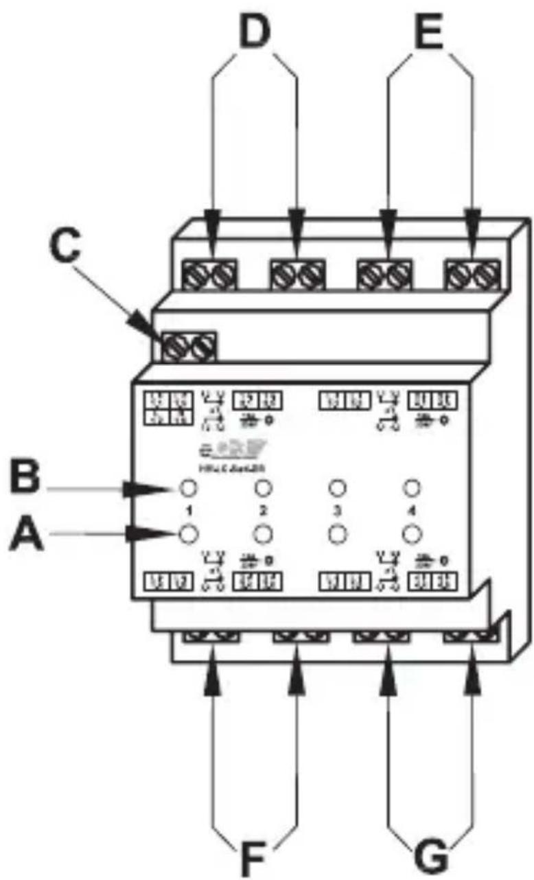
(A) Channel button, channel 1 ... 4
(B) Channel LED, channel 1 ... 4
(C) Power supply, 230 V
(D) Switching channel 1
(E) Switching channel 2
(F) Switching channel 3
(G) Switching channel 4
4 General system information about HomeMatic
This device is part of the HomeMatic home control system and works with the bi-directional BidCoS® wireless protocol. All devices are delivered in a standard configuration. The functionality of the device can also be configured with a programming device and software. The additional functions that can be made available in this way and the supplementary functions provided by the HomeMatic system when it is combined with other components are described in the HomeMatic System Manual.
All current technical documents and updates are provided at www.HomeMatic.com.
5 General information about radio operation
Radio transmission is performed on a non-exclusive transmission path, which means that there is a possibility of interference occurring.
Interference can also be caused by switching operations, electrical motors or defective electrical devices.

The range of transmission within buildings can differ greatly from that available in the open air. Besides the transmitting power and the reception characteristics of the receiver, environmental factors such as humidity in the vicinity have an important role to play, as do on-site structural/screening conditions.
eQ-3 Entwicklung GmbH hereby declares that this device conforms with the essential requirements and other relevant regulations of Directive 1999/5/EC.
You can find the full declaration of conformity at www.HomeMatic.com.
6 Installation

Refer to the relevant installation regulations when performing installations in distribution systems.
Place the switching module onto the DIN rail and lock it in position.

Make sure that the locating springs engage properly and that the device is securely seated on the rail.
Strip 8 mm from the ends of the power supply cable and the cables to the loads, without damaging the exposed wires. Observe the permissible cable cross sections.
Wire the power supply connection and the load connections to the 230 V mains voltage in accordance with the connection diagram on the following page.

Make sure that all connections are tight and secured in the installation terminals.
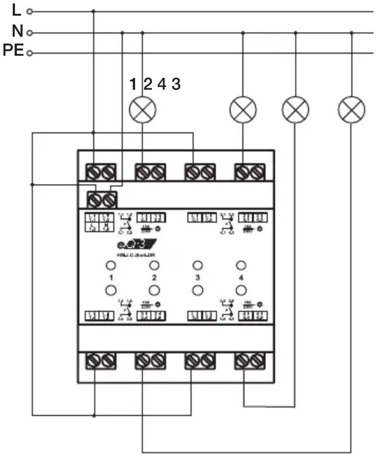
| Terminal Function | |
| 1.2 Power | supply (phase conductor) |
| 1.6 Power | supply (neutral conductor) |
| 1.1, 1.5 | Phase conductor connection, channel 1 |
| 2.1, 2.5 Switched phase channel 1 | |
| 3.1, 3.5 | Phase conductor connection, channel 2 |
| 4.1, 4.5 Switched phase channel 2 | |
| 1.4, 1.8 | Phase conductor connection, channel 3 |
| 2.4, 2.8 Switched phase channel 3 | |
| 3.4, 3.8 | Phase conductor connection, channel 4 |
| 4.4, 4.8 Switched phase channel 4 | |
The switching channels have potential-free relay contacts.

The total connected load of all channels must not exceed 25 A.
Permitted cable cross sections for connecting to the actuator:
| Rigid cable [mm2] | Flexible cable with ferrule [mm2] |
| 0.14 – 2.50 0.14 | -1.50 |
7 Start-up
7.1 Simple operator functions using integrated buttons
The device features one control button per channel. You can operate the actuator by means of these buttons immediately (no teaching-in required) and check that the electrical installation has been performed correctly.

Simply press and release the button to operate the actuator. Pressing and holding down the button (for more than 4 seconds) will switch the relevant channel of the actuator to teach-in mode.
The relevant channel LED signals the switching status of the relay:
LED on - relay contact enabled
LED off - relay contact disabled
7.2 Teaching-in
Please read this entire section before starting the teach-in procedure.
To execute the teach-in procedure, both of the devices to be connected must be in teach-in mode. The required switching actuator channel must also be selected.
When teaching in at a central control unit, any channel can be selected.
To teach in, proceed as follows.
- Press the required channel button for about 4 seconds.
If the respective channel LED flashes continuously, this signals that teach-in mode is active. - Now put the second device into teach-in mode, for more information see the operating instructions of the relevant device.
- If another HomeMatic device is also in teach-in mode, this is taught in on the selected switching actuator channel.
If no teach-in operations are carried out, teach-in mode will be exited automatically after 20 seconds.
8 Operation
After teach-in has been performed, simple operator functions are available via the taught-in control elements. Depending on the taught-in control element, the switch actuator can be controlled by means of an ON/OFF pair of buttons or by toggling, e.g. just a single button on an appropriately programmed remote control.
9 Resetting to the initial state
To reset the actuator to the initial state, put the device into teach-in mode using the first channel button (hold it down for at least four seconds). If the device is in teach-in mode, hold the first channel button down for at least four seconds again. If the device LED flashes quickly, this indicates that the actuator is being reset.
10 Device LED feedback
10.1 Flashing codes
Various actuator states are indicated by the channel LEDs flashing:
| Slow flashing Teach-in mode | |
| Fast flashing Reset | |
| One long flash, n brief flashes (depending on the type of error) | Error |
10.2 Operating status display
As soon as a channel's relay is picked up (i.e. switched on), the corresponding channel LED lights up continuously.
Once the actuator has been configured via the central control unit or a programming tool, the device LED will indicate other device states in addition to those already described.
11 Response to power recovery
When the operating voltage is switched on (recovery of mains voltage), the actuator checks its components. If an error is detected, all channel LEDs will flash. This is repeated continuously and the device does not perform its function. If the test is completed without errors, the actuator transmits a wireless telegram containing its status information. To prevent all actuators from transmitting at the same time when power is recovered (after a mains power failure or a disconnection, for example), there is a random delay before the actuator transmits. During this time, the channel LEDs flash (as in teach-in mode). If the delay is very short, this flashing may be almost imperceptible.
12 Maintenance and cleaning
The product does not require any maintenance. Enlist the help of an expert to carry out any repairs.
13 Technical data
Radio frequency: 868.3 MHz
Typ. open air range: 100 m
Power supply: 230 V/50 Hz
Standby consumption: 0.5 W
Degree of protection: IP20
Protection class: II
Outputs: 4 potential-free relay
switch outputs
Switching capacity: 230 V 50 Hz / 16 A (per
relay, resistive load);
Max. total for all
channels 25 A
Dimensions: Standard DIN
(W x H x D) rail housing, 4 WM
72 x 65 x 87 mm

Instructions for disposal
Do not dispose of the device with regular domestic waste. Electronic equipment must be disposed of at local collection points for waste electronic equipment in compliance with the Waste Electrical and Electronic Equipment Directive.

The CE Marking is simply an official symbol relating to the free movement of a product; it does not warrant a product's characteristics.

eQ-3 AG
Maiburger Straße 29
D-26789 Leer
www.eQ-3.com


- 1ST ENGLISH EDITION 08/2010
- TABLE OF CONTENTS
- 1 INFORMATION ABOUT THIS MANUAL
- 2 HAZARD INFORMATION
- 3 FUNCTION
- 4 GENERAL SYSTEM INFORMATION ABOUT HOMEMATIC
- 5 GENERAL INFORMATION ABOUT RADIO OPERATION
- 6 INSTALLATION
- 7 START-UP
- 7.1 SIMPLE OPERATOR FUNCTIONS USING INTEGRATED BUTTONS
- 7.2 TEACHING-IN
- 8 OPERATION
- 9 RESETTING TO THE INITIAL STATE
- 10 DEVICE LED FEEDBACK
- 10.1 FLASHING CODES
- 10.2 OPERATING STATUS DISPLAY
- 11 RESPONSE TO POWER RECOVERY
- 12 MAINTENANCE AND CLEANING
- 13 TECHNICAL DATA
- INSTRUCTIONS FOR DISPOSAL
Brand : Homematic IP
Model : HM-LC-Sw4-DR
Category : Home Automation