
IK1 - Remote control DANFOSS - Free user manual and instructions
Find the device manual for free IK1 DANFOSS in PDF.


| Product Type | Remote Control |
| Brand | Danfoss |
| Model | IK1 |
| Dimensions (H x W x D) | 85 x 85 x 20 mm |
| Weight | 45 g (without batteries) |
| Power Supply | 2 x AAA alkaline batteries |
| Battery Life | Approximately 2 years under normal use |
| Radio Frequency | 868 MHz (European frequency band) |
| Maximum Range | 30 meters in open space |
| Operating Temperature Range | 0°C to +40°C |
| Storage Temperature Range | -20°C to +65°C |
| Protection Class | IP20 (indoor use only) |
| Primary Functions | On/Off, Temperature set, Boost mode, Away mode, Lock function |
| Display Type | LCD with backlight |
| Compatibility | Danfoss Living Connect series thermostats and receivers |
| Mounting | Handheld or wall mount (bracket included) |
| Cleaning Instructions | Wipe with a soft, dry cloth. Do not use any cleaning agents. |
| Safety Features | Battery low indicator, child lock, automatic shut-off (configurable) |
| Spare Parts Availability | Battery cover, wall bracket (order from Danfoss support) |
| Repairability | Battery replacement only; no user-serviceable parts inside. Contact authorized service for repairs. |
Frequently Asked Questions - IK1 DANFOSS
User questions about IK1 DANFOSS
0 question about this device. Answer the ones you know or ask your own.
Ask a new question about this device
Download the instructions for your Remote control in PDF format for free! Find your manual IK1 - DANFOSS and take your electronic device back in hand. On this page are published all the documents necessary for the use of your device. IK1 by DANFOSS.
USER MANUAL IK1 DANFOSS
natural_image
Two black industrial control modules with digital displays and red trim, no visible text or symbolsRevision history Table of revisions
| Date Changed Rev | ||
| June 2024 Updated cover art, ingress protection rating 0102 | ||
| March 2024 Initial Release 0101 | ||
Contents
Safety instructions
FCC rules....4
General safety....4
IK1 Safety Warnings....5
Technical description
IK1 Dimensions and Identification....6
IK1 Transmitter Start up....7
IK1 Detailed description....8
IK1 Model code creation....8
Pistol Grip Docking Station....9
Default IK1 Layouts....9
Maintenance
Maintenance tips....10
Troubleshooting 2.4GHz....10
Charger and battery
Transmitter Power supply....12
Alkaline Battery Recommendations....12
Charger and battery....12
BC70K and BT11K specifications....13
BC70K Battery Charger Set-up....13
BC70K Charger LEDs Status 14
Battery Charging Recommendations....14
BC70K Battery Charger Dimensions....15
Safety instructions
FCC rules
This equipment has been tested and found to comply with the limits for a Class A digital device, pursuant to Part 15 of the FCC Rules.
Changes or modifications not expressly approved by the manufacturer can void the user's authority to operate the equipment.
To comply with FCC RF exposure compliance requirements, this device and its antenna must not be collocated with, or operating in conjunction with, any other antenna or transmitter, may not cause harmful interference, and must accept any interference received, including interference that may cause undesired operation.
The limits are designed to provide reasonable protection against harmful interference when the equipment is operated in a commercial environment. This equipment generates, uses, and can radiate radio frequency energy, and if not installed and used in accordance with the instruction manual, may cause harmful interference to radio communications.
Operation of this equipment in a residential area is likely to cause harmful interference in which case the user will be required to correct the interference at his own expense.

Warning
IK1-G General Safety
The following safety instructions must be read carefully to install and use the product properly, and to keep it in perfect working condition, and to reduce the risk of miss use.
- Danfoss recommends the use of ESD PPEs (electrostactic discharge personal protection equipment).
- Strictly adhere to the installation instructions contained in this document.
• Make sure that professional and competent personnel carry out the installation.
• Ensure that all on site and prevailing safety regulations are fully respected.
- The Electrical Installation where it may be connected, The receiver may be connected through an automatic magneto thermic switch (with omnipolar cut capacitance: F+N) and differential with characteristics according to the Low Voltage Recommendations.
• Make sure that this document is permanently available to the operator and maintenance personnel.
- Keep the transmitter out of reach of non-authorized personnel.
- Remove the transmitter key when the set is not in use.
- Check each working day the STOP button and other safety features. When in doubt, press the STOP button.
- Whenever several sets have been installed, make sure the transmitter is the right one. Identify the machine controlled on the label for this purpose on the transmitter or by using the display (in case it does have one).
• Service the equipment periodically.
- Avoid High Pressure water Spraying to Receivers while cleaning the machine
- When carrying out repairs, use spare parts supplied by Danfoss only.
Safety instructions

Warning
Potential damage to the operator or the product. Do not use this product on machines in potentially explosive atmospheres unless the model is ATEX/RATEX certified to work in such conditions.
IK1 Safety Warnings
Potential damage to operator and product.
Follow the guidelines below to reduce risk of injury to the operator and the product.
Neodimium Magnet on Handle lower Part.
Beware Users with Pacemakers to avoid approaching the device to the chest.
• Use the device with the manufacturer's battery and battery charger (if applicable).
• Only allow qualified personnel to operate the equipment.
• Always set the STOP button in the off position when not in use.
• Always press STOP before plugging in tether cable (if applicable).
- Remove the Tether connection on the transmitter First (if applicable).
- Do not operate product when visibility is limited.
• Make sure product is compatible with the machine.
- Avoid knocking or dropping the product.
• Do not use the product if a failure is detected.
Changes or modifications not approved by Danfoss can void the user's authority to operate this product.
Quick reference precautions
natural_image
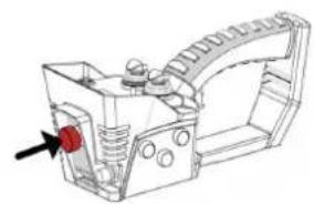
Technical line drawing of a mechanical component with no visible text or symbolsPress the STOP button when transmitter is not being used
natural_image
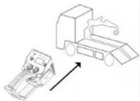
Illustration of a truck and a mechanical device with an upward arrow (no text or symbols)Make sure the transmitter Works with the desired machine

natural_image
Technical line drawing of a mechanical component with a red arrow pointing to a specific part (no text or symbols present)After use, press the STOP Button

natural_image
Illustration of a stylized eye and a camera with a light beam, no text or symbols presentDo not use the Device when visibility is limited
natural_image
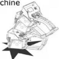
Illustration of a mechanical device with star-shaped base (no text or symbols)Avoid Knocking or Dropping the Device
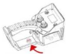
Careful. Magnet on the Handle Lower part.
Technical description
IK1 Dimensions and Identification
The illustration below details dimensions and features of the IK1-G transmitter.
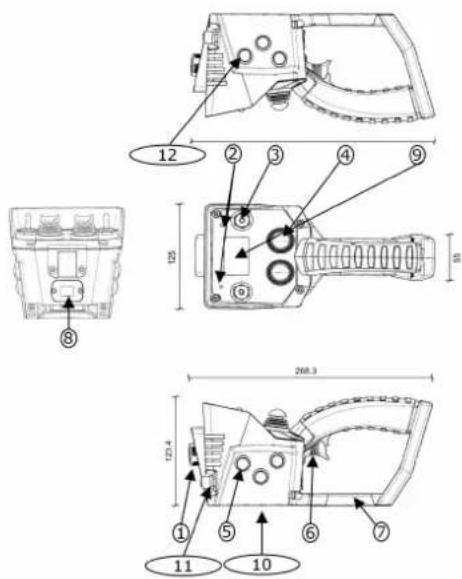
Dimensions in mm.
The illustration below details dimensions and features of the IK1 transmitter.
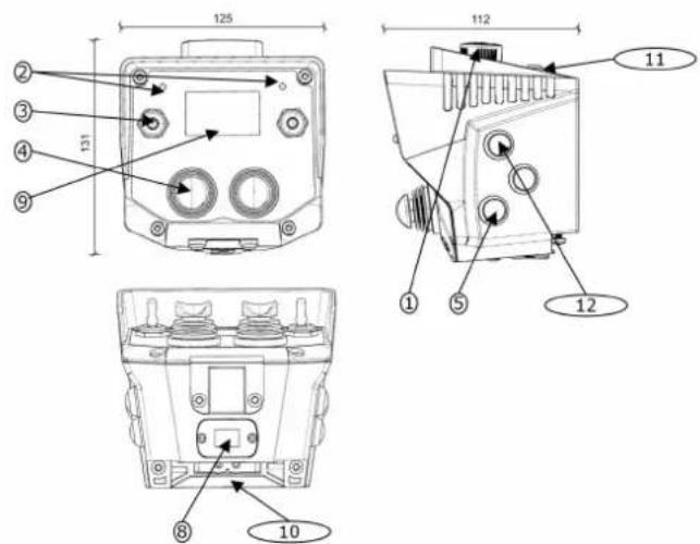
1.- STOP Button
2. Status LEDs (2)
3. Toggle Switches
4. Thumb Joysticks
5. Side Pushbuttons (up to 5)
6. Proportional Trigger
7. Internal Magnet
Technical description
- External and extractable EEPROM module
- LCD Display
- Alkaline Battery Pack (4xAA) or Rechargeable BT11K Battery
- Tether Connector
- START Button
IK1 Transmitter Start up
In order to turn the transmitter ON (OPERATION mode), please follow these steps:
Start up the device
- Place a charged Lilon battery or Alkaline Battery Pack (4xAA Batteries) on the transmitter. Li Ion Batteries BT11K must be charged following the instructions of the Battery Charger.
- Push and pull out the STOP button.
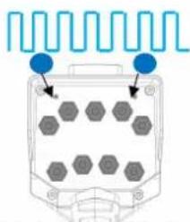
LED status (blue)
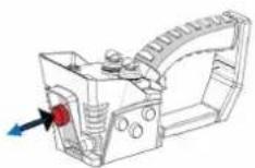
Press and Release the STOP button.
natural_image
Diagram of an electronic device with hexagonal components and signal waveforms (no text or symbols)Status LEDs Blinking BLUE
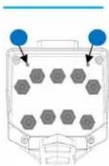
Status LEDs solid BLUE
LED will flash, blinking blue until it reaches the Stand-by mode (fixed blue). If the transmitter includes a Display, it will display the identification of the machine, as well as the battery level, if it has been pre-programmed.
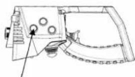
- Press the START button, and wait for the status LED to turn to fixed green.
LED status (green)
natural_image
Technical line drawing of a mechanical component with circular features and a pointer indicating a specific point (no text or symbols present)Press START Button
natural_image
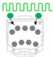
Diagram of an analog oscilloscope with hexagonal grid and green signal wave indicator (no text or labels)Status LEDs Blinking GREEN
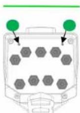
Status LEDs solid GREEN
The status LED will start blinking green, meaning the transmitter is trying to connect with the receiver. Once the Tx is linked, LED will turn to fixed green.
- Press any of the transmitter's maneuver buttons and its corresponding relay will be activated.
- Check to make sure all the maneuvers work in a coherent way with the expected movements by checking the supplied production sheet, included with the system.
Technical description
IK1 Detailed description
| Description Value | ||
| Stop Function (2.4 GHz) Cat3 - PLe | ||
| Ingress Protection rating IP66/NEMA4 | ||
| Anti-condensation system Goretex Film | ||
| Frequency band - ERP 2405MHz to 2475MHz ; ERP 20dBm/100mW | ||
| Range Line of sight (guaranteed) 100m | ||
| Main mechanisms (maximum number) | Thumb Joysticks (2) | |
| Auxiliary mechanisms up to 9 toggle switches | ||
| Side Buttons up to 6 buttons | ||
| Trigger (with Pistol Grip) Proportional Trigger | ||
| Removable EEPROM External | ||
| Battery model Alkaline Battery Pack (4xAA Batteries) BT11K | ||
| Battery life 15 - 24 hours 7 - 11 hours | ||
| Response Time 100ms | ||
| Operating temperature range -20 °C to 70 °C (-4 °F to 158 °F) | ||
| Storage Temperature Range (24h) -25°C to 75°C (-13°F to 167°F) | ||
| Storage Temperature Range (long periods) | -25°C to 55°C (-13°F to 131°F) | |
| Relative Humidity | max. 95% without condensation | |
| Weight (with battery) | 800 grams | |
| Dimensions LxWxH mm | 268.3 x 125 x 123.4 | |
| Harness | magnets on grip to stick on metallic surfaces | |
| Available Options | ||
| Display | 128x64 Graphic LCD | |
| LED Panel | na | |
| Tether connector | Yes (M12 Connector) | |
| Range limiter | na | |
| Associated receivers (2.4GHz) | MP08, MPCAN, MP20, R11, R13F | |
IK1 Model code creation
The model code generation is based on a model code:
- Family: IK1
- Variant: G Pistol Grip, B Console Box
- Power Supply: 1: Alkaline Batteries, 2: NiMH Rechargeable Batteries, 3: Li-Ion Rechargeable Batteries
- Charging Type: N: No Charger, D: Docking Station, C: Battery Charge
Example:
IK1 - G1N (with Pistol Grip, alkaline batteries and no charger)
IK1 - G3C (with Pistol Grip, Li-Ion battery and BC70 charger)
IK1 - G3D (with Pistol Grip, Li-Ion battery and Docking station)
IK1 - B1N (console Box Style, alkaline batteries and no charger)
Technical description
Pistol Grip Docking Station
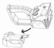
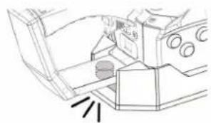
As an option there is the possibility of adding a Pistol Grip Docking Station. The way to lock and unlock the Pistol grip is as follows:
natural_image
Technical line drawing of a mechanical component with an arrow indicating assembly or transformation (no text or symbols present)1.- Slide Pistol Grip into Docking Station
natural_image
Technical line drawing of a mechanical assembly with no visible text or symbols2.- The Pistol Grip magnet locks with the docking base.
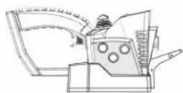
3.-Locked Position
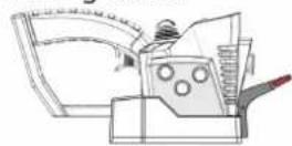
4.- To unlock the Pistol Grip Press the tab.
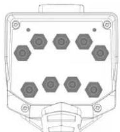
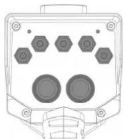
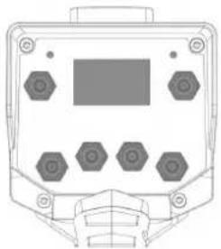
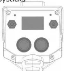
Default IK1 Layouts
natural_image
Front view of a mechanical component with hexagonal holes and mounting brackets (no text or symbols)Up to 9 Toggle Switches or buttons
natural_image
Front view of a mechanical or electronic device with hexagonal components and mounting holes (no text or symbols visible)Up to 5 Toggle Switches + 2 Thumb Joysticks
natural_image
Front view of a control panel with hexagonal buttons and a central display (no text or symbols)Up to 6 Toggle Switches + LCD Display
natural_image
Front view of a control panel with display and buttons (no text or symbols visible)2 Toggle Switches + 2 Thumb Joysticks + LCD Display
Maintenance
IK1-G maintenance tips
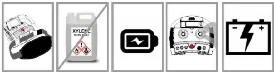
This product is designed for use in an industrial environment that may shorten the product's lifespan. Use these tips to maximize the lifespan of the product.
- Use the hook/Shoulder strap/Belt provided with the transmitter to prevent the transmitter from falling
- Do not clean the transmitter with solvents or pressurized water; use a damp cloth or soft brush for cleaning it.
• If the Mechanisms show signs of deterioration, contact the Authorized Technical Service for repair. - Check the battery contacts are clean and battery is inserted correctly.
- Ensure that the product is supplied with Rechargeable batteries.
- Be sure to recharge or replace battery regularly.
Maintenance tips quick reference
Troubleshooting 2.4GHz
| Status LED (on all Transmitters) Display | Message | Description Action | ||
| Color and frequency Pulse frequency | ||||
| Blue | fast pulses Starting the | system | Starting the system; establishing communications with radio and EEPROM | Wait | |
| Blue | continuous Stand-by | mode | Standby mode. Set up system, waiting user's action | Press START to enter operation mode | |
| Green | fast pulses Attempting to link with the receiver and | waiting its answer | Wait | ||
| Green | continuous | Working Operate | |||
| Green | slow pulses Standby; no action has been taken for | some time | Press START to return to operation mode | ||
| Red | slow pulses | EEPROM module missing or corrupt Check | EEPROM and reprogram if necessary | ||
| Red | double pulses | Radio error; radio communications error | Replace transmitter | ||
| Red | 3 pulses Display Error. Display communication | Error | Replace Display or Transmitter | ||
| Red | 4 pulses | Multikey Error. Multikey not in ON position or Broken. | Check Multikey or Replace it. | ||
| Red | 5 pulses | CAN Error | |||
| Red | 6 pulses | FREE FALL has been detected. Reset the transmitter | |||
| Red | 7 pulses | Display and EEPROM settings do not Match | Check files and reprogram EEPROM and/or Display | ||
| Red | Long + Short pulse | RFID Signature Check Error Use a correct RFID card and/or configuration | |||
Maintenance
| Status LED (on all Transmitters) Display | Message | Description Action | ||
| Color and frequency Pulse frequency | ||||
| Red | 1 Long + 2 short pulses | 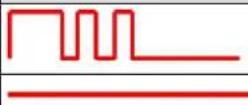 | Pairing Error Check the Tether connection | and Receiver is ON. | |
| Red | continuous | General hardware failure Replace transmitter | |||
| Orange | slow pulses Critical battery signal Replace batteries with charged | ones | |||
| Orange | double pulses | 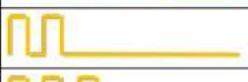 | Activated Order Release Order | ||
| Orange | 3 pulses | 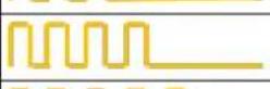 | Hall effect interference. Some mechanisms are disabled | Wait until interference disappears | |
| Orange | 4 pulses | Range Limiter warning. Out of Range Check | k Range Limier is ON with the correct ID. | ||
| Orange | 5 pulses |  | Wrong Selector Position Press Start to link | in this position, or return to the original position. | |
| Orange | 6 pulses Tilt Wa | normal | position | ||
| Orange | 7 pulses | Release Button + START Pressed The trans | mitter will switch off after release is done. | ||

Charger and battery
Transmitter Power supply
Ikore, IK1 have 2 different models depending on the power supply
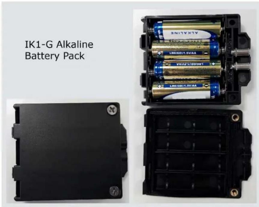
Transmitters with NO Suffix (Ikore, IK1-x1) use AA or AAA Alkaline Batteries
Transmitters with Suffix B (IkoreB, IK1-x2) use Li Ion Rechargeable Batteries BT11K
Alkaline Battery Recommendations
Transmitters that do use AA Battery Pack or AAA Batteries, it is highly recommended to use ALKALINE Batteries.
The use of Non Alkaline Batteries may diminish the Transmitter working hours.
Working hours that do appear on the Detailed description are always using Alkaline batteries.
Charger and battery
Charger and battery

Disposal note:
This symbol on the product indicates that it may not be disposed of as household waste. It must be handed over to the applicable take-back scheme for the recycling of electrical equipment.
- Dispose of the product through channels provided for this purpose.
- Comply with all local and currently applicable laws and regulations.
BC70K and BT11K specifications
BC70K battery charger
| Specification Value | |
| AC power supply 110 – 230 V, 50/60 Hz, ± 10%, | automatic switching |
| DC power supply, nominal 12 – 24 V |
BT11K battery
| Specification Value | |
| Voltage 3.7 V | |
| Capacity 1130 mAh Li-Ion | |
| Charging temperature 0°C to 45°C | |
| Discharge temperature -20°C to 60°C | |
| Charging mode Fast (<2.5 h) and intelligent | |
| Weight 23 g |
BC70K Battery Charger Set-up
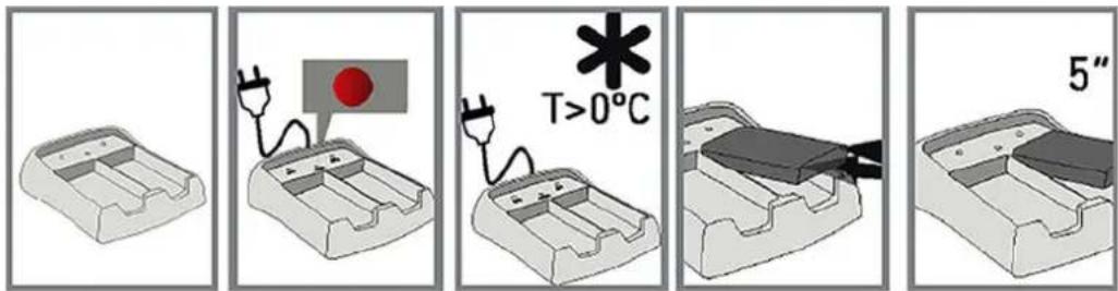
The battery charger has two charging compartments that can simultaneously charge two BT11K batteries. Use the information below to set up the BC70K battery charger.
-
Connect the charger to a power source using the provided power supply.
The red LED will switch on if the charger is properly connected. -
Place the batteries on the charger.
-
Optional: When charging two batteries, wait at least five seconds before inserting the second battery into the compartment.

Warning
Possible damage to battery.
The Battery Charger must be installed in a dry/interior environment. Make sure to charge batteries in environments with temperatures over 0^ C.
Charger and battery
BC70K Charger LEDs Status
The BC70K charger has a LED for each compartment (BAT 1 and BAT 2) and a common indicator (POWER).
| LED color / frequency Description | |
| Green LED / pulsing (BAT 1, BAT 2) The battery is being charged | |
| Green LED / continuous (BAT 1, BAT 2) The battery is completely charged | |
| Red LED / pulsing or continuous (BAT 1, BAT 2) The battery charger fault | |
| Red LED / continuous (POWER) The charger is properly connected to power source | |
Battery Charging Recommendations
The battery lifespan is estimated to 500 recharging cycles and is largely dependent on the conditions of use. To maximize the lifespan of the batteries and battery charger, follow these recommendations:
- Do not recharge the battery until it is completely flat, as shown with red LED slow pulse on the transmitter
• Always charge the batteries at temperatures between 0^ and 45^ C (the batteries will not become fully charged at temperatures exceeding 45^ C)
• Do not leave the battery charger or batteries in a direct sunlight
• Charge batteries at least once every three months
• Make the charge of at least 40% of the full charge. - Ideal Battery storage temperature should be between 15°C and 25°C.
- Avoid short circuits between the battery contacts; do not carry charged batteries in toolboxes or next to other metal objects (keys, coins, etc.)
• Always keep contacts clean - Caution! Risk of Explosion if Battery is Replaced by an incorrect type. Non Danfoss Battery use may void warranty
Charger and battery
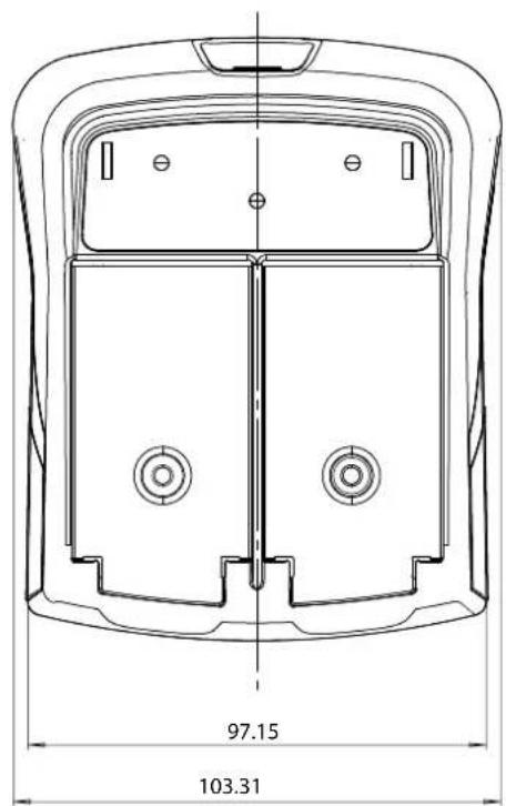
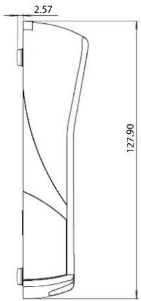
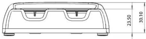
BC70K Battery Charger Dimensions
Dimensions (mm)
Products we offer:
- Cartridge valves
• DCV directional control valves
• Electric converters
Electric machines
Electric motors - Gear motors
- Gear pumps
• Hydraulic integrated circuits (HICs) - Hydrostatic motors
• Hydrostatic pumps - Orbital motors
- PLUS+1 ^® controllers
- PLUS+1 ^e displays
• PLUS+1* joysticks and pedals
• PLUS+1* operator interfaces - PLUS+1* sensors
- PLUS+1 ^ software
- PLUS+1 ^e software services, support and training
• Position controls and sensors
• PVG proportional valves
• Steering components and systems - Telematics
Danfoss Power Solutions is a global manufacturer and supplier of high-quality hydraulic and electric components. We specialize in providing state-of-the-art technology and solutions that excel in the harsh operating conditions of the mobile off-highway market as well as the marine sector. Building on our extensive applications expertise, we work closely with you to ensure exceptional performance for a broad range of applications. We help you and other customers around the world speed up system development, reduce costs and bring vehicles and vessels to market faster.
Danfoss Power Solutions – your strongest partner in mobile hydraulics and mobile electrification.
Go to www.danfoss.com for further product information.
We offer you expert worldwide support for ensuring the best possible solutions for outstanding performance. And with an extensive network of Global Service Partners, we also provide you with comprehensive global service for all of our components.
Local address:
Hydro-Gear
www.hydro-gear.com
Daikin-Sauer-Danfoss
www.daikin-sauer-danfoss.com
Danfoss
Power Solutions (US) Company 2800 East 13th Street
Ames, IA 50010, USA
D-24539 Neumünster, Germany
Phone: +49 4321 871 0
Danfoss
Power Solutions ApS Nordborgvej 81
DK-6430 Nordborg, Denmark
Phone: +45 7488 2222
Danfoss
Power Solutions Trading
(Shanghai) Co., Ltd.
Building #22, No. 1000 Jin Hai Rd Jin Qiao, Pudong New District
Shanghai, China 201206
Phone: +86 21 2080 6201
Danfoss can accept no responsibility for possible errors in catalogues, brochures and other printed material. Danfoss reserves the right to alter its products without notice. This also applies to products already on order provided that such alterations can be made without subsequent changes being necessary in specifications already agreed. All trademarks in this material are property of the respective companies. Danfoss and the Danfoss logotype are trademarks of Danfoss A/S. All rights reserved.
- Contents
- Safety instructions
- Technical description
- Maintenance
- Charger and battery
- FCC rules
- Warning
- IK1-G General Safety
- IK1 Safety Warnings
- Quick reference precautions
- IK1 Dimensions and Identification
- IK1 Transmitter Start up
- IK1 Detailed description
- IK1 Model code creation
- Pistol Grip Docking Station
- Default IK1 Layouts
- IK1-G maintenance tips
- Transmitter Power supply
- Alkaline Battery Recommendations
- Disposal note:
- BC70K and BT11K specifications
- BC70K Battery Charger Set-up
- BC70K Charger LEDs Status
- Battery Charging Recommendations
- BC70K Battery Charger Dimensions
- Products we offer:
- Go to www.danfoss.com for further product information.
- Hydro-Gear
- Daikin-Sauer-Danfoss
- Danfoss
Brand : DANFOSS
Model : IK1
Category : Remote control