
HDVF-C35W - Electronic viewfinder SONY - Free user manual and instructions
Find the device manual for free HDVF-C35W SONY in PDF.


| Product Type | HD Electronic Viewfinder |
| Brand | Sony |
| Model | HDVF-C35W |
| Display | 3.5-inch color TFT LCD |
| Resolution | 500 TV lines or more |
| Aspect Ratio | 16:9 |
| Image Display Area | 76.8 x 43.2 mm (H/V) |
| Brightness | 250 cd/m² (typical) |
| Power Supply | 10.5 to 17.0 V DC (supplied by camera) |
| Power Consumption | 6.3 W |
| Operating Temperature | -20°C to +45°C (-4°F to +113°F) |
| Storage Temperature | -20°C to +60°C (-4°F to +140°F) |
| Mass | 850 g (1 lb 14 oz) |
| Supported Formats | 1080/23.98PsF, 24PsF, 25PsF, 29.97PsF, 30PsF, 50i, 59.94i, 60i |
| Input Signals | Y: 1.0 Vp-p, synchronous, 75 Ω terminated; Pb, Pr: 0.7 Vp-p, asynchronous, 75 Ω terminated |
| Connector | Round type 20-pin CAMERA connector |
| Indicators | Green tally, TALLY/REC, BATT, MAG, spare, SAVE |
| Controls | PEAKING, CONTRAST, BRIGHT, ASSIGN 1/2, TALLY, ENTER, MENU, ZEBRA, ASPECT/DISPLAY |
| Menu Languages | English, Japanese (displayed on screen) |
| Supplied Accessories | Operation manual (1) |
| Optional Accessory | BKW-401 Viewfinder Rotation Assembly |
| Color Temperature | 6500K (with viewfinder barrel and eyepiece attached) |
| Cleaning | Use blower for dust; lens cleaner for lens; avoid solvents |
| Safety | Do not expose to rain or moisture; refer servicing to qualified personnel; avoid sunlight entering eyepiece |
Frequently Asked Questions - HDVF-C35W SONY
User questions about HDVF-C35W SONY
0 question about this device. Answer the ones you know or ask your own.
Ask a new question about this device
Download the instructions for your Electronic viewfinder in PDF format for free! Find your manual HDVF-C35W - SONY and take your electronic device back in hand. On this page are published all the documents necessary for the use of your device. HDVF-C35W by SONY.
USER MANUAL HDVF-C35W SONY
natural_image
Line drawing of a mechanical device with no visible text or symbolsnatural_image
Line drawing of a camera module with a lever and directional arrow indicating motion (no text or symbols)VF 筒部を取り付けるには
natural_image
Line drawing of a mechanical device with no visible text or symbolsnatural_image
Technical line drawing of a mechanical component with no visible text or symbols画像を拡大表示する
To reduce the risk of fire or electric shock, do not expose this apparatus to rain or moisture.
To avoid electrical shock, do not open the cabinet. Refer servicing to qualified personnel only.
AVERTISSEMENT
For the customers in the U.S.A.
This equipment has been tested and found to comply with the limits for a Class B digital device, pursuant to Part 15 of the FCC Rules. These limits are designed to provide reasonable protection against harmful interference in a residential installation. This equipment generates, uses, and can radiate radio frequency energy and, if not installed and used in accordance with the instructions, may cause harmful interference to radio communications. However, there is no guarantee that interference will not occur in a particular installation. If this equipment does cause harmful interference to radio or television reception, which can be determined by turning the equipment off and on, the user is encouraged to try to correct the interference by one or more of the following measures:
- Reorient or relocate the receiving antenna.
- Increase the separation between the equipment and receiver.
- Connect the equipment into an outlet on a circuit different from that to which the receiver is connected.
- Consult the dealer or an experienced radio/TV technician for help.
You are cautioned that any changes or modifications not expressly approved in this manual could void your authority to operate this equipment.
This product (fluorescent lamp in the liquid crystal display) contains mercury. Disposal of this product may be regulated if sold in the United States. For disposal or recycling information, please contact your local authorities or the Electronics Industries Alliance (http://www.eiae.org).
For the customers in Europe
This product with the CE marking complies with the EMC Directive issued by the Commission of the European Community.
Compliance with this directive implies conformity to the following European standards:
• EN55103-1 : Electromagnetic Interference (Emission)
- EN55103-2 : Electromagnetic Susceptibility (Immunity)
This product is intended for use in the following
Electromagnetic Environment(s):
E1 (residential), E2 (commercial and light industrial), E3 (urban outdoors), and E4 (controlled EMC environment, ex. TV studio).
For the customers in Europe
The manufacturer of this product is Sony Corporation, 1-7-1 Konan, Minato-ku, Tokyo, Japan.
The Authorized Representative for EMC and product safety is Sony Deutschland GmbH, Hedelfinger Strasse 61, 70327 Stuttgart, Germany. For any service or guarantee matters please refer to the addresses given in separate service or guarantee documents.
Location and Function of Parts .....25
Front Panel/Bottom Panel....26
Indicators on the LCD Screen.... 27
Attaching the Viewfinder to the Camera 28
Adjusting Focus and Screen....29
Adjusting the Focus ....29
Adjusting the Screen.... 30
Detaching the Eyepiece....31
Detaching the Viewfinder Barrel....32
Magnifying the Picture....33
Cleaning the Screen or Interior......34
Using the Menu 35
Basic Menu Operations....35
List of Menu Items.... 36
Specifications....39
Overview
The HDVF-C35W HD Electronic Viewfinder is a 3.5-inch color viewfinder for use with a Sony high-definition color camera.
This viewfinder has the following features:
Multiscan
In addition to the 60i format, formats such as 24PsF and 50i are supported through control signals from the camera.
Marker indication
When the camera setting allows the center marker or safety zone marker indication, the viewfinder can set the marker indication on or off.
High resolution and wide visual angle
The viewfinder features a high-resolution LCD, for a horizontal resolution of 500 TV lines or more.
The large LCD screen allows you to shoot with ease when the eyepiece is unattached.
Stable picture
The LCD screen provides a stable image without distortion, regardless of screen brightness.
High-performance loupe
The 2-group 4-element lens (including aspheric lens) delivers pictures with low distortion and allows adjustment over a wide range of visibility.
By attaching a commercially available 52-mm dia. close-up lens, dioptric range can be shifted towards longer sight.
Removable eyepiece
Detaching the eyepiece allows you to shoot while viewing the viewfinder screen from a distance.
Detachable viewfinder barrel and specially designed LCD screen mechanism
The viewfinder barrel can be detached with an easy operation. The LCD screen can then be turned towards the shooter for direct viewing of the LCD screen.
Picture magnification
Pictures can be magnified 2.25 times vertically and horizontally to facilitate focusing.
Grayscale display
A 10-step grayscale can be displayed at the left and right of the screen to provide a standard for fine iris adjustments.
Monochrome display
A color or monochrome display can be selected by a switch operation.
Switching to preset adjustment settings
Brightness, contrast, peaking, and chroma levels can be preset for selection through an assignable switch operation.
Assignable switches
Two assignable switches are provided for switching to preset adjustment settings and for assigning frequently used functions.
Notes
- The LCD panel fitted to this unit is manufactured with high precision technology, giving a functioning pixel ratio of at least 99.99%. Thus a very small proportion of pixels may be “stuck”, either always off (black), always on (red, green, or blue), or flashing. In addition, over a long period of use, because of the physical characteristics of the liquid crystal display, such “stuck” pixels may appear spontaneously.
These problems are not a malfunction. Note that any such problems have no effect on recorded data.
- When using the viewfinder at low temperatures, there will be a drop in dynamic resolution and brightness.
- Use a blower to remove dust from the screen.
- Do not use a solvent such as thinner to clean the screen.
Location and Function of Parts
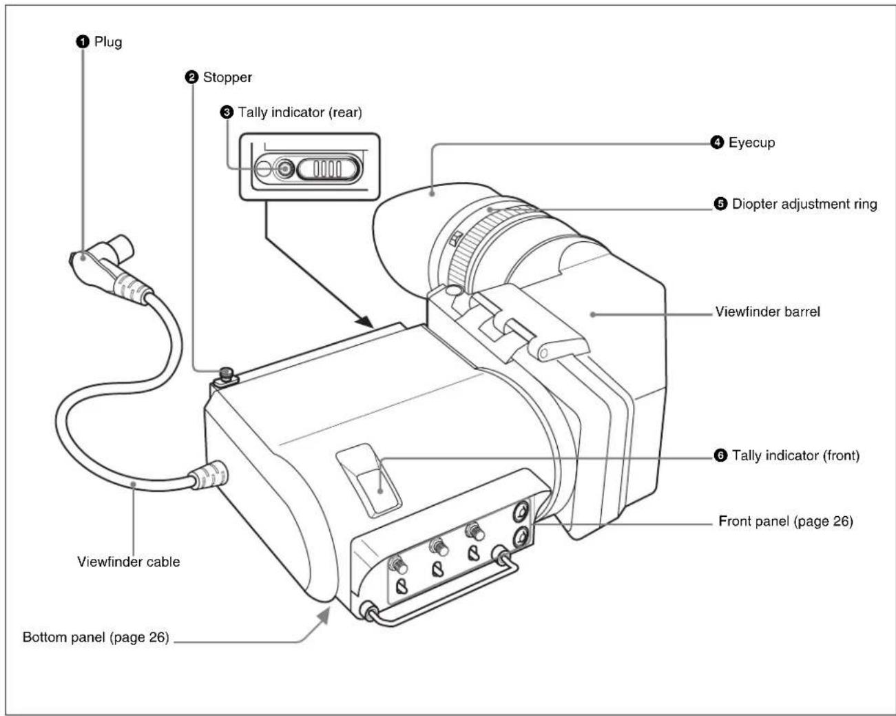
①Plug
Connect to the VF connector on the camera.
②Stopper
Prevents the viewfinder from coming off the camera when it is slid from side to side.
③Tally indicator (rear)
Lights up when the camera receives a tally control signal. This indicator can be covered when not in use.
④Eyecup
Blocks external light while you are shooting.
Over time the eyecup may become cracked. If this occurs, it should be exchanged.
Sony part number: 3-209-288-01
⑤ Diopter adjustment ring
Turn this until the image is sharpest for your eyesight.
⑥ Tally indicator (front)
Lights up when the camera receives a tally control signal. The brightness can be adjusted with the TALLY switch on the front panel (page 27). Set the TALLY switch to OFF when not in use.
Front Panel/Bottom Panel

①PEAKING control
Sharpens the edges in the picture. This control has no effect on the camera's video output signals. Turning the control clockwise increases the sharpness. This control is enabled only when "PRESET" in the PRESET menu (page 38) is set to "OFF."
②CONTRAST control
Adjusts the picture contrast. This control has no effect on the camera's video output signals. Turning the control clockwise increases the contrast. This control is enabled only when “PRESET” in the PRESET menu (page 38) is set to “OFF.”
③BRIGHT (brightness) control
Adjusts the picture brightness. This control has no effect on the camera's video output signals. Turning the control clockwise increases the brightness. This control is enabled only when “PRESET” in the PRESET menu (page 38) is set to “OFF.”
④ASSIGN (assignable) 1 switch
This switch works mainly in the following two ways: - Can be used to store preset adjustment settings or to assign frequently used function.
For details on assigning the function, see "FUNCTION menu" on page 36.
- In menu operations, this switch is used to move the mark upward or to increase the value.
This switch is factory-set to change the picture from color to monochrome.
⑤ASSIGN (assignable) 2 switch
This switch works mainly in the following two ways: - Can be used to store preset adjustment settings or to assign frequently used function.
For details on assigning the function, see "FUNCTION menu" on page 36.
- In menu operations, this switch is used to move the mark downward or to decrease the value.
This switch is factory-set to magnify the picture. Each push of this switch alternates normal and magnified display. In magnified display, the upper left, upper right, bottom left, bottom right, or center of the picture is magnified vertically and horizontally to 2.25 times the normal size. Keep the switch pushed down for about a second or longer to put the viewfinder into a selection mode where you can select the section to be magnified.
For details on magnification operations, “Magnifying the Picture” on page 33.
⑥TALLY switch
Controls the TALLY indicator (page 25) located on the front of the viewfinder.
HIGH: The tally indicator brightness is set to high.
OFF: The tally indicator is disabled.
LOW: The tally indicator brightness is set to low.
⑦ ENTER switch
Selects and enters menu items.
For details on the menu operations, see "Using the Menu" on page 35.
⑧MENU switch
Displays the menu.
For details on the menu operations, see "Using the Menu" on page 35.
⑨ ZEBRA (zebra pattern) switch
Controls the zebra pattern display on the viewfinder screen as follows:
ON: A zebra pattern appears and stays.
OFF: The zebra pattern disappears.
MOMENT: A zebra pattern appears and stays for about 5 seconds.
⑩ASPECT/DISPLAY switch
Turns the marker indication on and off, and switches between 4:3 and 16:9 aspect ratios for viewfinder screen display.
ASPECT: Each push of the switch to this position toggles the mask display on and off.
DISPLAY: When the marker indication is enabled with the camera, the marker indication on the viewfinder screen turns on and off every time you push the switch to this position.
Indicators on the LCD Screen
Indicators are located on the upper and lower parts of the LCD screen to indicate the status of the camera and the operating status of the magnification function.
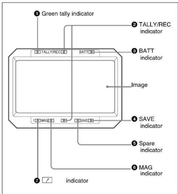
①Green tally indicator
Light up when the camera receives a green tally signal from a camera control unit.
②TALLY/REC (red tally/recording) indicator
Lights in red or flashes, to indicate the following.
Lit: Recording, or reception of a tally signal from a camera control unit.
Flashing: The VTR attached to the camera is not servo-locked.
③BATT (battery) indicator
Lights up or flashes, to indicate the status of the battery attached to the camera as follows.
Lit: The battery is drained.
Flashing: The voltage of the battery has dropped below the threshold value.
To prevent camera from shutting down, change the battery as soon as possible after this indicator begins flashing.
The threshold battery voltage value at which this indicator begins flashing can be set by the camera. For details, refer to the manual for the camera.
④SAVE (VTR power save) indicator
Light up when the VTR attached to the camera is in power-saving mode.
⑤Spare indicator
Available in near future.
⑥ MAG (magnification) indicator
Lights up when the image is magnified by using the
ASSIGN 2 switch (factory-setting) or the ASSIGN 1
switch with which the magnification function is assigned by menu operation (page 35).
⑦ (attention) indicator
This indicator lights when the camera detects certain conditions. The particular conditions which cause the indicator to light up can be set by the camera.
For information on how to set up and verify the conditions under which the indicator will light, refer to the manual for the camera being used.
Attaching the Viewfinder to the Camera
Note
When the viewfinder is attached, do not leave the camera (or the camcorder) with the eyepiece facing the sun. Direct sunlight can enter through the eyepiece, be focused in the viewfinder and cause fire.

1 Loosen the left-right positioning ring on the camera.
2 Insert the slide guide which is located on the front of the camera into the slide rail which is located on the back of the viewfinder.
3 Slide the viewfinder in the direction of the arrow.
4 Position the viewfinder by sliding it from side to side, and tighten the left-right positioning ring on the camera.
5 Connect the plug to the VF connector on the camera.
Note
Always check to be sure that the plug is firmly inserted into the camera's VF connector.
To detach the viewfinder
To detach the viewfinder from the camera, conduct the attachment procedure in reverse. When removing the viewfinder from the camera, pull up the stopper.
Note about loading in carrying case
When loading the camera with viewfinder attached into a carrying case, make sure that the camera and the viewfinder fit into the case without having to be forced. Applying undue pressure can result in damage to the camera or viewfinder.
Adjusting Focus and Screen
Adjusting the Focus
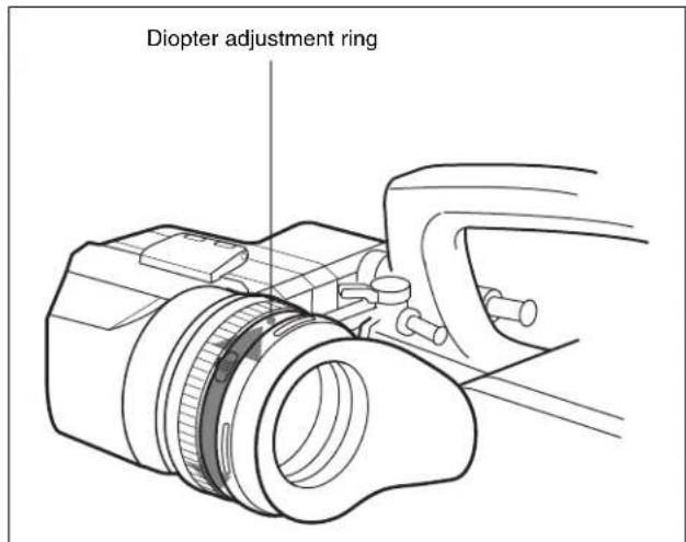
Turn the diopter adjustment ring until the image is sharpest for your eyesight.
To shift the dioptic range towards longer sight
Perform the procedure below to attach a commercially available close-up lens to the color conversion filter.
1 Remove the eyecup from the eyecup holder.
2 By following the procedure on "To disassemble the eyepiece for cleaning" on page 34, detach the color conversion filter from the eyecup holder.
3 Twist off the protection ring from the color conversion filter.
4 Screw the close-up lens into the groove on the color conversion filter (①), and screw the protection ring into the groove on the close-up lens (②).

flowchart
graph LR
    A["Color conversion filter"] --> B["Close-up lens"]
    B --> C["Protection ring"]
5 Replace the color conversion filter into the eyecup holder.

6 Replace the eyecup.
Adjusting the Screen
Note
Make sure that "PRESET" in the PRESET menu (page 38) is set to "OFF" before performing the procedure below. If it is set to "ON," the PEAKING, CONTRAST, and BRIGHT controls on the front panel do not operate and chroma level setting in the FUNCTION menu is not applied.
For details on the menu operation, see "Using the Menu" on page 35.
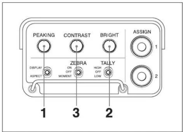
1 Turn the PEAKING control to adjust the peaking.
To make edges in the image sharper: Turn the control clockwise.
2 Turn the BRIGHT control to adjust the brightness of the screen.
To make the picture brighter: Turn the control clockwise.
3 Turn the CONTRAST control to adjust the screen contrast.
To increase the contrast: Turn the control clockwise.
4 Set "CHROMA" in the FUNCTION menu (page 36) to adjust the chroma level.
To prevent accidental operation of the controls
To prevent accidental operation of the PEAKING, CONTRAST, and BRIGHT controls, lock them by pushing down the MENU switch for 3 seconds or more so that "VR LOCK" appears in the viewfinder. To unlock the controls, push down the MENU switch for 3 seconds or more so that "VR UNLOCK" appears. The lock releases whenever the power is turned on.
To show the preset adjustment settings
Push the ENTER switch while the menu page is not displayed.
Preset values for “PRST BRIGHT,” “PRST CONTRAST,” and “PRST PEAKING” in the PRESET menu (page 38) appear at the lower part of the LCD screen for about three seconds.
The values to be displayed change depending on the settings of the PRESET menu.
| Menu item Setting Values displayed | ||
| PRESET OFF | Settings of | the PEAKING,CONTRAST, and BRIGHTcontrols on the front panel |
| PRESET SEL | 1^1) | Preset settings stored to“PRESET SEL 1” |
| PRESET SEL | 2^1) | Preset settings stored to“PRESET SEL 2” |
1) Appears only when "PRESET" is set to "ON."
Detaching the Eyepiece
Detaching the eyepiece gives you a clear view of the screen even with your eye away from the viewfinder. Also, detach the eyepiece to clean it.
For details on cleaning, see "Cleaning the Screen or Interior" on page 34.
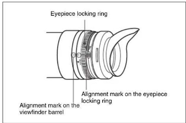
1 Turn the eyepiece locking ring fully counterclockwise to line up the red alignment mark on the eyepiece locking ring with the red alignment mark on the viewfinder barrel.
2 Detach the eyepiece.

Note
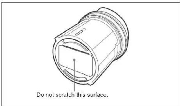
Take care not to scratch the eyepiece surface on the LCD side.
To refit the eyepiece
1 Align the alignment mark on the eyepiece locking ring with that on the viewfinder barrel.
2 Align the alignment mark on the end of eyepiece with that of the eyepiece locking ring, then insert the eyepiece into the viewfinder barrel until the eyepiece snaps into place.
3 Turn the eyepiece locking ring fully clockwise until the arrow of the "LOCK" indication points to the alignment mark on the viewfinder barrel.
Note
Do not use any other lenses except the supplied (built in) lens assembly. Other lenses may focus sunlight on the LCD, resulting in damage to the LCD.
Detaching the Viewfinder Barrel
By detaching the viewfinder barrel and turning the LCD screen towards the shooter, the LCD screen can be viewed directly. The barrel must be detached to clean the viewfinder's LCD screen and internal mirror.
For details on cleaning the LCD screen and internal mirror, see "Cleaning the Screen or Interior" on page 34.
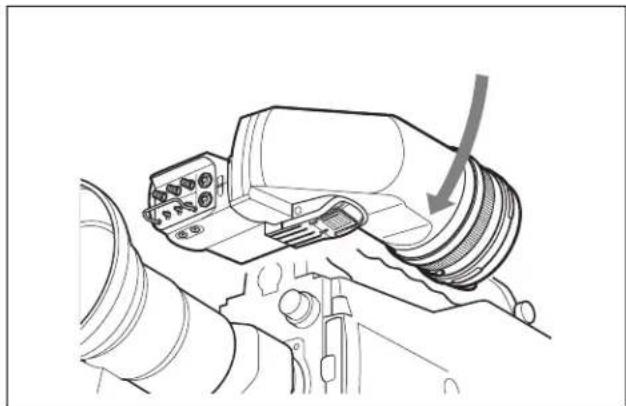
1 While pressing the release lever, pull up the viewfinder barrel.

2 Detach the pivots on the viewfinder barrel from two hooks on the upper part of the LCD screen.

natural_image
Line drawing of a mechanical device with no visible text or symbols3 If necessary, turn the LCD screen towards the shooter.

natural_image
Line drawing of a camera with control panel and directional arrow (no text or symbols)To reattach the viewfinder barrel
1 Attach the pivots on the viewfinder barrel to the two hooks on the upper part of the LCD screen.

natural_image
Line drawing of a mechanical device with no visible text or symbols2 Push down the viewfinder barrel until the release lever clicks into place.
Note
Before pushing down the viewfinder barrel, make sure that the pivots are securely engaged with the hooks on the LCD screen. Pushing down the viewfinder barrel forcibly may damage the unit.
natural_image
Technical line drawing of a mechanical component with no visible text or symbolsMagnifying the Picture
To facilitate focus adjustments, you can magnify the picture by 2.25 times vertically and horizontally. To magnify the picture, push the ASSIGN 1 switch (at its factory-setting) or the ASSIGN switch with which the magnifying function is assigned by the menu operation (page 35). Each push on the switch toggles between magnified and normal display.
To select the magnified section
The magnified section can be selected from among the upper left, upper right, lower right, lower left, and center (factory-setting) of the picture.

1 Keep the ASSIGN 1 or ASSIGN 2 switch pushed down for about a second or longer.
The MAG indicator at the lower part of the LCD screen lights up. At the same time, the LCD screen changes to magnified screen.
2 Keep the ASSIGN 1 or ASSIGN 2 switch pushed down, and release it when the screen shows the magnified picture of the desired section.
While the switch is pushed down, the magnified picture is maintained and the selection changes about once every second between upper left, upper right, lower right, lower left, and center, in that order. The actually magnified section changes at the same time. The magnified section selection can also be made with “POSITION” in the MAGNIFICATION menu (page 37).
To return to the normal display
Push the ASSIGN 1 or ASSIGN 2 switch. The MAG indicator at the lower part of the LCD screen turns off and the LCD screen returns to normal display. When “AUTO RELEASE” in the MAGNIFICATION menu (page 37) is set to “AUTO,” the LCD screen automatically returns to normal display after about five
seconds after the ASSIGN 1 or ASSIGN 2 switch is pushed.
Cleaning the Screen or Interior
To clean the screen or internal mirror of the viewfinder, detach the viewfinder from the camera, detach the viewfinder barrel from the body, and clean as explained below, taking care not to damage the components.
For information about detaching the viewfinder from the camera, see the procedure explained in “Attaching the Viewfinder to the Camera” on page 28.
For information about detaching the viewfinder barrel, see page 32.
To remove dust from the screen or the mirror
Use a dust blower.
To clean the lens or the protecting filter
Use a commercially available lens cleaner.
Notes
- Do not use organic solvents such as thinners.
- The LCD screen, mirror, and the filter are made of glass. Avoid physical shock.
- To protect the eyepiece from moisture and prevent the color conversion filter from coming off, be sure to always attach the eyecup.
- If the color conversion filter is not attached, the image becomes tinged with blue and the drip-proof capability may decrease.
To disassemble the eyepiece for cleaning
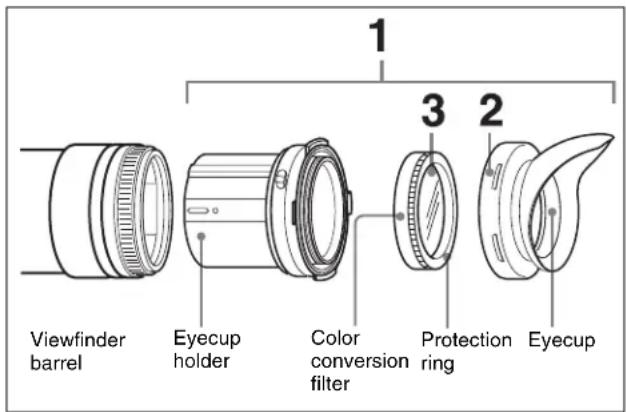
1 Detach the eyepiece from the viewfinder barrel.
For details on the detaching procedure, see page 31.
2 Remove the eyecup from the eyecup holder.
3 Remove the color conversion filter, together with the protection ring, from inside the eyecup holder.
Check the viewfinder after using it in harsh environments
Check the following points after using the viewfinder in a harsh environment such as a beach, a dusty area, or a hot spring resort.
- Use an airbrush to carefully remove any dust or sand from inside the viewfinder.
- Salt from seawater or sulphur from hot springs can result in whitish corrosion on the non-painted surfaces of the viewfinder. Use a cleaning solution such as ethanol to remove any adhering salt or sulphur from the non-painted surfaces as soon as possible.
- Clean the contacts of the connector.
- After cleaning the viewfinder, check that the viewfinder is working correctly.
Using the Menu
Many of the viewfinder's functions can be set by a menu operation.
Basic Menu Operations
1 Enter the menu.
Push the MENU switch.
A menu page appears in the viewfinder display.

The viewfinder menu can be displayed even while a picture from the camera is being displayed. The camera picture or menu darkens so that it appears dimly behind the menu.
2 Select a menu page.
①While the ? mark appears to the left of the page number (page select mode), push the ASSIGN 1 or ASSIGN 2 switch.
The menu changes to another page.
Page select mode

②When the desired menu page appears, push the ENTER switch.
The mark appears to the left of a menu item on the selected menu page (item select mode).
- To select another menu page, push the MENU switch to return to the page select mode.
- If the ● mark appears to the left of a menu item and the ? mark appears to the left of the setting (value
setting mode), push the MENU switch to return to item select mode. Push the MENU switch again to return to page select mode.
3 Select menu items.
① With the → mark is positioned to the left of a menu item on the selected menu page (item select mode), push the ASSIGN 1 or ASSIGN 2 switch to move the → mark to the desired menu item.
To move the mark upward, push the ASSIGN 1 switch. To move the mark downward, push the ASSIGN 2 switch.
Item select mode

② Position the → mark to the left of the desired menu item, and then push the ENTER switch.
The → mark to the left of the selected menu item changes to the ● mark, and the ● mark to the left of the setting changes to the ? mark. The menu is replaced by a screen that allows you to change the value of the setting (value setting mode).
Value setting mode
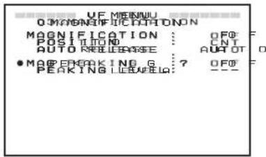
To select another menu item, push the MENU switch to return to item select mode.
4 Change the value of a setting.
With the ? mark positioned to the left of the setting (value setting mode), push the ENTER switch to change the value.
If the setting is a numerical value, push the ASSIGN 1 switch to increase the value, and push the ASSIGN 2 switch to decrease the value.
Keep pushing the switch to change the value rapidly.
5 Enter the setting.
Push the ENTER switch.
The setting is entered and the menu returns to item select mode.
If you push the ENTER switch before pushing the MENU switch, the setting returns to the value that was previously set and then the menu returns to item select mode.
6 Set other menu items.
Repeat steps 2 to 5 to set other menu items.
7 End menu operations.
Push the MENU switch repeatedly until the menu page disappears from the display.
To restore a setting to its initial value
Move the mark to the menu item to be restored, and then push the ASSIGN 1 and ASSIGN 2 switches at the same time while the ? mark is positioned to the left of the setting (value setting mode).
List of Menu Items
Notes
- Some settings cannot be selected unless the previous menu item is set to "ON."
- “--” appears to the left of settings that cannot be selected.
| No. | Page Menu item Settings | (default in □) | Description |
| 01 | FUNCTION ASSIGN. 1 | KNEE/PRST/MONO/MAG/GRAY | Assigns a function to the ASSIGN 1 switch.KNEE: Toggles the KNEE correction circuit ON or OFFPRST: Toggles PRESET between ON and OFF. When the switch is pushed down for 1 second or longer, preset adjustment settings stored to “PRESET SEL1” and “PRESET SEL 2” in the PRESET menu alternates.MONO: Toggles the display between color or monochromeMAG: Toggles the display between normal and magnified. When the switch is pushed down for 1 second or longer, the section of the screen to be magnified alternate.GRAY: Toggles grayscales ON or OFFFine adjustments can be made for each function on the various menu pages. |
| ASSIGN. 2 KNEE/PRST/MONO/MAG/GRAY | Assigns a function to the ASSIGN 2 switch. The assignable functions are the same as those for ASSIGN 1 switch. | ||
| KNEE | OFF/ONTurns the knee correction circuit ON or OFF. | ||
| MONOCROME | OFF/ONSelects the color picture (OFF) or monochrome picture (ON). | ||
| GRAY SCALE | OFF/ONShows (ON) or does not show (OFF) the grayscales at left and right edges of the picture. | ||
| CHROMA | -99 to 0 to 99Adjusts the chroma level. | ||
| 02 | TALLY DIM UP TALLY | HIGH | 1 to 50 to 100Adjusts the brightness of the tally indicator on the front of the viewfinder when the TALLY switch is set to “HIGH.” Adjust this item after setting the TALLY switch to “HIGH” and turning on the tally indicator. |
| UP TALLY LOW | 1 to 50 to 100Adjusts the brightness of the tally indicator on the front of the viewfinder when the TALLY switch is set to “LOW.” Adjust this item after setting the TALLY switch to “LOW” and turning on the tally indicator. |
| No. | Page Menu item Settings | (default in □) | Description | ||
| 03 | INDICATOR DIM IND | MODE | NOR/REV | Adjusts the brightness and sets the lighting positions of the indicators on the LCD screen.NOR: Adjusts the brightness of indicators when the viewfinder barrel is detached.REV: Adjusts the brightness of indicators when the viewfinder barrel is attached. | |
| G TALLY | 1 to 50 to 100 | Adjusts the brightness of the green tally indicator. Adjust this item after turning on the green tally indicator by external control. | |||
| R TALLY | 1 to 50 to 100 | Adjusts the brightness of the TALLY/REC indicator. Adjust this item after turning on the TALLY/REC indicator by external control. | |||
| BATTERY | 1 to 50 to 100 | Adjusts the brightness of the BATT indicator. | |||
| 04 | INDICATOR DIM2 IND | MODE | NOR/REV | Adjusts the brightness and sets the lighting positions of the indicators on the LCD screen.NOR: Adjusts the brightness of indicators when the viewfinder barrel is detached.REV: Adjusts the brightness of indicators when the viewfinder barrel is attached. | |
| NON STANDARD | 1 to 50 to 100 | Adjusts the brightness of the indicator. | |||
| MAG | 1 to 50 to 100 | Adjusts the brightness of the MAG indicator. | |||
| EXTEND | 1 to 50 to 100 | Adjusts the brightness of the spare indicator. | |||
| SAVE | 1 to 50 to 100 | Adjusts the brightness of the SAVE indicator. | |||
| 05 | MAGNIFICATION MAGNIFICATION | OFF/ON | Selects the normal display (OFF) or magnified display (ON). “OFF” (normal display) is selected whenever the power is turned on. | ||
| POSITION 1) | CNT/UP L/UP R/LOW R/ LOW L | Selects the section of the screen to be magnified.CNT: Magnifies the center of the screen by 2.25 timesUP L: Magnifies the upper left of the screen by 2.25 timesUP R: Magnifies the upper right of the screen by 2.25 timesLOW R: Magnifies the bottom right of the screen by 2.25 timesLOW L: Magnifies the bottom left of the screen by 2.25 times | |||
| AUTO RELEASE | AUTO/MAN | Specifies the manner in which the magnified display returns to the normal display.AUTO: After the magnified display appears by pushing the ASSIGN 1 or ASSIGN 2 switch, the display automatically returns to normal after a given amount of time.MAN: After the magnified display appears by pushing the ASSIGN 1 or ASSIGN 2 switch, the display returns to normal when the ASSIGN 1 or ASSIGN 2 switch is pushed again. | |||
| MAG PEAKING | OFF/ON | Specifies whether the peaking level menu setting is applied whenever the magnification function is used.OFF: The peaking level setting is not applied during magnified display and normal display.ON: The peaking level setting is applied during magnified display and normal display. | |||
| PEAKING LEVEL | 0 to 50 to 100 | Adjusts the peaking level that is applied during a magnified display when “MAG PEAKING” is set to “ON.” | |||
| 06 | RESET PRESET | OFF/ON | Selects the setting made by the PEAKING, CONTRAST, and BRIGHT controls on the front of the viewfinder and the chroma level setting in the FUNCTION menu or by “PRST BRIGHT,” “PRST CONTRAST,” “PRST PEAKING,” and “PRST CHROMA” in the PRESET menu.OFF: The setting of the PEAKING, CONTRAST, and BRIGHT controls on the front of the viewfinder is used.ON: The setting made in the PRESET menu is used. | ||
| PRESET SEL | 1/2 | Select the preset adjustment settings while “PRESET” is set to “ON.”1: Selects the settings stored to “PRESET SEL 1.”2: Selects the settings stored to “PRESET SEL 2.” | |||
| PRST BRIGHT | -99 to 0 to 99 | Adjusts the picture brightness while “PRESET” is set to “ON.” | |||
| PRST CONTRAST | -99 to 0 to 99 | Adjusts the picture contrast while “PRESET” is set to “ON.” | |||
| PRST PEAKING | 0 to 100 | Adjusts the peaking level while “PRESET” is set to “ON.”However, if the MAG PEAKING menu is set to “ON” during a magnified display, the setting of the PEAKING LEVEL menu is used. | |||
| PRST CHROMA | -99 to 0 to 99 | Adjusts the chroma level while “PRESET” is set to “ON.” | |||
| 07 | STATUS DISPLAY ASSIGN. 1 | OFF/ON | Specifies whether the status of the function stored to the ASSIGN 1 switch is displayed (ON) or not (OFF). | ||
| ASSIGN. 2 | OFF/ON | Specifies whether the status of the function stored to the ASSIGN 2 switch is displayed (ON) or not (OFF). | |||
| BRIGHT | OFF/ON | Specifies whether the status of the BRIGHT control on the front of the viewfinder is displayed (ON) or not (OFF). | |||
| CONTRAST | OFF/ON | Specifies whether the status of the CONTRAST control on the front of the viewfinder is displayed (ON) or not (OFF). | |||
| PEAKING | OFF/ON | Specifies whether the status of the PEAKING control on the front of the viewfinder is displayed (ON) or not (OFF). | |||
| 08 | DISPLAY MODE PANEL REV | AUTO/MAN | Specifies the manner in which the picture and characters in the LCD screen are flipped vertically.AUTO: The picture and characters automatically flip when the viewfinder barrel is detached.MAN: The picture flips according to the settings of the DISPLAY MODE menu. | ||
| PANEL REV | OFF/ON | Specifies whether the picture is flipped horizontally (ON) or not (OFF) while “PANEL REV” is set to “MAN.” | |||
| PANEL REV | OFF/ON | Specifies whether the picture is flipped vertically (ON) or not (OFF) while “PANEL REV” is set to “MAN.” | |||
| CHAR REV | OFF/ON | Specifies whether the characters are flipped horizontally (ON) or not (OFF) while “PANEL REV” is set to “MAN.” | |||
| V SHRINK | OFF/ON | Specifies whether the picture and characters are scaled down in vertical direction (ON) or not (OFF) for use with the anamorphic converter lens. | |||
1) If “ASSIGN. 1” or “ASSIGN. 2” in the FUNCTION menu is set to “MAG,” the magnified section changes as follows when the respective switch is held down during a magnified display.
CNT (☐) → UPL (☐) → UPR (☐) → LOW R (☐) → LOW L (☐)
Specifications
General
Power supply 10.5 to 17.0 V DC (supplied by the camera)
Power consumption
$$ 6. 3 \mathrm{W} $$
Operating temperature
$$ - 2 0 ^ {\circ} \mathrm{C} \text { to } + 4 5 ^ {\circ} \mathrm{C} (- 4 ^ {\circ} \mathrm{F} \text { to } + 1 1 3 ^ {\circ} \mathrm{F}) $$
Storage temperature
$$ - 2 0 ^ {\circ} \mathrm{C} \text { to } + 6 0 ^ {\circ} \mathrm{C} (- 4 ^ {\circ} \mathrm{F} \text { to } + 1 4 0 ^ {\circ} \mathrm{F}) $$
Mass
$$ 8 5 0 \mathrm{g} (1 \mathrm{lb} 1 4 \mathrm{oz}) $$
External dimensions

LCD
3.5-inch color TFT screen
Image display area dimensions
$$ 7 6. 8 \times 4 3. 2 \mathrm{mm} \left(3 ^ {1} / _ {8} \times 1 ^ {3} / _ {4} \text {inches}\right) (\mathrm{H} / \mathrm{V}, $$
$$ 1 6: 9 \text {aspect ratio)} $$
Performance
Brightness 250 cd/m ^2 (typical)
Resolution 500 or more lines
Supported formats
| Effective scanning lines | Format Horizontal scanning frequency (kHz) | Vertical scanning frequency (Hz) |
| 1080 23.98PsF | 26.97 47.95 | |
| 24PsF 27 48 | ||
| 25PsF 28.13 50 | ||
| 29.97PsF 33.72 59.94 | ||
| 30PsF 33.75 60 | ||
| 50i 28.13 50 | ||
| 59.94i | 33.72 59.94 | |
| 60i 33.75 60 |
Color temperature
6500K (with viewfinder barrel and eyepiece attached)
Indicators Green tally, TALLY/REC, BATT,
MAG, spare, SAVE
Input signals
Pb, Pr 0.7 Vp-p, asynchronous, 75 Ω terminated
Y 1.0 Vp-p, synchronous, 75 Ω terminated
Connector
CAMERA connector
Round type 20-pin
Supplied accessories
Operation manual (1)
Optional accessory
BKW-401 Viewfinder Rotation Assembly
Related accessories
HDC1500 Series HD Color Video Camera
HDW-F900R/750 ^1) /750P ^1) /730 ^1) HD Camcorder
1) To attach the viewfinder to the HDW-750/750P/730, the ROM (AT) version on the camcorder must be 1.50 or later.
Designs and specifications are subject to change without notice.
Note
Always verify that the unit is operating properly before use. SONY WILL NOT BE LIABLE FOR DAMAGES OF ANY KIND INCLUDING, BUT NOT LIMITED TO, COMPENSATION OR REIMBURSEMENT ON ACCOUNT OF THE LOSS OF PRESENT OR PROSPECTIVE PROFITS DUE TO FAILURE OF THIS UNIT, EITHER DURING THE WARRANTY PERIOD OR AFTER EXPIRATION OF THE WARRANTY, OR FOR ANY OTHER REASON WHATSOEVER.
The material contained in this manual consists of information that is the property of Sony Corporation and is intended solely for use by the purchasers of the equipment described in this manual.
Sony Corporation expressly prohibits the duplication of any portion of this manual or the use thereof for any purpose other than the operation or maintenance of the equipment described in this manual without the express written permission of Sony Corporation.
For Customer in China

- VF 筒部を取り付けるには
- 画像を拡大表示する
- AVERTISSEMENT
- For the customers in the U.S.A.
- For the customers in Europe
- Overview
- Multiscan
- Marker indication
- High resolution and wide visual angle
- Stable picture
- High-performance loupe
- Removable eyepiece
- Detachable viewfinder barrel and specially designed LCD screen mechanism
- Picture magnification
- Grayscale display
- Monochrome display
- Switching to preset adjustment settings
- Assignable switches
- Notes
- Location and Function of Parts
- ①Plug
- ②Stopper
- ③Tally indicator (rear)
- ④Eyecup
- ⑤ Diopter adjustment ring
- ⑥ Tally indicator (front)
- Front Panel/Bottom Panel
- ①PEAKING control
- ②CONTRAST control
- ③BRIGHT (brightness) control
- ④ASSIGN (assignable) 1 switch
- ⑤ASSIGN (assignable) 2 switch
- ⑥TALLY switch
- ⑦ ENTER switch
- ⑧MENU switch
- ⑨ ZEBRA (zebra pattern) switch
- ⑩ASPECT/DISPLAY switch
- Indicators on the LCD Screen
- ①Green tally indicator
- ②TALLY/REC (red tally/recording) indicator
- ③BATT (battery) indicator
- ④SAVE (VTR power save) indicator
- ⑤Spare indicator
- ⑥ MAG (magnification) indicator
- ⑦ (attention) indicator
- Attaching the Viewfinder to the Camera
- Note
- To detach the viewfinder
- Note about loading in carrying case
- Adjusting Focus and Screen
- Adjusting the Focus
- To shift the dioptic range towards longer sight
- Adjusting the Screen
- To prevent accidental operation of the controls
- To show the preset adjustment settings
- Detaching the Eyepiece
- To refit the eyepiece
- Detaching the Viewfinder Barrel
- To reattach the viewfinder barrel
- Magnifying the Picture
- To select the magnified section
- To return to the normal display
- Cleaning the Screen or Interior
- To remove dust from the screen or the mirror
- To clean the lens or the protecting filter
- Check the viewfinder after using it in harsh environments
- Using the Menu
- Basic Menu Operations
- Enter the menu.
- Select a menu page.
- Select menu items.
- Change the value of a setting.
- Enter the setting.
- Set other menu items.
- End menu operations.
- To restore a setting to its initial value
- List of Menu Items
- Specifications
- General
- LCD
- Performance
- Input signals
- Connector
- Supplied accessories
- Optional accessory
- Related accessories
- For Customer in China
Brand : SONY
Model : HDVF-C35W
Category : Electronic viewfinder