
HDVF-700A - Electronic viewfinder SONY - Free user manual and instructions
Find the device manual for free HDVF-700A SONY in PDF.


| Product Type | Electronic viewfinder |
| Model | HDVF-700A |
| Brand | Sony |
| Display Type | 7-type monochrome CRT, 90° deflection |
| Resolution | 800 lines (center), 600 lines (edges) |
| Brightness | 500 cd/m² |
| Picture Size | 120 × 90 mm (4:3 aspect ratio) |
| Power Supply | 10.5 to 17.0 V DC (supplied by camera) |
| Power Consumption | 33 W |
| Operating Temperature | -20°C to +45°C (-4°F to +113°F) |
| Mass | 5.0 kg (11 lb) not including hood |
| Dimensions (CRT) | 160 × 131 mm (6 3/8 × 5 1/4 in) |
| Connector | CAMERA connector (D-sub 25-pin) |
| Supported Formats | 1080/23.98PsF, 1080/24PsF, 1080/25PsF, 1080/29.97PsF, 1080/30PsF, 1080/50i, 1080/59.94i, 1080/60i, 1035/59.94i, 1035/60i |
| Peaking Adjustment | Continuously variable 0 to 18 dB (17 MHz) |
| Tilt Range | 60° upwards, 50° downwards |
| Height Positions | 3 positions (standard/low, middle, top) |
| Tally Lamps | Red and green, plus external tally lamp with dimmer |
| Drip-Proof | Yes (light rain resistant) |
| Hoods | Studio monitor hood (supplied), OB hood (optional VFH-770) |
| Accessories Supplied | Studio monitor hood, number plate, fuse, operation manual |
| Safety | Do not open cabinet; refer servicing to qualified personnel; FCC Class A, CE compliant |
Frequently Asked Questions - HDVF-700A SONY
User questions about HDVF-700A SONY
0 question about this device. Answer the ones you know or ask your own.
Ask a new question about this device
Download the instructions for your Electronic viewfinder in PDF format for free! Find your manual HDVF-700A - SONY and take your electronic device back in hand. On this page are published all the documents necessary for the use of your device. HDVF-700A by SONY.
USER MANUAL HDVF-700A SONY
OPERATION MANUAL 1st Edition (Revised 2)
Japanese/English
目次
警告 2(J)
注意....2(J)
概要 3(J)
各部の名称と働き 4(J)
カメラに取り付ける……6(J)
natural_image
Line drawing of hands operating a camera with directional arrows indicating motion (no text or symbols)natural_image
Line drawing of a camera module with an open lid and directional arrow indicating rotation (no text or symbols)OB用屋外フード(別売り)

Dangerously high voltages are present inside the set. Do not open the cabinet. Refer servicing to qualified personnel only.
For the customers in the USA
This equipment has been tested and found to comply with the limits for a Class A digital device, pursuant to Part 15 of the FCC Rules. These limits are designed to provide reasonable protection against harmful interference when the equipment is operated in a commercial environment. This equipment generates, uses, and can radiate radio frequency energy and, if not installed and used in accordance with the instruction manual, may cause harmful interference to radio communications. Operation of this equipment in a residential area is likely to cause harmful interference in which case the user will be required to correct the interference at his own expense.
You are cautioned that any changes or modifications not expressly approved in this manual could void your authority to operate this equipment.
The shielded interface cable recommended in this manual must be used with this equipment in order to comply with the limits for a digital device pursuant to Subpart B of Part 15 of FCC Rules.
For the customers in Europe
This product with the CE marking complies with the EMC Directive (89/336/EEC) issued by the Commission of the European Community.
Compliance with this directive implies conformity to the following European standards:
• EN55103-1: Electromagnetic Interference (Emission)
• EN55103-2: Electromagnetic Susceptibility (Immunity)
This product is intended for use in the following Electromagnetic Environment(s):
E1 (residential), E2 (commercial and light industrial), E3 (urban outdoors) and E4 (controlled EMC environment, ex. TV studio).
Location and Function of Parts 3(E)
Attaching to the Camera 6(E)
Adjusting the Position — Tilting.... 8(E)
Adjusting the Screen 9(E)
Attaching Accessories 10(E)
Specifications.... 12(E)
Overview
The HDVF-700A HD Electronic Viewfinder is a 7-type monochrome viewfinder for use with a Sony high-definition color camera.
This viewfinder has the following features:
Multiscan
In addition to the 60i format, formats such as 24PsF and 50i are supported for control signals from the camera.
16:9 display capability
When operated from an external device such as a camera control unit, the screen can be switched between 16:9 and 4:3 display modes.
High resolution
The viewfinder uses a high-resolution cathode-ray tube, providing 800 or more lines of horizontal resolution.
Stable picture
A high-voltage regulation circuit provides a stable image with a minimum of distortion, regardless of screen brightness.
Continuously variable peaking
A continuously variable peaking circuit provides a sharp image, making it easy to focus the camera.
Tally lamps
The viewfinder has red and green tally lamps which light in response to tally signals.
Superior usability
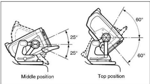
The viewfinder height may be set to one of three positions, and it may be tilted up to 60^ upwards or 50^ downwards.
Drip-proof construction
The drip-proof design is able to withstand light rain, making the viewfinder well suited to outdoor use.
Studio monitor hood, outdoor hood
The viewfinder may be fitted with a strong, easy-to-use studio hood (supplied), or an outdoor broadcasting (OB) hood with excellent shading ability (option).
Energy-saving design
The viewfinder will accept a wide range of power supply voltage (from 10.5 to 17 volts) with low power consumption (33 watts).
Location and Function of Parts


① PEAKING control ^1)
When the PEAKING switch ② is set to ON, this control can be used to sharpen the edges in the picture. Turning the control clockwise will increase the sharpness. The peaking can be adjusted from 0 to 18 dB.
② PEAKING switch
When this switch is set to ON, peaking can be adjusted using the PEAKING control ①. When the switch is set to OFF, the PEAKING control ① is disabled, and the peaking value will be 0 dB.
③ Friction adjustment knob
Used to adjust the amount of friction in the tilting mechanism.
4 Lift-lock release knob
The viewfinder height can be adjusted while pulling this knob. By releasing the knob after adjusting the height to the standard (low), middle position, or top position, the viewfinder will remain fixed at that height.
⑤ POWER switch
Turns the power supply from the camera to the viewfinder on and off.
6 ⚠ (attention) indicator
This indicator lights when the camera detects certain conditions. The particular conditions which cause the indicator to light up are set by the camera.
For information on how to set up and verify the conditions under which the indicator will light, refer to the manual for the camera being used.
⑦ Green tally lamps ^2)
Light up when the camera receives a green tally signal.
⑧ BRIGHT (brightness) control ^1)
Used to adjust the picture brightness.
9 Lock lever
This lever is used to lock the viewfinder into a desired angle. The angle is locked when the lever is pushed towards the camera lens. When the lever is pulled toward the back of the camera, the angle can be adjusted. The tilt mechanism will resist movement with the amount of friction set by the friction adjustment knob ③.
10 CONTRAST control ^1)
Used to adjust the picture contrast.
⑪ TALLY ON/OFF switch
Controls the external tally lamp 14. When set to ON, the external tally lamp will operate. When set to OFF, the lamp will not operate (will not light in response to a tally signal).
⑫ BATT (battery) indicator
This indicator blinks when the voltage output of the camera battery drops. When the battery reaches a point that it may no longer be used, the indicator will light up.
To prevent camera shutdown due to the battery running down, change the battery as soon as possible after this indicator begins blinking.
The threshold battery voltage value to make this indicator begin blinking is set by the camera. For details, refer to the manual for the camera.
13 Red tally lamps ^2)
Light up when the camera receives a red tally signal.
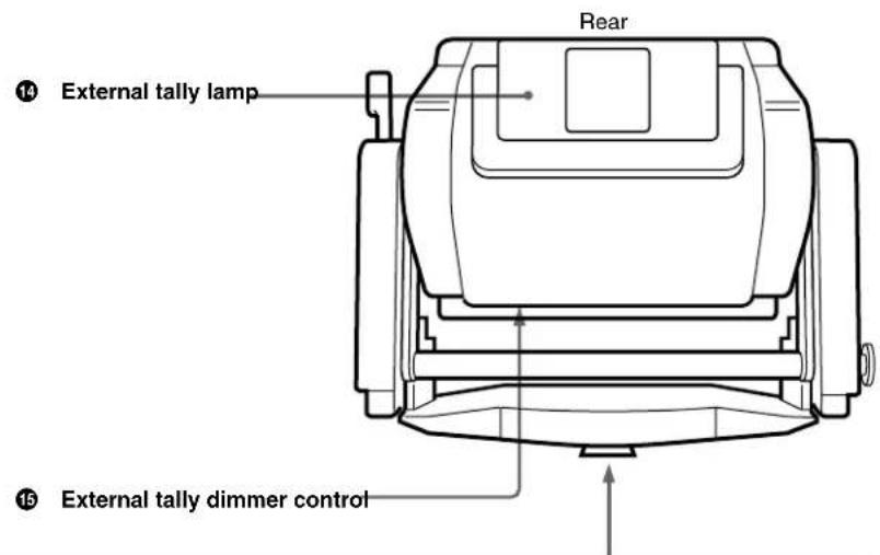
14 External tally lamp
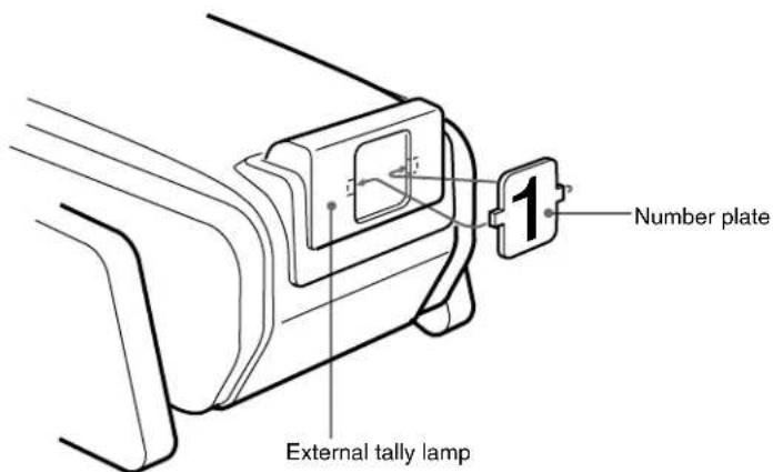
Lights up red in response to a red tally signal. Can be used to display the camera number by attaching one of the supplied number plates (0 through 9).
15 External tally dimmer control
Used to adjust the brightness of the external tally lamp. Use a screwdriver to turn the control clockwise to increase the brightness, or counterclockwise to dim the lamp.
16 CAMERA connector (D-sub 25-pin)
Used to connect to the camera's viewfinder connector.
⑰ Mounting wedge
To attach the viewfinder to a camera, the mounting wedge is inserted into the V-shaped groove on the top of the camera.
Attaching to the Camera
The viewfinder is attached to the panning base mounting plate (see the figure below) on the top of the camera.
Note
- When attaching the viewfinder to or removing it from a camera, always be sure to lock the viewfinder in standard position (the lowest position).
- Before attaching the viewfinder to the camera, check to be sure that the VF connector on the camera's panning base mounting plate faces in the direction 90^ clockwise to the camera's control panel.
For more information on adjusting the viewfinder position, see the section "Adjusting the Position - Tilting" on page 8(E).

Viewfinder attachment mechanism
1 Aligning the mounting wedge with the V-shaped groove, and the protrusions on the viewfinder with the depressions on the left and right of the panning base mounting plate, set the viewfinder on the panning base mounting plate.

2 Holding on to the handle, push the viewfinder forwards.
The CAMERA connector will mate with the camera's VF connector.

Removing the viewfinder
Note
Before detaching the viewfinder from the camera, release the camera's panning lock lever and turn the viewfinder in the direction 90^ clockwise to the camera's control panel. You cannot detach the viewfinder from the camera unless it is in this position.
While pushing in the lock release tabs, grasp the viewfinder handle and lift the viewfinder to remove it from the camera.

Adjusting the Position — Tilting
Note
When moving the camera with the viewfinder attached, always lower the viewfinder to its standard (lowest) position and push the lock lever towards the camera lens. Also, verify that the lift-lock release knob is fitted into the standard position depression.
1 Pull the lock lever towards the rear of the camera.

2 While pulling the lift-lock release knob, grasp the viewfinder handle and lift the viewfinder to its middle or top position.
Note
If the viewfinder is raised while holding onto the lift-lock release knob only, the viewfinder may not lock properly in the desired height position. Always lift the viewfinder while holding onto both the lift-lock release knob and the handle.

natural_image
Line drawing of a handheld electronic device with hands operating it, showing mechanical components and directional arrows (no text or symbols)3 Turn the friction adjustment knob to set the desired tilt friction.

4 Adjust the tilt angle.
After setting the viewfinder to the desired angle, push the lock lever towards the camera lens to lock the viewfinder in position.
Adjusting the Screen

1 Turn the BRIGHT control to adjust the brightness of the screen. Turning the control clockwise makes the picture brighter.
Note
When the BRIGHT control is turned counterclockwise as far as it will go, no picture may be displayed on the screen.
2 Turn the CONTRAST control to adjust the screen contrast.
3 Set the PEAKING switch to ON.
4 Turn the PEAKING control to adjust the peaking. Turn the control clockwise to make edges in the image sharper.
Attaching Accessories
Attaching hoods
This section describes how to attach the supplied studio monitor hood. The VFH-770 Outdoor Hood (sold separately) is attached in the same manner.
1 Hook the hood on the projection over the screen.

2 Tighten the screw to fix the hood in place.

The hood direction can be adjusted up by 30^ .
Studio monitor hood

natural_image
Line drawing of a camera module with an open lid and directional arrow indicating rotation (no text or symbols)Outdoor (OB) hood (sold separately)

When the outdoor hood is difficult to move, or when it won't stay in a set position, adjust the tilt friction using the screw. Turning the screw clockwise will tighten the joint, and turning it counterclockwise will loosen it.
Attaching a number plate
Insert the tabs on the sides of the required number plate (supplied) into the slots on the sides of the external tally lamp.
General
Power supply 10.5 to 17.0 V DC (supplied by the camera)
Power consumption
33 W
Operating temperature
-20^ to +45^ (-4^ to +113^)
Mass 5.0 kg (11 lb) not including hood
External dimensions:

CRT
7-type monochrome, 90° deflection
Dimensions 160× 131mm (6 ^3 / 8× 5^1 / 4 in)
Picture size 120 × 90 ~mm (4 ^3/4 × 3^5/8 in)
(4:3 aspect ratio)
Deflection and high voltage
Brightness 500 cd/m ^2
Resolution 800 lines at center
600 lines at edges
Geometric distortion
2.0% or less
EHT voltage regulation
within ±2.0%
EHT voltage 12.5 kV (standard)
Input voltages and signal characteristics
Supported formats
Effective scanning lines / Format / Horizontal
scanning frequency / Vertical scanning frequency
1080/23.98PsF/26.97kHz/47.95Hz
1080 / 24PsF / 27kHz / 48Hz
1080 / 25PsF / 28.13kHz / 50Hz
1080/29.97PsF/33.72kHz/59.94Hz
1080 / 30PsF / 33.75kHz / 60Hz
1080 / 50i / 28.13kHz / 50Hz
1080/59.94i/33.72kHz/59.94Hz
1080 / 60i / 33.75kHz / 60Hz
1035 / 59.94i / 33.72kHz / 59.94Hz
1035 / 60i / 33.75kHz / 60Hz
Video input 1.0 Vp-p±6 dB, 75-Ω terminated
Video input 1.0 Vp-p ±6 dB (SMPTE 240M), 75-Ω terminated
DC restoration Back porch type
Back porch level: within 2% of peak
(The fluctuation in black level against 10% to 90% fluctuation in APL)
Frequency response
0.1 to 23 MHz (±2 dB)
23 to 27 MHz (±3 dB)
Peaking 0 to 18 dB (17 MHz)
Synchronization Line pull range:
Horizontal, ±500 Hz or more
Vertical, -10 Hz or more
Line hold range:
±500 Hz or more
Connectors
CAMERA connector
D-sub 25-pin
Supplied accessories
Studio monitor hood (1)
Number plate (1)
Fuse (1)
Operation manual (1)
Optional accessories
VFH-770 Outdoor Hood
Related products
HDC-900/950 HD Color Video Camera
CA-905L Large Lens Adaptor
BKP-9057 Viewfinder Saddle
Design and specifications are subject to change without notice.
The material contained in this manual consists of information that is the property of Sony Corporation and is intended solely for use by the purchasers of the equipment described in this manual.
Sony Corporation expressly prohibits the duplication of any portion of this manual or the use thereof for any purpose other than the operation or maintenance of the equipment described in this manual without the express written permission of Sony Corporation.
For Customer in China
Printed on recycled paper.
Printed in Japan
2007.11.13
© 2000

- 目次
- Dangerously high voltages are present inside the set. Do not open the cabinet. Refer servicing to qualified personnel only.
- For the customers in the USA
- For the customers in Europe
- Overview
- Multiscan
- 16:9 display capability
- High resolution
- Stable picture
- Continuously variable peaking
- Tally lamps
- Superior usability
- Drip-proof construction
- Studio monitor hood, outdoor hood
- Energy-saving design
- Location and Function of Parts
- ① PEAKING control 1)
- ② PEAKING switch
- ③ Friction adjustment knob
- Lift-lock release knob
- ⑤ POWER switch
- ⚠ (attention) indicator
- ⑦ Green tally lamps 2)
- ⑧ BRIGHT (brightness) control 1)
- Lock lever
- CONTRAST control 1)
- ⑪ TALLY ON/OFF switch
- ⑫ BATT (battery) indicator
- Red tally lamps 2)
- External tally lamp
- External tally dimmer control
- CAMERA connector (D-sub 25-pin)
- ⑰ Mounting wedge
- Attaching to the Camera
- Note
- Removing the viewfinder
- Adjusting the Position — Tilting
- Adjusting the Screen
- Attaching Accessories
- Attaching hoods
- Studio monitor hood
- Outdoor (OB) hood (sold separately)
- Attaching a number plate
- General
- CRT
- Deflection and high voltage
- Input voltages and signal characteristics
- Connectors
- Supplied accessories
- Optional accessories
- Related products
Brand : SONY
Model : HDVF-700A
Category : Electronic viewfinder