
ProHD BR-DE900 - Uncategorized JVC - Free user manual and instructions
Find the device manual for free ProHD BR-DE900 JVC in PDF.


| Product Type | Professional Blu-ray Disc Recorder/Player |
| Brand | JVC |
| Model | ProHD BR-DE900 |
| Recording Media | BD-R/RE, DVD-R/RW, DVD+R/RW |
| Video Recording Format | MPEG-2, H.264, ProHD (1920x1080, 1280x720) |
| Audio Recording Format | Linear PCM, Dolby Digital, AAC |
| Video Inputs | HD-SDI (x2), HDMI, Composite, Component |
| Video Outputs | HD-SDI (x2), HDMI, Composite, Component |
| Audio Inputs/Outputs | XLR (2 ch), RCA, Digital Optical |
| Dimensions (W x H x D) | 430 x 88 x 350 mm |
| Weight | Approx. 6.5 kg |
| Power Supply | AC 110-240V, 50/60Hz |
| Power Consumption | Approx. 45 W |
| Recording Modes | HQ, SP, LP |
| Playback Compatibility | BD, DVD, CD |
| Network Connectivity | Ethernet (100Base-TX) |
| Control Interface | RS-232C, Remote (LAN) |
| Front Panel Display | LCD with time code and status |
| Maintenance | Clean exterior with soft dry cloth; avoid dust and moisture |
| Safety | Use supplied power cord; do not expose to rain or moisture |
| Repairability | Contact authorized JVC service center for repairs |
Frequently Asked Questions - ProHD BR-DE900 JVC
User questions about ProHD BR-DE900 JVC
0 question about this device. Answer the ones you know or ask your own.
Ask a new question about this device
Download the instructions for your Uncategorized in PDF format for free! Find your manual ProHD BR-DE900 - JVC and take your electronic device back in hand. On this page are published all the documents necessary for the use of your device. ProHD BR-DE900 by JVC.
USER MANUAL ProHD BR-DE900 JVC
ProHD BR-DE900
HEVC and H.264 Decoding Appliance
User Manual
Version 1.1
Contents
Safety Instructions....iii
Declaration of Conformity and Regulatory Compliance......iv
Copyright Notice......vi
Open Source Documentation ......vii
Chapter 1 About This Manual ....8
General 8
Manual Structure and Use....8
Chapter 2 ProHD BR-DE900 Overview....9
The Product....9
System Requirements .... 10
I/O Specifications....11
ProHD BR-DE900 Front Panel....11
ProHD BR-DE900 Rear Panel....13
Chapter 3 Getting Started ....14
Initial Connection and Setup....14
Retrieving or Setting Network Parameters through a USB Thumb Drive ....17
Chapter 4 Setup and Operations....19
Using the ProHD BR-DE900 Interface 19
The Main Menu....20
Dashboard Frame 20
The Dashboard Page ......21
The Channel Page....25
Input Channel Configuration....28
The Decoder Settings Page....33
The System Page ...... 36
The Configurations Page....40
The General Page......42
Chapter 5 Firmware Upgrade....44
Upgrading the Firmware....44
Chapter 6 Technical Specifications....46
Compliance....46
Environmental 46
Physical 46
Functional Description 47
Appendix A Warranty 49
Index 51
Safety Instructions
- Use the following safety guidelines to help protect your ProHD BR-DE900 unit from potential damage and to ensure your own personal safety.
- Make sure that only authorized personnel installs, connects and maintains ProHD BR-DE900 and its components.
- Read and follow all instructions marked on the product and in the documentation before you operate your system. Retain all safety and operating instructions for future use.
- As a power switch is not incorporated in the equipment, the power plug must be disconnected to shut down the unit
When using ProHD BR-DE900
• Install the system on a secured and stable surface.
- To help prevent electric shock, plug the power cable into properly grounded sources. Use only properly grounded extensions and adapters as the need arises.
- Make sure that nothing rests on your ProHD BR-DE900 power cable and that the cables are not located where they can be stepped or tripped over.
- Do not spill food or liquids on your unit.
- Keep your ProHD BR-DE900 unit away from radiators and heat sources. Do not place your ProHD BR-DE900 unit on a bed, sofa, or rug.
- When you disconnect a power cable, pull on its connector or on its strain relief loop not on the cable itself.
• ESD Warning: Normal handling precautions should be taken to avoid static discharge.

WARNING:
Do not try to open or replace parts as this will void your warranty.
Declaration of Conformity and Regulatory Compliance
USA: FCC Part 15 Class A

This equipment has been tested and found to comply with the limits for a Class A digital device, pursuant to part 15 of the FCC Rules. These limits are designed to provide reasonable protection against harmful interference when the equipment is operated in a commercial environment. This equipment generates, uses, and can radiate radio frequency energy and, if not installed and used in accordance with the instruction manual, may cause harmful interference to radio communications. Operation of this equipment in a residential area is likely to cause harmful interference in which case the user will be required to correct the interference at his own expense.
Operation is subject to the following two conditions: (1) This device may not cause harmful interference, and (2) this device must accept any interference received, including interference that may cause undesired operation.

WARNING:
Modifying the equipment without JVC authorization may result in the equipment no longer complying with FCC requirements for Class A digital devices. In that event, your right to use the equipment may be limited by FCC regulations, and you may be required to correct any interference to radio or television communications at your own expense.
Canada: ICES-003
This Class A digital apparatus complies with Canadian ICES-003.
This product fulfills the essential requirements of the below European directives and thus bears the CE marking.
2004/108/EC Electromagnetic Compatibility (EMC)
2014/35/EU Low voltage (LVD)
2011/65/EU Restriction of the use of certain hazardous substances in electrical and electronic equipment (RoHS recast)
The following relevant harmonized standards were used during the assessment process:
EN 60950-1 Information technology equipment - Safety -- Part 1: General requirements
EN 61000-3-2 Limits for harmonic current emissions
EN 61000-3-3 Limitation of voltage changes, voltage fluctuations and flicker in public low-voltage supply systems
EN 55022 Information technology equipment - Radio disturbance characteristics - Limits and methods of measurement
EN 55024 Information technology equipment - Immunity characteristics - Limits and methods of measurement
Per directive 2012/19/EU (Waste of Electrical and Electronic Equipment - WEEE), this product

must not be disposed of as unsorted waste and must be collected separately.
Copyright Notice
JVC, AND ITS AFFILIATES ("COMPANY") FURNISH THIS DOCUMENT "AS IS," WITHOUT WARRANTY OF ANY KIND. THE COMPANY DISCLAIMS ALL WARRANTIES, EXPRESS OR IMPLIED, INCLUDING, WITHOUT LIMITATION, THE IMPLIED WARRANTIES OF MERCHANTABILITY, FITNESS FOR A PARTICULAR PURPOSE, NON-INFRINGEMENT AND THOSE ARISING FROM A COURSE OF PERFORMANCE, A COURSE OF DEALING, OR TRADE USAGE. THE COMPANY SHALL NOT BE LIABLE FOR ANY ERROR, OMISSION, DEFECT, DEFICIENCY OR NONCONFORMITY IN THIS DOCUMENT AND DISCLAIMS ALL LIABILITY, INCLUDING LIABILITY FOR INFRINGEMENT OF ANY INTELLECTUAL PROPERTY RIGHTS RELATED TO THE INFORMATION CONTAINED IN THIS DOCUMENT.
No license, expressed or implied, to any intellectual property rights is granted under this document. This document, as well as the software described in it, are furnished under a separate license and shall only be used or copied in accordance with the terms of the applicable license. The information in this document is furnished for informational use only, is subject to change without notice, and should not be construed as any commitment by the company. Except as permitted by the applicable license, no part of this document may be reproduced, stored in a retrieval system, or transmitted in any form or by any means without the express written consent of the company.
Names and logos identifying products of JVC in this document are registered trademarks or trademarks of JVC respectively. All other trademarks mentioned in this document are the property of their respective owners.
Copyright © 2018 JVC. All rights reserved.
http://www.jvc.com/
Open Source Documentation
The software included in this product contains open source software components licensed under open source licenses (such as GPL - General Public License).
For information about copyright holders and licenses, or to receive a copy of the corresponding source code to which you may be entitled under the applicable open source license, please contact JVC.
About This Manual
In This Chapter
General....8
Manual Structure and Use 8
General
Information in this document is subject to change without notice. JVC assumes no responsibility for any errors that may appear in this manual. Companies, names and data used in examples herein are fictitious unless otherwise noted. No part of this document may be copied or reproduced in any form, or by any means, electronic or mechanical, for any purpose, without the express written permission of JVC. JVC provides no warranties with respect to this documentation and disclaims any implied warranties of merchantability or fitness for a particular purpose.
Manual Structure and Use
This manual is structured in a modular format, containing the following sections:
• ProHD BR-DE900 Overview (on page 9)
Describes the ProHD BR-DE900 product, its system requirements and I/O specifications.
• Getting Started (on page 14)
Describes how to connect to the appliance for the first time.
- Setup and Operations (on page 19)
Describes how to set and configure ProHD BR-DE900 appliance, obtain an event log and load new licenses.
- Firmware Upgrade (on page 44)
Describes how to upgrade ProHD BR-DE900 firmware.
• Technical Specifications (on page 46)
• Describes the technical specifications of the ProHD BR-DE900 appliance.
ProHD BR-DE900 Overview
In This Chapter
The Product....9
System Requirements.... 10
I/O Specifications.... 10
The Product
ProHD BR-DE900 is an advanced industrial-grade, HEVC (H.265) and H.264 (AVC) decoding appliance. ProHD BR-DE900 is the preferred Hardware decoder for JVC Professional streaming cameras. The ProHD BR-DE900 is designed for low latency decoding of high-definition and standard-definition video sources across the enterprise, utilizing minimal bandwidth while preserving broadcast-quality video up to full HD 1080p60 resolution.
The decoding and streaming appliance supports a wide range of streaming protocols including UDP TS, RTP TS, SRT, ProMPEG, Zixi™ streaming with Error Correction mechanism for ensuring secure, error-free video over public networks (license required for Zixi™ Point to Point mode).
• Pro-MPEG SMPTE-2022
Pro-MPEG SMPTE-2022 is an industry standard Forward Error Correction (FEC) protocol that uses a one or two dimensional XOR algorithm. It sends redundant information to accommodate for packet-loss during real-time video streaming. The Pro-MPEG SMPTE-2022 streaming mode is capable of correcting network errors up to 5% with an average end-to-end latency of 1.5 seconds. Pro-MPEG technology is included with the product.
• Zixi™
Zixi™ error correction is a unique proprietary technology offers secure, reliable transmission of broadcast-quality HD/SD video over unmanaged internet connections and private IP networks. The Zixi™ protocol provides real-time protection from network jitter, packet-loss and latency to ensure error-free video transmission.
The technology is capable of correcting high rates of network errors up to 30%. The end-to-end latency of such IPTV service is configurable on the encoder side, and ranges
between 500 milliseconds to 6 seconds. Zixi™ technology is included with the product when used in conjunction with JVC compatible cameras for point to point streaming (license required) or with Zixi™ Broadcaster server.
SRT - Secure Reliable Transport protocol
The ProHD BR-DE900 package includes:
• The ProHD BR-DE900 appliance
• Power supply with cable.
- Breakout cable for RS232, Genlock input (enabled by firmware upgrade), balanced and unbalanced stereo audio, AES digital audio.
System Requirements
Operating System:
• Microsoft ® Windows 2003 ®
• Microsoft ® Windows 2008 ®
• Microsoft ® Windows 2012 ®
• Microsoft ® Windows 7 ®
• Microsoft ® Windows 8.0 / 8.1 ®
- Microsoft ® Windows 10.0 ®
• Apple ® MAC OS ® 10.8 or higher
Internet Browser:
- Edge ® 38 or Higher
- Internet Explorer 10 ® or higher
- FireFox 36.0 ® or higher (Windows and Mac)
- Safari 9.0 ® or higher (Mac)
• Google Chrome ^TM 49.0 or higher
I/O Specifications
ProHD BR-DE900 Front Panel
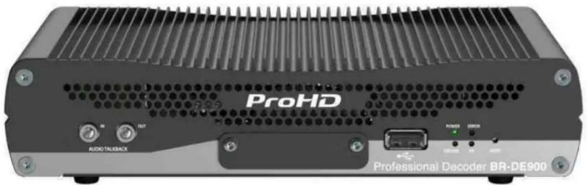
Figure 2-1: BR-DE900 Front Panel
| Connector Label Connector Description | ||
| Audio Talkback IN | Mini Jack Unbalanced | Analog Audio input for Audio Talkback.To be enabled per firmware upgrade. |
| Audio Talkback OUT | Mini Jack Unbalanced | Analog Audio output for Audio Talkback.To be enabled per firmware upgrade. |
| USB Port USB Type A | USB connection. | To set or retrieve network parameters |
| Reset Pin | After boot, a short press will restart the appliance.After boot, a long press (6 seconds minimum) will return the unit to factory settings (erasing all user-stored channel and network settings).Pressing more than 7 seconds while powering up, will cause the appliance to restore the unit to factory firmware settings. | |
| LED/ Port LED Status Description | ||
| Power LED | OffGreenBlinking green once per secondBlinking green twice per second | The appliance is off.The appliance is up and readyThe appliance is startingThe appliance is being upgraded. |
| Error LED | OffRed | All services are running smoothly.An error occurred in one or more services:- Steady on – channel error- Blinking twice per second – abnormal temperature |
| Decode LED | OffGreenBlinking green once per second | No Channel Decoding in progressChannel DecodingThe channel has started, but no input stream was received |
| HD LED | OffGreen | SD stream inputHD stream input. |
ProHD BR-DE900 Rear Panel
| Connector Label Connectors Description | ||
| Ethernet 1 RJ-45 Gigabit | Ethernet for streaming and management. | |
| Ethernet 2 RJ-45 Gigabit | Ethernet for streaming and management | |
| DVB ASI IN BNC DVB ASI input | ||
| DVB ASI OUT BNC DVB ASI output/pass through | ||
| Serial/Audio/Genlock Multi-pin connector | Breakout cable for audio outputs:Digital Audio AES x2Balanced Analog Stereo AudioUnbalanced Analog Stereo AudioGenlock (enabled by firmware upgrade)Serial for KLV/STANAG/CoT output (future) | |
| CVBS BNC Composite output | ||
| SDI1 BNC SDI output | ||
| SDI2 BNC Secondary SDI output | ||
| HDMI HDMI Type A HDMI2.0 output | ||
| POWER 20-50 VDC | Multi-pin connector | Power input. |
Getting Started
In This Chapter
Initial Connection and Setup.... 14
Retrieving or Setting Network Parameters through a USB Thumb Drive.... 16
Initial Connection and Setup
The ProHD BR-DE900 is configured, by default, to use a fixed static IP address for its streaming and management port 1 (labeled "Ethernet1"). Use the default 192.168.1.2 IP address to perform initial login from a computer connected directly to the platform.
To configure the appliance's network settings for the first time:
- Connect a power source to the rear power input port.
-
Connect the network port labeled "Ethernet1" to a computer with network IP configured to 192.168.1.x range with subnet 255.255.255.0 and ensure you can ping the default IP address of the unit to 192.168.1.2.
-
Open a web browser and type the appliance's IP address in the URL field. The login window appears.
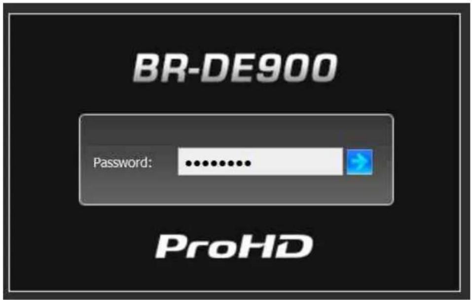
- Type the password (the default password is "jvc1234") and click the blue arrow. The ProHD BR-DE900 interface is loaded.
- From the main menu, select System. The system page opens:
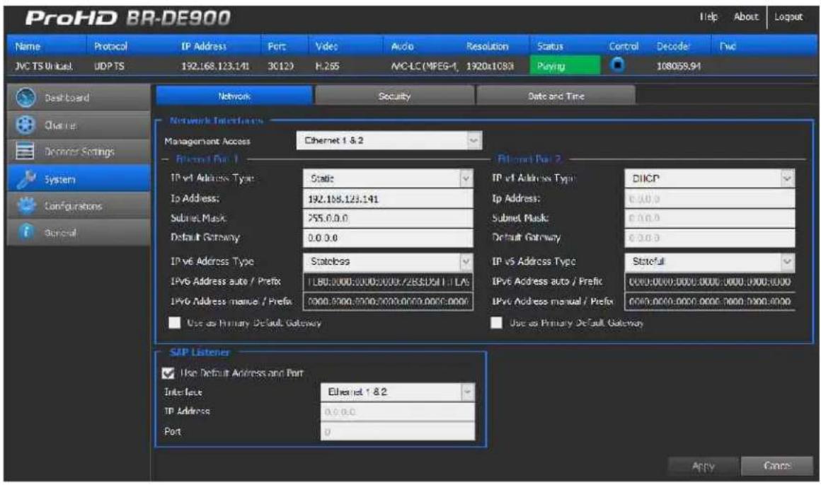
- Set the below parameters required for your network and click Apply.
| Parameter Description | |
| IPv4/ Address Type | Select between Static IP or DHCP+Zeroconf mode.If a Static IP is used, its respective fields must be filled. |
| IP Address Enter the static IP address. | |
| Subnet Mask Enter the subnet mask address. | |
| Default Gateway Enter the default gateway address. | |
| IPv6 Address Type | Refer to The System Page (on page 38) for more information. |
| SAP Listener | Refer to The System Page (on page 38) for more information. |

NOTE:
For more in-to-depth parameter information, refer to The System Page (on page 38).

CAUTION:
When in DHCP mode, ProHD BR-DE900 will receive an IP address automatically from the DHCP server. In order to know the provided address:
- Refer to Retrieving or Setting Network Parameters through a USB Thumb Drive (see "Retrieving or Setting Network Parameters through a USB Thumb Drive (on page 16)" on page ).
- When you change the appliance's IP address to a different subnet you may need to reconfigure your computer network settings to re-connect to the appliance.
Retrieving or Setting Network Parameters through a USB Thumb Drive
To Retrieve Your Network Parameters through a USB Thumb Drive (When ProHD BR-DE900 IP Address is Unknown):
-
Turn ProHD BR-DE900 OFF.
-
Allocate a USB thumb drive and insert it to ProHD BR-DE900 USB port.

NOTE:
USB thumb drive must be formatted in FAT32.
-
Connect the network cable to ProHD BR-DE900 Ethernet port.
-
Insert the USB thumb drive to the ProHD BR-DE900 USB port.
-
Turn ProHD BR-DE900 ON. The network setup file "DecoderNetworkSettings
.txt" is being copied from the appliance to the thumb drive. Wait a few minutes to ensure that the file is being copied properly. -
Remove the USB Thumb drive from the appliance, and insert it to a PC.
-
Open the "DecoderNetworkSettings
.txt" file in the USB thumb drive using any text editor program. -
Read the IP address from the file.
-
Enter the read IP address in the Internet browser URL field. The Log on window appears.
-
Log in.
To Set Network Parameters through a USB Thumb Drive (When ProHD BR-DE900 IP Address is Known):
- Either obtain the "DecoderNetworkSettings
.txt" as detailed above, or from JVC Online Support Portal. This file contains the default IP address of 192.168.1.2. Open it using any text editor program.
- or -
Retrieve the IP address from ProHD BR-DE900 by repeating steps 1 through 7 as described in the section above.
-
Modify any of the listed network parameters, as required, and save the changes. The file name to be used is "DecoderNetworkSettings.txt".
-
Eject the USB thumb drive properly from the PC and insert it to the ProHD BR-DE900 USB port.
-
Turn ProHD BR-DE900 ON. When the boot process is completed, ProHD BR-DE900 will be set with the new IP address.
-
Enter the IP you have set to the Internet browser URL field. The Log on window appears.
-
Log in.
-
Save the file (either on a USB thumb drive or any other place of your choice for future reference. In case ProHD BR-DE900 IP address becomes unknown and needs to be retrieved, this file will be used.
Setup and Operations
In This Chapter
Using the ProHD BR-DE900 Interface....19
The Channel Page 25
The Decoder Settings Page.... 33
The System Page 35
The Configurations Page 39
The General Page 41
Using the ProHD BR-DE900 Interface
ProHD BR-DE900 Functions
The followings are available at all times (regardless which menu item is selected):
- Dashboard frame - top of page from which decoding channel is controlled and monitored.
- Help - offline help/user manual.
- Logout - allows you to log out the application.
- About - provides information about ProHD BR-DE900.
The Main Menu
The ProHD BR-DE900 main menu includes the following items:
- Dashboard - view platform, network and traffic information.
- Channel – view, set and select channel parameters: source streaming protocol, IP address, Ethernet port
• Decoder Settings – set video, audio, decoder parameters - System - view and set appliance's parameters such as network, security, date and time.
- Configurations - allows saving of channel configurations.
- General - view system information such as software version, serial number, and provides restart, factory reset, licensing and firmware upgrade functions.
Dashboard Frame
In the dashboard frame section, you can review the system configuration and parameters.

The Dashboard section displays the following information:
| Parameter Display Description | ||
| Name Channel name defined by the user | ||
| Protocol | UDP TSRTP TSSRTZixiTM BroadcasterZixiTM P2PPro-MPEG | Channel streaming protocol. |
| IP Address | IP address | Displays the stream IP address.While protocol used is ZixiTM Broadcaster or RTSP ES, the streaming server IP address is displayed. |
| Port Displays the stream port number. | While RTSP ES protocol is used, the server port is displayed. | |
| Video | HEVCH.264 | Displays the stream video codec |
| Audio | AAC-LC | Displays the stream audio codec |
| Resolution | Displays the stream video resolution | |
| Status | PlayingStartedStoppedError | Displays the status of the channel.If the stream is not received and ProHD BR-DE900 has been started, "Started" is displayed. |
| Control | [06c6]Play/Stop | Start / Stop the decoder.If the stream is not received and ProHD BR-DE900 has been started, "Started" is displayed. |
| Decoder | Displays the decoder output resolution and frame rate. | |
The Dashboard Page
The dashboard is the main page displaying the appliance's view, and displays network information for both network interfaces as well as an overall stream and traffic summary.
Interfaces being activated and/or used appear in green (see figure below).
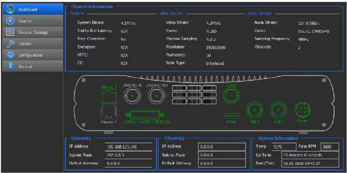
Figure 4-1: The Dashboard page
To view the dashboard parameters:
- From the main menu, select Dashboard. The following parameters are displayed:

NOTE:
The Dashboard page automatically polls the appliance hardware for the latest status of channels, streams and sources. You may also manually refresh the Dashboard page (by either pressing the "F5" key on your keyboard or re-clicking Dashboard), to obtain instantly the current state of the system whenever you configure any of the following parameters: network interfaces, traffic, or rear panel connections.
| Section Description | |
| Channel Information System | System Bitrates- Displays the incoming system network bitrate. In case of several multicast streams on the network, the total bitrate of these streams will be displayed.End to End Latency - N/A - for future usage.Error Correction - Indicates if the stream is protected by either ZixiTM or Pro-MPEG protocol.ZixiTM Statistics: When a ZixiTM channel is decoded, click the info button to access statistical ZixiTM information.Encryption - Indicates if an encrypted stream is being decodedVITC - Indicates if VITC information is detected with the stream (future)CC - Indicates if Closed Captioning information is detected with the stream (future).Video StreamVideo Bitrate - Displays the incoming video bitrate.Codec - Displays the video codec within the stream.Chroma Sampling - Displays the chroma sampling of the stream.Resolution - Displays the stream resolution.Framerate - Displays the stream framerate.Scan Type - Displays if the stream is progressive or interlaced.Audio StreamAudio Bitrate - Displays the incoming audio bitrate.Codec - Display the audio codec within the stream.Sampling Frequency- Display the audio stream sampling rate.Channels - Display the number of audio channels within the stream. |
| Ethernet 1 | IP Address – Displays the Network Interface IP address.Subnet Mask – Displays the Network Interface subnet mask address.Default Gateway – Displays the Network Interface Default Gateway address. |
| Ethernet 2 | IP Address – Displays the Network Interface IP address.Subnet Mask – Displays the Network Interface subnet mask address.Default Gateway – Displays the Network Interface Default Gateway address. |
| System Information | Temperature – Displays the system internal temperature.Fans RPM – Display current fan speedUp Time – Displays the uptime since last reboot.Date/Time – Display Date and Time. |
Zixi™ Statistics Information
- When a Zixi™ channel is decoded, click the info button to access statistical Zixi™ information.
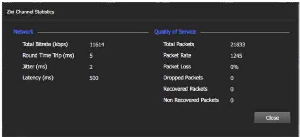
| Parameter Description | |
| Total Bitrate (kbps) | Current bitrate of the incoming channel |
| Round Time Trip (ms) | Two-way delay between the encoder and decoder (RTT) |
| Jitter (ms) | Network jitter |
| Latency (ms) | Stream Latency configured on the encoder side. If the latency set is less than 3 times the RTT value, then Latency value turns red to indicate non-sufficient error recovery buffer size (refer to the note below) |
| Total Packets | Total number of packets already transmitted |
| Packet Rate | Current number of packets per second received |
| Packet Loss | The current percentage of dropped packets between the encoder and decoder (the packet loss is introduced by the network link) |
| Dropped Packets | Total number of packets dropped between the encoder and the decoder due to the network link. The dropped packets are recovered by ZixiTM technology (see below parameters). |
| Recovered Packets | The total number of dropped packets that have been recovered since the beginning of the streaming |
| Non-recoverable Packets | Total number of non-recovered packets since the beginning of the streaming. If the packet loss is lower than 30%, this number should remain zero if the latency set on the encoder or Zixi broadcaster is high enough, meaning no interruption or decoding artifacts were experienced by the viewer. |

NOTE:
For getting sufficient error-recovery, it is recommended to set the Latency on the encoder side at least 3 times larger than the RTT (i.e. Latency >= 3* RTT).
The Channel Page
In the Channel page, a list of channel can be set and saved. The following channel protocols are supported:
- UDP TS
- RTP TS
- RTP ES (RTSP)
- Zixi™ Broadcaster
• Zixi™ P2P (if license is enabled) - Pro-MPEG
SRT
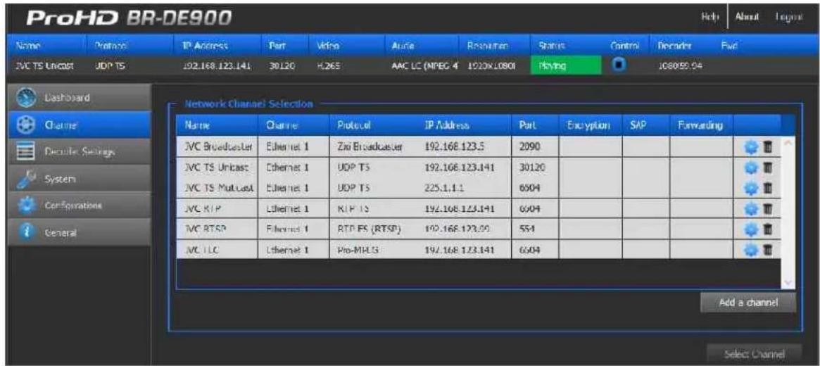
Figure 4-2: The Channel page
To set the channel parameters:
- From the main menu, select Add a Channel.
- The Input Channel Configuration page appears:
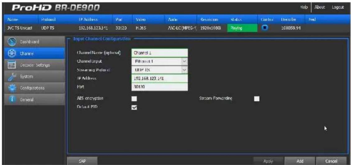
Figure 4-3: The Input Channel Configuration page
- Set the channel fields (name...), as required
-Or-
- Click SAP (bottom left) to display the list of channels announced by the Session Announcement Protocol. SAP channel parameters are automatically configured. Refer to the next section - Input Channel Configuration - for more information.
- Click Add.
- Refer to the Input Channel Configuration description in the next section for more information.

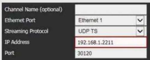
NOTE:
A red frame appears when the entered value is not valid.
-
A new channel is added to the Network Channel Selection List.
-
Select the channel to be decoded row within the list and click Select Channel.
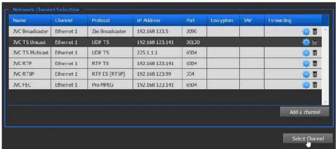
Figure 4-4: The Network Channel Selection window

NOTE:
Channels can be modified or deleted using the settings or bin icons respectively.
Input Channel Configuration
Adding a SAP Channel
ProHD BR-DE900 allows to manually enter the parameters of a channel. It also supports the Session Announcement Protocol (SAP) which allows to detect announced streams on a network for auto channel configuration:

NOTE:
The SAP Listener feature must be enabled for adding a SAP Channel. Refer to The System Page (on page 35) for instructions.
To add a channel using SAP:
- Click SAP in the Input Channel Configuration page:
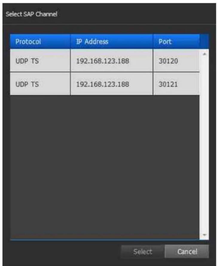
- Select the desired channel row, and click Select.
- The input channel configuration is now populated, add a Channel Name if required (optional parameter).
To manually add a channel:
If a channel does not appear within the SAP list, the channel can be manually set.
For UDP TS and RTP/RTSP channels:
| Parameter Description | |
| Channel Name(Optional) | Enter a Channel Name to differentiate channels within the Channel list. The Channel name is an optional field. |
| Channel Input Select | the Channel Input from which the channel is received. Either Ethernet Port 1, Ethernet Port 2 or DVB-ASI input can be selected. |
| Streaming Protocol Select the required protocol. | |
| IP Address Type the channel IP address. | |
| Port Type the port number. | |
| AES Encryption | Select if you wish to decode an encrypted channel. The AES key value must be entered. |
| Default PID | By default, the decoder selects the first Video and Audio PID to be decoded. In case another PID to be decoded is required, clear the check box and enter the values accordingly. |
| Program PID | Set the program PID to be selected. Only available when Channel Input selected is DVB-ASI. |
| Video PID | Set the Video PID to be decoded |
| Audio1/2 PID | Set the Audio PID to be decoded for each audio pair (1 and 2) |
For RTP ES (RTSP) channel:
In addition to the parameters specified in the table above, type the path of the SDP file residing on the RTP server (Stream Name).

NOTE:
You must click Apply for the new settings to be saved.
Zixi™ Channels

NOTE:
The Zixi™ protocol supports two modes:
• Zixi™ Broadcaster Server.
- Zixi™ P2P: Point-to-Point streaming directly from a JVC encoder. A license is required to support this mode.
When streaming using Zixi™ Broadcaster Server, the BR-DE900 pulls video from one of the server's inputs. Enter the Zixi™ Server IP address and Stream ID / Password for the associated input (do not attempt to create a new output on the server).
When streaming directly from an encoder, enter the stream port to match the encoder settings.
For Zixi™ Broadcaster channel:
| Parameter Description | |
| Channel Name(Optional) | Enter a Channel Name to differentiate channels within the Channel list. Channel name is optional. |
| Ethernet Port Select the Ethernet Port from which the channel is received. | |
| Streaming Protocol Select ZixiTM Broadcaster. | |
| IP Address Type the ZixiTM server IP address. | |
| Port Type the ZixiTM server port. | |
| Stream Name Type the channel name entered in ZixiTM server. | |
| Password (Optional) | Type the password if required. |
| Latency | Type the latency value for the Broadcaster server. It should match the latency value that is set on the ZixiTM Broadcaster. |
For Zixi™ Point-to-point channel (a license is required):
| Parameter Description | |
| Streaming Protocol | Select ZixiTM P2P. |
| Port Type the Channel | port |

NOTE: Zixi™ point-to-point streaming from JVC appliances
Zixi™ Point-to-point license is included when ProHD BR-DE900 is used in conjunction with JVC encoders and cameras. To start using point-to-point Zixi™ streaming between ProHD BR-DE900 and JVC encoders/cameras:
- Verify that the JVC encoder and the BR-DE900 can communicate (the gateways should be properly configured).
- Set Zixi™ as the protocol on both ProHD BR-DE900 and the JVC encoder.
- Set the JVC encoder Target Address by entering ProHD BR-DE900 system IP address (Zixi™ is unicast address only).
- Set the same target port on both ProHD BR-DE900 and JVC encoder.
Start the ProHD BR-DE900 by clicking Play.
Stream forwarding:
ProHD BR-DE900 allows to forward an incoming UDP TS,Zixi™ (P2P or from a Zixi™ Broadcaster) or Pro-MPEG channel to a UDP TS channel over IP (unicast or multicast).
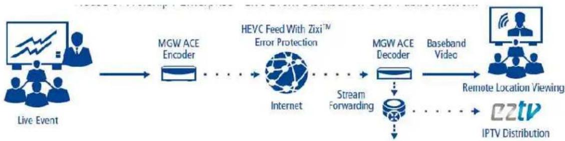
flowchart
graph LR
    A["Live Event"] --> B["MGW ACE Encoder"]
    B --> C["HEVC Feed With Zixi™ Error Protection"]
    C --> D["Internet"]
    D --> E["Stream Forwarding"]
    E --> F["MGW ACE Decoder"]
    F --> G["Baseband Video"]
    G --> H["Remote Location Viewing"]
    H --> I["IPTV Distribution"]
- To activate stream forwarding, click "Stream Forwarding".
2. Enter the following parameters:
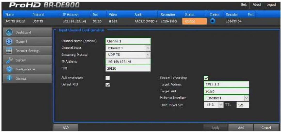
| Parameter Description | |
| Target Address Enter | the Target IP Address |
| Target Port Enter the | Target IP Port number |
| Multicast Interface | When a multicast address is specified in the target field, select the Ethernet Port where the stream shall be transmitted to. |
| UDP Packet Size Select the UDP Packet Size value | |
| TTL Enter the TTL value | |
For Pro-MPEG channel:
| Parameter Description | |
| Channel Name(Optional) | Enter a Channel Name to differentiate channels within the Channel list. Channel name is optional. |
| Ethernet Port Select the Ethernet Port from which the channel is received. | |
| Streaming Protocol Select Pro-MPEG protocol. | |
| IP Address Type the channel IP address. | |
| Port Type the port number of the main input stream. | |
| 1-D Port Number | Type the port number through where columns checksums will be sent. |
| 2-D Port Number | Type the port number through where rows checksums will be sent when the 2-D mode is selected. |
The Decoder Settings Page
In the Decoder Settings page, the below parameters can be set:
• Video
- Audio
- Decoder
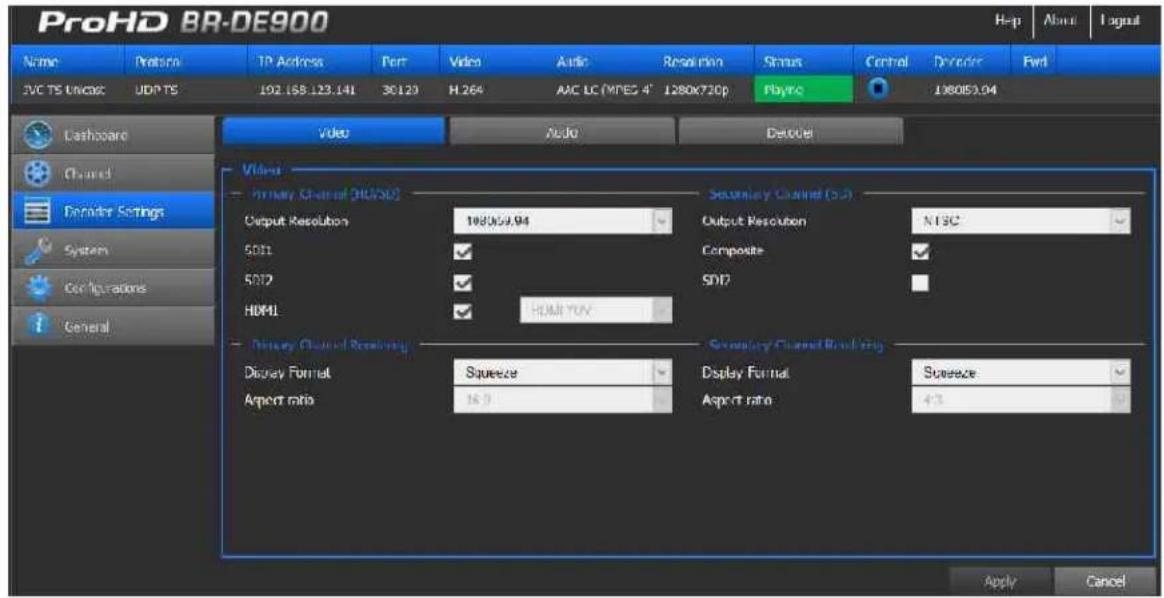
Figure 4-5: The Decoder Settings Video page
To set Video parameters:
This section sets video output settings. Video outputs are split into two channels:
• Primary Channel: SDI1/SDI2 (3G/HD/SD-SDI) and HDMI outputs can be configured.
• Secondary Channel: SDI2 (SD-SDI) and Composite outputs can be configured.

NOTE:
The Secondary channel is a downscaled version of the primary channel.
| Parameter Description | |
| Output Resolution (for each channel) | Select the required resolution from the drop-down list. |
| SDI1 / HDMI SDI2 / Composite | Enable video outputs when the box is selected.SDI2 can be configured as part of the Primary channel or Secondary channel. |
| Display Format Select the preferred display from the drop-down list. | |
| Aspect Ratio Select the aspect ratio from the drop-down list. When "Auto" is selected the aspect ratio is determined according to the aspect ratio of the incoming stream parameter (planned for next versions). | |
To configure Audio Settings:
This section sets audio routing for:
• SDI1/SDI2 and HDMI outputs
- Digital AES 1 and 2 unbalanced outputs. It is possible to set if AES or S/PDIF format is outputted (respectively Consumer or Professional).
- Analog Balanced and Unbalanced audio outputs. The volume can be adjusted independently for the audio analog balanced and unbalanced outputs.
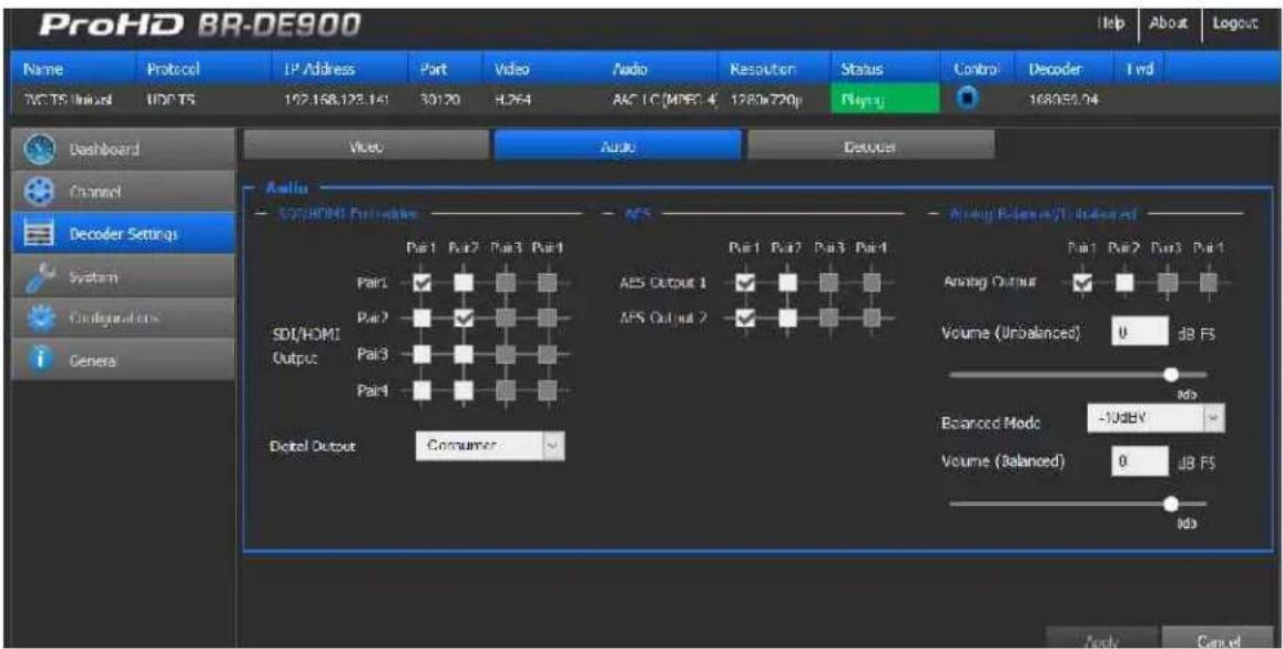
Figure 4-6: The Decoder Settings Audio page
To set the Decoder parameters:
- From the main menu, select Decoder Settings.
- Set the following parameters as required in each section and click Apply.
| Parameter Description | |
| Decoder Clock Source | Select source clock either from:Stream clockGenlock input clock (planned for next versions). |
| Decoder Buffer (ms) | Type the decoder buffer value (0-1500ms). This parameter is used for handling network jitter, allowing smooth playback. The bigger the buffer, the higher the latency.If staggering occurs, increase the buffer value until reaching a smooth decoding.The default buffer value should comply to most streams. |
The System Page
In the System page you set the parameters of the following tabs:
• Network Interfaces
- Date and Time
• Security
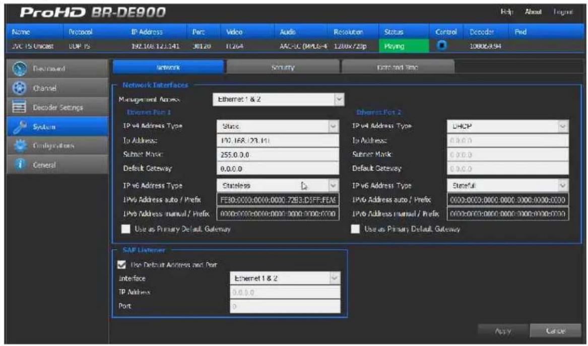
Figure 4-7: The System page
System Parameters:
-
From the main menu, select System.
-
Set the fields in each of the following sections below, as required, and click Apply.
To set the Network Interfaces:
Two network interfaces are available. Each one can be used for either management and/or streaming.
For easier management of the system, Ethernet Port 1 and 2 can be configured in DHCP mode. If DHCP mode is selected, the system will obtain the IP address automatically from the DHCP server.
| Parameter Description | |
| Management Access Select the Ethernet Port used for management (Ethernet Port 1, 2 or 1&2) | |
| IPv4 Address Type Select either Static, DHCP, or DHCP+Zeroconf.Zeroconf allows the unit to get an IP address automatically without DHCP server on the network. To retrieve the system IP address (see "Retrieving or Setting Network Parameters through a USB Thumb Drive (on page 16)" for more information). | |
| IP Address Enter IPv4 Address if Static mode is selected | |
| Subnet Mask Enter Subnet Mask if Static mode is selected | |
| Default Gateway Enter default Gateway if Static mode is selected | |
| IPv6 Address Type | Select either Static, Statefull or Stateless.Static - enter the Static IPv6 address.Stateless - when there is no concern with the exact addresses the host use.Statefull - when more precise control over exact address assignments is required. |
| IPv6 Address auto/prefix Displays the IP/Prefix address. | |
| IPv6 Address manual/prefix Enter a static IP/Prefix address. | |
| Default Gateway Select which Ethernet port settings to be used as the default gateway. | |

NOTE:
You must click Apply for the new settings to be saved.
To set SAP:
| Parameter Description | |
| Use default SAP address and port | Use the default Session Announcement Protocol multicast group and port as per RFC 2974. |
| Interface Select which Ethernet interface listens to the SAP. | |
| IP Address Set the target multicast IP address to which SAP messages will be sent. | |
| Port Set the target port to which SAP messages will be sent. | |

NOTE:
You must click Apply for the new settings to be saved.
To set Security:
| Parameter Description | |
| Current Password Type the current password. | |
| New Password Type the new password (7-16 characters). | |
| Re-Type Password Re-type the new password. | |
| Host Name Host name is "BR-DE900_" where SN is the system serial number. |
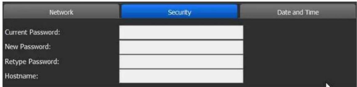
Figure 4-8: The Security page
To set Date and Time:
| Parameter Description | |
| Use NTP Select the box to enable synchronization with the NTP server. | |
| Server Address Enter the NTP server address. | |
| Sync Period Enter the synchronization period. | |
| Date Set the date. | |
| Time Set the time. | |
| Time Zone Set the time zone. | |
| Daylight Saving See instructions below. | |
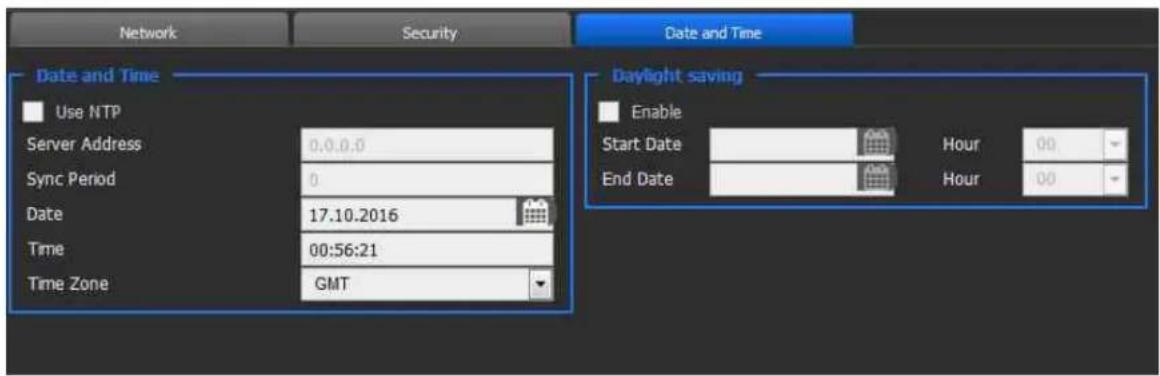
Figure 4-9: The Date and Time page
To set Daylight saving:
| Parameter Description | |
| Enable Select the box to enable daylight saving. | |
| Start Date Set the daylight saving start date. | |
| End Date Set the daylight saving end date. |
The Configurations Page
ProHD BR-DE900 allows you to save screen shots of various configurations to be loaded manually or automatically in the future
In the Configurations page you can add, delete, Activate and Auto start a channel configuration.
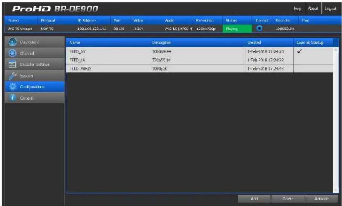
Figure 4-10: The Configurations page
To add a configuration:
1. Click Add.
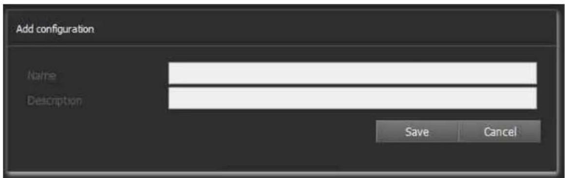
Figure 4-11: The Add Configuration window
-
Type the configuration name and description.
-
Click Save. The new configuration appears on the top row.
To activate a configuration:
- Select the desired configuration row.
- Click Activate to activate the configuration. The activated configuration is applied.
To delete a configuration:
- Select the desired configuration row.
- Click Delete to delete the configuration.
To activate a configuration on boot up:
- Select the desired configuration row.
- Click the desired configuration row under the Load at Startup column. The icon appears in the Load at Startup column in the relevant configuration row.
On next reboot, the selected configuration will load automatically.

NOTE:
- The configuration saves all ProHD BR-DE900 parameters and status. If the configuration was saved while in Stop mode, the system will return to that state while loading the configuration.
- For the appliance to automatically start decoding at boot up, ensure the configuration is saved while "Playing" a stream.
The General Page
In the General page you can view appliance related parameters and perform firmware upgrades.
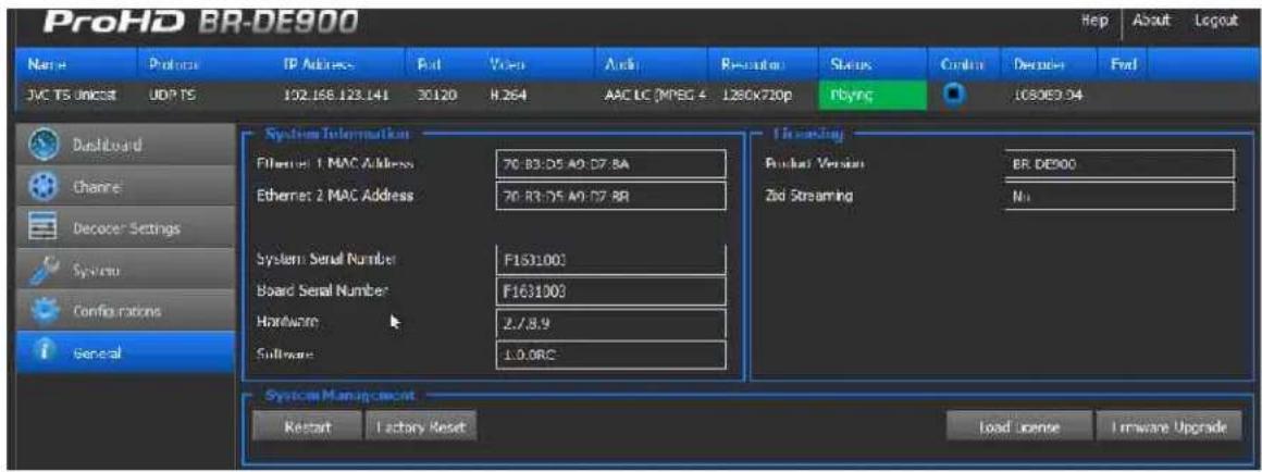
Figure 4-12: The General page
System Information parameters:
| Parameter Description | |
| Ethernet 1 MAC Address Displays the Network Interface #1 MAC Address. | |
| Ethernet 2 MAC Address Displays the Network Interface #2 MAC Address. | |
| System Serial Number Displays the system serial number. | |
| Board Serial Number Displays the video board serial number. | |
| Hardware Displays the current hardware revision. | |
| Software Displays the active software version. | |
Licensing:
| Parameter Description | |
| Product Version Displays the Product version name | |
| ZixiTM Streaming Displays the ZixiTM P2P license status | |
To restart the appliance:
- Click Restart to restart the appliance.
To restore factory settings:
- Click Factory Reset to reset all parameters to default factory values.

NOTE:
- The Factory Reset function will return the unit to its default IP settings: 192.168.1.2 with subnet mask 255.255.255.0 (Ethernet1) and DHCP mode for Ethernet 2.
- To connect from Ethernet 1, if you are connected to the unit from a PC on a different subnet, reconfigure your computer to the 192.168.1.x subnet to gain access to the unit and modify its settings for network use.
- To connect from Ethernet2, ensure you are connected to DHCP router, and retrieve the IP address of ProHD BR-DE900 using the USB key procedure (or define an IP address to ProHD BR-DE900 based on its MAC Address).
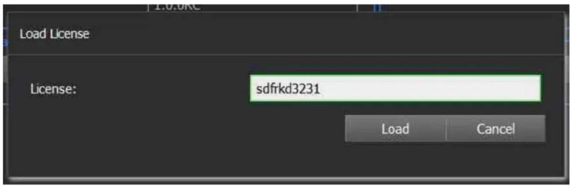
To load a Zixi™ license:
- Click Load License to load the Zixi™ license number.
- To get a Zixi™ license number, contact your JVC sales representative. The System Serial Number will be requested to generate the license
Firmware Upgrade
In This Chapter
Upgrading the Firmware.... 44
Upgrading the Firmware
Important Notes Prior to Upgrade
JVC periodically releases new firmware versions that include critical updates as well as feature enhancements.
ProHD BR-DE900 firmware and software upgrade process involves uploading a .TAR file within the unit HTTPS user interface, allowing the unit to extract the required files and perform internal updates. Uploading time of the upgrade file can take up to few minutes and may vary from one computer to another. It also depends on network speed and the connection's quality between the computer and the ProHD BR-DE900 appliance. On regular LAN, it takes only few seconds.
During the upgrade, while the file is uploaded, the web based HTTPS interface polls the unit status. This polling attempt occurs also during the actual execution of the upgrade inside the appliance. To avoid interruption to the upgrade process, do not close the active browser window used for uploading the file.
Read carefully the step-by-step procedure below and pay extra attention to notes and warnings.
To upgrade ProHD BR-DE900 Firmware version:
- Send JVC your upgrade firmware request.
- Click the General tab.
- Click Firmware Upgrade. The Load Firmware window appears.
-
Click Browse. A browser window opens.
-
Select the appropriate *.tar file and click Load. The Upgrade window appears on the screen, indicating the progress of the upgrade process:
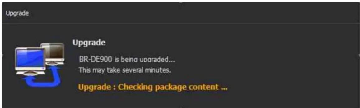
The loading process takes from a few seconds to few a minutes, depending on your available network bandwidth. When loading completes, the Upgrade message disappears.
- ProHD BR-DE900 reboots. Reconnect using the previously used IP address, and enter your login information.
In the General screen, verify that the upgrade was successful by inspecting the Software Version field.
Technical Specifications
In This Chapter
Compliance 46
Environmental 46
Physical 46
Functional Description 46
Compliance
• FCC Part 15, Class A
• CE
ICES-003
• RoHS
Environmental
• Operating Temperatures: 0 °C to +50 °C (-4 °F to 122 °F)
• Relative Humidity: 5% to 95% (non-condensing)
Physical
- Dimensions: 1.65" H x 7.95" W x 4.60" D (42.4 mm H x 202 mm W x 117.5 mm D)
• Weight: 2.40 lb (1.1 kg)
• Enclosure: Industrial-grade - Mounting holes for seamless installation in vehicles / onto flat surfaces
Functional Description
Stream Input support:
Video Decoder- HEVC (H.265)
MPEG-H HEVC (ISO/IEC 23008-2) Modes:
• Profile/Level: up to Main422 10@L4.1 High Tier
• Color sampling & bit-depth: up to 4:2:2 / 10 bits
- Bit Rate: up to 50Mbps
• Frame Rate: 1-60 fps.
- Input Resolutions: from CIF up to 1920x1080
Video Decoder- H.264 (HEVC)
MPEG-4 AVC/H.264 (ISO\IEC 14496-10 MPEG-4 AVC -Rec. ITU-T H.264)
• Profile/Level: up to Hi10@L4.2
• Color sampling / Bit-depth: up to 4:2:2 / 10 bits
- Bit Rate: up to 100Mbps
• Frame Rate: 1-60 fps.
- Input Resolutions: from CIF up to 1920x1080
Audio Decoder
• MPEG-4 AAC-LC (ISO/IEC 14496-3)
- Up to 2x stereo channel
• Sample Rate: 48kHz
- Bit Rate: 16-192kbs
Network Protocols
- UDP TS
- RTP TS
- RTP ES (RTSP)
- Zixi™ Error-Correction (HEVC and H.264) – Zixi™ P2P and Broadcaster modes with stream forwarding feature.
• RTP TS with ProMPEG Forward Error Correction (SMPTE 2022)
Security
• Real-time AES decryption for video, audio and metadata
Network Interfaces
• 2x Gigabit Ethernet ports for management and/or streaming
• DVB-ASI Input and Output
Video Outputs (Rear Panel)
- 1 x 3G/HD-SDI/SD-SDI (SMPTE 259M-C, SMPTE 292M, SMPTE 274M, SMPTE 296M, SMPTE 424M, SMPTE 425M-A) (12G-SDI activated by firmware update and license option)
- 1 x HDMI v2.0
• 1x SD-SDI (SMPTE 259M-C)
• 1x Composite (CVBS)
Output Resolutions / frame rates support:
• 1920x1080p @ 60, 59.94, 50, 30, 29.97, 25, 24, 23.976
• 1920x1080i @ 60, 59.94, 50 Hz
• 1280x720p @ 60, 59.94, 50, 30, 29.97, 25
• 720x480i @ 59.94 Hz (NTSC)
• 720x576i @ 50 Hz (PAL)
Audio Outputs
• SDI Embedded audio (PCM support)
• HDMI Embedded audio (PCM support)
• 2x AES3 Digital Audio (BNC Female)
• 1 x Analog unbalanced stereo audio, AC-coupled (RCA Female)
• 1 x Balanced analog stereo audio (XLR Male)
Talkback Audio (front panel)
• Input : 1 x Analog unbalanced stereo audio, AC-coupled (Mini Jack)
• Output 1 x Analog unbalanced stereo audio, AC-coupled (Mini Jack)
Warranty
Limited Hardware Warranty Terms
Subject to the terms and conditions specified below your JVC product (the "Product") is warranted against defects in material and workmanship (the "Warranty") for a period of 12 (twelve) months following the Delivery Date (the "Warranty Period"). The Warranty provided to you hereunder supersedes any warranty which may be provided to you by the original manufacturer of the Product.
JVC (collectively "company") will repair or replace (at its option) any defective part during the Warranty Period, provided that (i) the Warranty remains in force. Your dated sales receipt or invoice shall be considered as the delivery date of the Product form JVC's premises to your designated address (the "Delivery Date"); (ii) your Product unit carries a serial number on its rear panel; (iii) you received from JVC Customer Service department a Return Materials Authorization (RMA) number. No Product unit will be accepted for repair without RMA number; and (iv) the entire Product unit is returned to the company by prepaid shipping in JVC's original packaging.
JVC will not be responsible for (i) any damages resulting from the use, maintenance or installation of any Product; or (ii) for the incorporation of any spare or replacement parts not approved by the company.
Without limiting the generality of the foregoing, The company reserves the right to refuse to provide any services under the Warranty for any Product that, in the company opinion, has been subjected to any abnormal electrical, mechanical, or environmental abuse, or shows signs of modification by an unauthorized person or company. Call your local distributor or reseller for out-of-warranty repair charge estimates prior to returning a product.
You acknowledge that the product licensed or sold hereunder, which may include technology and software, are subject to the export control laws and regulations of the United States ("U.S.") and/or any other country in which the product is received. You agree that you will not knowingly transfer, divert, export or re-export, directly or indirectly, the product, including the software, the software source code, or technical data (as defined by the U.S. Export Administration Regulations) restricted by such regulations or by other applicable national regulations to any person, firm, entity country or destination to which such transfer, diversion, export or re-export is restricted or prohibited by U.S. or other applicable law, without obtaining prior authorization from the U.S.
Department of Commerce and other competent government authorities to the extent required by those laws.
Index
A
About This Manual • 8
C
Compliance • 46
Copyright Notice • vi
D
Dashboard Frame • 20
Declaration of Conformity and Regulatory
Compliance • iv
E
Environmental • 46
F
Firmware Upgrade • 8, 44
Functional Description • 47
G
General • 8
Getting Started • 8, 14
|
I/O Specifications • 11
Initial Connection and Setup • 14
Input Channel Configuration • 28
M
Manual Structure and Use • 8
0
Open Source Documentation • vii
P
Physical • 46
ProHD BR-DE900 Front Panel • 11
ProHD BR-DE900 Overview • 8, 9
ProHD BR-DE900 Rear Panel • 13
R
Retrieving or Setting Network Parameters through a USB Thumb Drive • 16, 17, 37
S
Safety Instructions • iii
Setup and Operations • 8, 19
System Requirements • 10
T
Technical Specifications • 8, 46
The Channel Page • 25
The Configurations Page • 40
The Dashboard Page • 21
The Decoder Settings Page • 33
The General Page • 42
The Main Menu • 20
The Product • 9
The System Page • 16, 28, 36
U
Upgrading the Firmware • 44
Using the ProHD BR-DE900 Interface • 19
W
Warranty • 49
- ProHD BR-DE900
- HEVC and H.264 Decoding Appliance
- User Manual
- Contents
- Safety Instructions
- When using ProHD BR-DE900
- Declaration of Conformity and Regulatory Compliance
- WARNING:
- Canada: ICES-003
- Copyright Notice
- Open Source Documentation
- About This Manual
- General
- Manual Structure and Use
- ProHD BR-DE900 Overview
- The Product
- • Pro-MPEG SMPTE-2022
- • Zixi™
- SRT - Secure Reliable Transport protocol
- The ProHD BR-DE900 package includes:
- System Requirements
- Operating System:
- Internet Browser:
- I/O Specifications
- ProHD BR-DE900 Front Panel
- Getting Started
- Initial Connection and Setup
- To configure the appliance's network settings for the first time:
- NOTE:
- CAUTION:
- Retrieving or Setting Network Parameters through a USB Thumb Drive
- Setup and Operations
- In This Chapter
- Using the ProHD BR-DE900 Interface
- ProHD BR-DE900 Functions
- The Main Menu
- Dashboard Frame
- The Dashboard Page
- To view the dashboard parameters:
- Zixi™ Statistics Information
- The Channel Page
- To set the channel parameters:
- Input Channel Configuration
- Adding a SAP Channel
- To add a channel using SAP:
- To manually add a channel:
- For RTP ES (RTSP) channel:
- Zixi™ Channels
- NOTE: Zixi™ point-to-point streaming from JVC appliances
- Stream forwarding:
- Enter the following parameters:
- The Decoder Settings Page
- To set Video parameters:
- To configure Audio Settings:
- To set the Decoder parameters:
- The System Page
- System Parameters:
- To set the Network Interfaces:
- The Configurations Page
- To add a configuration:
- Click Add.
- To activate a configuration:
- To delete a configuration:
- To activate a configuration on boot up:
- The General Page
- To restart the appliance:
- To restore factory settings:
- To load a Zixi™ license:
- Firmware Upgrade
- Upgrading the Firmware
- Important Notes Prior to Upgrade
- To upgrade ProHD BR-DE900 Firmware version:
- Technical Specifications
- Compliance
- Environmental
- Physical
- Functional Description
- Stream Input support:
- Video Decoder- HEVC (H.265)
- Video Decoder- H.264 (HEVC)
- Audio Decoder
- Network Protocols
- Security
- Network Interfaces
- Video Outputs (Rear Panel)
- Output Resolutions / frame rates support:
- Audio Outputs
- Talkback Audio (front panel)
- Warranty
- Limited Hardware Warranty Terms
- Index
- A
- C
- D
- E
- F
- G
- |
- M
- 0
- P
- R
- S
- T
- U
- W
Brand : JVC
Model : ProHD BR-DE900
Category : Uncategorized