
CSP18GREGAL - Air conditioner CORBERO - Free user manual and instructions
Find the device manual for free CSP18GREGAL CORBERO in PDF.


| Product Type | Split-type air conditioner (inverter) |
| Model | CSP18GREGAL |
| Brand | Corbero |
| Cooling Capacity | 18,000 Btu/h |
| Heating Capacity | 18,000 Btu/h (heat pump) |
| Refrigerant | R32 (flammable) |
| Power Supply | 220-240 V ~ 50/60 Hz |
| Indoor Unit Dimensions (W x H x D) | Approx. 970 x 300 x 215 mm |
| Indoor Unit Weight | Approx. 12 kg |
| Outdoor Unit Dimensions (W x H x D) | Approx. 800 x 550 x 300 mm |
| Outdoor Unit Weight | Approx. 30 kg |
| Operating Modes | Cool, Heat, Fan, Dry, Auto |
| Special Functions | Turbo, ECO, Sleep, Mute, Timer, Swing, I Feel, 8°C Heating |
| Airflow Direction Control | 4-way swing (up/down and left/right) |
| Filter | Washable air filter |
| Smart Control | WiFi via SmartLife app (iOS/Android) |
| Remote Control | Included (2 x AAA batteries) |
| Maximum Pipe Length | 25 m |
| Maximum Height Difference | 10 m |
| Additional Refrigerant Charge | 25 g/m (for pipe length >5 m) |
| Minimum Room Area for Installation | 4 m² (due to R32 refrigerant) |
| Warranty | 3 years on unit, 7 years on compressor (Spain/Portugal) |
Frequently Asked Questions - CSP18GREGAL CORBERO
User questions about CSP18GREGAL CORBERO
0 question about this device. Answer the ones you know or ask your own.
Ask a new question about this device
Download the instructions for your Air conditioner in PDF format for free! Find your manual CSP18GREGAL - CORBERO and take your electronic device back in hand. On this page are published all the documents necessary for the use of your device. CSP18GREGAL by CORBERO.
USER MANUAL CSP18GREGAL CORBERO
natural_image
Line drawing of a rectangular appliance with a flat top and side panel (no text or symbols)CSP09GREGAL
CSP12GREGAL
CSP18GREGAL
CSP24GREGAL

natural_image
Diagram of an open mobile phone showing internal components and battery pack (no text or labels)natural_image
Simple line icon of an open book with a lowercase 'i' symbol on the right page (no text or labels)natural_image
Illustration of an open book with a wrench resting on it (no text or symbols)| Tipo inversor modelo capacidad (Btu/h) | 9k | 12k | 18k | 24k | |
| área de la zona | |||||
| Cable de alimentación eléctrica | N | 1.5mm^2 | 1.5mm^2 | 1.5mm^2 | 2.5mm^2 |
| L | 1.5mm^2 | 1.5mm^2 | 1.5mm^2 | 2.5mm^2 | |
| 1.5mm^2 | 1.5mm^2 | 1.5mm^2 | 2.5mm^2 | ||
| Cable de conexión | N | 0.75mm^2 | 0.75mm^2 | 0.75mm^2 | 0.75mm^2 |
| L or (L) | 0.75mm^2 | 0.75mm^2 | 0.75mm^2 | 0.75mm^2 | |
| 1 | 0.75mm^2 | 0.75mm^2 | 0.75mm^2 | 0.75mm^2 | |
| 0.75mm^2 | 0.75mm^2 | 0.75mm^2 | 0.75mm^2 | ||

Nota:
natural_image
Diagram of a coiled tube with two connectors and directional arrows indicating rotation (no text or symbols)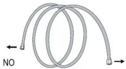
natural_image
Diagram of a coiled tube with directional arrows indicating movement (no text or symbols)natural_image
Two types of electrical connectors shown in line drawings: threaded and hexagonal (no text or symbols)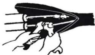
natural_image
Illustration of hands pulling a curved object with motion lines (no text or symbols)natural_image
Technical line drawing of an internal air conditioner unit with no visible text or symbolsPuertos de drenaje
natural_image
Simple line drawing of a door with a brick wall and a cable, no text or symbols present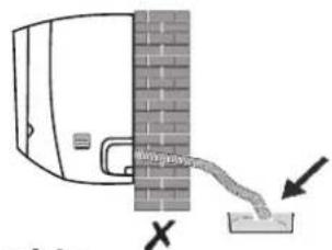
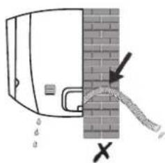
Paso6: Conecte el cable
natural_image
Pure diagram of a pipe or tube with a circular loop and textured fill, no text or symbols presentnatural_image
Line drawing of a dual-panel air conditioner unit with fan blades and ventilation slots (no text or symbols)natural_image
Line drawing of a rectangular air conditioner unit (no text or symbols)CSP09GREGAL
CSP12GREGAL
CSP18GREGAL
CSP24GREGAL

natural_image
Diagram of an open mobile phone showing internal components and battery pack (no text or labels)Liga/desliga o ecrã LED no painel.

natural_image
Simple line icon of an open book with an information symbol (no text or numbers present)
natural_image
Simple line drawing of an open book with a wrench on the cover (no text or symbols)| TIPO INVERSOR modelo capacidade (Btu/h) | 9k | 12k | 18k | 24k | |
| área seccional | |||||
| Cabo de alimentação | N | 1.5mm^2 | 1.5mm^2 | 1.5mm^2 | 2.5mm^2 |
| L | 1.5mm^2 | 1.5mm^2 | 1.5mm^2 | 2.5mm^2 | |
| [KSZZ] | 1.5mm^2 | 1.5mm^2 | 1.5mm^2 | 2.5mm^2 | |
| Cabo de conexão | N | 0.75mm^2 | 0.75mm^2 | 0.75mm^2 | 0.75mm^2 |
| L or (L) | 0.75mm^2 | 0.75mm^2 | 0.75mm^2 | 0.75mm^2 | |
| 1 | 0.75mm^2 | 0.75mm^2 | 0.75mm^2 | 0.75mm^2 | |
| [TGHS] | 0.75mm^2 | 0.75mm^2 | 0.75mm^2 | 0.75mm^2 | |
natural_image
Diagram of a flexible hose with two connectors and directional arrows indicating rotation (no text or symbols)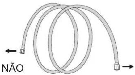
natural_image
Two types of threaded fasteners shown side by side, one with threaded end and the other with a hexagonal nut (no text or symbols)
natural_image
Illustration of a hand holding a tool interacting with a blade-like object (no text or symbols)natural_image
Technical line drawing of an internal air conditioner unit showing internal compartments and ventilation ducts (no text or labels)Portas de drenagem
natural_image
Diagram of a pipe connection between two vertical containers (no text or symbols)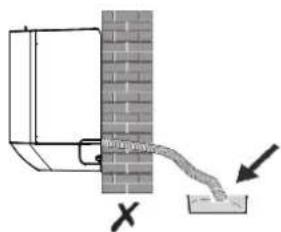
natural_image
Diagram of a pipe connection with a wall and outlet, showing directional arrows (no text or symbols)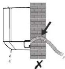
natural_image
Diagram of a pipe with two circular loops above a cylindrical container (no text or symbols)natural_image
Technical line drawing of a mechanical assembly with no visible text or symbolsnatural_image
Line drawing of a dual-panel air conditioner unit with fan blades and control panel (no text or symbols)Coloque 4 placas de borracha (opcionais)
natural_image
Line drawing showing the installation of a two-story HVAC fan with a hand inserting a cable to the front panel (no text or symbols present)Retire a tampa de válvula
Tubos de conexão
natural_image
Mechanical diagram showing a lever mechanism with a bolt and nut assembly (no text or labels)SPLIT TYPE AIR CONDITIONER INSTRUCTION MANUAL
natural_image
Line drawing of a rectangular air conditioner unit (no text or symbols)CSP09GREGAL
CSP12GREGAL
CSP18GREGAL
CSP24GREGAL
This instruction manual contains important information and recommendations that we would ask you to comply with to obtain best results from air conditioner.
Thank you once again.
CONTENTS
SAFETY PRECAUTIONS ....1
NAME OF PARTS 4
REMOTE CONTROL 6
OPERATION INSTRUCTIONS ......13
INSTRUCTION FOR SERVICING(R32) 14
INSTALLATION PRECAUTIONS ....19
INDOOR UNIT INSTALLATION 22
OUTDOOR UNIT INSTALLATION 27
TEST OPERATION 30
MAINTENANCE 32
TROUBLESHOOTING 33
SAFETY PRECAUTIONS
SAFETY RULES AND RECOMMENDATIONS FOR THE INSTALLER
- Read this guide before installing and using the appliance.
- During the installation of the indoor and outdoor units the access to the working area should be forbidden to children. Unforeseeable accidents could happen.
- Make sure that the base of the outdoor unit is firmly fixed.
- Check that air cannot enter the refrigerant system and check for refrigerant leaks when moving the air conditioner.
- Carry out a test cycle after installing the air conditioner and record the operating data.
- Protect the indoor unit with a fuse of suitable capacity for the maximum input current or with another overload protection device.
- Ensure that the mains voltage corresponds to that stamped on the rating plate. Keep the switch or power plug clean. Insert the power plug correctly and firmly into the socket, thereby avoiding the risk of electric shock or fire due to insufficient contact.
- Check that the socket is suitable for the plug, otherwise have the socket changed.
- The appliance must be fitted with means for disconnection from the supply mains having a contact separation in all poles that provide full disconnection under over voltage category III conditions, and these means must be incorporated in the fixed wiring in accordance with the wiring rules.
- The air conditioner must be installed by professional or qualified persons.
- Do not install the appliance at a distance of less than 50 cm from inflammable substances (alcohol, etc.) Or from pressurized containers (e.g. spray cans).
- If the appliance is used in areas without the possibility of ventilation, precautions must be taken to prevent any leaks of refrigerant gas from remaining in the environment and creating a danger of fire.
- The packaging materials are recyclable and should be disposed of in the separate waste bins. Take the air conditioner at the end of its useful life to a special waste collection center for disposal.
- Only use the air conditioner as instructed in this booklet. These instructions are not intended to cover every possible condition and situation. As with any electrical household appliance, common sense and caution are therefore always recommended for installation, operation and maintenance.
- The appliance must be installed in accordance with applicable national regulations.
- Before accessing the terminals, all the power circuits must be disconnected from the power supply.
- The appliance shall be installed in accordance with national wiring regulations.
- This appliance can be used by children aged from 8 years and above and persons with reduced physical, sensory or mental capabilities or lack of experience and knowledge if they have been given supervision or instruction concerning use of the appliance in a safe way and understand the hazards involved. Children shall not play with the appliance. Cleaning and user maintenance shall not be made by children without supervision.
SAFETY PRECAUTIONS
SAFETY RULES AND RECOMMENDATIONS FOR THE INSTALLER
- Do not try to install the conditioner alone, always contact specialized technical personnel.
- Cleaning and maintenance must be carried out by specialized technical personnel. In any case disconnect the appliance from the mains electricity supply before carrying out any cleaning or maintenance.
- Ensure that the mains voltage corresponds to that stamped on the rating plate. Keep the switch or power plug clean. Insert the power plug correctly and firmly into the socket, thereby avoiding the risk of electric shock or fire due to insufficient contact.
- Do not pull out the plug to switch off the appliance when it is in operation, since this could create a spark and cause a fire, etc.
- This appliance has been made for air conditioning domestic environments and must not be used for any other purpose, such as for drying clothes, cooling food, etc.
- Always use the appliance with the air filter mounted. The use of the conditioner without air filter could cause an excessive accumulation of dust or waste on the inner parts of the device with possible subsequent failures.
- The user is responsible for having the appliance installed by a qualified technician, who must check that it is earth in accordance with current legislation and insert a thermos magnetic circuit breaker.
- The batteries in remote controller must be recycled or disposed of properly. Disposal of Scrap Batteries --- Please discard the batteries as sorted municipal waste at the accessible collection point.
- Never remain directly exposed to the flow of cold air for a long time. The direct and prolonged exposition to cold air could be dangerous for your health. Particular care should be taken in the rooms where there are children, old or sick people.
- If the appliance gives off smoke or there is a smell of burning, immediately cut off the power supply and contact the Service Center.
- The prolonged use of the device in such conditions could cause fire or electrocution.
- Have repairs carried out only by an authorised Service Centra of the manufacturer. Incorrect repair could expose the user to the risk of electric shock, etc.
- Unhook the automatic switch if you foresee not to use the device for a long time. The airflow direction must be properly adjusted.
- The flaps must be directed downwards in the heating mode and upwards in the cooling mode.
- Ensure that the appliance is disconnected from the power supply when it will remain inoperative for a long period and before carrying out any cleaning or maintenance.
- Selecting the most suitable temperature can prevent damage to the appliance.
SAFETY PRECAUTIONS
SAFETY RULES AND PROHIBITIONS
- Do not bend, tug or compress the power cord since this could damage it. Electrical shocks or fire are probably due to a damaged power cord. Specialized technical personnel only must replace a damaged power cord.
- Do not use extensions or gang modules.
- Do not touch the appliance when barefoot or parts of the body are wet or damp.
- Do not obstruct the air inlet or outlet of the indoor or the outdoor unit. The obstruction of these openings causes a reduction in the operative efficiency of the conditioner with possible consequent failures or damages.
- In no way alter the characteristics of the appliance.
- Do not install the appliance in environments where the air could contain gas, oil or sulphur or near sources of heat.
- This appliance is not intended for use by persons (including children) with reduced physical, sensory or mental capabilities, or lack of experience and knowledge, unless they have been given supervision or instruction concerning use of the appliance by a person responsible for their safety.
- Do not climb onto or place any heavy or hot objects on top of the appliance.
- Do not leave windows or doors open for long when the air conditioner is operating.
- Do not direct the airflow onto plants or animals.
- A long direct exposition to the flow of cold air of the conditioner could have negative effects on plants and animals.
- Do not put the conditioner in contact with water. The electrical insulation could be damaged and thus causing electrocution.
- Do not climb onto or place any objects on the outdoor unit.
- Never insert a stick or similar object into the appliance. It could cause injury.
- Children should be supervised to ensure that they do not play with the appliance. If the supply cord is damaged, it must be replaced by the manufacturer, its service agent or similarly qualified persons in order to avoid a hazard.
NAME OF PARTS
Indoor Unit
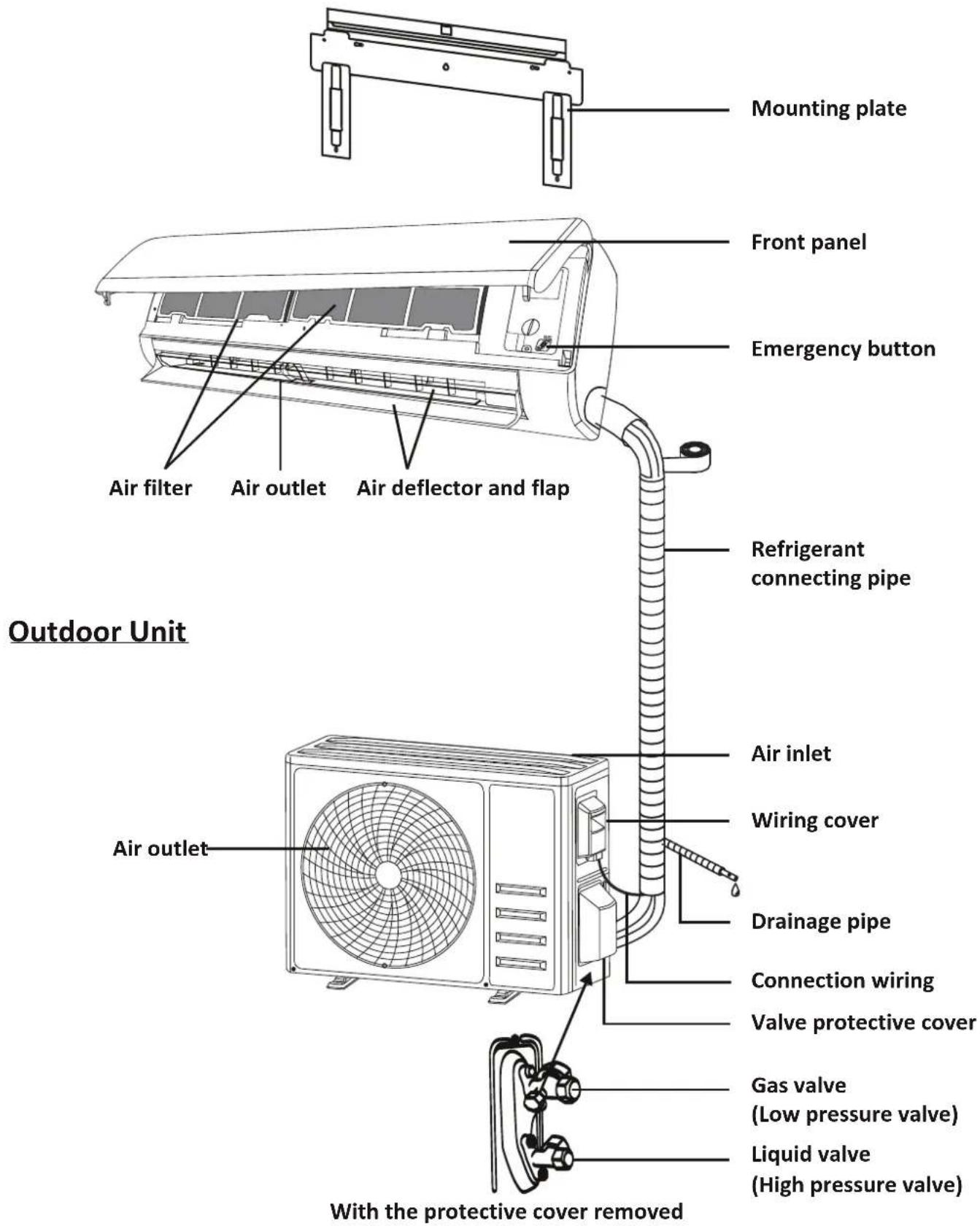
Note: This figure shown may be different from the actual object. Please take the latter as the standard.
NAME OF PARTS
Indoor Display
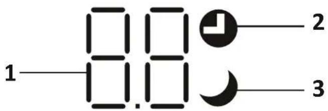
| No. | LED | Function |
| 1 |  | Indicator for Timer, temperature and Error codes. |
| 2 |  | Lights up during Timer operation. |
| 3 | [AYBY] | SLEEP mode |

The shape and position of switches and indicators may be different according to the model, but their function is the same.
REMOTE CONTROL
Remote control DISPLAY
| No. | Symbols | Meaning |
| 1 |  | Battery indicator |
| 2 | [K7Y0] | Auto Mode |
| 3 |  | Cooling Mode |
| 4 |  | Dry Mode |
| 5 |  | Fan only Mode |
| 6 |  | Heating Mode |
| 7 | [TX93] | ECO Mode |
| 8 |  | Timer |
| 9 |  | Temperature indicator |
| 10 | 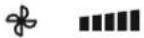 | Fan speed:Auto/ low/ low-mid/ mid/ mid-high/ high |
| 11 | [T80Y] | Mute function |
| 12 |  | TURBO function |
| 13 |  | Up-down auto swing |
| 14 |  | Left-right auto swing (Optional) |
| 15 |  | SLEEP function |
| 16 | [HCK9] | Health function |
| 17 |  | I FEEL function |
| 18 |  | 8^ heating function |
| 19 |  | Signal indicator |
| 20 |  | Gentle wind |
| 21 |  | Child-Lock |
| 22 |  | Display ON/OFF |
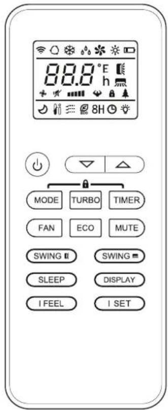

The display and some functions of the remote control may vary according to the model.
REMOTE CONTROL
| No. | Button | Function |
| 1 | To turn on/off the air conditioner . | |
| 2 | ^ | To decrease temperature, or Timer setting hours. |
| 3 | √ | To increase temperature, or Timer setting hours. |
| 4 | MODE | To select the mode of operation (AUTO, COOL, DRY, FAN, HEAT). |
| 5 | ECO | To activate/deactivate the ECO function. |
| 6 | TURBO | To activate/deactivate the TURBO function. |
| 7 | FAN | To select the fan speed of auto/low/mid/high. |
| 8 | TIMER | To set the time for timer on/off. |
| 9 | SLEEP | To switch-on/off the function SLEEP. |
| 10 | DISPLAY | To switch-on/off the LED display. |
| 11 | SWING ◊ | To stop or start horizontal louver movement or set the desired up/down air flow direction. |
| 12 | MUTE | To switch-on/off the MUTE function. |
| 13 | MODE + TIMER | To activate/deactivate the CHILD-LOCK function. |
| 14 | I SET | To memory the setting temperature, setting mode and setting fan speed as you need. |
⚠ The display and some functions of the remote control may vary according to the model.
The shape and position of buttons and indicators may vary according to the model, but their function is the same.
⚠ The unit confirms the correct reception of each button with the beep.
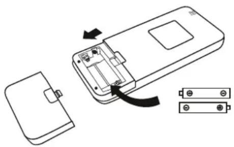
Replacement of Batteries
Remove the battery cover plate from the rear of the remote control, by sliding it in direction as the arrow.
Install the batteries according the direction (+ and -) shown on the Remote Control.
Reinstall the battery cover by sliding it into place.

Use 2 pieces LRO3 AAA (1.5V) batteries.
Do not use rechargeable batteries.
Replace the old batteries with new ones of the same type when the display is no longer legible.
Do not dispose batteries as unsorted municipal waste.
Collection of such waste separately for special treatment is necessary.
natural_image
Diagram of an open mobile phone showing internal components and battery pack (no text or labels)
For some model, each time when insert the batteries in the remote controller for the first time, you can set the Cooling only or Heating pump control type. As soon as you insert the batteries, turn off the remote controller, and operate as below.
- Long press the MODE button, until the (*) icon flash, to set the Cooling only type.
- Long press the MODE button, until the (☀️) icon flash, to set the Heating pump type.
Note: If you set the remote control in cooling mode, it will not be possible to activate the heating function in units with a heating pump. If you need to reset, take out the batteries and install again.

For some model of remote controller, you can program the temperature display between ^ C and ^ F.
- Press and hold the TURBO button over 5 seconds to get into the change mode;
- Press and hold the TURBO button, until it switch to °C and °F;
- Then release the pressing and wait for 5 seconds, the function will be selected.
Note:
- Direct the remote control toward the Air conditioner.
- Check that there are no objects between the remote control and the Signal receptor in the indoor unit.
- Never leave the remote control exposed to the rays of the sun.
- Keep the remote control at a distance of at least 1m from the television or other electrical appliances.
REMOTE CONTROL
COOLING MODE
COOL
The cooling function allows the air conditioner to cool the room and reduce Air humidity at the same time.
To activate the cooling function (COOL), press the MODE button until the symbol ✿ appears on the display.
With the button √ or ∧ set a temperature lower than that of the room.
FAN MODE (Not FAN button)
FAN

Fan mode, air ventilation only.
To set the FAN mode, press MODE until appears on the display.
DRY MODE
DRY

This function reduces the humidity of the air to make the room more comfortable.
To set the DRY mode, Press MODE until appears in the display. An automatic function of pre-setting is activated.
AUTO MODE
AUTO

Automatic mode.
To set the AUTO mode, press MODE until appears on the display. In AUTO mode the run mode will be set automatically according to the room temperature.
HEATING MODE
HEAT

The heating function allows the air conditioner to heat the room.
To activate the heating function (HEAT), press the MODE button until the symbol ✝ appears on the display.
With the button √ or ∧ set a temperature higher than that of the room.
In HEATING operation, the appliance can automatically activate a defrost cycle, which is essential to clean the frost on the condenser so as to recover its heat exchange function. This procedure usually lasts for 2-10 minutes. During defrosting, indoor unit fan stop operation. After defrosting, it resumes to HEATING mode automatically.
⚠ (For North American market)
If necessary, you can press ECO button 10 times within 8 seconds under heating mode to start the forced defrosting. It will defrost the outdoor ice much more fast.
FAN SPEED function (FAN button)
FAN

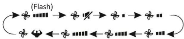
Change the operating fan speed.
Press FAN button to set the running fan speed, it can be set to AUTO/ MUTE/ LOW/ LOW-MID / MID/ MID-HIGH/ HIGH/ TURBO speed circularly.
flowchart
graph TD
    A["→"] --> B["→"]
    B --> C["→"]
    C --> D["→"]
    D --> E["→"]
    E --> F["→"]
    F --> G["→"]
    G --> H["→"]
    H --> I["→"]
    I --> J["→"]
    J --> K["→"]
    K --> L["→"]
    L --> M["→"]
    M --> N["→"]
    N --> O["→"]
    O --> P["→"]
    P --> Q["→"]
    Q --> R["→"]
    R --> S["→"]
    S --> T["→"]
    T --> U["→"]
    U --> V["→"]
    V --> W["→"]
    W --> X["→"]
    X --> Y["→"]
    Y --> Z["→"]
Child-Lock function
- Long press MODE and TIMER button together to active this function, and do it again to deactivate this function.
- Under this function, no single button will active.
TIMER function ---- TIMER ON SWING function
To automatic switch on the appliance.
When the unit is switch-off, you can set the TIMER ON.
To set the time of automatic switch-on as below:
- Press TIMER button first time to set the switch-on, ⏻ and [☐☐h] will appear on the remote display and flashes.
- Press^ or ∨ to button to set desired Timer-on time. Each time you press the button, the time increases/decreases by half an hour between 0 and 10 hours and by one between 10 and 24 hours.
- Press TIMER button second time to confirm.
- After Timer-on setting, set the needed mode (Cool/ Heat/ Auto/ Fan/ Dry), by press the MODE button. And set the needed fan speed, by press FAN button. And press^ or ∨ to set the needed operation temperature.
CANCEL it by press TIMER button.
TIMER function ---- TIMER OFF

To automatic switch off the appliance.
When the unit is switch-on, you can set the TIMER OFF.
To set the time of automatic switch-off, as below:
- Confirm the appliance is ON.
- Press the TIMER button at first time to set the switch-off.
Press ∧ or ∨ to set the needed timer. - Press TIMER button at the second time to confirm.
CANCEL it by press TIMER button.
Note: All programming should be operated within 5 seconds, otherwise the setting will be cancelled.
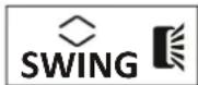
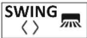
-
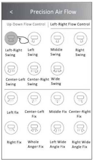
Press the button SWING to activate the louver,
1.1 Press SWING to activate the horizontal flaps to swing from up to down, the will appear on the remote display.
Press again to stop the swing movement at the current angle.
1.2 Press SWING <> to active the vertical deflectors to swing from left to right, the ☐ will appear on the remote display.
Press again to stop the swing movement at the current angle. -
If the vertical deflectors are positioned manually which placed under the flaps, they allow to move the air flow direct to rightward or leftward.
- For some inverter heating models, press horizontal SWING and vertical SWING together button at the same time, it will activate the Self-Clean function.
This adjustment must be done while the appliance is switched off.
⚠️ Never position Flaps manually, the delicate mechanism might seriously damaged!
⚠️ Never put fingers, sticks or other objects into the air inlet or outlet vents. Such accidental contact with live parts might cause unforeseeable damage or injury.
TURBO function
TURBO

To activate turbo function, press the TURBO button, and 🎨 will appear on the display.
Press again to cancel this function. In COOL/HEAT mode, when you select TURBO feature, the appliance will turn to quick COOL or quick HEAT mode, and operate the highest fan speed to blow strong airflow.
REMOTE CONTROL
MUTE function ECO function
MUTE
- Press MUTE button to active this function, and will appear on the remote display. Do it again to deactivate this function.
- When the MUTE function runs, the remote controller will display the auto fan speed, and the indoor unit will operate at lowest fan speed to be quiet feeling.
- When press FAN/ TURBO/ SLEEP button, the MUTE function will be cancel. MUTE function can not be activated under dry mode.
ECO

In this mode the appliance automatically sets the operation to save energy.
Press the ECO button, the ECO appears on the display, and the appliance will run in ECO mode. Press again to cancel it.
Note: The ECO function is available in both COOLING and HEATING modes.
SLEEP function
SLEEP

Pre-setting automatic operating program.
Press SLEEP button to activate the SLEEP function, and 🤕 appears on the display. Press again to cancel this function.
After 10 hours running in sleep mode, the air conditioner will change to the previous setting mode.
DISPLAY function (Indoor display)
DISPLAY
Switch ON/OFF the LED display on panel.
Press DISPLAY button to switch off the LED display on the panel. Press again to switch on the LED display.
I SET function (Optional)
Remember your favorite setting and run into it by press One button
Remember the favorite setting:
-
In each mode (COOLING/HEATING/FAN/DRY), long press "I SET" button over 3 seconds to remember it;
-
When "AU" flashing appears on the remote controller display, that means the remote controller remember your favorite setting;
* Press any button to quit, and you can reset it by repeat 1, 2 operation.
Run into the favorite setting:
-
In each mode (COOLING/HEATING/FAN/DRY), one press "I SET" button to active;
-
The appliance will run as your favorite setting and you will see [AU] flashing on the remote controller;
-
Press it again or other buttons to cancel this function.
OPERATION INSTRUCTIONS
Attempt to use the air conditioner under the temperature beyond the specified range may cause the air conditioner protection device to start and the air conditioner may fail to operate. Therefore, try to use the air conditioner in the following temperature conditions.
Inverter air conditioner:
| Temperature\MODE | Heating | Cooling | Dry |
| Room temperature | 0°C30 °C | 17°C2~°C | |
| Outdoor temperature | -20°C30 °C | -15°C53 °C | |
With the power supply connected, restart the air conditioner after shutdown, or switch it to other mode during operation, and the air conditioner protection device will start. The compressor will resume operation after 3 minutes.
Characteristics of heating operation (applicable to Heating pump)
Preheating:
When the heating function is enabled, the indoor unit will take 2\~5 minutes for preheating, after that the air conditioner will start heating and blows warm air.
Defrosting:
During heating, when the outdoor unit frosted, the air conditioner will enable the automatic defrosting function to improve the heating effect. During defrosting, the indoor and outdoor fans stop running. The air conditioner will resume heating automatically after defrosting finish.
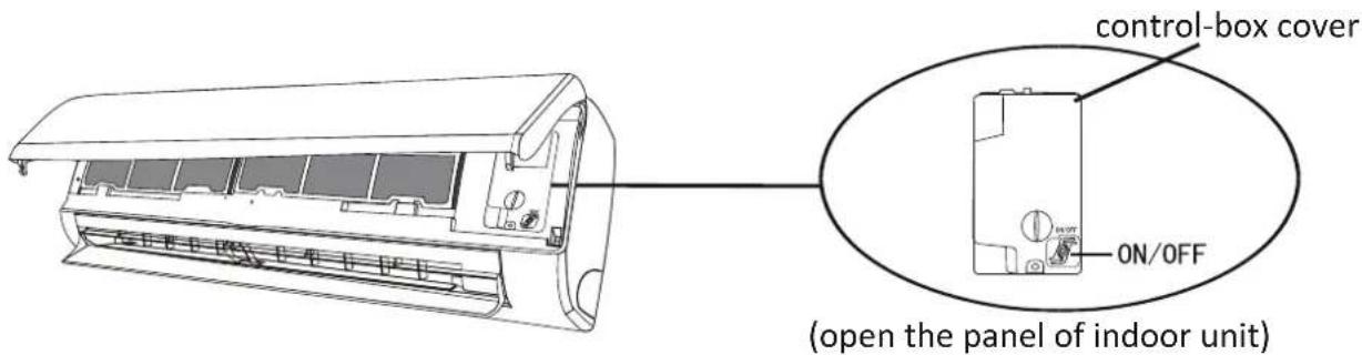
Emergency button:
Open the panel and find the emergency button on the electronic control box when the remote controller fails. (Always press the emergency button with insulation material.)
| Current status | Operation | Respond | Enter mode |
| Standby | Press the emergency button once | It beeps briefly once. | Cooling mode |
| Standby(Only for heating pump) | Press the emergency button twice in 3 seconds | It beeps briefly twice. | Heating mode |
| Running | Press the emergency button once | It keeps beeping for a while | Off mode |
INSTRUCTION FOR SERVICING(R32)
- Check the information in this manual to find out the dimensions of space needed for proper installation of the device, including the minimum distances allowed compared to adjacent structures.
- Appliance shall be installed, operated and stored in a room with a floor area larger than 4m^2 .
- The installation of pipe-work shall be kept to a minimum.
- The pipe-work shall be protected from physical damage, and shall not be installed in an unventilated space if the space is smaller than 4m^2 .
- The compliance with national gas regulations shall be observed.
- The mechanical connections shall be accessible for maintenance purposes.
- Follow the instructions given in this manual for handling, installing, cleaning, maintaining and disposing of the refrigerant.
- Make sure ventilation openings clear of obstruction.
- Notice: The servicing shall be performed only as recommended by the manufacturer.
- Warning: The appliance shall be stored in a well-ventilated area where the room size corresponds to the room area as specified for operation.
- Warning: The appliance shall be stored in a room without continuously operating open flames (for example an operating gas appliance) and ignition sources (for example an operating electric heater).
- The appliance shall be stored so as to prevent mechanical damage from occurring.
- It is appropriate that anyone who is called upon to work on a refrigerant circuit should hold a valid and up-to-date certificate from an assessment authority accredited by the industry and recognizing their competence to handle refrigerants, in accordance with the assessment specification recognized in the industrial sector concerned. Service operations should only be carried out in accordance with the recommendations of the equipment manufacturer. Maintenance and repair operations that require the assistance of other qualified persons must be conducted under the supervision of the person competent for the use of flammable refrigerants.
- Every working procedure that affects safety means shall only be carried out by competent persons.
- Warning:
* Do not use means to accelerate the defrosting process or to clean, other than those recommended by the manufacturer.
* The appliance shall be stored in a room without continuously operating ignition sources (for example: open flames, an operating gas appliance or an operating electric heater.
* Do not pierce or burn.
* Be aware that refrigerants may not contain an odor.
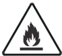
Caution: Risk of fire

natural_image
Simple line icon of an open book with a lowercase 'i' in the center, no text or symbols present.Operating instructions

natural_image
Illustration of an open book with a wrench resting on it (no text or symbols)Read technical manual
INSTRUCTION FOR SERVICING(R32)
16. Information on servicing:
1) Checks to the area
Prior to beginning work on systems containing flammable refrigerants, safety checks are necessary to ensure that the risk of ignition is minimized. For repair to the refrigerating system, the following precautions shall be complied with prior to conducting work on the system.
2) Work procedure
Work shall be undertaken under a controlled procedure so as to minimize the risk of a flammable gas or vapor being present while the work is being performed.
3) General work area
All maintenance staff and others working in the local area shall be instructed on the nature of work being carried out. Work in confined spaces shall be avoided. The area around the workspace shall be sectioned off. Ensure that the conditions within the area have been made safe by control of flammable material
4) Checking for presence of refrigerant
The area shall be checked with an appropriate refrigerant detector prior to and during work, to ensure the technician is aware of potentially flammable atmospheres. Ensure that the leak detection equipment being used is suitable for use with flammable refrigerants, i.e. non-sparking, adequately sealed or intrinsically safe.
5) Presence of fire extinguisher
If any hot work is to be conducted on the refrigeration equipment or any associated parts, appropriate fire extinguishing equipment shall be available to hand. Have a dry powder or CO_2 fire extinguisher adjacent to the charging area.
6) No ignition sources
No person carrying out work in relation to a refrigeration system which involves exposing any pipe work shall use any sources of ignition in such a manner that it may lead to the risk of fire or explosion. All possible ignition sources, including cigarette smoking, should be kept sufficiently far away from the site of installation, repairing, removing and disposal, during which refrigerant can possibly be released to the surrounding space. Prior to work taking place, the area around the equipment is to be surveyed to make sure that there are no flammable hazards or ignition risks. No Smoking signs shall be displayed.
7) Ventilated area
Ensure that the area is in the open or that it is adequately ventilated before breaking into the system or conducting any hot work. A degree of ventilation shall continue during the period that the work is carried out.
The ventilation should safely disperse any released refrigerant and preferably expel it externally into the atmosphere.
8) Checks to the refrigeration equipment
Where electrical components are being changed, they shall be fit for the purpose and to the correct specification. At all times the manufacturer's maintenance and service guidelines shall be followed.
If in doubt consult the manufacturer's technical department for assistance.
INSTRUCTION FOR SERVICING(R32)
The following checks shall be applied to installations using flammable refrigerants:
-- The charge size is in accordance with the room size within which the refrigerant containing parts are installed;
-- The ventilation machinery and outlets are operating adequately and are not obstructed;
-- If an indirect refrigerating circuit is being used, the secondary circuit shall be checked for the presence of refrigerant;
-- Marking to the equipment continues to be visible and legible. Markings and signs that are illegible shall be corrected;
-- Refrigeration pipe or components are installed in a position where they are unlikely to be exposed to any substance which may corrode refrigerant containing components, unless the components are constructed of materials which are inherently resistant to being corroded or are suitably protected against being so corroded.
9) Checks to electrical devices
Repair and maintenance to electrical components shall include initial safety checks and component inspection procedures. If a fault exists that could compromise safety, then no electrical supply shall be connected to the circuit until it is satisfactorily dealt with. If the fault cannot be corrected immediately but it is necessary to continue operation, an adequate temporary solution shall be used. This shall be reported to the owner of the equipment so all parties are advised.
Initial safety checks shall include:
-- That capacitors are discharged: this shall be done in a safe manner to avoid possibility of sparking;
-- That there no live electrical components and wiring are exposed while charging, recovering or purging the system;
-- That there is continuity of earth bonding.
17. Repairs to sealed components
1) During repairs to sealed components, all electrical supplies shall be disconnected from the equipment being worked upon prior to any removal of sealed covers, etc. If it is absolutely necessary to have an electrical supply to equipment during servicing, then a permanently operating form of leak detection shall be located at the most critical point to warn of a potentially hazardous situation.
2) Particular attention shall be paid to the following to ensure that by working on electrical components, the casing is not altered in such a way that the level of protection is affected. This shall include damage to cables, excessive number of connections, terminals not made to original specification, damage to seals, incorrect fitting of glands, etc. Ensure that apparatus is mounted securely. Ensure that seals or sealing materials have not degraded such that they no longer serve the purpose of preventing the ingress of flammable atmospheres. Replacement parts shall be in accordance with the manufacturer's specifications.
NOTE: The use of silicon sealant may inhibit the effectiveness of some types of leak detection equipment. Intrinsically safe components do not have to be isolated prior to working on them.
18. Repair to intrinsically safe components
Do not apply any permanent inductive or capacitance loads to the circuit without ensuring that this will not exceed the permissible voltage and current permitted for the equipment in use. Intrinsically safe components are the only types that can be worked on while live in the presence of a flammable atmosphere. The test apparatus shall be at the correct rating. Replace components only with parts specified by the manufacturer. Other parts may result in the ignition of refrigerant in the atmosphere from a leak.
INSTRUCTION FOR SERVICING(R32)
19. Cabling
Check that cabling will not be subject to wear, corrosion, excessive pressure, vibration, sharp edges or any other adverse environmental effects. The check shall also take into account the effects of aging or continual vibration from sources such as compressors or fans.
20. Detection of flammable refrigerants
Under no circumstances shall potential sources of ignition be used in the searching for or detection of refrigerant leaks. A halide torch (or any other detector using a naked flame) shall not be used.
21. Leak detection methods
The following leak detection methods are deemed acceptable for systems containing flammable refrigerants.
Electronic leak detectors shall be used to detect flammable refrigerants, but the sensitivity may not be adequate, or may need re-calibration. (Detection equipment shall be calibrated in a refrigerant-free area.) Ensure that the detector is not a potential source of ignition and is suitable for the refrigerant used. Leak detection equipment shall be set at a percentage of the LFL of the refrigerant and shall be calibrated to the refrigerant employed and the appropriate percentage of gas (25 % maximum) is confirmed. Leak detection fluids are suitable for use with most refrigerants but the use of detergents containing chlorine shall be avoided as the chlorine may react with the refrigerant and corrode the copper pipe-work. If a leak is suspected, all naked flames shall be removed/ extinguished. If a leakage of refrigerant is found which requires brazing, all of the refrigerant shall be recovered from the system, or isolated (by means of shut off valves) in a part of the system remote from the leak. Oxygen free nitrogen (OFN) shall then be purged through the system both before and during the brazing process.
22. Removal and evacuation
When breaking into the refrigerant circuit to make repairs or for any other purpose conventional procedures shall be used. However, it is important that best practice is followed since inflammability is a consideration. The following procedure shall be adhered to:
-- Remove refrigerant;
-- Purge the circuit with inert gas;
-- Evacuate;
-- Purge again with inert gas;
-- Open the circuit by cutting or brazing.
The refrigerant charge shall be recovered into the correct recovery cylinders. The system shall be flushed with OFN to render the unit safe. This process may need to be repeated several times.
Compressed air or oxygen shall not be used for this task.
Flushing shall be achieved by breaking the vacuum in the system with OFN and continuing to fill until the working pressure is achieved, then venting to atmosphere, and finally pulling down to a vacuum. This process shall be repeated until no refrigerant is within the system. When the final OFN charge is used, the system shall be vented down to atmospheric pressure to enable work to take place. This operation is absolutely vital if brazing operations on the pipe-work are to take place.
Ensure that the outlet for the vacuum pump is not close to any ignition sources and there is ventilation available.
23. Decommissioning
Before carrying out this procedure, it is essential that the technician is completely familiar with the equipment and all its detail. It is recommended good practice that all refrigerants are recovered safely. Prior to the task being carried out, an oil and refrigerant sample shall be taken in case analysis is required prior to re-use of reclaimed refrigerant. It is essential that electrical power is available before the task is commenced.
INSTRUCTION FOR SERVICING(R32)
a) Become familiar with the equipment and its operation.
b) Isolate system electrically.
c) Before attempting the procedure, ensure that:
. mechanical handling equipment is available, if required, for handling refrigerant cylinders;
. all personal protective equipment is available and being used correctly;
. the recovery process is supervised at all times by a competent person;
. recovery equipment and cylinders conform to the appropriate standards.
d) Pump down refrigerant system, if possible.
e) If a vacuum is not possible, make a manifold so that refrigerant can be removed from various parts of the system.
F) Make sure that cylinder is situated on the scales before recovery takes place.
g) Start the recovery machine and operate in accordance with manufacturer's instructions.
h) Do not overfill cylinders. (No more than 80 % volume liquid charge).
i) Do not exceed the maximum working pressure of the cylinder, even temporarily.
J) When the cylinders have been filled correctly and the process completed, make sure that the cylinders and the equipment are removed from site promptly and all isolation valves on the equipment are closed off.
K) Recovered refrigerant shall not be charged into another refrigeration system unless it has been cleaned and checked.
24. Labeling
Equipment shall be labeled stating that it has been de-commissioned and emptied of refrigerant. The label shall be dated and signed. Ensure that there are labels on the equipment stating the equipment contains flammable refrigerant.
25. Recovery
When removing refrigerant from a system, either for servicing or decommissioning, it is recommended good practice that all refrigerants are removed safely.
When transferring refrigerant into cylinders, ensure that only appropriate refrigerant recovery cylinders are employed. Ensure that the correct number of cylinders for holding the total system charge are available. All cylinders to be used are designated for the recovered refrigerant and labeled for that refrigerant (i.e. Special cylinders for the recovery of refrigerant). Cylinders shall be complete with pressure-relief valve and associated shut-off valves in good working order. Empty recovery cylinders are evacuated and, if possible, cooled before recovery occurs.
The recovery equipment shall be in good working order with a set of instructions concerning the equipment that is at hand and shall be suitable for the recovery of all appropriate refrigerants including, when applicable, flammable refrigerants. In addition, a set of calibrated weighing scales shall be available and in good working order. Hoses shall be complete with leak-free disconnect couplings and in good condition. Before using the recovery machine, check that it is in satisfactory working order, has been properly maintained and that any associated electrical components are sealed to prevent ignition in the event of a refrigerant release. Consult manufacturer if in doubt. The recovered refrigerant shall be returned to the refrigerant supplier in the correct recover cylinder, and the relevant waste transfer note arranged. Do not mix refrigerants in recovery units and especially not in cylinders.
If compressors or compressor oils are to be removed, ensure that they have been evacuated to an acceptable level to make certain that flammable refrigerant does not remain within the lubricant. The evacuation process shall be carried out prior to returning the compressor to the suppliers.
Only electric heating to the compressor body shall be employed to accelerate this process. When oil is drained from a system, it shall be carried out safely.
INSTALLATION PRECAUTIONS(R32)
Important Considerations
- The air conditioner must be installed by professional personnel and the Installation manual is used only for the professional installation personnel! The installation specifications should be subject to our after-sale service regulations.
- When filling the combustible refrigerant, any of your rude operations may cause serious injury or injuries to human body and objects.
- A leak test must be done after the installation completed.
- It is a must to do the safety inspection before maintaining or repairing an air conditioner using combustible refrigerant in order to ensure that the fire risk is reduced to minimum.
- It is necessary to operate the machine under a controlled procedure in order to ensure that any risk arising from the combustible gas or vapor during the operation is reduced to minimum.
- Requirements for the total weight of filled refrigerant and the area of a room to be equipped with an air conditioner (are shown as in the following Tables GG.1 and GG.2)
The maximum charge and the required minimum floor area
$$ m _ {1} = \left(4 m ^ {3}\right) \times L F L, m _ {2} = \left(2 6 m ^ {3}\right)) \times L F L, m _ {3} = \left(1 3 0 m ^ {3}\right) \times L F L $$
Where LFL is the lower flammable limit in kg/ m^3 , R32 LFL is 0.306 kg/ m^3 .
For the appliances with a charge amount m_1 < M = m_2 :
The maximum charge in a room shall be in accordance with the following:
$$ m _ {\max \overline {{0}}} = 2. 5 \times (L F L) ^ {(5 / 4)} \times h \times (A) $$
The required minimum floor area Amin to install an appliance with refrigerant charge M (kg) shall be in accordance with following: A_ = (M/(2.5 × (LFL)^(5/4) × h))^2
Where:
Table GG.1 - Maximum charge (kg)
| Category | LFL (kg/m3) | h_0(m) | Floor area (m2) | ||||||
| 4 | 7 | 10 | 15 | 20 | 30 | 50 | |||
| R32 | 0.306 | 1 | 1.14 | 1.51 | 1.8 | 2.2 | 2.54 | 3.12 | 4.02 |
| 1.8 | 2.05 | 2.71 | 3.24 | 3.97 | 4.58 | 5.61 | 7.254 | ||
| 2.2 | 2.5 | 3.31 | 3.96 | 4.85 | 5.6 | 6.86 | 8.85 | ||
Table GG.2 - Minimum room area (m²)
| Category | LFL (kg/m3) | h_0(m) | Charge amount (M) (kg)Minimum room area (m3) | ||||||
| R32 | 0.306 | 1.224kg | 1.836kg | 2.448kg | 3.672kg | 4.896kg | 6.12kg | 7.956kg | |
| 0.6 | 29 | 51 | 116 | 206 | 321 | 543 | |||
| 1 | 10 | 19 | 42 | 74 | 116 | 196 | |||
| 1.8 | 3 | 6 | 13 | 23 | 36 | 60 | |||
| 2.2 | 2 | 4 | 9 | 15 | 24 | 40 | |||
Installation Safety Principles
1. Site Safety
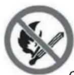
Open Flames Prohibited
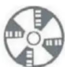
Ventilation Necessary
2. Operation Safety
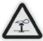
Mind Static Electricity

Must wear protective clothing and anti-static gloves

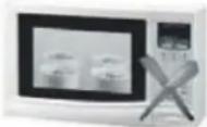
Don't use mobile phone
INSTALLATION PRECAUTIONS(R32)
3. Installation Safety
• Refrigerant Leak Detector
• Appropriate Installation Location
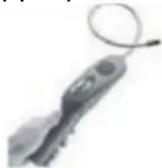
The left picture is the schematic diagram of a refrigerant leak detector.
Please note that:
- The installation site should be well-ventilated.
- The sites for installing and maintaining an air conditioner using Refrigerant R32 should be free from open fire or welding, smoking, drying oven or any other heat source higher than 548 which easily produces open fire.
- When installing an air conditioner, it is necessary to take appropriate anti-static measures such as wear anti-static clothing and/or gloves.
- It is necessary to choose the site convenient for installation or maintenance wherein the air inlets and outlets of the indoor and outdoor units should be not surrounded by obstacles or close to any heat source or combustible and/or explosive environment.
- If the indoor unit suffers refrigerant leak during the installation, it is necessary to immediately turn off the valve of the outdoor unit and all the personnel should go out till the refrigerant leaks completely for 15 minutes. If the product is damaged, it is a must to carry such damaged product back to the maintenance station and it is prohibited to weld the refrigerant pipe or conduct other operations on the user's site.
- It is necessary to choose the place where the inlet and outlet air of the indoor unit is even.
- It is necessary to avoid the places where there are other electrical products, power switch plugs and sockets, kitchen cabinet, bed, sofa and other valuables right under the lines on two sides of the indoor unit.
Suggested Tools
| Tool | Picture | Tool | Picture | Tool | Picture |
| Standard Wrench | 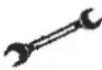 | Pipe Cutter |  | Vacuum Pump |  |
| Adjustable/Crescent Wrench | 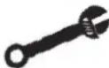 | Screw drivers(Phillips & Flat blade) | 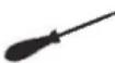 | Safety Glasses |  |
| Torque Wrench | 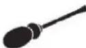 | Manifold andGauges | 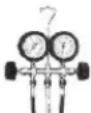 | Work Gloves |  |
| Hex Keys orAllen Wrenches |  | Level | 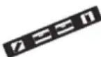 | Refrigerant Scale |  |
| Drill & Drill Bits |  | Flaring tool |  | Micron Gauge |  |
| Hole Saw |  | Clamp on AmpMeter | 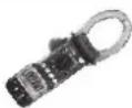 |
INSTALLATION PRECAUTIONS
Pipe Length and Additional Refrigerant
| Inverter Models Capacity (Btu/h) | 9K-12K 18K-24K | |
| Lenght of pipe with standard charge | 5m 5m | |
| Maximum distance between indoor and outdoor unit | 25m | 25m |
| Additional refrigerant charge | 15g/m | 25g/m |
| Max. diff. in level between indoor and outdoor unit | 10m | 10m |
| Type of refrigerant | R32 | R32 |
Torque Parameters
| PIPE Size | Newton meter[N x m] | Pound-force foot (1bf-ft) | Kilogram-force meter (kgf-m) |
| 1/4 " (Φ 6.35) | 15 - 20 | 11.1 - 14.8 | 1.5 - 2.0 |
| 3/8 " (Φ 9.52) | 31 - 35 | 22.9 - 25.8 | 3.2 - 3.6 |
| 1/2 " (Φ 12) | 45 - 50 | 33.2 - 36.9 | 4.6 - 5.1 |
| 5/8 " (Φ 15.88) | 60 - 65 | 44.3 - 48.0 | 6.1 - 6.6 |
Dedicated Distribution Device and Wire for Air Conditioner
| INVERTER TYPEMODEL capacity (Btu/h) | 9k | 12k | 18k | 24k | |
| sectional area | |||||
| Power supply cable | N | 1.5mm^2 | 1.5mm^2 | 1.5mm^2 | 2.5mm^2 |
| L | 1.5mm^2 | 1.5mm^2 | 1.5mm^2 | 2.5mm^2 | |
| 1.5mm^2 | 1.5mm^2 | 1.5mm^2 | 2.5mm^2 | ||
| Connection cable | N | 0.75mm^2 | 0.75mm^2 | 0.75mm^2 | 0.75mm^2 |
| L or (L) | 0.75mm^2 | 0.75mm^2 | 0.75mm^2 | 0.75mm^2 | |
| 1 | 0.75mm^2 | 0.75mm^2 | 0.75mm^2 | 0.75mm^2 | |
| 0.75mm^2 | 0.75mm^2 | 0.75mm^2 | 0.75mm^2 | ||

Note: This table is only for reference, the installation shall meet the requirements of local laws and regulations.
INDOOR UNIT INSTALLATION
Step1: Select Installation location
1.1 Ensure the installation complies with the installation minimum dimensions (defined below) and meets the minimum and maximum connecting piping length and maximum change in elevation as defined in the System Requirements section.
1.2 Air inlet and outlet will be clear of obstructions, ensuring proper airflow throughout the room.
1.3 Condensate can be easily and safely drained.
1.4 All connections can be easily made to outdoor unit.
1.5 Indoor unit is out of reach of children.
1.6 A mounting wall strong enough to withstand four times the full weight and vibration of the unit.
1.7 Filter can be easily accessed for cleaning.
1.8 Leave enough free space to allow access for routine maintenance.
1.9 Install at least 10 ft. (3 m) away from the antenna of TV set or radio. Operation of the air conditioner may interfere with radio or TV reception in areas where reception is weak. An amplifier may be required for the affected device.
1.10 Do not install in a laundry room or by a swimming pool due to the corrosive environment.
Minimum Indoor Clearances
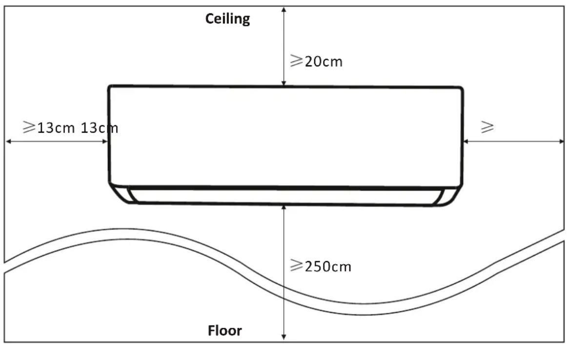
INDOOR UNIT INSTALLATION
Step2: Install Mounting Plate
2.1 Take the mounting plate from the back of indoor unit.
2.2 Ensure to meet the minimum installation dimension requirements as step 1, according to the size of mounting plate, determine the position and stick the mounting plate close to the wall.
2.3 Adjust the mounting plate to a horizontal state with a spirit level, then mark out the screw hole positions on the wall.
2.4 Put down the mounting plate and drill holes in the marked positions with drill.
2.5 Insert expansion rubber plugs into the holes, then hang the mounting plate and fix it with screws.
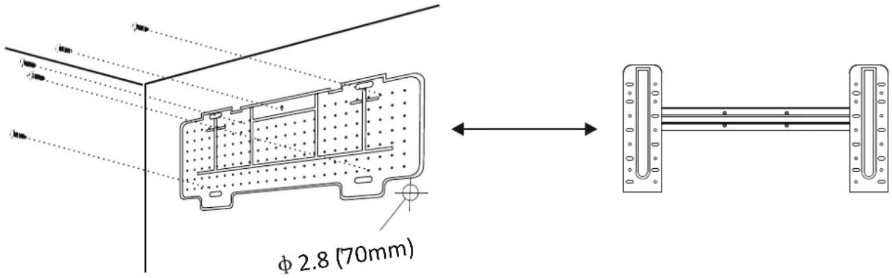
Note:
(I) Make sure the mounting plate is firm enough and flat against the wall after installation.
(II) This figure shown may be different from the actual object, please take the latter as the standard.
Step3: Drill Wall Hole
A hole in the wall should be drilled for refrigerant piping, the drainage pipe, and connecting cables.
3.1 Determine the location of wall hole base on the position of mounting plate.
3.2 The hole should be have a 70mm diameter at least and a small oblique angle to facilitate drainage.
3.3 Drill the wall hole with 70mm core drill and with small oblique angle lower than the indoor end about 5mm to 10mm.
3.4 Place the wall sleeve and wall sleeve cover(both are optional parts) to protect the connection parts.
Caution:
When drill the wall hole, maker sure to avoid wires, plumbing and other sensitive components.
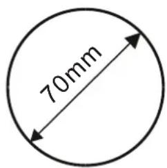
Wall sleeve Cover (Optional)
Indoor

INDOOR UNIT INSTALLATION
Step4: Connecting Refrigerant Pipe
4.1 According to the wall hole position, select the appropriate piping mode.
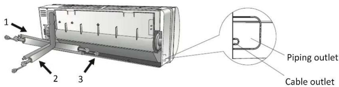
There are three optional piping modes for indoor units as shown in the figure below: In Piping Mode 1 or Piping Mode 3, a notch should be made by using scissors to cut the plastic sheet of piping outlet and cable outlet on the corresponding side of the indoor unit.
Note: When cutting off the plastic sheet at the outlet, the cut should be trimmed to smooth.
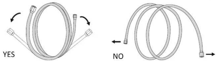
4.2 Bending the connecting pipes with the port facing up as shown in the figure.
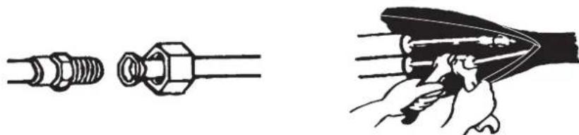
4.3 Take off the plastic cover in the pipe ports and take off the protective cover on the end of piping connectors.
4.4 Check whether there is any sundry on the port of the connecting pipe and make ensure the port is clean.
4.5 After align the center, rotate the nut of the connecting pipe to tighten the nut as tightly as possible by hand.
4.6 Use a torque wrench to tighten it according to the torque values in the torque requirements table; (Refer to the torque requirements table on section INSTALLATION PRECAUTIONS)
4.7 Wrap the joint with the insulation pipe.
natural_image
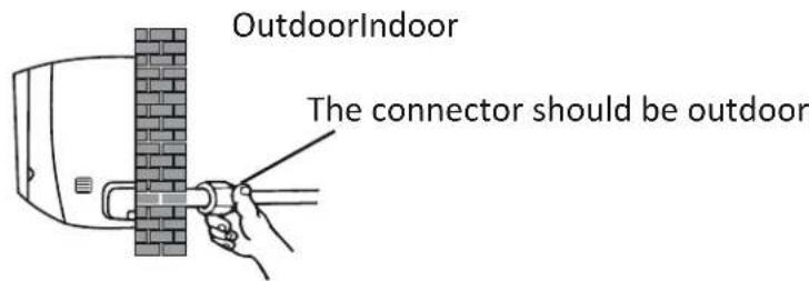
Illustration of two mechanical components: a threaded bolt and a hexagonal nut, with a hand holding a tool inside (no text or symbols)Note: For R32 refrigerant, the connector should be placed outdoors.
INDOOR UNIT INSTALLATION
Step5: Connect Drainage Hose
5.1 Adjust the drainage hose(if applicable)
In some model, both sides of the indoor unit are provided with drainage ports, you can choose one of them to attach the drainage hose. And plug the unused drain port with the rubber attached in one of the ports.
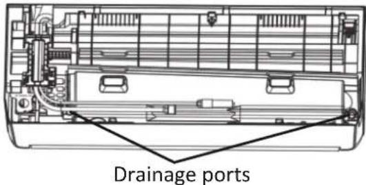
5.2 Connect the drainage hose to the drainage port, ensure the joint is firm and the sealing effect is good.
5.3 Wrap the joint firmly with teflon tape to ensure no leaks.
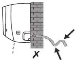
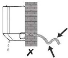
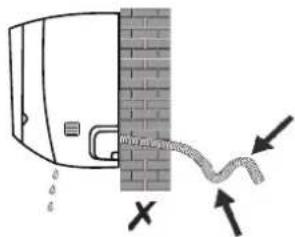
Note: Make sure there is no twists or dents, and the pipes should be placed obliquely downward to avoid blockage, to ensure proper drainage.
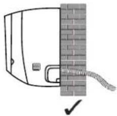
natural_image
Simple line drawing of a door with a brick wall and a rope attached to the door (no text or symbols)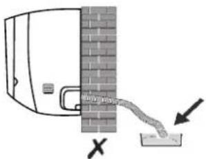
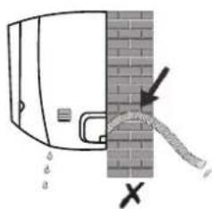
Step6: Connect Wiring
6.1 Choose the right cables size determined by the maximum operating current on the nameplate. (Check the cables size refer to section INSTALLATION PRECAUTIONS)
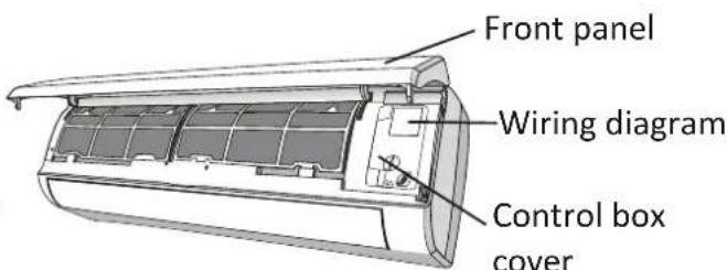
6.2 Open the front panel of indoor unit.
6.3 Use a screwdriver, open the electric control box cover, to reveal the terminal block.
6.4 Unscrew the cable clamp.
6.5 Insert one end of the cable into the position of control box from the back of the right end of the indoor unit.
6.6 Connect the wires to corresponding terminal according to the wiring diagram on the electric control box cover. And make sure that they are well connected.
6.7 Screw the cable clamp to fasten the cables.
6.8 Reinstall the electric control box cover and front panel.
INDOOR UNIT INSTALLATION
Step7: Wrap Piping and Cable
After the refrigerant pipes, connecting wires and drainage hose are all installed, in order to save space, protect and insulate them, it must be bundle with insulating tape before passing them through the wall hole.
7.1 Arrange the pipes, cables and drainage hose well as the following picture.
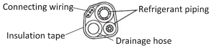
Note: (Make sure the drainage hose is at the bottom.
(A) void crossing and bending of parts.
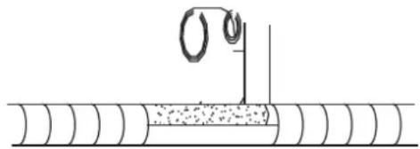
7.2 Using the insulating tape wrap the refrigerant pipes, connecting wires and drainage hose together tightly.
natural_image
Diagram of a pipe installation with a coiled wire and granular material (no text or symbols)Step8: Mount Indoor Unit
8.1 Slowly pass the refrigerant pipes, connecting wires and drainage hose wrapped bundle through the wall hole.
8.2 Hook the top of indoor unit on the mounting plate.
8.3 Apply slight pressure to the left and right sides of the indoor unit, make sure the indoor unit is hooked firmly.
8.4 Push down the bottom of indoor unit to let the snaps onto the hooks of the mounting plate, and make sure it is hooked firmly.
Sometimes, if the refrigerant pips were already embedded in the wall, or if you want to connecting the pips and wires on the wall, do as below:
(I) Hook the top of the indoor unit on the mounting plate without piping and wiring.
(II) Lift the indoor unit opposite the wall, unfold the bracket on the mounting plate, and use this bracket to prop up the indoor unit, there will be a big space for operation.
(III) Do the refrigerant piping, wiring, connect drainage hose, and wrap them as Step 4 to 7.
OUTDOOR UNIT INSTALLATION
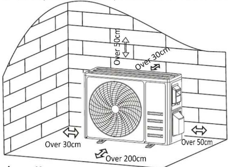
Step1: Select Installation Location
Select a site that allows for the following:
1.1 Do not install the outdoor unit near sources of heat, steam or flammable gas.
1.2 Do not install the unit in too windy or dusty places.
1.3 Do not install the unit where people often pass. Select a place where the air discharge and operating sound will not disturb the neighbors.
1.4 Avoid installing the unit where it will be exposed to direct sunlight (other wise use a protection, if necessary, that should not interfere with the air flow).
1.5 Reserve the spaces as shown in the picture for the air to circulate freely.
1.6 Install the outdoor unit in a safe and solid place.
1.7 If the outdoor unit is subject to vibration, place rubber blankets onto the feet of the unit.
Step2: Install Drainage Hose
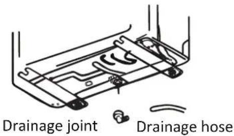
2.1 This step only for heating pump models.
2.2 Insert the drainage joint to the hole at the bottom of the outdoor unit.
2.3 Connect the drainage hose to the joint and make the connection well enough.
Step3: Fix Outdoor Unit
3.1 According to the outdoor unit installation dimensions to mark the installation position for expansion bolts.
3.2 Drill holes and clean the concrete dust and place the bolts.
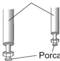
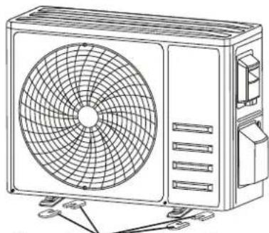
3.3 If applicable install 4 rubber blankets on the hole before place the outdoor unit (Optional). This will reduce vibrations and noise.
3.4 Place the outdoor unit base on the bolts and pre-drilled holes.
3.5 Use wrench to fix the outdoor unit firmly with bolts.
Note:
The outdoor unit can be fixed on a wall-mounting bracket. Follow the instruction of the wall-mounting bracket to fix the wall-mounted bracket fasten the outdoor unit on it and keep it horizontal.
The wall-mounting bracket must be able to support at least 4 times of the weight of outdoor unit.
natural_image
Line drawing of a dual-panel air conditioner unit with fan blades and ventilation slots (no text or symbols)Install 4 rubber blankets (Optional)
OUTDOOR UNIT INSTALLATION
Step4: Install Wiring
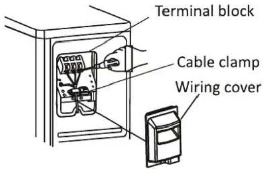
4.1 Use a phillips screwdriver to unscrew wiring cover, grasp and press it down gently to take it down.
4.2 Unscrew the cable clamp and take it down.
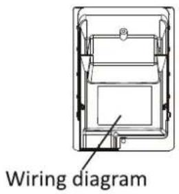
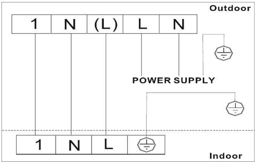
4.3 According to the wiring diagram pasted inside the wiring cover, connect the connecting wires to the corresponding terminals, and ensure all connections are firmly and securely.
4.4 Reinstall the cable clamp and wiring cover.
Note: When connecting the wires of indoor and outdoor units, the power should be cut off.
Step5: Connecting Refrigerant Pipe
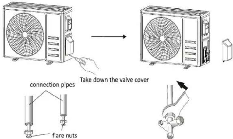
5.1 Unscrews the valve cover, grasp and press it down gently to take it down(if the valve cover is applicable).
5.2 Remove the protective caps from the end of valves.
5.3 Take off the plastic room in your indoor pipe port, point of the connecting pipe and make ensure the port is clean.
5.4 After align the center, rotate the flare nut of the connecting pipe to tighten the nut as tightly as possible by hand.
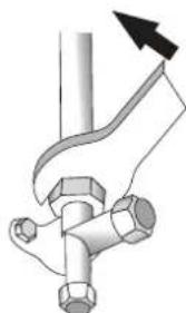
5.5 Use a spanner hold the body of the valve and use a torque wrench to tighten the flare nut according to the torque values in the torque requirements table.
(Refer to the torque requirements table on section INSTALLATION PRECAUTIONS)
OUTDOOR UNIT INSTALLATION
Step6: Vacuum Pumping
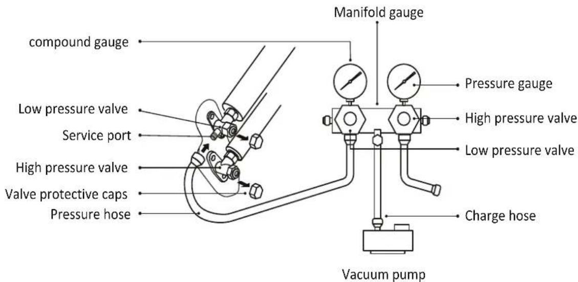
6.1 Use a spanner to take down the protective caps from the service port, low pressure valve and high pressure valve of the outdoor unit.
6.2 Connect the pressure hose of manifold gauge to the service port on the outdoor unit low pressure valve.
6.3 Connect the charge hose from the manifold gauge to the vacuum pump.
6.4 Open the low pressure valve of the manifold gauge and close the high pressure valve.
6.5 Turn on the vacuum pump to vacuum the system.
6.6 The vacuum time should not be less than 15 minutes, or make sure the compound gauge indicates -0.1 MPa (-76 cmHg)
6.7 Close the low pressure valve of the manifold gauge and turn off the vacuum.
6.8 Hold the pressure for 5 minutes, make sure that the rebound of compound gauge pointer does not exceed 0.005 MPa .
6.9 Open the low pressure valve counterclockwise for 1/4 turn with hexagonal wrench to let a little refrigerant fill in the system, and close the low pressure valve after 5 seconds and quickly remove the pressure hose.
6.10 Check all indoor and outdoor joints for leakage with soapy water or leak detector.
6.11 Fully open the low pressure valve and high pressure valve of the outdoor unit with hexagonal wrench.
6.12 Reinstall the protective caps of the service port, low pressure valve and high pressure valve of the outdoor unit.
6.13 Reinstall the valve cover.
TEST OPERATION
Inspections Before Test Run
Do the following checks before test run.
| Description | Inspection method |
| Electrical safety inspection | Check whether the power supply voltage complies with specification.Check whether there is any wrong or missing connection between the power lines, signal line and earth wires.Check whether the earth resistance and insulation resistance comply with requirements. |
| Installation safety inspection | Confirm the direction and smoothness of drainage pipe.Confirm that the joint of refrigerant pipe is installed completely.Confirm the safety of outdoor unit, mounting plate and indoor unit installation.Confirm that the valves are fully open.Confirm that there are no foreign objects or tools left inside the unit.Complete installation of indoor unit air inlet grille and panel. |
| Refrigerant leakage detection | The piping joint, the connector of the two valves of the outdoor unit, the valve spool, the welding port, etc., where leakage may occur.Foam detection method:Apply soapy water or foam evenly on the parts where leakage may occur, and observe whether bubbles appear or not, if not, it indicates that the leakage detection result is safe.Leak detector method:Use a professional leak detector and read the instruction of operation, detect at the position where leakage may occur.The duration of leak detection for each position should last for 3 minutes or more;If the test result shows that there is leakage, the nut should be tightened and tested again until there is no leakage;After the leak detection is completed, wrap the exposed pip connector of indoor unit with thermal insulation material and wrap with insulation tape. |
TEST OPERATION
Test Run Instruction
- Turn on the power supply.
-
Press the ON/OFF button on the remote controller to turn on the air conditioner.
-
Press the Mode button to switch the mode COOL and HEAT.
In each mode set as below: COOL-Set the lowest temperature HEAT-Set the highest temperature
- Run about 8 minutes in each mode and check all functions are properly run and respond the remote controller. Functions check as recommended:
4.1 If the outlet air temperature respond the cool and heat mode
4.2 If the water drains properly from the drainage hose
4.3 If the Louver and deflectors(optional) rotate properly
-
Observe the test run state of the air conditioner at least 30 minutes.
-
After the successfully test run, return the normal setting and press ON/OFF button on the remote controller to turn off the unit.
-
Inform the user to read this manual carefully before use, and demonstrate to the user how to use the air conditioner, the necessary knowledge for service and maintenance, and the reminder for storage of accessories.
Note:
If the ambient temperature is excess the range refer to section OPERATION INSTRUCTIONS, and it can not run COOL or HEAT mode, lift the front panel and refer to the emergency button operation to run the COOL and HEAT mode.
MAINTENANCE
| Warning | When cleaning, you must shut down the machine and cut off the power supply for more than 5 minutes.Under no circumstances should the air conditioner be flushed with water.Volatile liquid (e.g. thinner or gasoline) will damage the air conditioner, so only use soft dry cloth or wet cloth dipped with neutral detergent to clean the air conditioner.Pay attention to cleaning the filter screen regularly to avoid dust covering which will affect the filter screen effect. When the operating environment is dusty, the cleaning frequency should be increased appropriately.After removing the filter screen, do not touch the fins of the indoor unit to avoid scratching. | |
| Clean the unit | 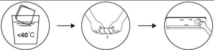 Wring it dry Gentle wipe the unit surfaceTip: Wipe frequently to keep air conditioner clean and good appearance . Wring it dry Gentle wipe the unit surfaceTip: Wipe frequently to keep air conditioner clean and good appearance . | |
| Clean the filter | 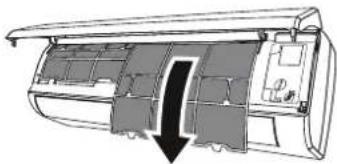 → → 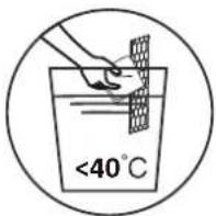 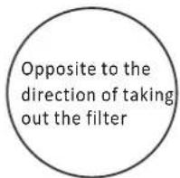 Take out the filter from the unit Clean the filter with soapy water and air dry it Replace the filterTip: When you find accumulated dust in the filter, please clean the filter in time to ensure the clean, healthy and efficient operation inside the air conditioner. Take out the filter from the unit Clean the filter with soapy water and air dry it Replace the filterTip: When you find accumulated dust in the filter, please clean the filter in time to ensure the clean, healthy and efficient operation inside the air conditioner. | |
| Service and maintenance | When the air conditioner is not in use for a long time, do the following work:Take out the batteries of the remote controller and disconnect the power supply of the air conditioner.When starting to use after long-term shutdown:Clean the unit and filter screen;Check whether there are obstacles at the air inlet and outlet of indoor and outdoor units;Check whether the drain pipe is unobstructed;Install the batteries of the remote controller and check whether the power is on. | |
TROUBLESHOOTING
| MALFUNCTION | POSSIBLE CAUSES |
| The appliance does not operate | Power failure/plug pulled out. |
| Damaged indoor/outdoor unit fan motor. | |
| Faulty compressor thermomagnetic circuit breaker. | |
| Faulty protective device or fuses. | |
| Loose connections or plug pulled out. | |
| It sometimes stops operating to protect the appliance. | |
| Voltage higher or lower than the voltage range. | |
| Active TIMER-ON function. | |
| Damaged electronic control board. | |
| Strange odor | Dirty air filter. |
| Noise of running water | Back flow of liquid in the refrigerant circulation. |
| A fine mist comes from the air outlet | This occurs when the air in the room becomes very cold, for example in the COOLING or DEHUMIDIFYING/DRY modës. |
| A strange noise can be heard | This noise is made by the expansion or contraction of the front panel due to variations in temperature and does not indicate a problem. |
| Insufficient airflow, either hot or cold | Unsuitable temperature setting. |
| Obstructed air conditioner intakes and outlets. | |
| Dirty air filter. | |
| Fan speed set at minimum. | |
| Other sources of heat in the room. | |
| No refrigerant. | |
| The appliance does not respond to commands | Remote control is not close enough to indoor unit. |
| The batteries of remote control need to be replaced. | |
| Obstacles between remote control and signal receiver in indoor unit. | |
| The display is off | Active DISPLAY function. |
| Power failure. | |
| Switch off the air conditioner immediately and cut off the power supply in the event of: | Strange noises during operation. |
| Faulty electronic control board. | |
| Faulty fuses or switches. | |
| Spraying water or objects inside the appliance. | |
| Overheated cables or plugs. | |
| Very strong smells coming from the appliance. |
TROUBLESHOOTING
ERROR CODE ON THE DISPLAY
In case of error, the display on the indoor unit shown the following error codes:
| Display | Description of the trouble |
| E1 | Indoor room temperature sensor fault |
| E2 | Indoor pipe temperature sensor fault |
| E3 | Outdoor pipe temperature sensor fault |
| E4 | Refrigerant system leakage or fault |
| E6 | Malfunction of indoor fan motor |
| E7 | Outdoor ambient temperature sensor fault |
| E0 | Indoor and outdoor communication fault |
| E8 | Outdoor discharge temperature sensor fault |
| E9 | Outdoor IPM module fault |
| EA | Outdoor current detect fault |
| EE | Outdoor PCB EEPROM fault |
| EF | Outdoor fan motor fault |
| EH | Outdoor suction temperature sensor fault |
DISPOSAL GUIDELINE (European)
This appliance contains refrigerant and other potentially hazardous materials. When disposing of this appliance, the law requires special collection and treatment. DO NOT dispose of this product as household waste or unsorted municipal waste.
When disposing of this appliance, you have the following options:
- Dispose of the appliance at designated municipal electronic waste collection facility.
- When buying a new appliance, the retailer will take back the old appliance free of charge.
- The manufacturer will also take back the old appliance free of charge.
- Sell the appliance to certifid scrap metal dealers.
- Disposing of this appliance in the forest or other natural surroundings endangers your health and is bad for the environment. Hazardous substances may leak into the ground water and enter the food chain.
Corberó
natural_image
Simple icon of a house with a curved roof and loop, no text or symbols present.SmartLife-SmartHome
flowchart
graph TD
    A["Scan the activation QR code from instructions or device"] --> B["Scan"]
    B --> C["or Enter Activation Code"]
    C --> D["or Enter Activation Code"]
    D --> E["*******"]
    E --> F["CANCEL CONFIRM"]

Inicio de sesión
Inicio de sesión
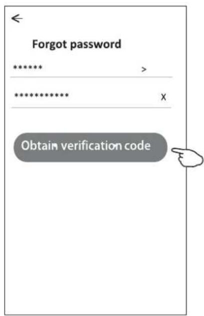
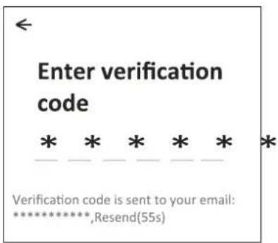
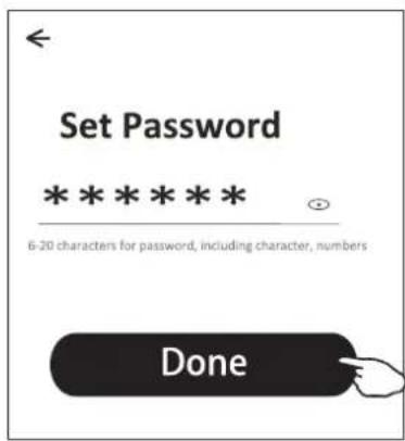
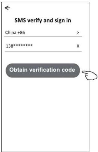
Contraseña olvidada
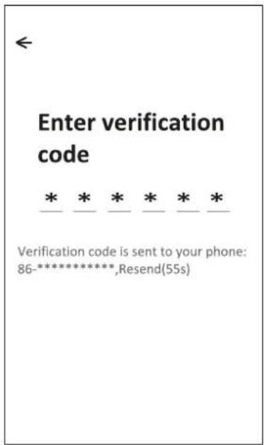
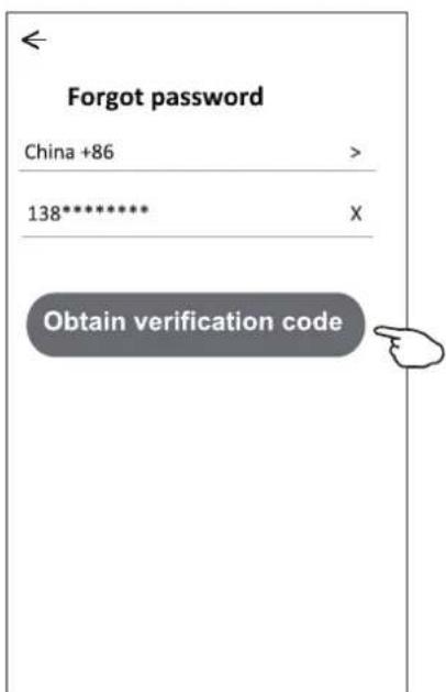
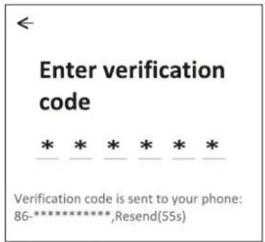
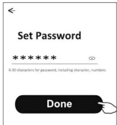
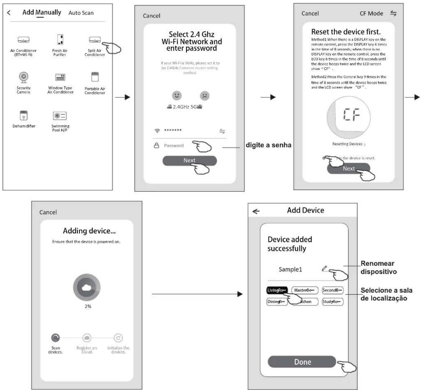
Add device (Agregar dispositivo)
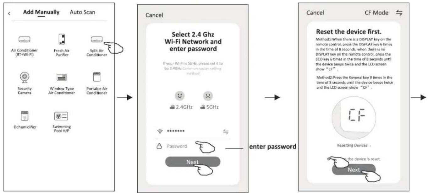
flowchart
graph LR
    A["Add Manually Auto Scan"] --> B["Cancel Select 2.4 Ghz Wi-Fi Network and enter password"]
    B --> C["Enter Password"]
    C --> D["Cancel CF Mode Reset the device first."]
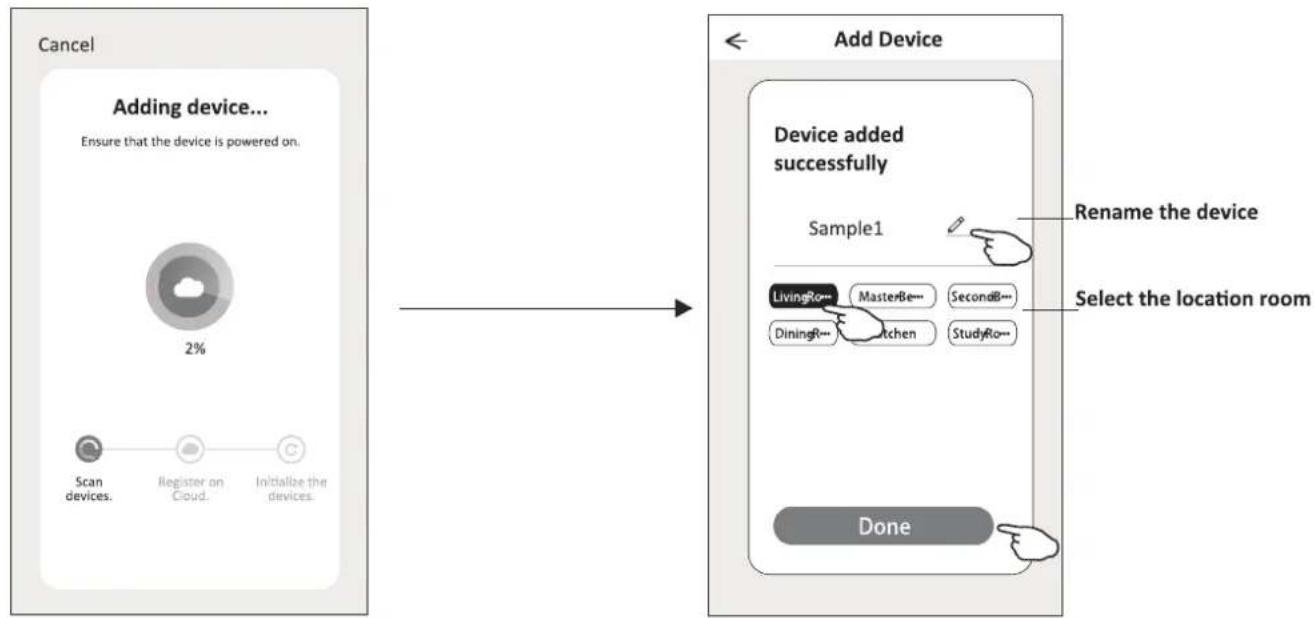
flowchart
graph LR
    A["Cancel"] --> B["Adding device..."]
    B --> C["Ensure that the device is powered on."]
    C --> D["Scan devices."]
    C --> E["Register on Cloud."]
    C --> F["Initialize the devices."]

    B --> G["Add Device"]
    G --> H["Device added successfully"]
    H --> I["Sample1"]
    I --> J["LivingRo--- MasterBe--- SecondB--- DiningR--- Kitchen StudyRo--- Done"]

    style A fill:#f9f,stroke:#333
    style G fill:#ccf,stroke:#333
Add device (Agregar dispositivo)
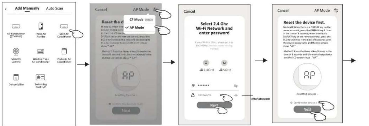
flowchart
graph LR
    A["Add Manually Auto Scan"] --> B["Cancel"]
    B --> C["AP Mode"]
    C --> D["Select 2.4 GHz Wi-Fi Network and enter password"]
    D --> E["Cancel"]
    E --> F["AP Mode"]
    F --> G["Reset the device first."]
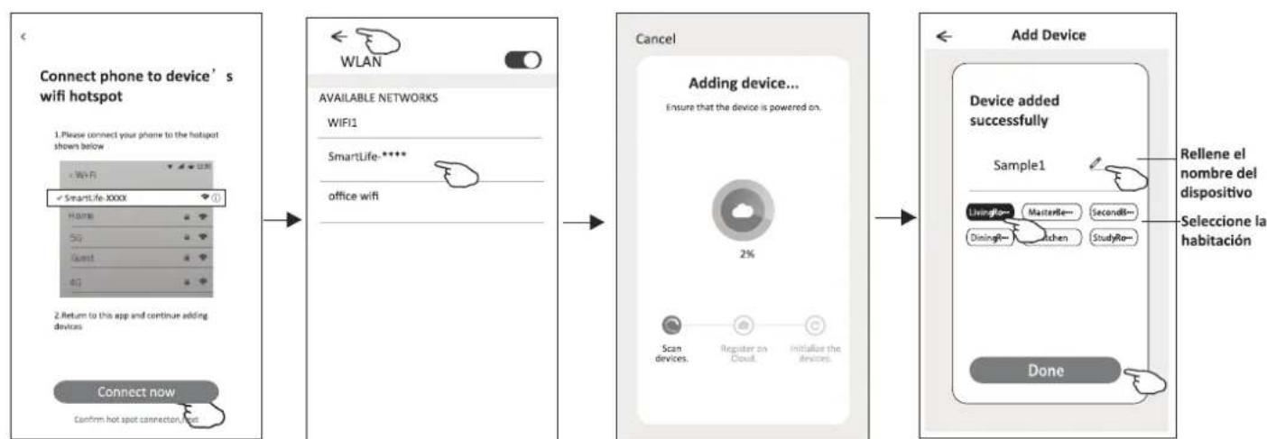
flowchart
graph LR
    A["Connect phone to device's wifi hotspot"] --> B["WLAN"]
    B --> C["AVAILABLE NETWORKS"]
    C --> D["WIFI1"]
    D --> E["SmartLife-****"]
    E --> F["office wifi"]
    G["Return to this app and continue adding devices"] --> H["Connect now"]
    H --> I["Confirm hot spot connections now"]

    B --> J["Cancel"]
    J --> K["Adding device..."]
    K --> L["Ensure that the device is powered on. 2% Scan devices, Register to Cloud, Initialize the devices"]

    L --> M["Add Device"]
    M --> N["Device added successfully"]
    N --> O["Sample1"]
    O --> P["Livingfor Masterfile Secondfile Diningfor Kitchen StudyRo Done"]

    style A fill:#f9f,stroke:#333
    style B fill:#ccf,stroke:#333
    style C fill:#cfc,stroke:#333
    style D fill:#fcc,stroke:#333
    style E fill:#cff,stroke:#333
    style F fill:#ffc,stroke:#333
    style G fill:#f96,stroke:#333
    style H fill:#9cf,stroke:#333
    style I fill:#cfc,stroke:#333
    style J fill:#fcc,stroke:#333
    style K fill:#cfc,stroke:#333
    style L fill:#fcc,stroke:#333
    style M fill:#cfc,stroke:#333
    style N fill:#cfc,stroke:#333
    style O fill:#fcc,stroke:#333
    style P fill:#cfc,stroke:#333
    style Q fill:#fcc,stroke:#333
    style R fill:#cfc,stroke:#333
    style S fill:#fcc,stroke:#333
    style T fill:#cfc,stroke:#333
    style U fill:#fcc,stroke:#333
    style V fill:#cfc,stroke:#333
    style W fill:#fcc,stroke:#333
    style X fill:#cfc,stroke:#333
    style Y fill:#fcc,stroke:#333
    style Z fill:#cfc,stroke:#333
| Fan Speed | X | ||
| high | Mid | Low | Auto |
Nota:
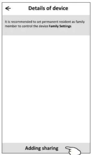
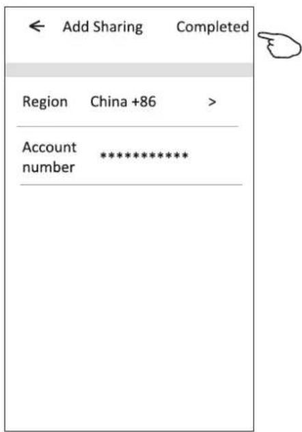
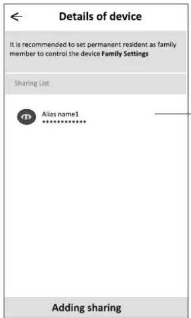
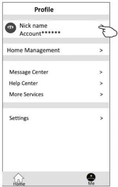
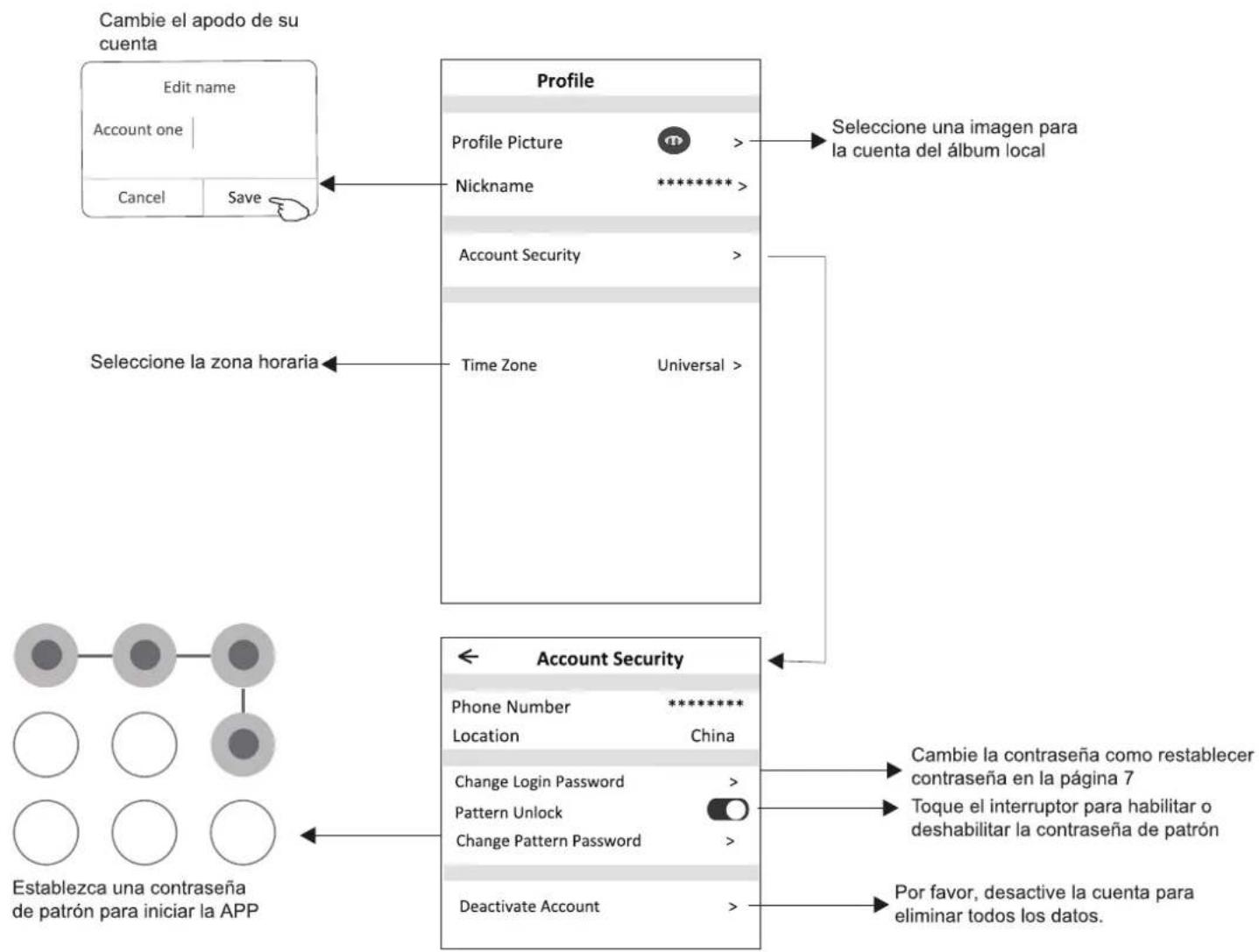
flowchart
graph TD
    A["Cambie el apodo de su cuenta"] --> B["Edit name"]
    B --> C["Account one"]
    C --> D["Cancel"]
    C --> E["Save"]
    F["Profile"] --> G["Profile Picture"]
    G --> H["Nickname"]
    H --> I["*********"]
    I --> J["Account Security"]
    J --> K["Time Zone"]
    K --> L["Universal"]
    M["Seleccione la zona horaria"] --> N["Account Security"]
    N --> O["Phone Number: *********"]
    O --> P["Location: China"]
    P --> Q["Change Login Password"]
    Q --> R["Pattern Unlock"]
    R --> S["Change Pattern Password"]
    S --> T["Deactivate Account"]
    U["Cambie la contraseña como restablecer contraseña en la página 7"] --> V["Toque el interruptor para habilitar o deshabilitar la contraseña de patrón"]
    W["Por favor, desactive la cuenta para eliminar todos los datos."] --> X["Establezca una contraseña de patrón para iniciar la APP"]
Gestión de cuenta
natural_image
Simple icon of a house with a curved arrow inside, no text or symbols present.SmartLife-SmartHome
flowchart
graph TD
    A["Scan the activation QR code from instructions or device"] --> B["Scan"]
    B --> C["or Enter Activation Code"]
    C --> D["or Enter Activation Code"]
    D --> E["*******"]
    E --> F["CANCEL CONFIRM"]
Login
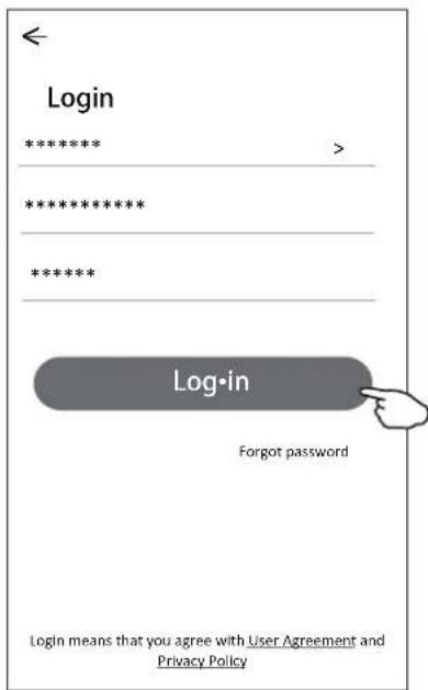
flowchart
graph TD
    A["Turn on your smart life"] --> B["Create family"]
    B --> C["Log out"]
    D["Add family Done"] --> E["Family created successfully"]
    E --> F["View family Completed"]
    G["Add Room Done"] --> H["Room Name: *****"]
    H --> I["Recommended: Living Room Master Bedroom Second Bedroom Dining Room Kitchen Study Room Porch Balcony Kids Room Closet"]
    I --> J["You can change the room settings anytime"]
    K["CANCEL CONFIRM"] --> L["Allow Smart Life to access this device's location? ALLOW ONLY WHILE IN USE ALLOW ALL THE TIME DENY"]

Nota:
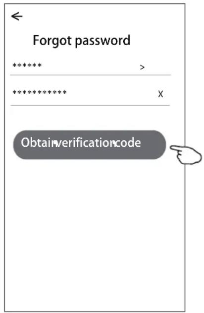
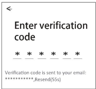
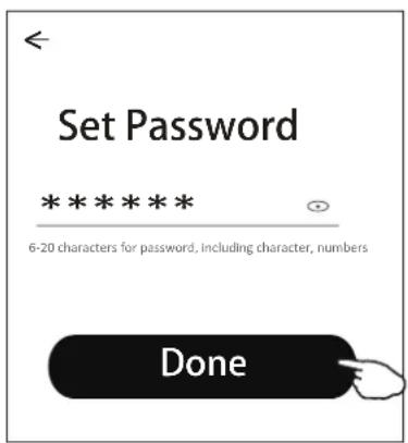
flowchart
graph TD
    A["Add Manually Auto Scan"] --> B["Select 2.4 Ghz Wi-Fi Network and enter password"]
    B --> C["Reset the device first."]
    C --> D["Add Device"]

    subgraph_A["Add Manually Auto Scan"]
        A1["Air Conditioner (BT+Wi-Fi)"]
        A2["Fresh Air Purifier"]
        A3["Split Air Conditioner"]
        A4["Security Camera"]
        A5["Window Type Air Conditioner"]
        A6["Portable Air Conditioner"]
        A7["Dehumidifier"]
        A8["Swimming Pool H/P"]
    end

    subgraph_B["Cancel"]
        B1["Select 2.4 Ghz Wi-Fi Network and enter password"]
        B2["If your Wi-Fi is 5GHz, please set it to be 2.4GHz Common router setting method"]
        B3["2.4GHz 5G"]
        B4["Password"]
        B5["Next"]
    end

    subgraph_C["Reset the device first."]
        C1["Method1: When there is a DISPLAY key on the remote control, press the DISPLAY key 6 times in the time of 8 seconds; when there is no DISPLAY key on the remote control, press the ECO key 6 times in the time of 8 seconds until the device beeps twice and the LCD screen show "CF"."]
        C2["Method2: Press the General key 9 times in the time of 8 seconds until the device beeps twice and the LCD screen show "CF"."]
        C3["CF Resetting Devices >"]
        C4["Next"] --> C3
    end

    subgraph_D["Add Device"]
        D1["Device added successfully"]
        D2["Sample1"]
        D3["LivingRo... MasterBe... SecondB... DiningRo... Kitchen StudyRo... Done"]
        D4["Renomear dispositivo"] --> D3
        D5["Selecione a sala de localização"] --> D4
    end
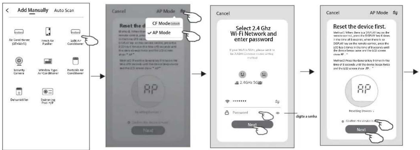
flowchart
graph LR
    A["Add Manually Auto Scan"] --> B["Reset the device"]
    B --> C["Select 2.4 GHz Wi-Fi Network and enter password"]
    C --> D["Reset the device first."]
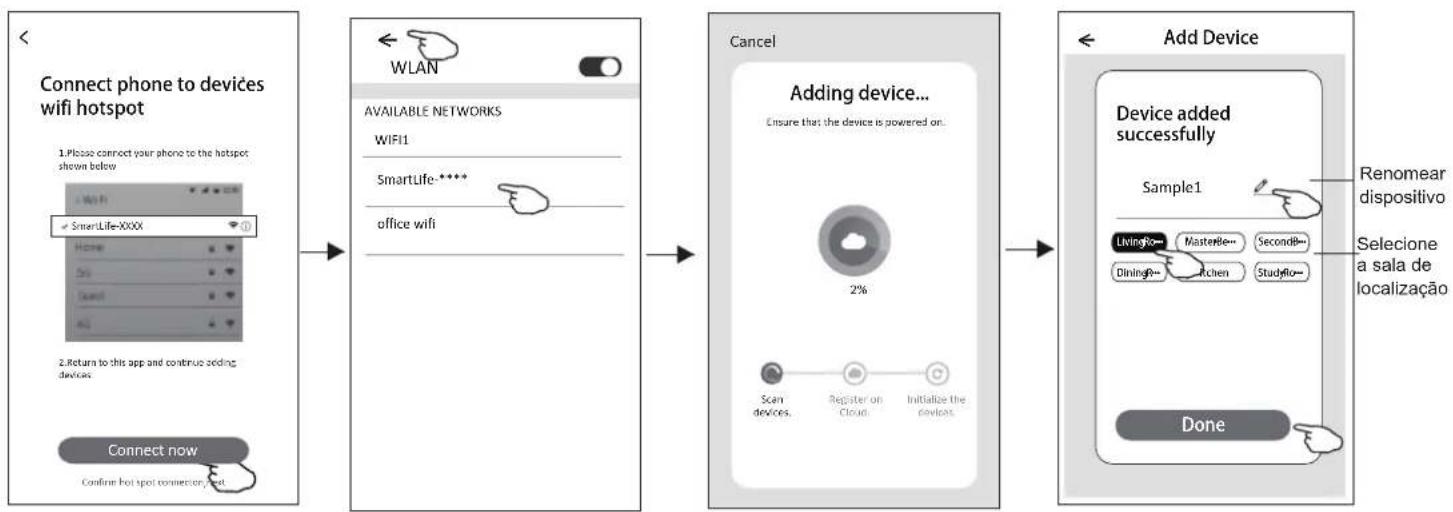
flowchart
graph LR
    A["Connect phone to devices wifi hotspot"] --> B["Connect now"]
    B --> C["Add Device"]
    C --> D["Adding device..."]
    D --> E["Cancel"]
    E --> F["Device added successfully"]
    F --> G["Renomear dispositivo\nSeleciona sala de localização"]
Nota:
| Fan Speed | X | ||
| high | Mid | Low | Auto |
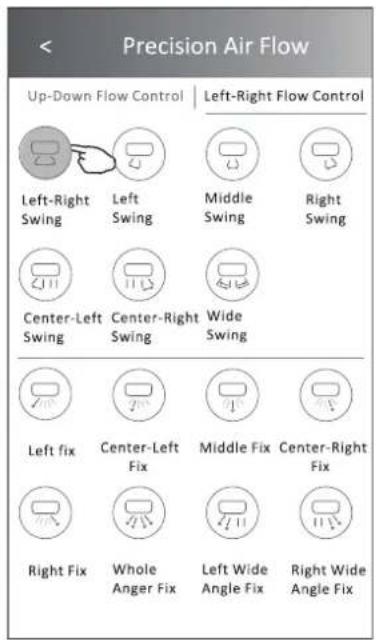
| Mode Sleep ativado |
| Cool Sim |
| Fan |
| Dry |
| Heat Sim |
| Auto |
Nota:
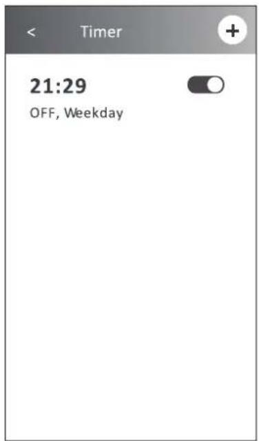
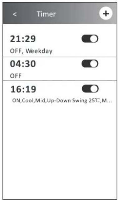
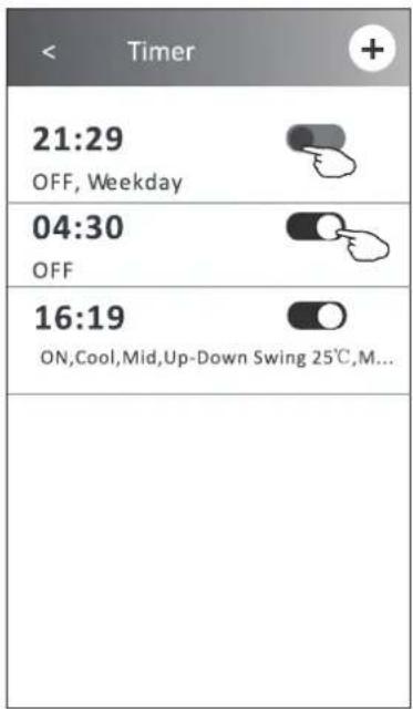
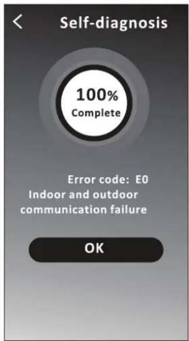
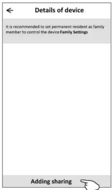
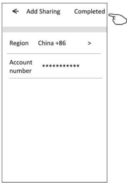
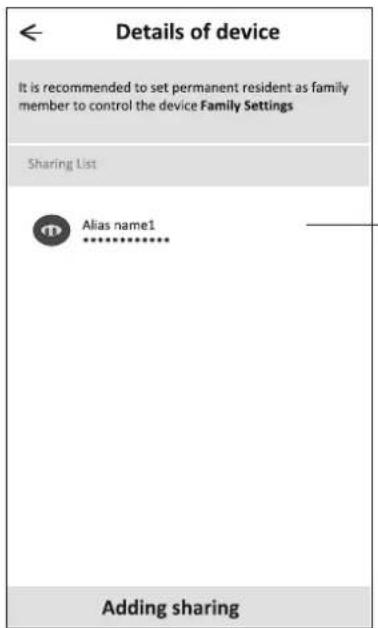
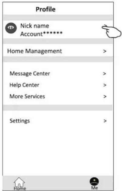
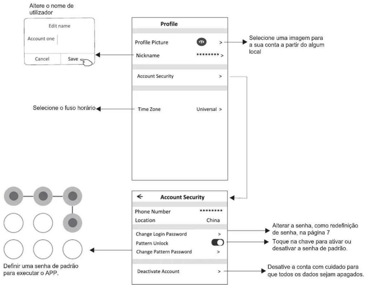
This description is applied to Air Conditioners with Wi-Fi function. Please read the manual carefully before using the product and keep it for future reference.
Let's get start!
Operation guideline. Please take below simple guideline instruction as reference.
| Operation Steps | Operation Items | New Account | Re-install APP (registered before) |
| Step 1 | Download and Install APP | YES | YES |
| Step 2 | Activate APP | YES | YES |
| Step 3 | Registration Account | YES | NO |
| Step 4 | Login | YES | YES |
| Step 5 | Add Device to control | YES | Registered Device will remain. |
Note: If you registered the account and added device before, when you re-install the APP again and login, the added device will remain.
FCC Caution (FCC ID: 2AJCLTWAC-TYWFS)
This device complies with part 15 of the FCC Rules. Operation is subject to the following two conditions: (1) This device may not cause harmful interference, and (2) this device must accept any interference received, including interference that may cause undesired operation.
Any Changes or modifications not expressly approved by the party responsible for compliance could void the user's authority to operate the equipment.
Note: This equipment has been tested and found to comply with the limits for a Class B digital device, pursuant to part 15 of the FCC Rules. These limits are designed to provide reasonable protection against harmful interference in a residential installation. This equipment generates uses and can radiate radio frequency energy and, if not installed and used in accordance with the instructions, may cause harmful interference to radio communications. However, there is no guarantee that interference will not occur in a particular installation. If this equipment does cause harmful interference to radio or television reception, which can be determined by turning the equipment off and on, the user is encouraged to try to correct the interference by one or more of the following measures:
-Reorient or relocate the receiving antenna.
-Increase the separation between the equipment and receiver.
-Connect the equipment into an outlet on a circuit different from that to which the receiver is connected.
-Consult the dealer or an experienced radio/TV technician for help.
The distance between user and device should be no less than 20cm.
CONTENTS
Wi-Fi Module specification and basic information....1
Download and Install the App....2
Activate APP....3
Registration....4
Login....6
Add device....8
Air conditioner control....10
Account management....28
Trouble Shooting....30
Wi-Fi Module specification and basic information
1. Minimum specifications on a Smart phone:
Android 5.0 version or higher
IOS 9.0 version or higher
2. Basic parameters for Wi-Fi module
| Parameters | Details |
| Network frequency | 2.400 - 2.500GHz |
| Standards of WLAN | IEEE 802.11 b/g/n(channels 1-14) |
| Protocol stack support | IPv4/IPv6/TCP/UDP/HTTPS/TLS/MulticastDNS |
| Security support | WEP/WPA/WPA2/AES128 |
| Network type support | STA/AP/STA+AP |
3. Wi-Fi module location and appearance in indoor unit
Open the front panel, the Wi-Fi module is nearby the electric box cover or on the panel.
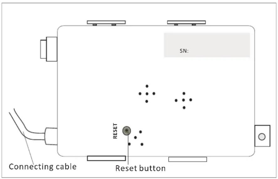

natural_image
Simple icon of a house with a curved line inside, on a dark background (no text or symbols)SmartLife-SmartHome
For Android smart phone
Method1: Please scan the QR code with a browser scanner, download and install the APP.
Method2: Open the Google "Play Store" on your smart phone and search
"SmartLife-SmartHome", ownload and install the APP.

For IOS smart phone
Method1: Please scan the QR code and follow the tips to get into "AppStore", download and install the APP.
Method2: Open the Apple "AppStore" on your smart phone and search "SmartLife-SmartHome", download and install the APP.


Note:
Please enable the permissions of Storage/Location/Camera for this APP when installing. Otherwise it will have some problems when operating.
The first time the app is used, it will need activating.
- Launch the APP "SmartLife-SmartHome" on your smart phone.
natural_image
Simple icon of a house inside a rounded square (no text or symbols)SmartLife-SmartHome
- Method1: Tap button "Scan" and scan the right Activate QR code Method2: Tap "or Enter Activation Code" in bottom of the screen, then enter the activate code and tap "CONFIRM".
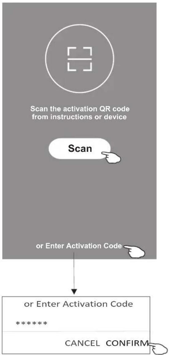
flowchart
graph TD
    A["Scan the activation QR code from instructions or device"] --> B["Scan"]
    B --> C["or Enter Activation Code"]
    C --> D["or Enter Activation Code\n*****"]
    D --> E["CANCEL CONFIRM"]
Activate QR code and activation code
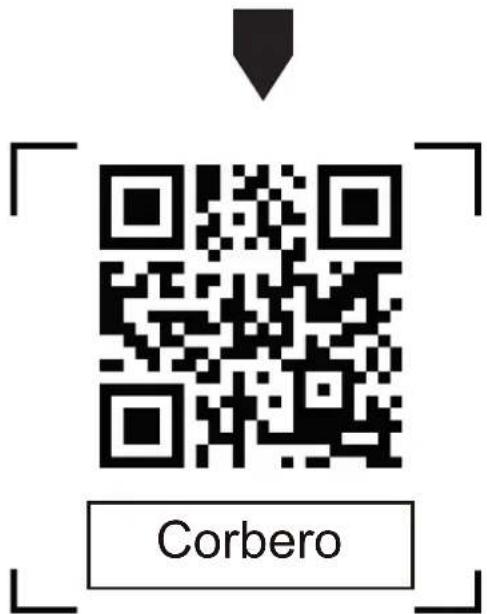
Note: Without the QR code or activation code, you can't active the APP and using it, please keep them safe.
Registration
- If you don't have any account please tap button "Register".
- Read the Privacy Policy and tap "Agree".

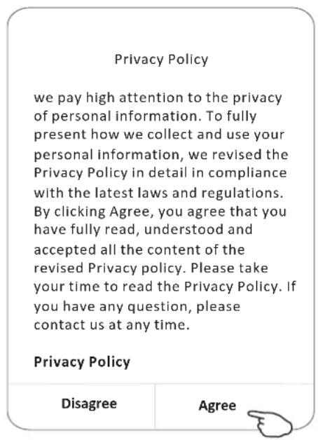
- Tap">" and choose the country.
- Enter your e-mail address.
- Tap the button "Obtain verification code".
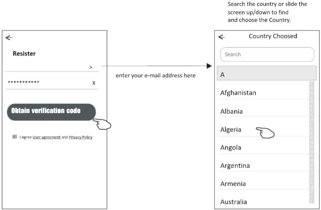
Registration
- Enter the verification code you received from e-mail.
- Set the Password with 6-20 characters including characters and numbers.
8.Tap "Done".

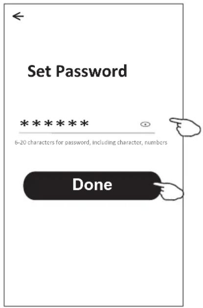
Login Login
- Tap "Log in with existing account".
- Enter your registered account and password.
- Tap "Log in" button.
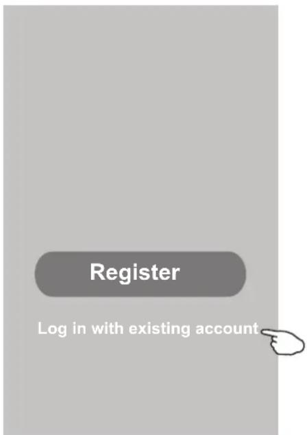
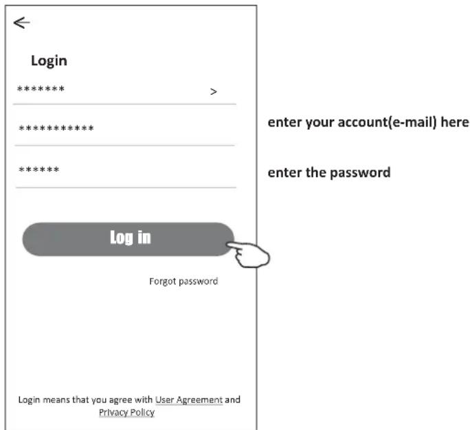
Login
The first time the APP is used, Create family is needed:
- Tap "Create family".
- Make name for the family.
- Set the location.
- Choose default rooms or add new rooms.
- Tap "Done" and "Completed".
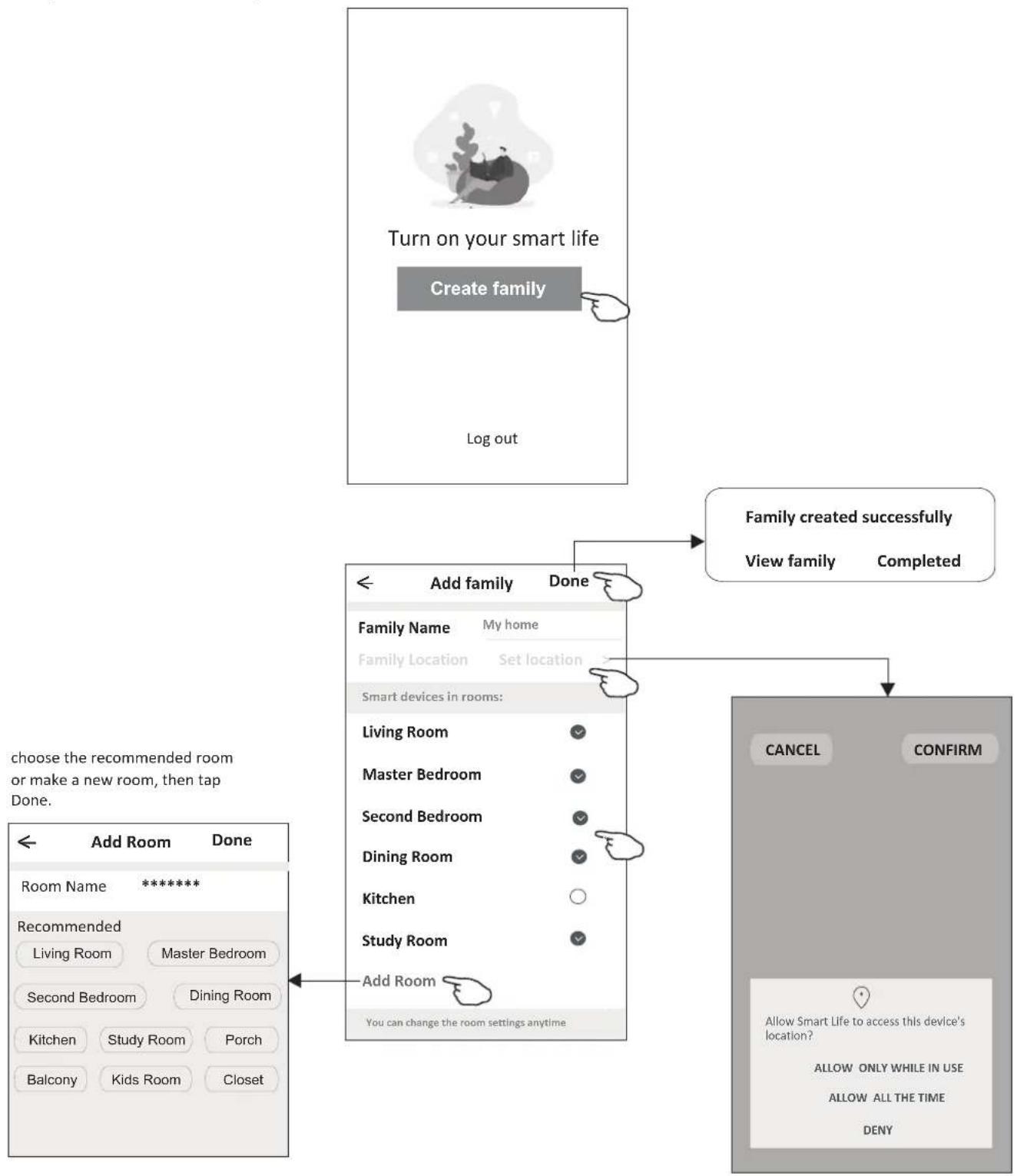
flowchart
graph TD
    A["Turn on your smart life"] --> B["Create family"]
    B --> C["Log out"]
    D["Add family Done"] --> E["Family created successfully"]
    E --> F["View family Completed"]
    G["Add Room Done"] --> H["Room Name: *****"]
    H --> I["Recommended: Living Room Master Bedroom Second Bedroom Dining Room Kitchen Study Room Porch Balcony Kids Room Closet"]
    I --> J["Do you can change the room settings anytime"]
    K["CANCEL CONFIRM"] --> L["Allow Smart Life to access this device's location? ALLOW ONLY WHILE IN USE ALLOW ALL THE TIME DENY"]

Note:
The app can open the map on your phone and you can set the location where you are.
Login
Forgot the password
If you forgot the password or you want to reset the password, operate as below:
- Tap "Forgot password".
- Enter your account(e-mail address) and tap button "Obtain verification code".
- Enter the verification code received by your e-mail.
- Set the new password and tap button "Done".
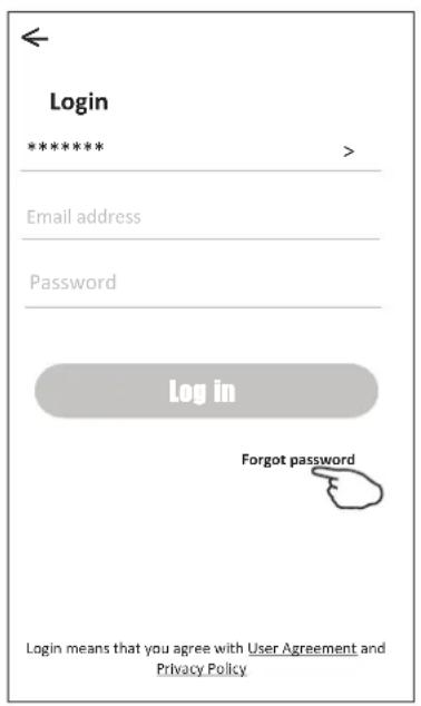
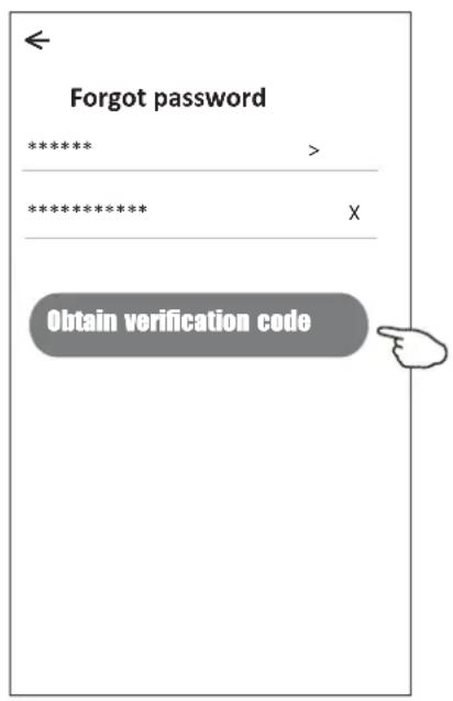
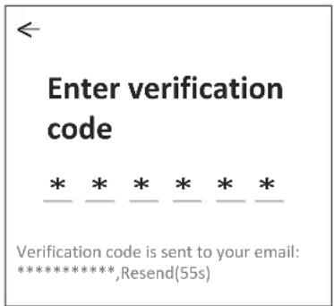
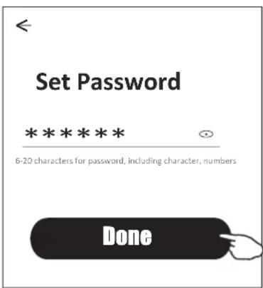
There are 2 modes CF(Quick connection) and AP(Access Point) for adding device.
CF mode
- Power on the indoor unit, no need to launch the air conditioner.
- Click "+" in the upper right corner of the "Home" screen or tap "Add device" on the room which has no device.
- Tap the "Split Air conditioner" logo.
- Input the password of the Wi-Fi which the same as your smart phone connected, then tap "Next".
- Follow the comments on the next screen to reset the Wi-Fi module then check "Confirm the device is reset" and tap"Next".
- You can see the percent rate of connecting process, at the same time PP", "SA", "AP" shining in turn on the indoor display.
"PP" means "Searching the router"
"SA" means "connected to the router"
"AP" means "connected to the server"
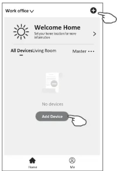
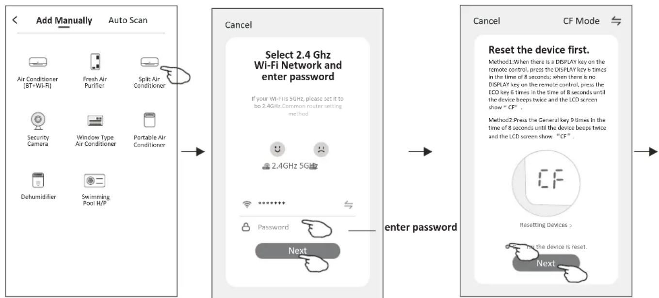
flowchart
graph LR
    A["Add Manually"] --> B["Auto Scan"]
    B --> C["Cancel"]
    C --> D["Select 2.4 Ghz Wi-Fi Network and enter password"]
    D --> E["enter password"]
    E --> F["Reset the device first."]
    F --> G["CF Mode"]
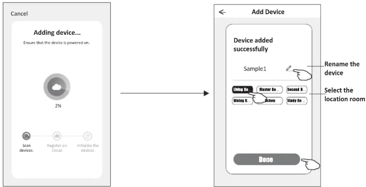
flowchart
graph LR
    A["Cancel"] --> B["Adding device..."]
    B --> C{Ensure that the device is powered on.}
    C --> D["Scan devices."]
    C --> E["Register on Cloud."]
    C --> F["Initialize the devices."]
    D --> G["2%"]
    E --> H[" "]
    F --> I[" "]
    G --> J["Add Device"]
    H --> J
    I --> J
    J --> K["Device added successfully"]
    K --> L["Sample1"]
    L --> M["Living Bo... Master Bo... Second Bo... Dining R... Kitchen Study Bo... Done"]
    M --> N["Rename the device"]
    N --> O["Select the location room"]
There are 2 methods to add the device.
2-AP mode
- Power on the indoor unit, no need to launch the air conditioner.
- Click "+" in the upper right corner of the "Home" screen or tap "Add device" on the room which has no device.
- Tap the "Split Air Conditioner" logo.
4.Input the password of the Wi-Fi which the same as your smart phone connected, then tap "Next". - Tap ⇌ in the upper right corner and choose "AP Mode" then follow the comments on the screen to reset the Wi-Fi module then check "Confirm the device is reset" and tap"Next".
- Read the instruction carefully and tap "Connect now".
- In the network setting screen, select "SmartLife-****", and tap"←".
- You can see the percent rate of connecting process, at the same time "PP", "SA", "AP" shining in turn on the indoor display.
"PP" means "Searching the router"
"SA" means "connected to the router"
"AP" means "connected to the server"
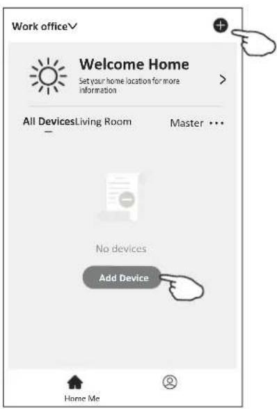
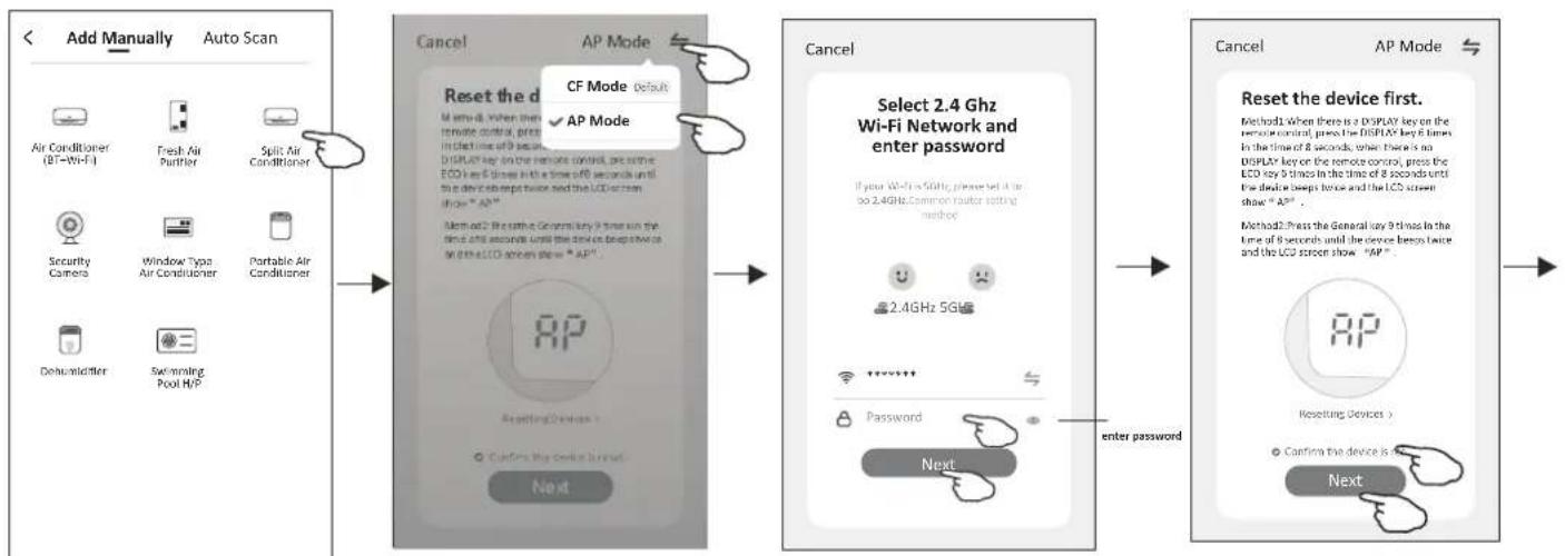
flowchart
graph LR
    A["Add Manually Auto Scan"] --> B["Reset the device"]
    B --> C["CF Mode Default"]
    C --> D["AP Mode"]
    D --> E["Select 2.4 GHz Wi-Fi Network and enter password"]
    E --> F["Next"]
    F --> G["Enter Password"]
    G --> H["Reset the device first."]
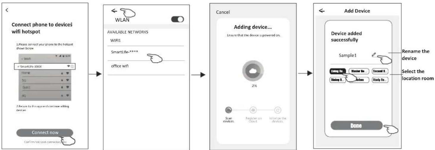
flowchart
graph LR
    A["Connect phone to devices wifi hotspot\n1. Please connect your phone to the hotspot shown below\nWIFI\nSmartLife-XXXX\nHome\n5G\nQuick\n4G\n2. Return to this app are continue adding devices\nConnect now\nConfirm hot spot connections text"] --> B["WLAN\nAVAILABLE NETWORKS\nWIFI1\nSmartLife-XXXX\noffice wifi"]
    B --> C["Cancel\nAdding device...\nEnsure that the device is powered on.\n2%"]
    C --> D["Add Device\nDevice added successfully\nSample1\nListing No... Master No... Second No... Dining It... Lesson Study No... Done"]
    D --> E["Rename the device\nSelect the location room"]
Air conditioner control
The device control screen will pop up automatically after adding the device.
The device control screen will pop up manually by tapping the device name on the home screen.
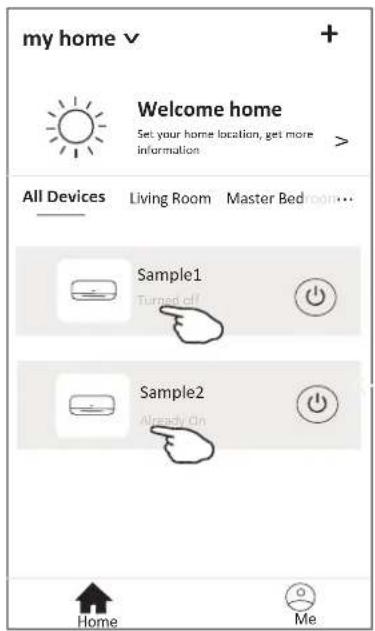
Note:
There are two different control forms base on different software or Wi-Fi module firmware. Please read the manual carefully base on the real control interface.
Control form1
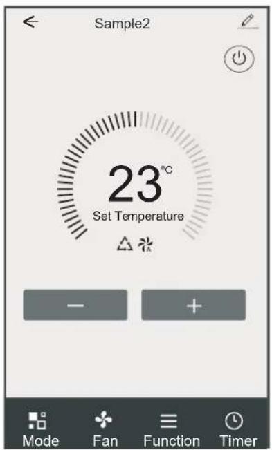
Control form2
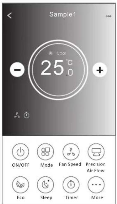
Control form1
The main control interface
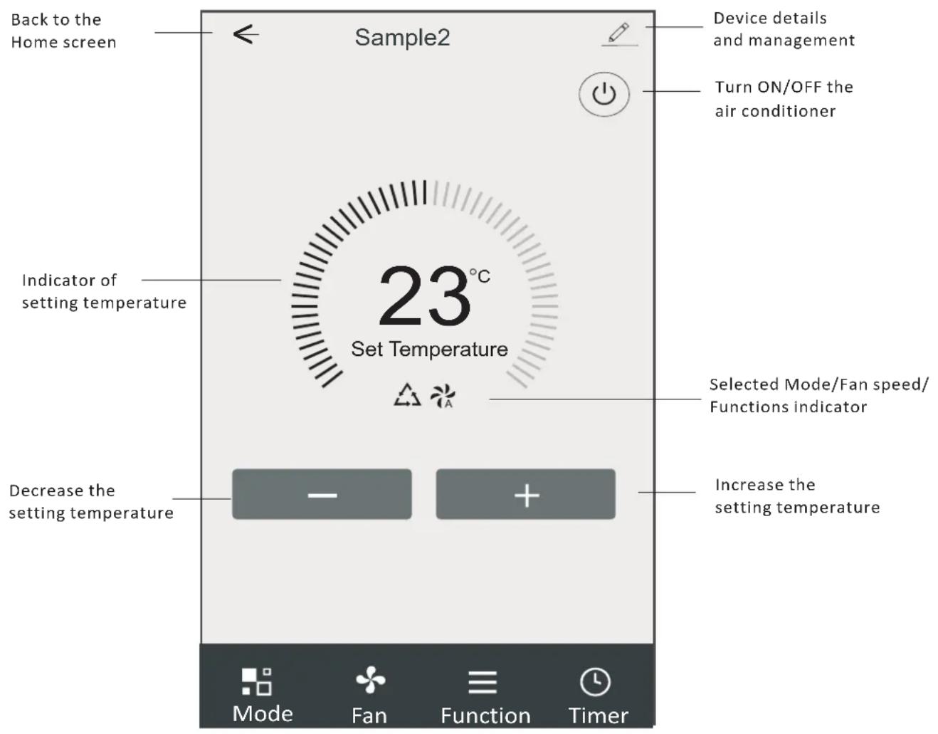
Control form1-Mode setting
- Tap Mode to pop up the Mode screen.
- Select one of the mode Feel/Cool/Heat/Dry/Fan.
- Tap anywhere around the setting temperature to cancel the Mode setting.
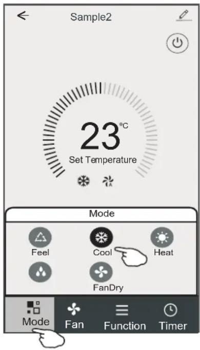
Control form1-Select fan speed
- Tap Fan to pop up the Fan screen.
- Select one of the fan speed High/med/Low/Auto.
- Tap anywhere around the setting temperature to cancel the selection.
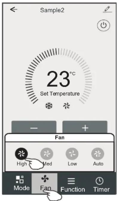
Control form1-Function setting
- Tap Function to pop up the Function screen.
- Select one of the functions Sleep/Turbo/ECO.
- Select UP-DOWN/LEFT-RIGHT for auto swing with direction of UP-DOWN/LEFT-RIGHT.
- Tap anywhere around the setting temperature to cancel the Function setting.
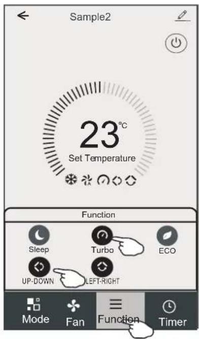
Control form1-Timer adding
- Tap Timer to pop up the Add Timer screen.
- Tap Add Timer.
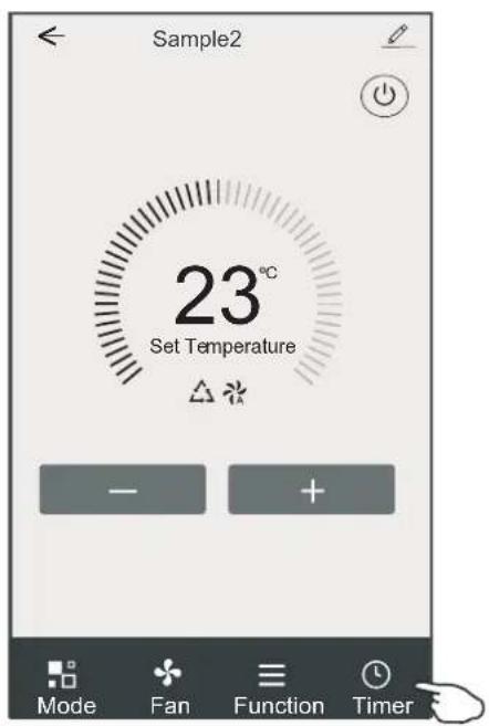
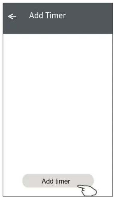
Control form1-Timer adding
- Select the time, select the repeat days and Timer on/off.
- Select the Mode/Fan speed/Function and select the setting temperature for Timer on.
- Tap Save to add the timer.
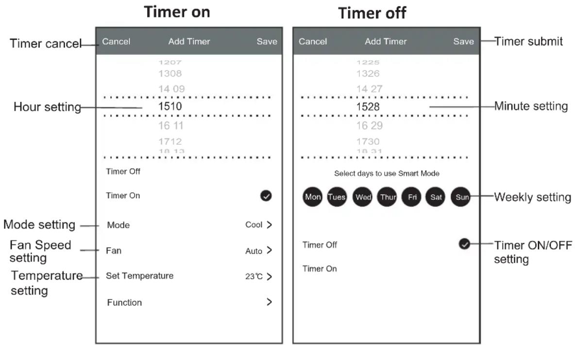
other
| Setting | Timer on Cancel | Timer on Add Timer | Timer on Save | Timer Off Timer On | Timer off Select days to use Smart Mode Mon Tues Wed Fri Sat Sun | Timer off Timer Off | Timer off Timer On | Timer off Select days to use Smart Mode Weekly Setting | Timer off Select days to use Smart Mode Weekly Setting | Hour setting | Hour setting | Hour setting Time | | :--- | :--- | :--- | :--- | :--- | :--- | :--- | :--- | :--- | :--- | :--- | :--- | :--- | | Timer cancel | 1207 | 1308 | 1409 | 1611 | 1712 | 1813 | 1510 | 1528 | 1629 | 1528 | 1629 | 1510 | | Hour setting | 1326 | 1427 | 1528 | 1730 | 1831 | 1510 | 1611 | 1730 | 1831 | 1528 | 1629 | 1510 | | Mode setting | 1225 | 1326 | 1427 | 1629 | 1730 | 1510 | 1611 | 1730 | 1831 | 1528 | 1629 | 1510 | | Fan Speed setting | 1427 | 1528 | 1629 | 1730 | 1831 | 1510 | 1611 | 1730 | 1831 | 1528 | 1629 | 1510 | | Temperature setting | 1528 | 1629 | 1730 | 1831 | 1528 | 1629 | 1730 | 1831 | 1528 | 1629 | 1730 | 1510 | | Function | 1629 | 1730 | 1831 | 1528 | 1629 | 1730 | 1831 | 1528 | 1629 | 1730 | 1831 | 1510 | Timer on/Off settingControl form1-Timer Management
- Tap the bar of timer to edit the Timer like the Timer adding process.
- Click the switch to enable or disable the Timer.
- Holdind the bar of Timer about 3 seconds and pop up the Remove Timer screen, tap CONFIRM and remove the Timer.
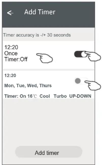
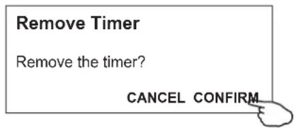
Air conditioner control
Control form2
The main control interface
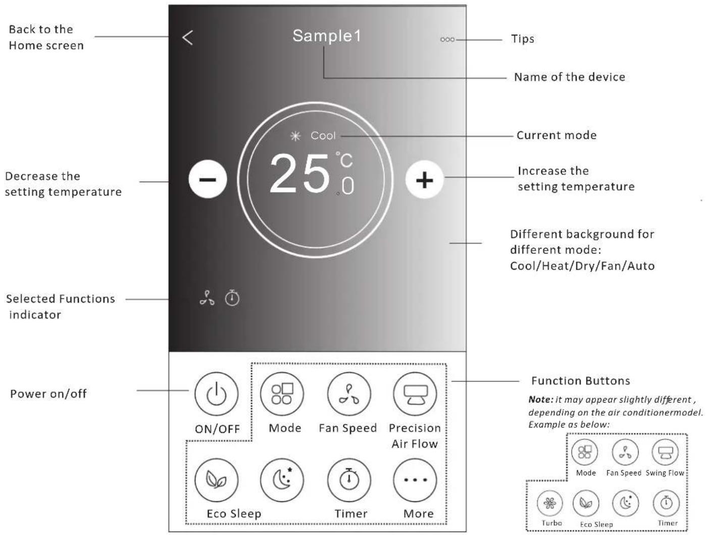
Air conditioner control
Control form2-Mode setting
- Tap the Mode button.
- There are 5 modes on the Mode screen, tap one button to set the Air conditioner working mode.
- Tap the X button to back the main control screen.
- The mode and background will change on the screen.
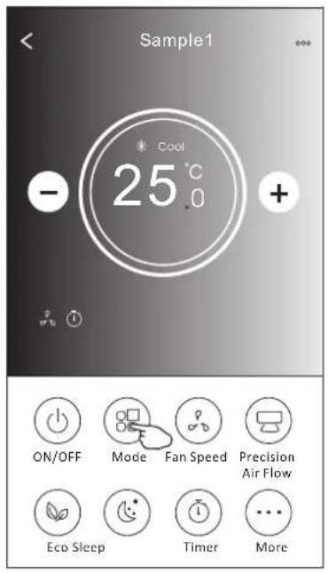
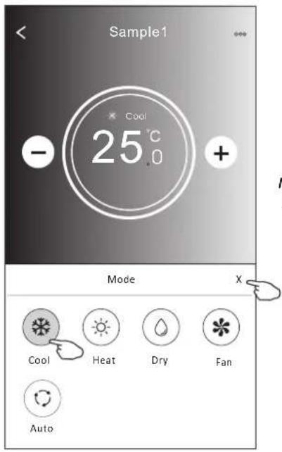
Note: please read the details of each mode in the user manual to control more comfortable.
Control form2-Fan speed selection
- Tap the Fan speed button.
- Choose your desired fan speed and tap it.
- Tap the X button to back the main control screen.
- The selected fan speed indicator will appear on the screen.
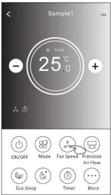
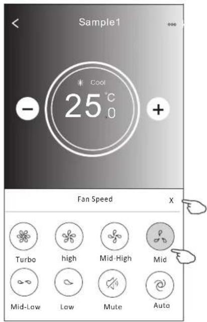
| ModeFan Speed | |
| Cool | All speeds |
| Fan | All speeds |
| Dry | |
| Heat | All speeds |
| Auto | All speeds |
Note:
Fan Speed can't be adjusted on Dry mode.
Note: Fan Speed screen may appear slightly different, depending on the air conditioner model.
Example as below:
| Fan Speed | X | ||
| high | Mid | Low | Auto |
Control form2-Air Flow control
- Tap the Precision Air Flow button or Swing Flow button.
- Choose your desired air flow and tap it.
- Tap the X button to back to the main control screen.
- The selected air flow indicator will appear on the screen.
Note: For some models without auto Left-Right wind, If you active it, you will hear a beep, but no any actions.
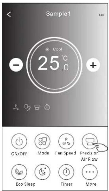
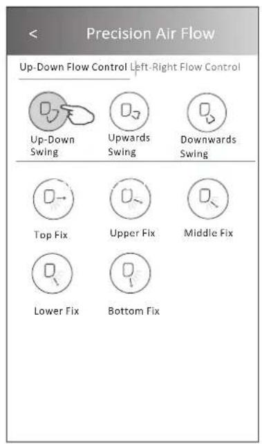
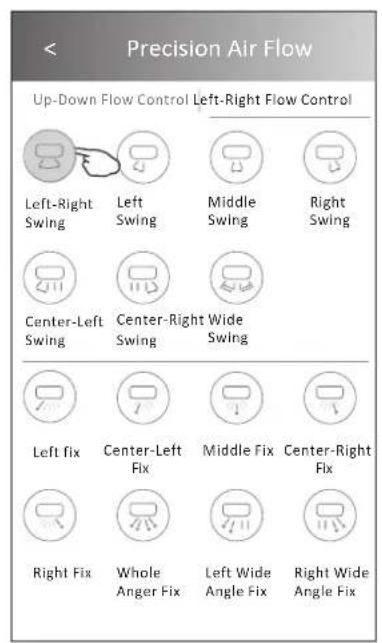
Note: The Main controlscreen and Air Flowscreen may appear slightly different, depending on the airconditioner model. Example as below:
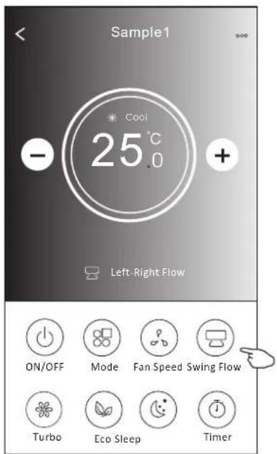
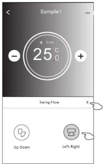
Air conditioner control
Control form2-ECO function
- For Eco function, just tap the button to activate the function, the button will be lighting and the indicator will appear on the screen.
- Tap again to disable the function.
- Temperature controlled for some air conditioner model: In Cooling mode, the new setting temperature will ≥slant26 . ^ C In heating mode, the new setting temperature will ≤slant25 . ^ C
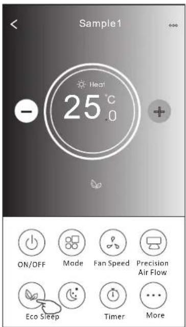
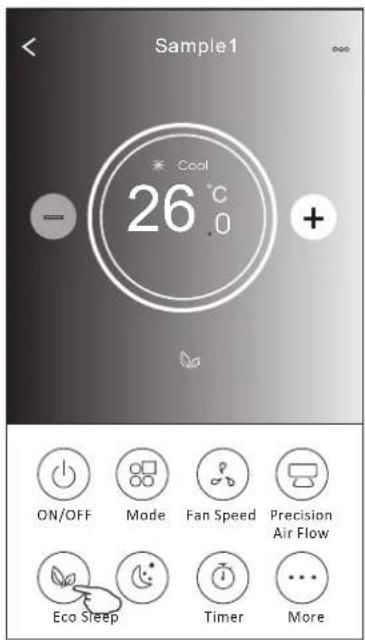
| Mode | ECO enabled |
| Cool | Yes |
| Fan | |
| Dry | |
| Heat | Yes |
| Auto |
ECO is disabled on Fan/ Dry/Auto mode.
Note: The Main control screen and ECO control method may appear slightly different, depending on the airconditioner model. Example as below:
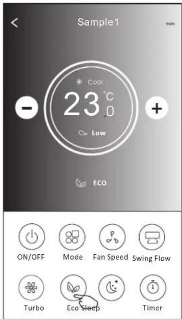
Note:
ECO is disabled on Turbo/Sleep mode too for some air conditioner model.
Air conditioner control
Control form2-Sleep function
- Tap the Sleep button.
- Choose your desired sleep mode and tap it.
- Tap the X button to back to the main control screen.
- The selected sleep mode indicator will appear on the screen.
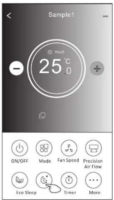
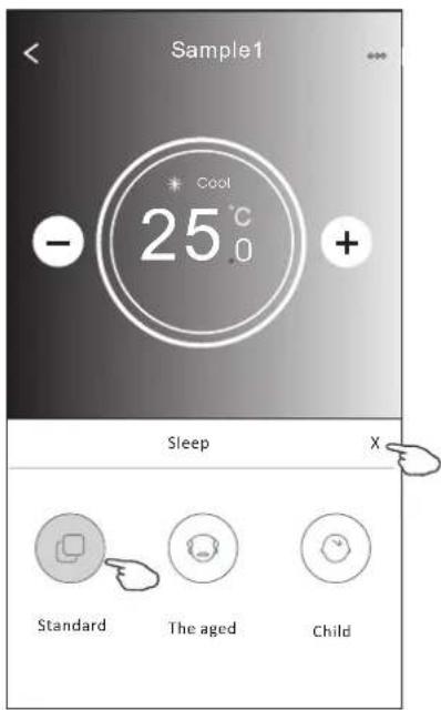
| Mode | Sleep enabled |
| Cool | Yes |
| Fan | |
| Dry | |
| Heat | Yes |
| Auto |
Sleep is disabled on Fan/ Dry/Auto mode.
Note:
The Main control screen may appear slightly different, depending on the air conditioner model. Example as below:
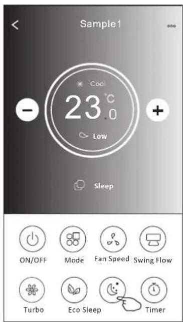
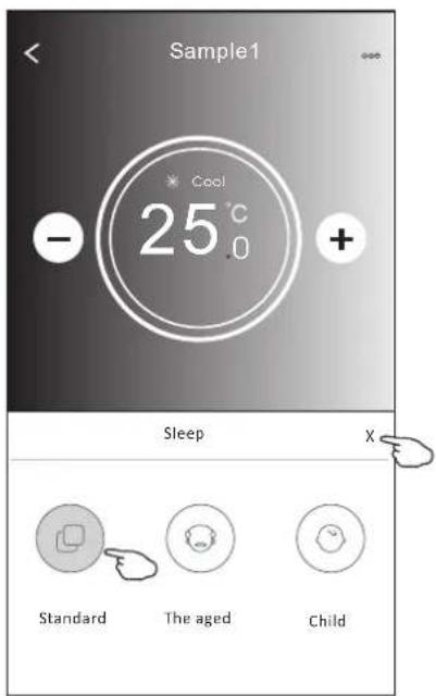
Note:
Sleep is disabled on Turbo/Sleep mode too for some air conditioner model..
Air conditioner control
Control form2-Timer(on) setting
- Tap the Timer button.
- Tap + in the upper right corner of the Timer main screen.
- Choose the Time/Repeat/Switch OFF then tap Save.
- The timer(off) will appear on the Timer main screen.
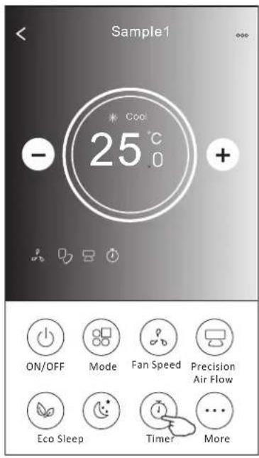
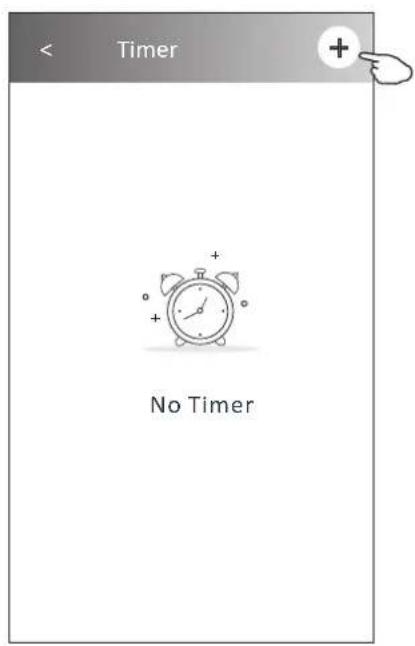
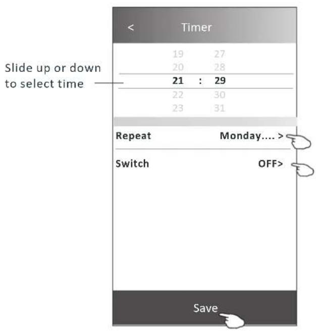
Tap repeat> then tap your desired repeat days or Once, then tap Confirm your selection.
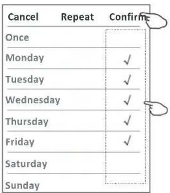
Tap Switch> then slide the screen to choose ON and Confirm.
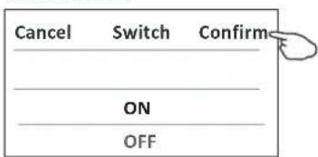
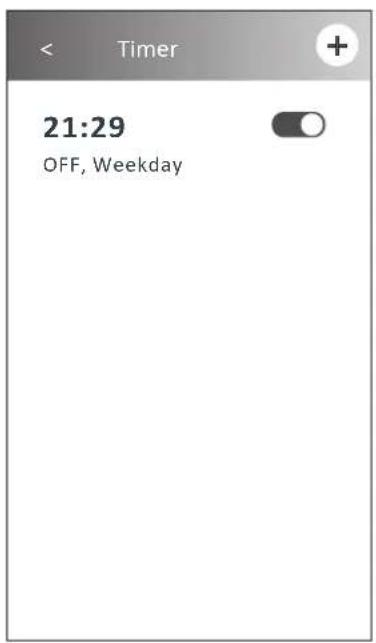
Air conditioner control
Control form2-Timer(off) setting
- Tap the Timer button.
- Tap + in the upper right corner of the Timer main screen.
- Set the Time/Repeat Date/Switch(ON)/Temperature/Mode/Fan speed/Air Flow as your desired and then tap Save.
- The timer will appear on the Timer main screen.
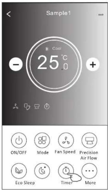
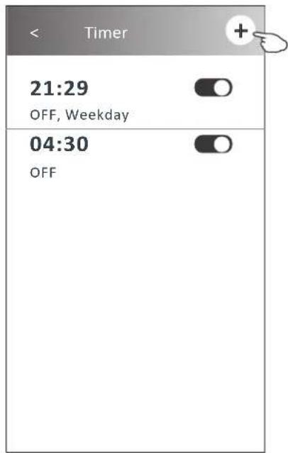
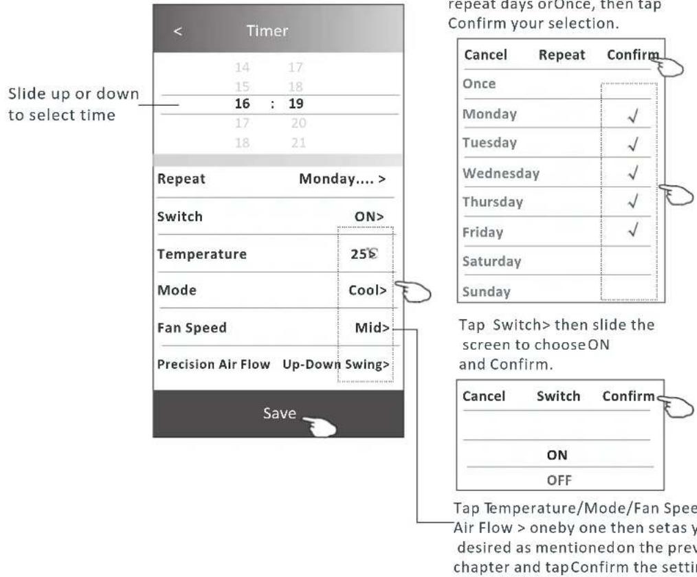
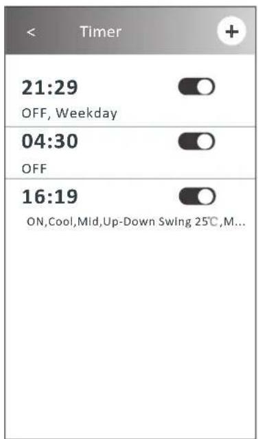
Air conditioner control
Control form2-Timer management
1. Change the Timer setting:
Tap anywhere of the timer list bar except the switch bar to get into the Timer setting screen, change the setting and then tap save.
2. Enable or Disable the Timer:
Tap the left of the switch to disable the Timer.
Tap the right of the switch to enable the Timer.
3. Delete the Timer:
Slide the list bar of the Timer from right to left until Delete button appear, then tap delete.
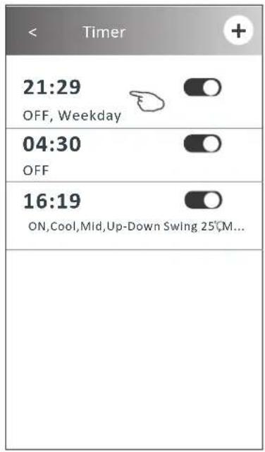
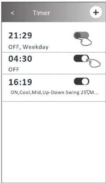
Slid left to disable the Timer.
Slid right to enable the Timer.
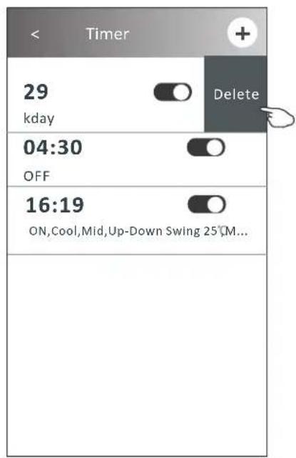
Control form2-More functions
- Tap the More button to operate additional functions if it appears on the screen.
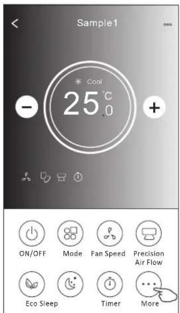
Note: Some air conditioner model don't have the more button.
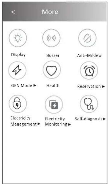
Note: The appearance maybe different, some icons will be hidden if the air conditional do no have this function or do not enable on the current mode.
- Tap the to switch on/off the indoor LED display."
Display - Tap the " ( ) " to switch on/off the buzzing when operating through Wi-Fi APP.
Buzzer - Tap the " ( ) " button to activate the Anti-Mildew function, if it is available on the screen.
Anti-Mildew
After AC turning off, it will start drying, reduce residual moisture and prevent mould, after function finish, it will automatically turn off.
- Tap the "button to switch on/off the healthy function, if it is available on the screen.

Health
It activate the antibacterial ioniser function. This function only for models with the ioniser generator.
- Tap the "GEN Mode" button, if it is available on the screen.
In this Mode, you can choose one of the three levels of current.
The air conditioner will maintain proper current to save energy.
GEN Mode▶
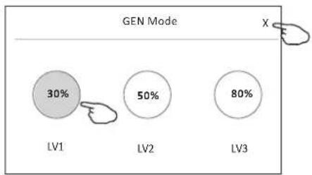
pie
GEN Mode | Category | Value (%) | |---|---| | LV1 | 30 | | LV2 | 50 | | LV3 | 80 | XAir conditioner control
Control form2-More functions
- Tap the "Electricity Monitoring" button if it is available on the screen.
In this function, you can monitor the air conditioner electricity consumption.
Electricity Monitoring
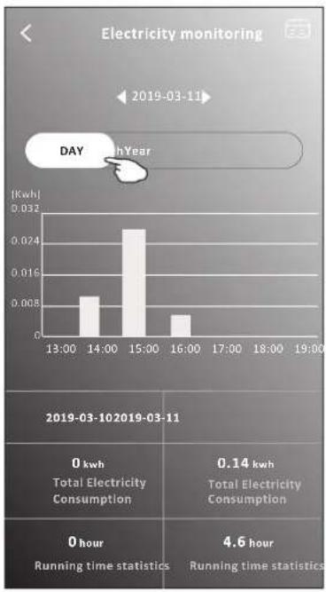
bar
| Time | Electricity Consumption (kwh) | |---|---| | 13:00 | 0.005 | | 14:00 | 0.024 | | 15:00 | 0.008 | | 16:00 | 0.003 | | 17:00 | 0.000 | | 18:00 | 0.000 | | 19:00 | 0.000 | 2019-03-10/2019-03-11 Total Electricity Consumption 0 kwh Total Electricity Consumption 0 hour Running time statistics 4.6 hour 2019-03-11 Day Year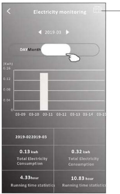
bar
Electricity monitoring | Date | Electricity Consumption (kwh) | | :--- | :--- | | 03-09 | 0.13 | | 03-10 | 0.32 | | 03-11 | 0.16 | | 03-12 | 0.08 | | 03-13 | 0.04 | | 03-14 | 0.02 | | 03-15 | 0.01 | 2019-022019-03 Total Electricity Consumption 4.33hour Running time statistics 10.83 hourYou can tap this button to pop up the calender then select the date.
- Tap the " button, if it is available on the screen.
Self-Cleaning
Check the details of the Self-Cleaning function on User Manual.
- Tap the "8°C Heat" button, if it is available on the screen.
This function help keep the room temperature over 8^ C Check the details of the 8^ C Heat function on User Manual.

8°C Heat
- Tap the "Reservation" button, if it is available on the screen.
You can set the time, repeat day, temperature, mode, fan speed, air flow as you desired and then tap Save to activate the function.
The air conditioner will automatically reach your settings at the appointment time.
Reservation▶
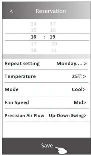
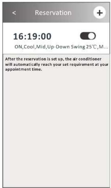
Air conditioner control
Control form2-More functions
- Tap the "Self-diagnosis" button, if it is available on the screen.
The air conditioner will automatically diagnosis itself and indicate the Error code and the problem instructions if possible.
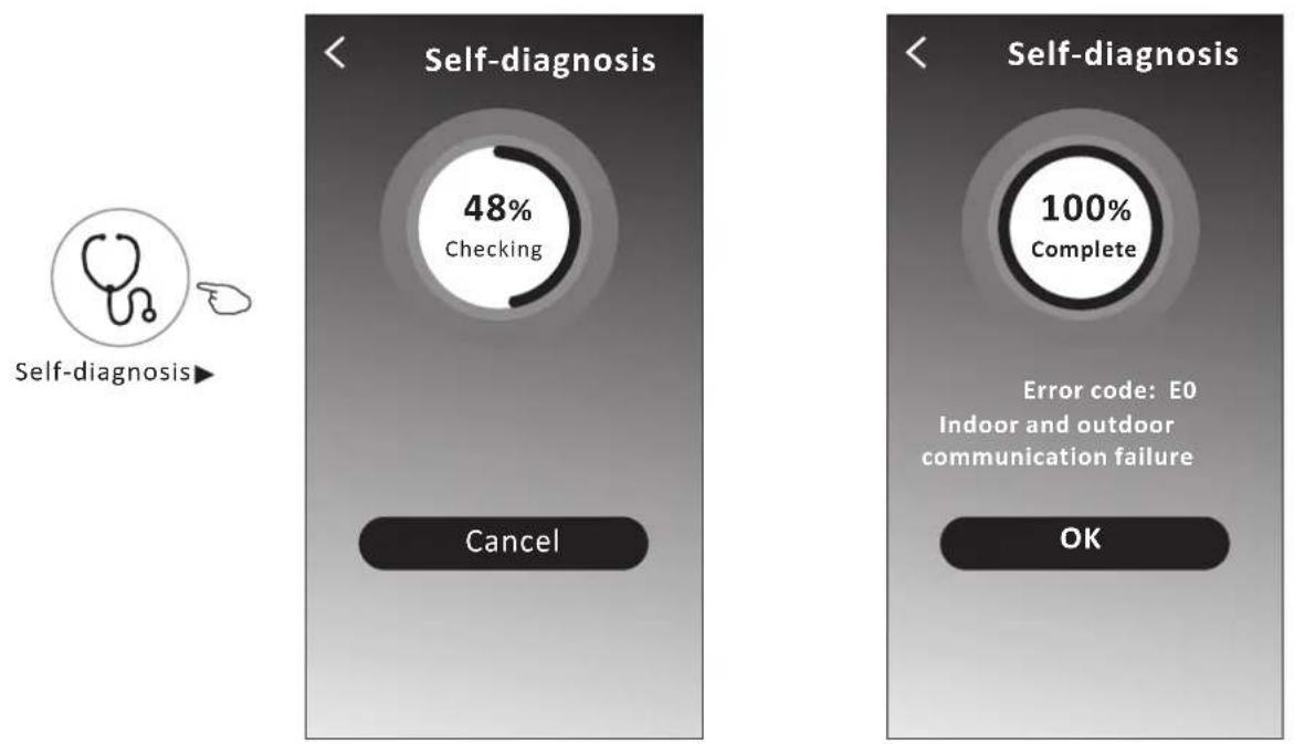
- Tap the " ( ) " button if it is available on the screen.
Photosensitive
This function allows the air conditioner to turn on/off the display automatically according to the light intensity.
- Tap the " (=)" button if it is available on the screen.
Soft Wind
In this function, the air conditioner will blow soft airflow through the micro holes on the deflector.
Air conditioner control
Device details and management
Tap on control form1 or tap ... on control form2, get into the device details screen. Here you can get some useful information and sharing the device to other accounts. Check the following pictures and instructions carefully.
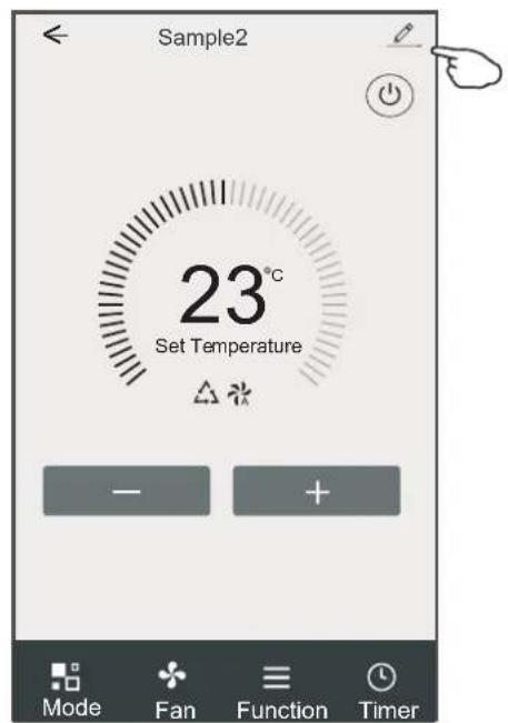
Control form2Control form1
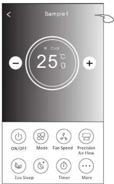
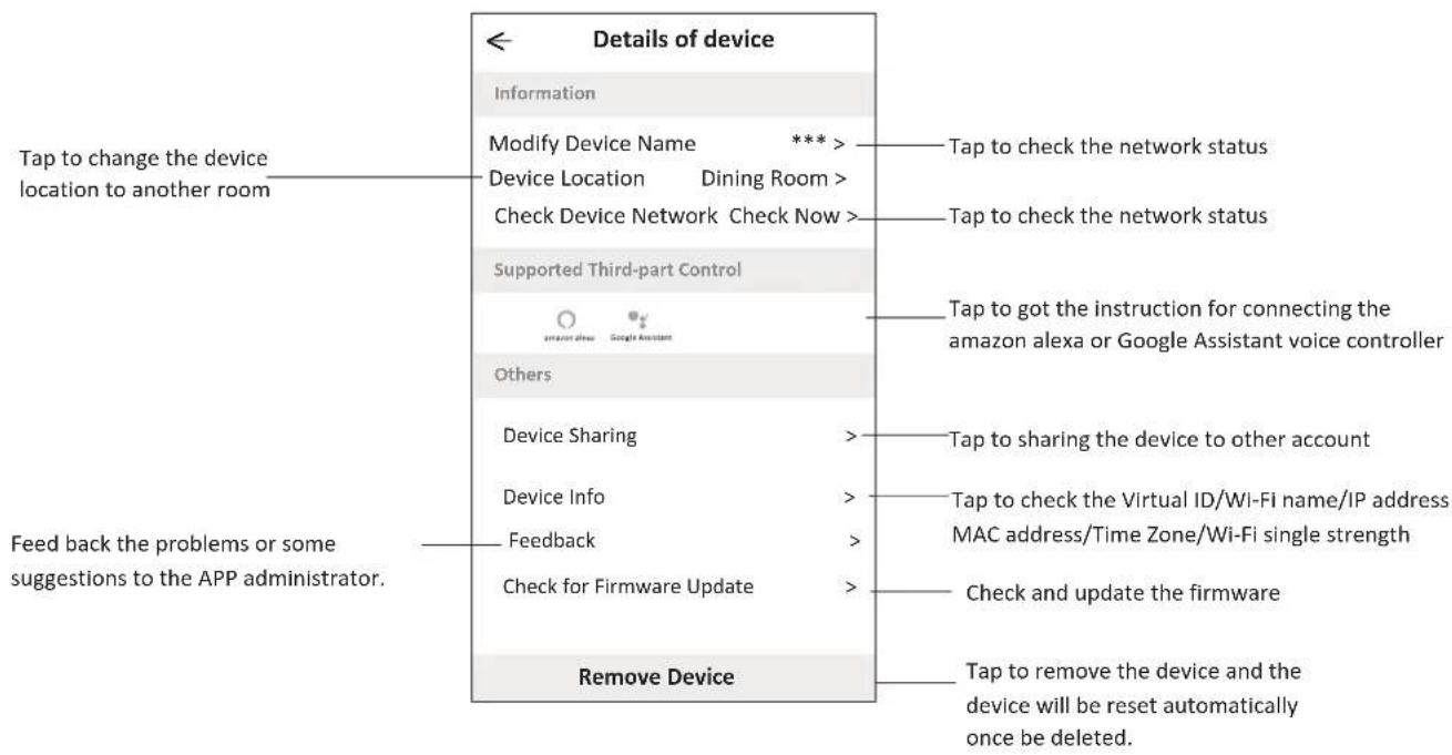
Device details and management
How to share the devices to other accounts?
- Tap "Device Sharing" and pop up Device Sharing screen.
- Tap "Add Sharing".
- Select the region and enter the account which you want to sharing.
- Tap "Completed", the account will appear on your sharing list.
- The received sharing members should hold pressing the home screen and slide down to refresh the device list, the device will appear on the device list.
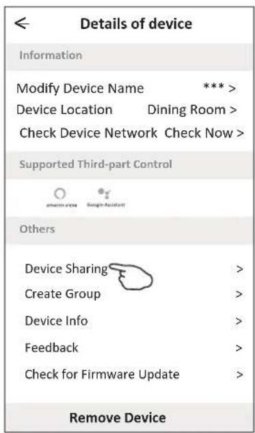
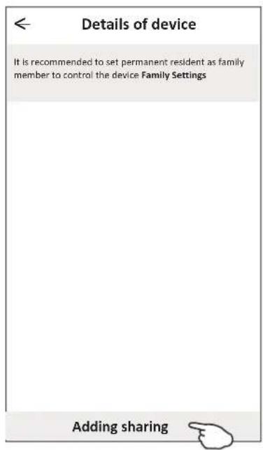
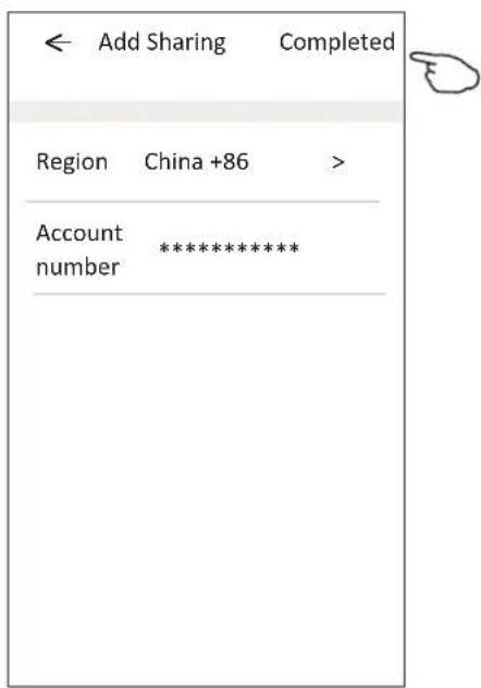
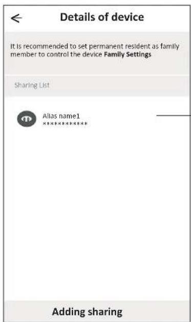
Hold the bar about 3s then you can delete the sharing account.
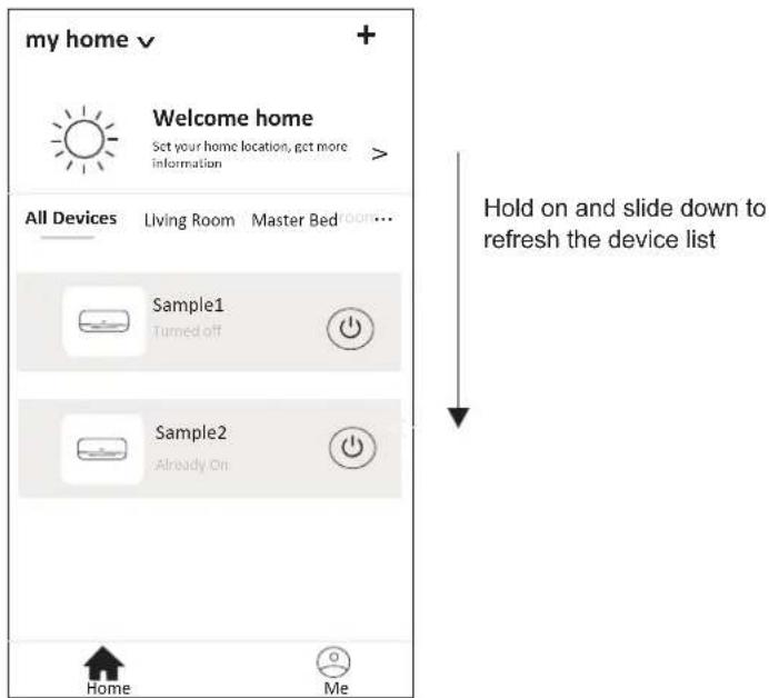
Account Profile setting
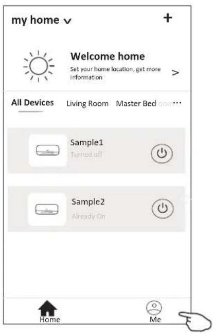
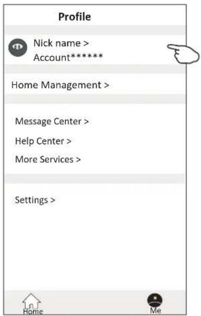
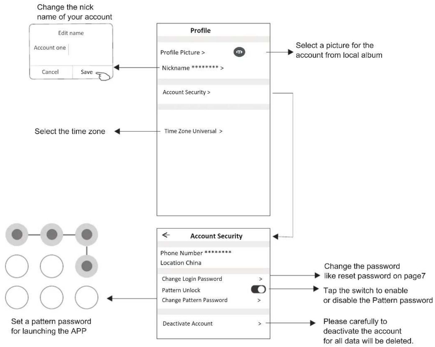
flowchart
graph TD
    A["Edit name\nAccount one"] --> B["Save"]
    C["Profile"] --> D["Select a picture for the account from local album"]
    E["Time Zone Universal"] --> F["Select the time zone"]
    G["Account Security"] --> H["Change the password like reset password on page7"]
    G --> I["Tap the switch to enable or disable the Pattern password"]
    G --> J["Please carefully to deactivate the account for all data will be deleted."]
Account management
Home(Family) management
- Tap the name of home at the left upper corner of the Home Screen and select the Home Management. Or tap Me and tap Home Management.
- Tap one of the families in the family list and get into Family Settings screen.
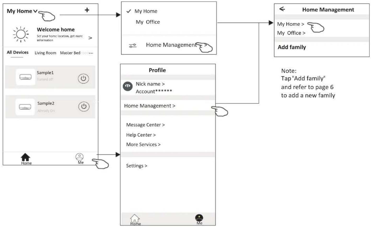
flowchart
graph TD
    A["My Home"] -->|+| B["Welcome home"]
    B --> C{✓ My Home}
    C --> D["My Office"]
    C --> E["Home Management"]
    E --> F["Add family"]
    G["Profile"] --> H["Nick name > Account*****"]
    H --> I["Home Management >"]
    I --> J["Message Center > Help Center > More Services >"]
    J --> K["Settings >"]
    K --> L["Home"]
    K --> M["Me"]
- Set the family as the following indicators.
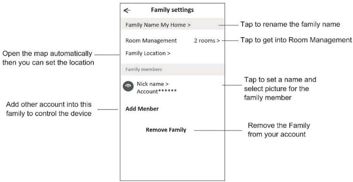
Notice
- For technical update, there is maybe deviation of the actual items from what is on the manual. We express our apologies. Please refer to your actual product and APP.
- Smart air conditioner APP can be altered without notice for quality improvement and also be deleted depending on the circumstances of manufacturing firms.
- In case Wi-Fi signal strength is weakened, smart App may be disconnected. So make sure the indoor unit near to wireless router.
- DHCP server function should be activated for wireless router.
- The internet connection may fail because of a firewall problem. In this case, contact your internet service provider.
- For smart phone system security and network setting, make sure Smart air conditioner APP is trusted.
Trouble Shooting
| Description | Analysis of cause |
| Air conditioner can't be configured successfully | 1. Check the mobile connected WLAN router SSID and password is correct;2. Check whether there are additional settings of WLAN router as shown below.1) Firewall by router itself or by PC2) MAC address filtering3) Hidden SSID4)DHCP serverReboot WLAN router, mobile device and air conditioner (WLAN module) and connect air conditioner by CF mode again. Before rebooting, check nobody has already connected to same air conditioner. |
| Mobile can't control air conditioner | 1. When air conditioner (WLAN module) is rebooted and app displays Device remove, ignoring this confirmation will lead to mobile device losing control permission of the air conditioner.You will need to connect the air conditioner by CF mode again.2. In case of power failure, mobile device will lose control permission of air conditioner for 3 minutes after power failure. (Notification will now show up on the mobile device.)If you cannot control the app (air conditioner) even after power restored, you will need to connect the air conditioner by CF mode again. |
| Mobile can't find air conditioner | 1. App display Air conditioner Device offline. Please check the following conditions.1)The air conditioner has been reconfigured.2)Air conditioner out of power.3)Router out of power.4)Air conditioner can't connect to router.5)Air conditioner can't connect to network through the router.6)Mobile device can't connect to network.2. After adding the device, it disappears in device list .Hold and slide down to refresh the device list. If it has no change, shut down the app and start again. |
CERTIFICADO DE GARANTÍA
The presentation of the purchase invoice accompanied by this guarantee certificate is essential.
Covered Risks.
This appliance is guaranteed against any malfunction, provided that it is intended for domestic use, proceeding to its repair within the warranty period and only by the authorized SAT network.
Our Corberó appliances have the manufacturer's legal warranty that covers any breakdown or defect for 36 months, from the invoice date of January 1, 2022. If necessary, we take care of any possible incident whenever it is due to a defective component or manufacturing fault. Warranty Exceptions
Warranty Exceptions
- That the date of the certificate does not coincide with the date of sale of the original invoice.
• Faults produced by blow, by fall or any other cause of force majeure.
• If the device has been manipulated by unauthorized personnel. - Faults produced or derived as a consequence of improper use, installation defects, or modifications to the device that alter its operation.
- Start-up, maintenance, cleaning, components subject to wear, lamps, aesthetic parts, oxidation, plastics, rubbers, housings and crystals.
- Microwave ovens (with the exception of built-in ones) and tabletop ovens in the event of any incident of operation, they must be taken to the nearest technical service by the customer. They are not collected or repaired at home.
- Electric thermos guarantee. 3-year warranty including travel and labor costs that correspond to the repair of the product, having to have maintenance once every 12 months. Especially if you have installed a gas appliance, keep in mind as the owner of the installation, the obligation to carry out a complete review of the equipment, (according to Royal Decree 238 / 2013, of April 5. RITE. IT3, M. Lo thermos electrical and boilers that include hot water storage tanks, for the benefit of the Guarantee to apply, it is mandatory that the magnesium anode is operational and that it performs the protection function adequately. For this, it is recommended that the anode be checked biannually by the Official Service and is renewed when necessary Periodicity that must be annual in those areas with critical waters (CaCO3 content greater than 200mg/L, that is, from 20°fH of hardness) Deposits without the correct state of the protection anode are not covered by the warranty Regardless of the type of tank or product, all heating or DHW overpressure valves must be channeled to avoid damage and n the house due to water discharges. The product warranty does not cover damages caused by not channeling the water spilled by this valve.
- Guarantee of pellet stoves, Gas Stoves, it is necessary to have the start-up accreditation from Corberó SAT, to benefit from the 3-year guarantee service.
"THESE EXCEPTIONS VOID THE WARRANTY, THE REPAIR BEING CHARGED TO THE CUSTOMER"
Period covered in devices according to the law of guarantees in the sale of consumer goods Current law is "RD 7/2021"
Official Technical Service:
911 08 08 08
CERTIFICADO DE GARANTIA
-
The Warranty lasts three years on the device and seven on the compressor (for the compressor after three years the warranty includes only the supply of the part), starting from the date of supply and/or installation. No one is authorized to modify the warranty period or grant other verbal or written guarantees.
-
The Guarantee covers all components of the device and includes the free repair and supply of any part due to manufacturing defects. The replacement or repair of defective parts does not modify the duration of the warranty.
-
In the event of replacement of the device due to a manufacturing defect, in the opinion of the manufacturer or its legal representative that it cannot be repaired, the warranty of the new device will continue until the end of the original equipment warranty.
-
The Warranty does not cover components damaged due to transportation, lack or error in maintenance, supply of electrical fluid that does not comply with current regulations, due to manipulations carried out by unauthorized operators or for reasons not attributable to the manufacturer. Interventions caused by installation defects are also excluded from the Guarantee.
-
The Guarantee is validated if:
a) The device has been installed in Spain or Portugal in accordance with current regulations and with the instructions of the installation and user manual.
b) The device has preventive maintenance by the Technical Assistance Personnel authorized, according to the recommendations of the installation and user manual.
c) The device has been installed by an authorized installer.
- It is considered that the Guarantee expires:
a) Tampering by personnel not legally authorized to do so.
b) Electrical or hydraulic installation not in compliance with current standards or as described in the installation and user manual.
c) Use of methods other than those described in the installation and user manual or for purposes other than those for which the device is intended.
d) Inability of the user to show the purchase and installation invoice to authorized personnel from an authorized installer.
-
The importer is liable before the law for damages caused to people or things due to construction defects in their devices as long as the conditions set out above are met. In any case, damage caused by the suspension of operation of the device is excluded.
-
When the device must be repaired in the Technical Assistance Service workshop indicated by the importer, the corresponding transportation risks will be borne by the user in the case of direct shipping and by the SAT in the case of removal from the User's home. In the case of a customer without an open account with the importer, before the repair you must make a payment to cover the repair if it is outside the warranty due to improper use or poor installation.
-
They are excluded from the guarantee, as they are not part of it.:
- The replacement of consumable materials due to operation, such as, but not limited to, and not limited to, refrigerant gas, compressor oil, oil filters, etc.
- Extraordinary expenses caused by difficult access to the unit (cranes, scaffolding, assembly and disassembly of these devices, permits, preventive resources, etc.), being the responsibility exclusive of the owner of the installation to guarantee safe and sufficient access to the installed unit/s.
- The issues that arise as a consequence of the application or interpretation of this guarantee must be resolved before the Courts of Justice of Barcelona, with express waiver of its own jurisdiction by the purchaser of the device that is the subject of this Guarantee.
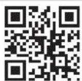
ACCESS MORE INFORMATION: By scanning the following QR code with your mobile phone camera you will access our website where you will find the necessary information.
IN CASE OF BREAKDOWN: You can contact our Technical Service department:
This equipment must be installed and configured by a qualified technician in accordance with the standards established by local health and safety regulations, such as low voltage electrotechnical regulations, technical building code and relevant local regulations.
Official technical service: 911 08 08 08
WARRANTY CONDITIONS
Electrical and Gas water heaters
It is essential to present the purchase invoice accompanied by this warranty certificate.
Covered Risks.
This appliance is guaranteed against any defect in operation, provided it is intended for domestic use, proceeding to repair it within the warranty period and only through the authorized SAT network.
Our Corberó appliances have the manufacturer's legal warranty that covers any breakdown or defect for 36 months, from its date of January 1, 2022. If necessary, we will take care of any possible incident as long as it is due to a defective component or manufacturing fault.
Warranty Exceptions.
- That the date of the certificate does not coincide with the sale date of the original invoice.
- Breakdowns caused by impact, fall or any other cause of force majeure.
- If the device has been manipulated by unauthorized personnel.
- Breakdowns produced or derived as a result of improper use, installation defects, for introducing modifications to the device that alter its operation.
- Start-up, maintenance, cleaning, components subject to wear, lamps, aesthetic parts, oxidations, plastics, rubber, casings and glass.
Electric water heater warranty.
3-year warranty including travel and labor costs corresponding to the repair of the product, and must have maintenance once every 12 months. Especially if you have installed a gas appliance, keep in mind as the owner of the installation, the obligation to carry out a complete review of the equipment (according to Royal Decree 238 / 2013, of April 5. RITE. IT3.
This equipment must be installed and configured by a qualified technician in accordance with the standards established by the local health and safety regulations, such as the low voltage electrotechnical regulation, the technical code of building and relevant local regulations.
For electric water heaters and boilers that include hot water storage tanks, for the Guarantee benefit to be applied, it is mandatory that the magnesium anode is operational and that it performs the protection function adequately. To do this, it is necessary that the anode be inspected for annual maintenance by the Official Service and renewed when necessary. This should be done more frequently in those areas with critical waters (CaCO3 content greater than 200 mg/L, that is, from 20°F hardness).
Tanks without the correct state of the protective anode do not have warranty coverage. Regardless of the type of tank or product, all heating or DHW overpressure valves must be channeled to avoid damage to the home due to water discharges. The product warranty does not cover damage caused by the failure to channel the water spilled through this valve.
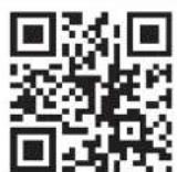
ACCESS MORE INFORMATION: By scanning the following QR code with your mobile phone camera you will access our website where you will find the necessary information.
IN CASE OF BREAKDOWN: You can contact our Technical Service department:
This equipment must be installed and configured by a qualified technician in accordance with the standards established by local health and safety regulations, such as low voltage electrotechnical regulations, technical building code and relevant local regulations.
Official technical service: 911 08 08 08
CONDIÇÕES DE GARANTIA
em Ar Condicionado
- Nota:
- Paso6: Conecte el cable
- SPLIT TYPE AIR CONDITIONER INSTRUCTION MANUAL
- CONTENTS
- SAFETY PRECAUTIONS
- SAFETY RULES AND RECOMMENDATIONS FOR THE INSTALLER
- SAFETY RULES AND PROHIBITIONS
- NAME OF PARTS
- Indoor Display
- REMOTE CONTROL
- Replacement of Batteries
- Note:
- COOLING MODE
- COOL
- FAN MODE (Not FAN button)
- FAN
- DRY MODE
- DRY
- AUTO MODE
- AUTO
- HEATING MODE
- HEAT
- ⚠ (For North American market)
- FAN SPEED function (FAN button)
- Child-Lock function
- TIMER function ---- TIMER ON SWING function
- TIMER function ---- TIMER OFF
- TURBO function
- TURBO
- MUTE function ECO function
- MUTE
- ECO
- SLEEP function
- SLEEP
- DISPLAY function (Indoor display)
- DISPLAY
- I SET function (Optional)
- OPERATION INSTRUCTIONS
- Characteristics of heating operation (applicable to Heating pump)
- Preheating:
- Defrosting:
- Emergency button:
- INSTRUCTION FOR SERVICING(R32)
- Information on servicing:
- Repairs to sealed components
- Repair to intrinsically safe components
- Cabling
- Detection of flammable refrigerants
- Leak detection methods
- Removal and evacuation
- Decommissioning
- Labeling
- Recovery
- INSTALLATION PRECAUTIONS(R32)
- Important Considerations
- The maximum charge and the required minimum floor area
- Installation Safety Principles
- Site Safety
- Operation Safety
- Installation Safety
- Please note that:
- INSTALLATION PRECAUTIONS
- INDOOR UNIT INSTALLATION
- Step1: Select Installation location
- Minimum Indoor Clearances
- Step2: Install Mounting Plate
- Step3: Drill Wall Hole
- Caution:
- Step4: Connecting Refrigerant Pipe
- Step5: Connect Drainage Hose
- Adjust the drainage hose(if applicable)
- Step6: Connect Wiring
- Step7: Wrap Piping and Cable
- Step8: Mount Indoor Unit
- Sometimes, if the refrigerant pips were already embedded in the wall, or if you want to connecting the pips and wires on the wall, do as below:
- OUTDOOR UNIT INSTALLATION
- Step2: Install Drainage Hose
- Step3: Fix Outdoor Unit
- Step4: Install Wiring
- Step5: Connecting Refrigerant Pipe
- Step6: Vacuum Pumping
- TEST OPERATION
- Inspections Before Test Run
- Test Run Instruction
- MAINTENANCE
- TROUBLESHOOTING
- ERROR CODE ON THE DISPLAY
- DISPOSAL GUIDELINE (European)
- Corberó
- Inicio de sesión
- Contraseña olvidada
- Add device (Agregar dispositivo)
- Gestión de cuenta
- Login
- Let's get start!
- FCC Caution (FCC ID: 2AJCLTWAC-TYWFS)
- Wi-Fi Module specification and basic information
- Minimum specifications on a Smart phone:
- Basic parameters for Wi-Fi module
- Wi-Fi module location and appearance in indoor unit
- For Android smart phone
- For IOS smart phone
- The first time the app is used, it will need activating.
- SmartLife-SmartHome
- Registration
- Login Login
- The first time the APP is used, Create family is needed:
- Forgot the password
- CF mode
- There are 2 methods to add the device.
- 2-AP mode
- Air conditioner control
- Control form1
- Control form1-Mode setting
- Control form1-Select fan speed
- Control form1-Function setting
- Control form1-Timer adding
- Control form1-Timer Management
- Control form2
- Control form2-Mode setting
- Control form2-Fan speed selection
- Control form2-Air Flow control
- Control form2-ECO function
- Control form2-Sleep function
- Control form2-Timer(on) setting
- Control form2-Timer(off) setting
- Control form2-Timer management
- Change the Timer setting:
- Enable or Disable the Timer:
- Delete the Timer:
- Control form2-More functions
- Device details and management
- How to share the devices to other accounts?
- Account management
- Home(Family) management
- Notice
- CERTIFICADO DE GARANTÍA
- Covered Risks.
- Warranty Exceptions
- Official Technical Service:
- 08 08 08
- CERTIFICADO DE GARANTIA
- Official technical service: 911 08 08 08
- WARRANTY CONDITIONS
- Warranty Exceptions.
- Electric water heater warranty.
- CONDIÇÕES DE GARANTIA
Brand : CORBERO
Model : CSP18GREGAL
Category : Air conditioner