
xMac Studio - External hard drive Sonnet - Free user manual and instructions
Find the device manual for free xMac Studio Sonnet in PDF.


| Product Type | Rackmount Enclosure for Mac Studio with Thunderbolt PCIe Expansion |
| Brand | Sonnet Technologies |
| Model | xMac Studio |
| Dimensions (W x H x D) | 19.00 x 5.22 x 16.47 inches (482.6 x 132.6 x 418.3 mm) |
| Weight | Approximately 12 lbs (5.4 kg) without modules |
| Power Input | 100-240V AC, 50/60Hz (via Echo Module power supply) |
| Compatible Computers | Mac Studio with M series processors, macOS 12.3+ |
| Expansion Module Options | Echo III (three PCIe slots) or Echo I (one PCIe slot) |
| PCIe Slot Specifications | Echo III: Slot 1 x8 (x8) PCIe 5.0, Slot 2 x16 (x8) PCIe 3.0, Slot 3 x8 (x4) PCIe 3.0; Echo I: x16 (x4) PCIe 3.0 |
| Thunderbolt Interface | Thunderbolt 3 (40Gbps) or Thunderbolt 4 cable; two ports on Echo III, one on Echo I |
| Front Panel Features | USB hub (passthrough), power switch, power indicator LED, Echo Module access |
| Accessory Space | Beneath computer for SSDs up to 3.2 x 0.7 inches (81 x 17.7 mm) with airflow cover plate |
| Cooling | Temperature-controlled fans in Echo Module; do not block vents |
| Rackmount Compatibility | Adjustable rails for depths 16-24 inches (41-61 cm) |
| Included Accessories | Rack ears, screws, power cord (with Echo Module), Thunderbolt cable, Thunderbolt retainer clip, self-adhesive magnets |
| Safety Compliance | FCC Part 15, RoHS compliant |
| Maintenance | Clean exterior with dry cloth; avoid liquids; do not block vents |
| Spare Parts and Repairability | Contact Sonnet Customer Service for support; no user-serviceable parts inside |
Frequently Asked Questions - xMac Studio Sonnet
User questions about xMac Studio Sonnet
0 question about this device. Answer the ones you know or ask your own.
Ask a new question about this device
Download the instructions for your External hard drive in PDF format for free! Find your manual xMac Studio - Sonnet and take your electronic device back in hand. On this page are published all the documents necessary for the use of your device. xMac Studio by Sonnet.
USER MANUAL xMac Studio Sonnet

ortNote: This document was up to date at the
time of printing. However, changes to the
hardware or software may have occurred since then. Please check the Sonnet website for the latest documentation.
- Go to https://www.sonnettech.com/support/kb/kb.php
- Navigate to and click the xMac Studio link.
- Click the Manual link.
- Click the xMac Studio User's Guide [English] link and then check the Document Version Information. If the version listed is later than this document (revision E), click the Download Now button for the latest version.

THUNDERBOLT.
PCI
EXPRESS®

Mac


RoHS COMPLIANT

Contents
1 Introduction and System Requirements 1
Introduction
Mac Compatibility
System Requirements
2 xMac Studio Description 2
Front Panel
Back Panel - xMac Studio / Echo III
Back Panel - xMac Studio / Echo I
Echo III Module Interior
Echo I Module Interior
Additional Package Contents
3 Computer Installation and Module Removal Steps 7
4 Echo III Module PCIe Card Installation Steps 9
5 Echo I Module PCIe Card Installation Steps 11
6 Echo Module Installation Steps 12
7 Accessory Installation Steps (Optional) 13
8 Final Assembly and Enclosure Installation Steps 15
9 Complete Setup and Configuration 17
10 Tips, General Information, and Known Issues 18
Tips, General Information
Known Issues
11 Precautions, FCC Compliance, and Support Information 19
Safety Precautions
FCC Compliance
Contacting Customer Service
Section 1 – Introduction and System Requirements
![19.00 [482.6] 5.22 [132.6]](/content/2026/05/901004/images/9ebdd368a04b1aa96f8cea739a8ae07ce2b96000c8637e50a78e3882c9e31f1c.jpg)
![16.47 [418.3]](/content/2026/05/901004/images/202b2f391c41e3ccf4bc509b26698cfd5183dca018cc1d7c48bb1372a32dbd66.jpg)

Introduction
Congratulations on your purchase! xMac Studio is a rackmount enclosure for Mac Studio™ computers and Sonnet Echo Thunderbolt expansion modules for PCIe cards. Through a module's PCIe slot(s), you may connect one or three non-GPU adapter cards to your Mac Studio to expand its capabilities and add connectivity beyond what's offered through its native ports.
System Requirements
While Echo modules require no drivers beyond those pre-installed in your computer's OS, many expansion cards you install do; Thunderbolt-compatible drivers to enable them to work properly through the Thunderbolt interface are required. More information on which cards are compatible with Echo I and Echo III Modules is available at: https://sonnettech.com/support/
Mac® Compatibility
• Mac Studio computers with PCIe cards that have M series processor-compatible drivers
•macOS* 12.3+
Section 2 - xMac Studio Description

Front Panel
1 - USB Hub
This connects via a passthrough cable to one of the computer's back-panel USB ports, supporting connection of keyboards, mice, thumb drives, and other USB devices. Note that the total number of USB devices you can connect to the hub may be limited by the width of the devices' USB connectors.
2 - Power Switch
This button activates the Mac Studio computer's power switch; an installed Echo Module's power supply turns on and off along with the computer.
3 - Echo Module
Depending on the xMac Studio model you purchased, there is either an 3-slot (Echo III Module) or 1-slot (Echo I Module) Thunderbolt to PCIe card expansion system, or an empty space for installing one of the modules. Note that you may remove and install the Echo Module without removing the rackmount enclosure's front panel; instructions follow.
4 - Power Indicator LED
In systems including an Echo Module, this lights when the Echo Module is powered, the Thunderbolt cable between the module and your computer is plugged in securely, and the computer powered on.
Section 2 - xMac Studio Description
Back Panel - xMac Studio / Echo III

Back Panel - xMac Studio / Echo I


ortNotes: The xMac Studio / No Module system is not shown here.
The Echo III Module includes two Thunderbolt ports and two threaded nuts for the included Thunderbolt connector retainer clip; the Echo I Module only has one each.
1 - Threaded Nut(s) for ThunderLok 5
Attach the included Thunderbolt connector retainer clip here.
2 - Thunderbolt Port(s)
Connect the included (or comparable) Thunderbolt 5 (40Gbps) cable, or any Thunderbolt 4 cable, between one of these ports and one of your computer's Thunderbolt ports.
The Echo III Module's second Thunderbolt port may be used to connect to another Thunderbolt peripheral device. We recommend that you connect displays and USB devices directly to your Mac Studio instead of the second Thunderbolt port.
5 - Power Input Socket
Connect the included AC power cord here.
4 - Accessory Space/Airflow Integrity Cover Plate
Remove this plate to insert your Thunderbolt or USB SSD (or other compact device) up to 3.2-inches (81 mm) wide by 0.7-inch (17.7 mm) tall, and then reinstall the plate to secure the device. Depending on its size, you may install more than one device. This plate must be reinstalled after removal to ensure the installed Mac Studio computer cools properly.

Support Note: You may install SSDs up to 0.9-inches
(23 mm) tall when inserted through the front of the
rackmount enclosure (with the front panel removed).
Section 2 - xMac Studio Description
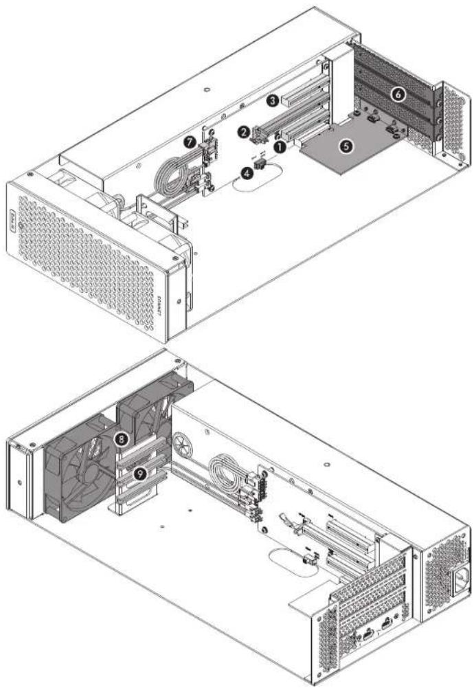
Echo III Module Interior
1 - Slot 1
This is an x8 mechanical (x8 electrical) PCIe 5.0 slot.* It is also compatible with PCIe 4.0, 2.0, and 1.1 cards.
2 - Slot 2
This is an x16 mechanical (x8 electrical) PCIe 3.0 slot.* It is also compatible with PCIe 4.0, 2.0, and 1.1 cards.
5 - Slot 5
This is an x8 mechanical (x4 electrical) PCIe 3.0 slot.* It is also compatible with PCIe 4.0, 2.0, and 1.1 cards.
4 - PCIe Gen 3/Gen 2 (HDX) Mode Switch
This switch enables the use of Avid Pro Tools | HDX PCIe cards in the Echo Module; instructions follow.
5 - Thunderbolt Interface Card
This card is installed in its own slot and may not be moved to another.
6 - PCIe Slot Access Covers
These cover openings when PCIe slots are unoccupied.
7 - 6-Pin Auxiliary Power Connector and Cable
Plugged into this connector is the auxiliary power cable for cards requiring extra power. When installing Avid Pro Tools | HDX PCIe cards, disconnect the supplied cable and connect an HDX card's custom power cable in its place.
8 - Temperature-Controlled Fans
These provide cooling for the installed PCIe cards and the module's supporting Thunderbolt and power circuitry. They operate at a whisper when the cards are running cool, and automatically speed up in steps as the temperature rises. To prevent overheating, do not block the fans or the vent holes on the module.
9 - PCIe Card Guides
When installing full-length cards, use these to support and secure the cards.
Section 2 - xMac Studio Description
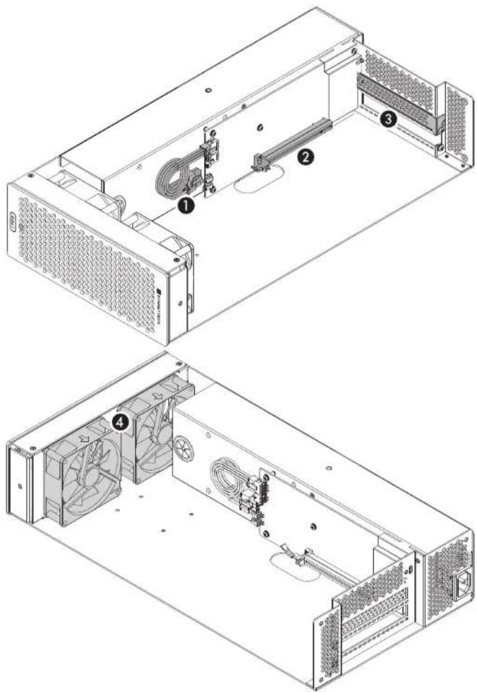
Echo I Module Interior
1 - Auxiliary Power Connectors and Cable
When auxiliary power is required, these connectors provide power to the installed card.
2 - PCIe Card Slot
This is an x16 mechanical (x4 electrical) PCIe 3.0 slot. It is also compatible with PCIe 4.0, 2.0, and 1.1 cards.
5 - PCIe Slot Access Cover
Remove this cover when installing a double-width card. If a single-width card is installed, leave this in place.
4 - Temperature-ControlledFans
These provide cooling for the installed card and the module's supporting Thunderbolt and power circuitry. They operate at a whisper when the cards are running cool, and automatically speed up in steps as the temperature rises. To prevent overheating, do not block the fans or the vent holes on the module.
Section 2 - xMac Studio Description
Additional Package Contents
Rackmount Rails
When installed on the enclosure's upper mounting pins, the rails support system installation in racks with mounting depths ranging from 16–20.25 inches. When installed on lower mounting pins, the rails support system installation in racks with mounting depths ranging from 19.75–24 inches.
Rack Ears and Mounting Screws
Attach the ears to the rackmount enclosure with the eight included screws (four screws each).
Power Cord
Included only with xMac Studio with an Echo Module, connect this between a power outlet and the power input socket on the Echo Module. Note that the power cord included with your product may appear different than the one pictured here, depending on where the product was purchased.
Thunderbolt 3 (40Gbps) Cable
Included only with xMac Studio with an Echo Module, connect this cable between a Thunderbolt port on the module and a Thunderbolt/USB4 port on your computer.
Thunderbolt 3 Connector Retainer Clip
Included only with xMac Studio with an Echo Module, this clip secures the Thunderbolt 3 connector plugged into one of the module's Thunderbolt ports to prevent accidental cable disconnection. This clip is compatible with Sonnet 0.5- and 0.7-meter Thunderbolt 3 cables.
Self-adhesive Magnets
The magnets may be cut to size and affixed to Thunderbolt or USB SSDs or other devices (except for spinning drives) installed in the enclosure's accessory space to secure them in place; instructions follow.


Section 3 – Computer Installation and Module Removal Steps

Support Note: If you only need to remove the Echo Module, you do not
have to remove the front panel from the rackmount enclosure. Simply
remove the three thumbscrews securing the module to the back of the enclosure, and then push the module out through the front.
- Remove the xMac Studio from its packaging, and then set it on a flat, level surface.
-
Remove the six thumbscrews securing the front panel to the rackmount enclosure, and then set aside the screws and front panel (Figure 1).
-
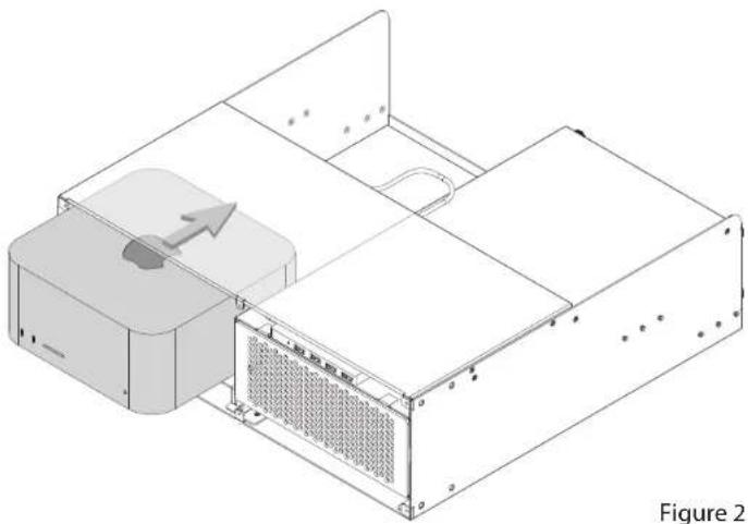
Remove your Mac Studio computer from its packaging, and then carefully insert it into the rackmount enclosure as shown. Push the computer in until it stops (Figure 2).

Figure 1
Section 3 – Computer Installation and Module Removal Steps
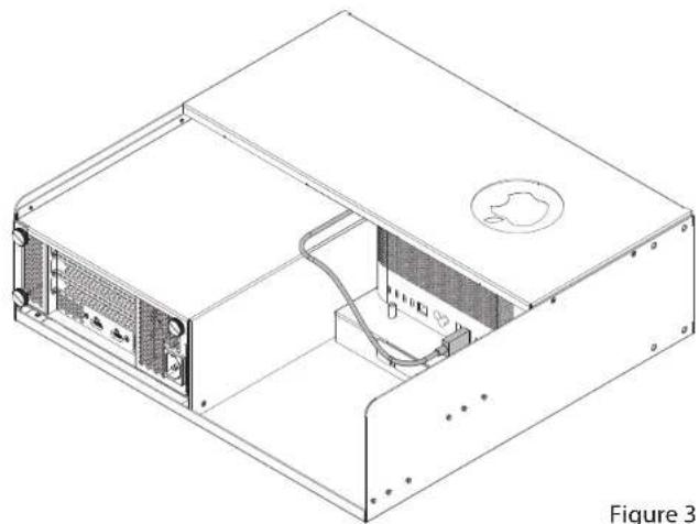
- Connect the USB hub's cable to a USB-A port on the Mac Studio (Figure 3).
- If you purchased an xMac Studio without an Echo Module, skip to the next page. Otherwise, remove and set aside the three thumbscrews securing the Echo Module to the rackmount enclosure (Figure 4).
- Push the Echo Module out through the front of the enclosure (Figure 4).

Section 4 – Echo III Module PCIe Card Installation Steps
This section covers the installation of PCIe cards into an Echo III Module. If you purchased an xMac Studio with an Echo I Module, skip to page 11.

Support Note: To avoid damaging components due to static electricity discharge, wear an antistatic wrist strap while working inside the Echo
Module.
- Remove and set aside the screw securing a PCIe slot access cover (Figure 5).
- Remove and set aside the loose PCIe slot access cover (Figure 5).
- If you are installing more than one card, repeat steps 1 and 2 as necessary with the remaining PCIe slot access covers.

WARNING: When handling computer products, take care to prevent components from being damaged by static electricity; avoid working sites. Handle expansion cards only by their edges and avoid touching or traces and component pins. Also, avoid touching the Echo III Module's boards and any of its components.
-
OPTIONAL STEP 1: If you are not installing a PCIe card which requires auxiliary power, skip to step 6. Otherwise, locate the auxiliary power cable (Figure 6).
-
When installing one or more Pro Tools | HDX PCIe cards, disconnect and set aside the power cable, replace it with the custom power cable included with an Avid card, and then move the loose connectors aside for later connection.
-
When installing cards other than the Pro Tools | HDX, remove the cable tie securing the power cable, and then move the loose connector aside for later connection.
-
OPTIONAL STEP 2: If you are installing one or more Avid Pro Tools | HDX cards, move the Gen 5/Gen 2 (HDX) switch (Figure 6) to the Gen 2 (HDX) position to enable compatibility. Otherwise, the card(s) will not work in the Echo Module.

Figure 5
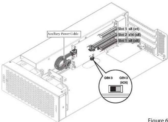
Figure 6
Section 4 – Echo III Module PCIe Card Installation Steps
- Remove a PCIe card from its packaging, handling the card by its edges and without touching any components or gold connector pins.

Support Note: If you are installing an x8 PCIe 1.1 card, installing it into slot 3 may result in reduced performance. We recommend you install it
Into either slot 1 or 2 for best performance.
- Line up the card's connector with the slot, and then gently but firmly press the card straight into the slot; do not rock the card or force the card into the slot. If you encounter excessive resistance, check the card's connector and the slot for damage, and then try inserting the card again (Figure 7).
- Repeat steps 6 and 7 as necessary with any remaining cards.
- If you installed a card which requires auxiliary power, connect the auxiliary power connector to it now.
- If there are any unoccupied slots, install the PCIe slot access covers you removed previously, and then secure the cards and slot covers using the previously-removed screws (Figure 7).
- Skip to page 12.
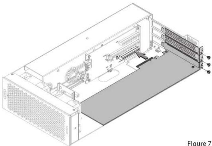
Figure 7
Section 5 – Echo I Module PCIe Card Installation Steps

Support Note: To avoid damaging components due to static electricity discharge, wear an antistatic wrist strap while working inside the Echo I Module.
- Remove and set aside the screw next to the PCIe slot access cover (Figure 8).
- If you are installing a double-width card, or an additional daughter card, remove and set aside the screw securing the PCIe slot access cover, and then remove and set aside the cover (Figure 8).
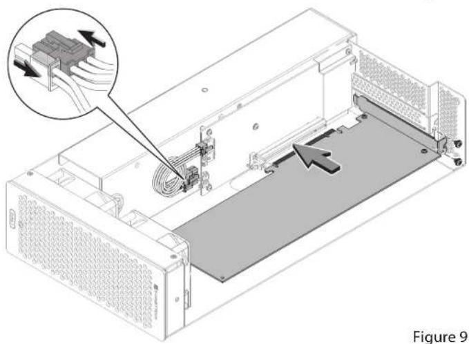
- OPTIONAL STEP: If you are not installing a PCIe card which requires auxiliary power, go to step 4. Otherwise, locate the auxiliary power cable (Figure 9).
- When installing an Avid Pro Tools | HDX PCIe card, disconnect the power cable from the module and set it aside, replace it with the custom power cable included with the Avid card, and then move the loose connectors aside for later connection.
- When installing a card other than the Pro Tools | HDX, remove the cable tie securing the power cable, and then move the loose connector aside for later connection.

WARNING: When handling computer products, take care to prevent components from being damaged by static electricity; avoid working in carpeted areas. Handle ion cards only by their edges and avoid touching connector traces and component so, avoid touching the Echo I Module's circuit boards and any of its components.
- Remove the PCIe card you're installing from its packaging, handling the card by its edges and without touching any components or gold connector pins.
- Line up the card's connector with the slot, and then gently but firmly press the card straight into the slot; do not rock the card or force the card into the slot. If you encounter excessive resistance, check the card's connector and the slot for damage, and then try inserting the card again (Figure 9).
- Secure the card using the screw(s) you removed previously; do not overtighten the screw(s) (Figure 9).

Support Note: The Echo I Module includes an "8-pin" auxiliary power connector, comprised of a 6-pin plus 2-pin connector pair. To create an 8-pin connector, slide pin and 2-pin connectors together as shown (Figure 9).
- If required, connect the auxiliary power connector(s) to the installed card; make sure the connectors are plugged in securely. Proceed to the next page.
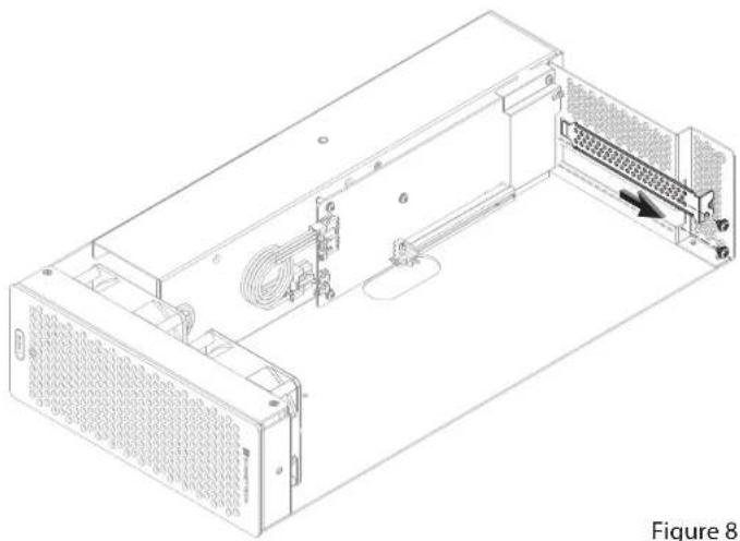
Figure 8
Section 6 – Echo Module Installation Steps
- Insert the Echo Module into rackmount enclosure (Figure 10).
2 Using the three thumbscrews you removed previously, secure the Echo Module to the enclosure; do not overighten the screws (Figure 10).

Support Note: Sonnet's ThunderLok™ 3 Thunderbolt connector retainer clip secures the included Thunderbolt 3 cable to the module to prevent accidental hects. This clip is compatible with Sonnet 0.5- and 0.7-meter Thunderbolt 3 cables.
To attach the clip to the cable, remove both items from their packaging, and then insert the connector into the connector clip as shown (Figure 11). Note that the connector will pass all the way through the clip; when you connect the cable to the module, the clip will secure the connector.
- Connect the included (or comparable) Thunderbolt 5 (40Gbps) cable, or any Thunderbolt 4 cable, between the Thunderbolt port on the Echo Module and a Thunderbolt port on the back of your computer (Figure 11). Secure the retainer clip to the module if you attached it.

Figure 10

Section 7 – Accessory Installation Steps (Optional)
The following two pages explain how to utilize the space beneath the computer to install Thunderbolt or USB SSDs or other accessories. If you are not going to install an accessory, skip to page 15.
- Using a Phillips screwdriver, remove the screws securing the accessory space/airflow integrity cover plate to the enclosure, and then set aside the screws and plates (Figure 12).

Figure 12

Support Notes: If the rack or case the xMac Studio is installed in will be moved around, you should secure any drives or other devices you install the enclosure. If you are installing SSDs or some other device, use the included adhesive magnets to secure them. Do not use the supplied magnets to secure driving drives.
If necessary, the magnets may be cut to size to fit the devices they are attached to.
- OPTIONAL STEP: If you are installing something other a spinning drive (and you need to secure it), remove the protective backing from one of the supplied magnets and then apply it to the bottom of the device (Figure 13).

Figure 13
Section 7 – Accessory Installation Steps (Optional)
- Insert the device into the space beneath the computer, placing it far enough back so that the device's cables may be routed through the accessory space cover plate (Figure 14).
-
Connect the device to the computer (Figure 14). If you are installing additional devices in the space, do so now.
-
Using the previously removed screws, secure the accessory space/airflow integrity cover plate to the enclosure (Figure 15).

Support Note: It is very important to reinstall the accessory space/airflow integrity cover plate in order to prevent the Mac Studio from g in warm air through the accessory space opening.
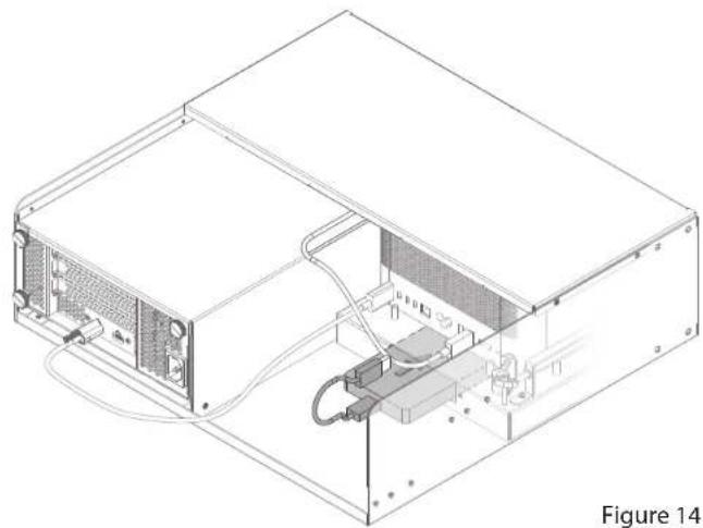
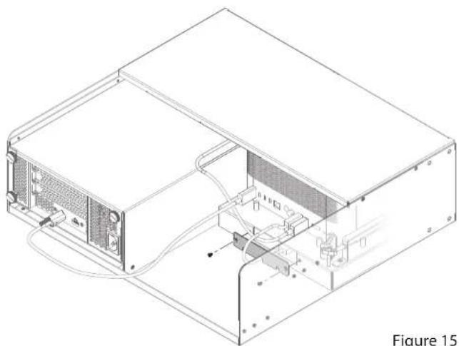
Figure 15
Section 8 – Final Assembly and Enclosure Installation Steps
-
Using the six thumbscrews you removed previously, secure the front panel to the enclosure; do not overtighten the screws (Figure 16).
-
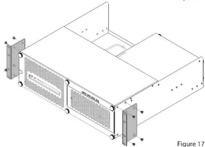
Using the eight supplied screws, secure the rack ears to the rackmount enclosure (Figure 17).

Section 8 – Final Assembly and Enclosure Installation Steps
- Attach the rackmount extension rails on the rackmount enclosure and adjust them as necessary (Figure 18).
- Install the assembled xMac Studio into its rack or case.
- Connect interface and power cables between devices, PCIe cards, and the computer as necessary.
- Connect the power cord included with the Echo Module between a wall outlet or power strip and the module's power socket. Note that the Echo Module's power indicator will not light until the computer is powered on.

Support Note: If you haven't set up your Mac Studio, you will need to connect a monitor, keyboard, and mouse to complete those steps.
- Proceed to the next page.

Figure 18
Section 9 – Complete Setup and Configuration
ECHO MODULE SETUP AND CONFIGURATION STEPS
This page instructs you how to verify the Echo Module and installed cards are recognized by the computer.
A - Confirm the Echo Module is Recognized
- With the Echo Module powered and connected to the computer, turn on the computer.
- Press and hold down the Option key, and then from the Apple menu, select System Information; a System Information window will open.
- In the System Information window, click Thunderbolt/USB4 under the Hardware header in the left column (Figure 19). In the top right column under the Thunderbolt/USB4 Device Tree header, you will see Thunderbolt/USB4 Bus, and then "DuoModo Echo III Module" or "DuoModo eGPU Module (for the Echo I Module).

Support Note: If "DuoModo Echo III Module" or "DuoModo eGPU Module" is not listed, disconnect and reconnect the Thunderbolt between the computer and module. Note that it is not necessary to shut the computer before disconnecting and reconnecting the cable.
B – Confirm the Installed Cards are Recognized
- In the System Information window click PCI under the Hardware header in the left column (Figure 20).
- At the top of the right column, installed cards (and/or card controllers) are listed (if not, you may need to install drivers before the cards are recognized). Click one of the cards; you should see "Yes" next to Driver Installed and Tunnel Compatible, otherwise the card or driver may not be Thunderbolt- or M1 processor-compatible (Figure 20).

Support Note: While Echo Modules don't require drivers beyond those pre-installed in your computer's OS, installed cards require erbolt-compatible drivers to enable their use.
C - Install Card Drivers (If Necessary)
- Launch a web browser, and then go to your card manufacturer's website. Download and install the latest drivers according to the manufacturer's directions.
- Restart your computer; your Echo Module is ready to use!
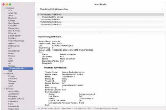
Figure 19

Figure 20
Section 10 – Tips, General Information, and Known Issues
TIPS, GENERAL INFORMATION
Keeping the Cards Cool
With its optimized airflow design and temperature-controlled fan providing cooling at all times, an Echo Module provides adequate cooling for the installed cards. Do not operate the Echo Module outside of its enclosure, and do not block any of the vents! Otherwise, the installed cards and Echo Module's components may overheat.
Hot Plugging the Echo Module
When certified Thunderbolt-compatible cards (used with Thunderbolt-compatible drivers) are installed, you may connect and disconnect the module while the computer is on. Of course, if you have anything connected to the cards, such as storage devices, cameras, etc., follow proper procedures for disconnecting those devices before unplugging the Echo Module.
There's No Need to Unplug the Power Cable
Because an Echo Module automatically powers on and off with the computer to which it's connected, there's no power switch, nor is there any need to disconnect the power cable under normal use.
Power Indicator LED Operation
An Echo module automatically powers on and off with the computer to which it's connected, and its power indicator only lights when the computer is on and turns off when the computer is sleeping or powered off.
Connecting Additional Thunderbolt Peripherals
Because the Mac Studio includes a separate Thunderbolt controller for each Thunderbolt port and provides full PCIe bandwidth to each, we recommend you use the computer's Thunderbolt ports first to connect additional peripherals.
The Echo III Module includes two Thunderbolt ports; one is reserved for connection to your computer, while the second supports daisy-chaining of up to five additional Thunderbolt peripheral devices; due to an operational issue with the Mac Studio, connecting displays to the Echo III Module is not recommended.
Using Expansion Cards Without Installing Drivers Some Thunderbolt-compatible expansion cards, like Sonnet's Allegro™ Pro USB 3.2 PCIe cards, use inbox (built into the operating system) drivers, and are ready to use out of the box.
Replacing a PCIe Card After Initial Installation Shut down the computer, and then disconnect the power cord and Thunderbolt cable from the Echo Module before opening the chassis and replacing the card; PCIe cards are not hot-pluggable!
Echo III Module Provides Downstream Power
The Echo III Module can provide up to 15 watts to bus-powered Thunderbolt peripheral devices, enabling them to operate without connecting an additional power adapter.
How to Identify Thunderbolt 3 (40Gbps) Cables Look for the Thunderbolt icon (✗) AND the number 3 on the connector housings to identify these cables. Aside from Thunderbolt cables from Apple, USB-C cables with connectors that only have the Thunderbolt icon without the number 5 may only support 20Gbps speeds, and are not recommended for use with the Echo Module. Cables marked with a generic USB icon (✗) are NOT compatible for connecting the Echo Module to the computer.
Thunderbolt 4 Cable Compatibility
You may use Thunderbolt 4 cables with Thunderbolt 4 or Thunderbolt 5 computers and peripherals without any compromise in performance or functionality.
Not All Mac-Compatible Cards Work With Mac Studio
While this product is compatible with M series processors, not all PCIe cards that work with Intel-based Macs have M series processor-compatible drivers. We recommend that you contact your PCIe card's manufacturer to verify that the existing drivers support M series Macs.
KNOWN ISSUES
Not all PCIe Cards Will Perform at 100%
Thunderbolt 5 technology's PCIe bandwidth is limited to 2,800 MB/s. While most PCIe cards will operate at full performance, some may not because they require more bandwidth than Thunderbolt 3 can provide.
Not All Thunderbolt Cables Deliver Full Performance Full performance from the Echo Module requires the use of the included (or comparable) Thunderbolt 3 (40Gbps) cable, or any Thunderbolt 4 cable. When shopping for a Thunderbolt 3 cable, please be aware that some support only lower data transfer speeds (20Gbps).
Operating System (OS) Updates May Break Compatibility Specific device drivers that work under one OS version may not work under a later version. Before updating your computer to the latest OS, we recommend that you contact your PCIe card's manufacturer to verify that the existing drivers work. Note that other computer software updates may also break compatibility.
Section 11 – Precautions, FCC Compliance, and Support Information
SAFETY PRECAUTIONS
Please read this section carefully before proceeding. These precautions explain the correct and safe use of this device, thereby helping to prevent injury to you or others, and also help you to minimize the risk of damaging the device.
- Do not attempt to modify the enclosure. If this device appears to be malfunctioning, contact your reseller or local distributor.
- Do not drop the chassis; dropping or mishandling chassis may result in a malfunction leaving the product inoperable.
- Do not insert foreign objects inside the slots.
- Do not expose the device to rain, use it near water or containers that contain liquids which might spill into any openings, or in damp or wet conditions.
- If unusual smells, sounds, or smoke come from the device, or if liquids enter it, unplug it from the electrical outlet immediately.
- Follow the instructions in this manual carefully; contact your reseller or local distributor for additional advice not covered in this User's Guide.
FCC Compliance
xMac Studio complies with Part 15 of the FCC Rules. Operation is subject to the following two conditions: This device may not cause harmful interference, AND this device must accept any interference received, including interference that may cause undesired operation.
Contacting Customer Service
The Sonnet Web site located at www.sonnettech.com has the most current support information and technical updates. Before contacting Customer Service, please check our Web site for the latest updates and online support files, and check this Quick Start Guide for helpful information. Email support requests generally receive the fastest responses, and are usually processed within a 24-hour period during normal business hours, excluding holidays. When you contact Customer Service, have the following information available so the customer service staff can better assist you:
- Product name
- Computer model
• PCIe card model(s) - Operating system version
- A macOS System Report, along with a description of the issue(s) you are encountering with your device
If further assistance is needed, please contact Sonnet Customer Service at:
E-mail: support@sonnettech.com
Tel: 1-949-472-2772
(Monday–Friday, 9 a.m.–5 p.m. Pacific Time, excluding holidays)
Japan Customers
Contact Sonnet Customer Service Japan at:
E-mail: jp.support@sonnettech.com

SONNETTECH
©2023 Sonnet Technologies, Inc. All rights reserved. Sonnet, SONNETTECH, the Sonnetech logoype, Allegro, and Echo are trademarks of Sonnet Technologies, Inc. Mac, the Mac logo, Mac Studio, and macOS are trademarks of Apple Inc., registered in the United States and other countries. Thunderbolt and the Thunderbolt logo are trademarks of Intel Corporation in the U.S. and/or other countries. Other product names are trademarks of their respective owners. Product specifications subject to change without notice. UG-XMAC-STD-E-E-072723

- CONTENTS
- 1 INTRODUCTION AND SYSTEM REQUIREMENTS 1
- 2 XMAC STUDIO DESCRIPTION 2
- 3 COMPUTER INSTALLATION AND MODULE REMOVAL STEPS 7
- 10 TIPS, GENERAL INFORMATION, AND KNOWN ISSUES 18
- 11 PRECAUTIONS, FCC COMPLIANCE, AND SUPPORT INFORMATION 19
- INTRODUCTION
- SYSTEM REQUIREMENTS
- MAC® COMPATIBILITY
- FRONT PANEL
- USB HUB
- POWER SWITCH
- ECHO MODULE
- POWER INDICATOR LED
- SECTION 2 - XMAC STUDIO DESCRIPTION
- THREADED NUT(S) FOR THUNDERLOK 5
- THUNDERBOLT PORT(S)
- POWER INPUT SOCKET
- ACCESSORY SPACE/AIRFLOW INTEGRITY COVER PLATE
- ECHO III MODULE INTERIOR
- ECHO I MODULE INTERIOR
- RACKMOUNT RAILS
- RACK EARS AND MOUNTING SCREWS
- POWER CORD
- THUNDERBOLT 3 (40GBPS) CABLE
- THUNDERBOLT 3 CONNECTOR RETAINER CLIP
- SELF-ADHESIVE MAGNETS
- SECTION 3 – COMPUTER INSTALLATION AND MODULE REMOVAL STEPS
- SECTION 4 – ECHO III MODULE PCIE CARD INSTALLATION STEPS
- SECTION 5 – ECHO I MODULE PCIE CARD INSTALLATION STEPS
- SECTION 6 – ECHO MODULE INSTALLATION STEPS
- SECTION 7 – ACCESSORY INSTALLATION STEPS (OPTIONAL)
- SECTION 8 – FINAL ASSEMBLY AND ENCLOSURE INSTALLATION STEPS
- SECTION 9 – COMPLETE SETUP AND CONFIGURATION
- ECHO MODULE SETUP AND CONFIGURATION STEPS
- A - CONFIRM THE ECHO MODULE IS RECOGNIZED
- B – CONFIRM THE INSTALLED CARDS ARE RECOGNIZED
- C - INSTALL CARD DRIVERS (IF NECESSARY)
- SECTION 10 – TIPS, GENERAL INFORMATION, AND KNOWN ISSUES
- TIPS, GENERAL INFORMATION
- KNOWN ISSUES
- SECTION 11 – PRECAUTIONS, FCC COMPLIANCE, AND SUPPORT INFORMATION
- SAFETY PRECAUTIONS
- FCC COMPLIANCE
- CONTACTING CUSTOMER SERVICE
- SONNETTECH
Brand : Sonnet
Model : xMac Studio
Category : External hard drive