MGSD-10080F - Switch Planet - Free user manual and instructions
Find the device manual for free MGSD-10080F Planet in PDF.


| Product Type | Managed Metro Ethernet Switch |
| Model Number | MGSD-10080F |
| Dimensions (W x D x H) | 330 x 155 x 43.5 mm (1U) |
| Weight | 1661 g |
| Power Input | AC 100-240V, 50/60Hz; DC 36-60V |
| Power Consumption | Max 11.2W (AC), 10.8W (DC) |
| Ports | 6 x 100/1000BASE-X SFP, 2 x 100/1000/2500BASE-X SFP, 2 x 10/100/1000BASE-T RJ45 |
| Switching Capacity | 26 Gbps (non-blocking) |
| Packet Throughput | 19.3 Mpps @ 64 bytes |
| MAC Address Table | 8K entries |
| VLAN Support | Up to 4K VLAN groups, IEEE 802.1Q, Q-in-Q, Private VLAN |
| Redundant Power Support | Active-active dual DC inputs + AC input |
| Digital Input/Output | 2 DI, 2 DO (open collector to 24V DC) |
| Operating Temperature | -10 to 60°C (DC input), 0 to 50°C (AC input) |
| Humidity (non-condensing) | 5% to 95% |
| Cooling | Fanless design |
| Security Features | 802.1x port authentication, ACL, DHCP Snooping, IP Source Guard, ARP Inspection, SSHv2, TLSv1.2, SNMPv3 |
| Management Interfaces | Web, CLI (console/Telnet), SNMP v1/v2c/v3, Smart Discovery Utility |
| Standards Compliance | FCC Part 15 Class A, CE, IEEE 802.3/802.3u/802.3ab/802.3z/802.3bz, IEEE 802.1D/w/s, IEEE 802.1Q/ad, IEEE 802.1X, ITU-T G.8032 |
| Package Contents | Switch, Quick Installation Guide, RJ45 to RS232 console cable, rubber feet, rack-mount brackets with screws, power cord, dust caps |
| Spare Parts / Repairability | No user-serviceable parts; contact PLANET support for repairs |
Frequently Asked Questions - MGSD-10080F Planet
User questions about MGSD-10080F Planet
0 question about this device. Answer the ones you know or ask your own.
Ask a new question about this device
Download the instructions for your Switch in PDF format for free! Find your manual MGSD-10080F - Planet and take your electronic device back in hand. On this page are published all the documents necessary for the use of your device. MGSD-10080F by Planet.
USER MANUAL MGSD-10080F Planet
natural_image
Blue network switch device with visible ports, connectors, and network ports (no readable text or symbols)10-Port Gigabit
Managed Metro Ethernet Switch
MGSD-10080F
natural_image
Man in white shirt and tie using laptop in server rack (no visible text or symbols)Trademarks
Copyright © PLANET Technology Corp. 2021.
Contents are subject to revision without prior notice.
PLANET is a registered trademark of PLANET Technology Corp. All other trademarks belong to their respective owners.
Disclaimer
PLANET Technology does not warrant that the hardware will work properly in all environments and applications, and makes no warranty and representation, either implied or expressed, with respect to the quality, performance, merchantability, or fitness for a particular purpose. PLANET has made every effort to ensure that this User's Manual is accurate; PLANET disclaims liability for any inaccuracies or omissions that may have occurred.
Information in this User's Manual is subject to change without notice and does not represent a commitment on the part of PLANET. PLANET assumes no responsibility for any inaccuracies that may be contained in this User's Manual. PLANET makes no commitment to update or keep current the information in this User's Manual, and reserves the right to make improvements to this User's Manual and/or to the products described in this User's Manual, at any time without notice.
If you find information in this manual that is incorrect, misleading, or incomplete, we would appreciate your comments and suggestions.
FCC Warning
This equipment has been tested and found to comply with the limits for a Class A digital device, pursuant to Part 15 of the FCC Rules. These limits are designed to provide reasonable protection against harmful interference when the equipment is operated in a commercial environment. This equipment generates, uses, and can radiate radio frequency energy and, if not installed and used in accordance with the Instruction manual, may cause harmful interference to radio communications. Operation of this equipment in a residential area is likely to cause harmful interference in which case the user will be required to correct the interference at his own expense.
CE Mark Warning
This device is compliant with Class A of CISPR 32. In a residential environment this equipment may cause radio interference.
Energy Saving Note of the Device
This power required device does not support Standby mode operation. For energy savings, please remove the power cable to disconnect the device from the power circuit. Without removing the power cable, the device will still consume power from the power source. In view of Saving the Energy and reducing the unnecessary power consumption, it is strongly suggested to remove the power cable from the device if this device is not intended to be active.
WEEE Warning
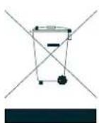
To avoid the potential effects on the environment and human health as a result of the presence of hazardous substances in electrical and electronic equipment, end users of electrical and electronic equipment should understand the meaning of the crossed-out wheeled bin symbol. Do not dispose of WEEE as unsorted municipal waste and have to collect such WEEE separately.
Revision
User's Manual of PLANET L2+ Metro Ethernet Switch
FOR MODEL: MGSD-10080F
REVISION:2.0 (November, 2021)
Part No: EM-MGSD-10080F_v2.0
TABLE OF CONTENTS
1. INTRODUCTION .... 10
1.1 Packet Contents....10
1.2 Product Description .... 11
1.3 How to Use This Manual .... 16
1.4 Product Features .... 17
1.5 Product Specifications....20
2. INSTALLATION 24
2.1 Hardware Description....24
2.1.1 Switch Front Panel....24
2.1.2 Wiring the AC Power Input 28
2.1.3 Wiring the DC Power Input....29
2.1.4 Wiring the Fault Alarm Contact....30
2.1.5 Wiring the Digital Input/Output ....30
2.2 Installing the Managed Metro Switch....33
2.2.1 Desktop Installation....33
2.2.2 Rack Mounting ....34
2.3 Cabling....35
2.3.1 Installing the SFP Transceiver ....36
2.3.2 Removing the SFP Transceiver....38
3. SWITCH MANAGEMENT .... 39
3.1 Requirements....39
3.2 Management Access Overview....40
3.3 CLI Mode Management....41
3.4 Web Management ....43
3.5 SNMP-based Network Management ....44
3.6 PLANET Smart Discovery Utility....44
4. WEB CONFIGURATION.... 46
4.1 Main Web page....49
4.2 System 51
4.2.1 Management ....52
4.2.1.1 System Information....52
4.2.1.2 IP Configuration....53
4.2.1.3 IP Status ....56
4.2.1.4 ARP Table....57
4.2.1.5 Users Configuration....58
4.2.1.6 Privilege Levels 61
4.2.1.7 NTP Configuration 63
4.2.1.7.1 System Time Correction Manually....64
4.2.1.8 Time Configuration 65
4.2.1.9 UPnP 67
4.2.1.14 Detailed Log 75
4.2.1.15 Remote Syslog 76
4.2.1.16 SMTP Configuration 77
4.2.1.17 Fault Alarm ....78
4.2.1.18 Digital Input/Output....79
4.2.2 Simple Network Management Protocol....82
4.2.2.1 SNMP Overview 82
4.2.2.2 SNMP System Configuration....83
4.2.2.3 SNMP System Information 84
4.2.2.4 SNMP Trap Configuration....85
4.2.2.5 SNMP Trap Source Configuration....87
4.2.2.6 SNMPv3 Communities....89
4.2.2.7 SNMPv3 Users 90
4.2.2.8 SNMPv3 Groups....92
4.2.2.9 SNMPv3 Views....93
4.2.2.10 SNMPv3 Access....94
4.2.3 RMON 95
4.2.3.1 RMON Alarm Configuration....95
4.2.3.2 RMON Alarm Status....97
4.2.3.3 RMON Event Configuration....98
4.2.3.4 RMON Event Status....99
4.2.3.5 RMON History Configuration....100
4.2.3.6 RMON History Status....101
4.2.3.7 RMON Statistics Configuration....102
4.2.3.8 RMON Statistics Status....103
4.2.4 DHCP server ....105
4.2.4.1 DHCP Server Mode Configuration....105
4.2.4.2 DHCP Server excluded IP Configuration....107
4.2.4.3 DHCP Server pool Configuration....108
4.2.4.4 DHCP Server Statistics....109
4.2.4.5 DHCP Server Binding IP Configuration 111
4.2.4.6 DHCP Server Declined IP 112
4.2.4.7 DHCP Detail Statistics 112
4.2.5 Remote Management....114
4.3 Switching....116
4.3.1 Port Management....116
4.3.1.1 Port Configuration....116
4.3.1.2 Port Statistics Overview 118
4.3.1.3 Port Statistics Detail....119
4.3.1.4 SFP Module Information....121
4.3.1.5 Port Mirror....123
4.3.1.6 Name Map....126
4.3.2 Link Aggregation....127
4.3.2.1 Common Aggregation Configuration....129
4.3.2.2 Static Aggregation Group Configuration....130
4.3.2.3 Static Aggregation Status....131
4.3.2.4 LACP Configuration....132
4.3.2.5 LACP System Status ....134
4.3.2.6 LACP Internal Status ....135
4.3.2.7 LACP Neighbor Port Status ....136
4.3.2.8 LACP Port Statistics....137
4.3.3 VLAN 138
4.3.3.1 VLAN Overview 138
4.3.3.2 IEEE 802.1Q VLAN 139
4.3.3.3 VLAN Port Configuration 144
4.3.3.4 VLAN Membership Status....149
4.3.3.5 VLAN Port Status....150
4.3.3.6 Private VLAN....152
4.3.3.7 Port Isolation....154
4.3.3.8 VLAN setting example:....156
4.3.3.9 MAC-based VLAN 162
4.3.3.10 IP Subnet-based VLAN Membership Configuration....163
4.3.3.11 Protocol-based VLAN 164
4.3.3.12 Protocol-based VLAN Membership 165
4.3.2.13 VLAN Translation....167
4.3.4 Spanning Tree Protocol....171
4.3.4.1 Theory 171
4.3.4.2 STP System Configuration ....177
4.3.4.3 Bridge Status....180
4.3.4.4 CIST Port Configuration....181
4.3.4.5 MSTI Priorities....184
4.3.4.6 MSTI Configuration....185
4.3.4.7 MSTI Ports Configuration ....186
4.3.4.8 Port Status....188
4.3.4.9 Port Statistics....189
4.3.5 Multicast....190
4.3.5.1 IGMP Snooping ....190
4.3.5.2 Profile Table....194
4.3.5.3 Address Entry 195
4.3.5.4 IGMP Snooping Configuration....196
4.3.5.5 IGMP Snooping VLAN Configuration....198
4.3.5.6 IGMP Snooping Port Group Filtering....200
4.3.5.7 IGMP Snooping Status ....201
4.3.5.8 IGMP Groups Information....202
4.3.5.9 IGMPv3 Information....203
4.3.6 MLD Snooping....204
4.3.6.1 MLD Snooping Configuration....204
4.3.6.2 MLD Snooping VLAN Configuration 205
4.3.6.3 MLD Snooping Port Group Filtering....207
4.3.6.4 MLD Snooping Status....208
4.3.6.5 MLD Groups Information ....209
4.3.6.6 MLDv2 Information....210
4.3.7 MVR (Multicast VLAN Registration)....212
4.3.7.1 MVR Configuration 213
4.3.7.2 MVR Status....215
4.3.7.3 MVR Groups Information....216
4.3.7.4 MVR SFM Information....217
4.3.8 LLDP 218
4.3.8.1 Link Layer Discovery Protocol ....218
4.3.8.2 LLDP Configuration 218
4.3.8.3 LLDP Neighbors 221
4.3.8.4 LLDP-MED Configuration 222
4.3.8.5 LLDP-MED Neighbors 229
4.3.8.6 Port Statistics....233
4.3.9 MAC Address Table....235
4.3.9.1 MAC Table Configuration....235
4.3.9.2 MAC Address Table Status....237
4.3.10 Loop Protection....239
4.3.10.1 Configuration....239
4.3.10.2 Loop Protection Status....240
4.3.11 UDLD 241
4.3.11.1 UDLD Port Configuration....241
4.3.11.2 UDLD Status....242
4.3.12 GVRP 244
4.3.12.1 GVRP Configuration 245
4.3.12.2 GVRP Port Configuration....246
4.3.13 PTP 247
4.3.13.1 PTP Configuration 248
4.3.14 Link OAM 256
4.3.14.1 Statistics 256
4.3.14.2 Port Status....258
4.3.14.3 Event Status 260
4.3.14.4 Port Settings....262
4.3.14.5 Event Settings 264
4.3.14.6 MIB Retrieval....265
4.3.14.7 Link-OAM Example....266
4.4 Quality of Service ....267
4.4.1 General....267
4.4.1.1 QoS Port Classification....268
4.4.1.2 Queue Policing ....270
4.4.1.3 Port Tag Remarking....271
4.4.1.4 Statistics 272
4.4.2 Bandwidth Control....273
4.4.2.1 Port Policing 273
4.4.2.2 Port Schedule 274
4.4.2.3 Port Shaping....276
4.4.3 Storm Control....278
4.4.3.1 Storm Policing Configuration 278
4.4.4 Differentiated Service 279
4.4.4.1 Port DSCP 279
4.4.4.2 DSCP-based QoS....281
4.4.4.3 DSCP Translation....282
4.4.4.4 DSCP Classification....283
4.4.5 QCL....284
4.4.5.1 QoS Control List....284
4.4.5.2 QoS Control Entry Configuration 286
4.4.5.3 QCL Status 288
4.4.5.4 Voice VLAN Configuration....290
4.4.5.5 Voice VLAN OUI Table....292
4.5 Security....293
4.5.1 Access Security....293
4.5.1.1 Access Management 293
4.5.1.2 Access Management Statistics....294
4.5.1.3 SSH....295
4.5.1.4 HTTPS 296
4.5.2 AAA 298
4.5.2.1 Authentication Configuration....303
4.5.2.2 RADIUS....305
4.5.2.3 TACACS+....307
4.5.2.4 RADIUS Overview 309
4.5.2.5 RADIUS Details 310
4.5.3 Port Authentication....317
4.5.3.1 Network Access Server Configuration....317
4.5.3.2 Network Access Overview 321
4.5.3.3 Network Access Statistics....322
4.5.4 Port Security....327
4.5.4.1 Port Limit Control....327
4.5.4.2 Port Security Status....330
4.5.4.3 Port Security Detail....332
4.5.5 Access Control Lists....333
4.5.5.1 Access Control List Status 333
4.5.5.2 Access Control List Configuration....335
4.5.5.3 ACE Configuration....337
4.5.5.4 ACL Ports Configuration 347
4.5.5.5 ACL Rate Limiters....349
4.5.6 DHCP Snooping....350
4.5.6.1 DHCP Snooping Configuration....351
4.5.6.2 Snooping Table 352
4.5.7 IP Source Guard 353
4.5.7.1 IP Source Guard Configuration....353
4.5.7.2 Static IP Source Guard Table....354
4.5.7.3 Dynamic IP Source Guard Table....355
4.5.8 ARP Inspection....356
4.5.8.1 ARP Inspection....356
4.5.8.2 ARP Inspection Static Table....357
4.5.8.3 Dynamic ARP Inspection Table....358
4.6 Ring 360
4.6.1 ERPS Ring 360
4.6.1.1 MEP Configuration....361
4.6.1.2 Detailed MEP Configuration ....363
4.6.1.3 Ethernet Ring Protocol Switch....368
4.6.1.4 Ethernet Ring Protocol Switch Configuration....370
4.6.1.5 Ethernet Ring Protocol Switch....373
4.6.1.6 Ring Wizard Example 374
4.7 Maintenance 377
4.7.1 Switch Maintenance....377
4.7.1.1 Web Firmware Upgrade....377
4.7.1.2 Save Startup Config....378
4.7.1.3 Configuration Download ....378
4.7.1.4 Configuration Upload....379
4.7.1.5 Configuration Activate....380
4.7.1.6 Configuration Delete....380
4.7.1.7 Image Select....381
4.7.1.8 Factory Default 382
4.7.1.9 System Reboot....382
4.7.2 Diagnostics....383
4.7.2.1 Ping 384
4.7.2.2 IPv6 Ping 386
4.7.2.3 Remote IP Ping....387
4.7.2.4 Cable Diagnostics....388
4.7.2.5 Tracerouter(IPv4)....390
4.7.2.6 Tracerouter(IPv6)....392
5. COMMAND LINE MODE 394
6. SWITCH OPERATION 397
6.1 Address Table 397
6.2 Learning....397
6.3 Forwarding & Filtering ....397
6.4 Store-and-Forward....397
6.5 Auto-Negotiation....398
7. TROUBLESHOOTING....399
APPENDIX A: Networking Connection 400
A.1 Switch's Data RJ45 Pin Assignments - 1000Mbps, 1000BASE-T ....400
A.2 10/100Mbps, 10/100BASE-TX....400
APPENDIX B : GLOSSARY 402
1. INTRODUCTION
Thank you for purchasing PLANET L2+ Metro Ethernet Switch, the MGSD-10080F. The descriptions of this model are as follows:
MGSD-10080F
6-Port 100/1000X SFP + 2-Port 1G/2.5G SFP + 2-Port 10/100/1000T Managed Metro Ethernet Switch
"Managed Metro Switch" is used as an alternative name for the above model in this user's manual.
1.1 Packet Contents
Open the box of the Managed Metro Switch and carefully unpack it. The box should contain the following items:
| Package Item\Model Name | MGSD-10080F | |
| The Managed Metro Switch | ■ | |
| Quick Installation Guide | ■ | |
| RJ45 to RS232 Console Cable | ■ | |
| Rubber Feet | ■ | |
| Two Rack-mounting Brackets with Attachment Screws | ■ | |
| Power Cord | ■ | |
| Dust Caps | RJ45 | 3 |
| SFP | 8 | |
If any of these are missing or damaged, please contact your dealer immediately; if possible, retain the carton including the original packing material, and use them again to repack the product in case there is a need to return it to us for repair.
1.2 Product Description
Multiple SFP Fiber Port Switch for Growing Long-Reach Networking of Enterprises, Telecoms and Campuses
PLANET MGSD-10080F Managed Metro Ethernet Switch is equipped with advanced management functions and provides 6 100/1000Mbps dual speed SFP Fiber ports, 2 100/1000/2500Mbps SFP ports and 2 10/100/1000Mbps TP ports delivered in a rugged strong case. It is capable of providing non-blocking switch fabric and wire-speed throughput as high as 26Gbps in the temperature range from -10 to 60 degrees C without any packet loss and CRC error, which greatly simplify the tasks of upgrading the enterprise LAN for catering to increasing bandwidth demands. The MGSD-10080F is specially designed for service providers to deliver profitable long-distance Ethernet network. The MGSD-10080F adopts "Front Access" design, making the wiring and maintenance of the MGSD-10080F placed in a cabinet very easy for technicians.
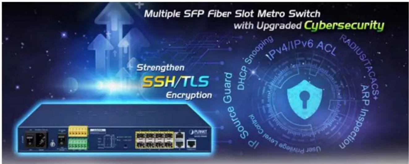
Cybersecurity Network Solution to Minimize Security Risks
The MGSD-10080F supports SSHv2 and TLS protocols to provide strong protection against advanced threats. It includes a range of cybersecurity features such as DHCP Snooping, IP Source Guard, ARP Inspection Protection, 802.1x port-based network access control, RADIUS and TACACS+ user accounts management, SNMPv3 authentication, and so on to complement it as an all-security solution.
Redundant Ring, Fast Recovery for Critical Network Applications
The MGSD-10080F supports redundant ring technology and features strong, rapid self-recovery capability to prevent interruptions and external intrusions. It incorporates advanced ITU-T G.8032 ERPS (Ethernet Ring Protection Switching) technology, Spanning Tree Protocol (802.1s MSTP) into customer's network to enhance system reliability and uptime in various environments.

flowchart
graph TD
    subgraph Office A
        A1["MGSD-10080F"]
        A2["IP Phone"]
        A3["Server"]
    end
    subgraph Office B
        B1["MGSD-10080F"]
        B2["PC"]
        B3["Internet"]
    end
    subgraph Office C
        C1["Speed Dome"]
        C2["NVR"]
    end
    A1 -->|1000| B1
    B1 -->|1000| C1
    C1 -->|1000| B2
    B2 -->|1000| C2
    C2 -->|1000| B3
    style Office A fill:#f9f,stroke:#333
    style Office B fill:#ccf,stroke:#333
    style Office C fill:#cfc,stroke:#333
AC and DC Redundant Power to Ensure Continuous Operation
To enhance the operation reliability and flexibility, the MGSD-10080F is equipped with one 100 \~ 240V AC power supply unit and two additional 36 \~ 60V DC power input connectors for redundant power supply installation. The Redundant Power Systems are specifically designed to handle the demands of high tech facilities requiring the highest power integrity.
Furthermore, with the 36\~60V DC power supply implemented, the MGSD-10080F can be applied as the telecom level device that could be located in the electronic room.
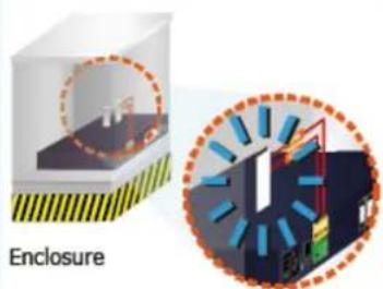
Digital Input and Digital Output for External Alarm
The MGSD-10080F supports Digital Input, and Digital Output on the front panel. The external alarm offers technicians the ability to use Digital Input to detect, and log external device status (such as door intrusion detector) for the alarm as Digital Output could be used to alarm if the MGSD-10080F has port link down, link up or power failure.
Digital Input
Security OK!!
natural_image
Illustration of a device with a circular inset showing internal components and light rays, labeled 'Enclosure' (no text or symbols on main diagram)Door Detector (Door Closed)
Alarm Warning
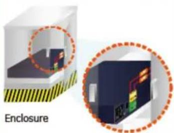
Door Detector (Door Open)
Alarm Messaging
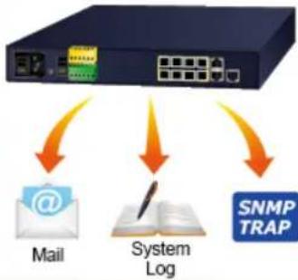
flowchart
graph TD
    A["Mail"] --> B["System Log"]
    B --> C["SNMP TRAP"]
    D["Data Port"] --> A
    E["Network Port"] --> A
Digital Output
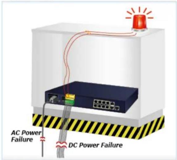
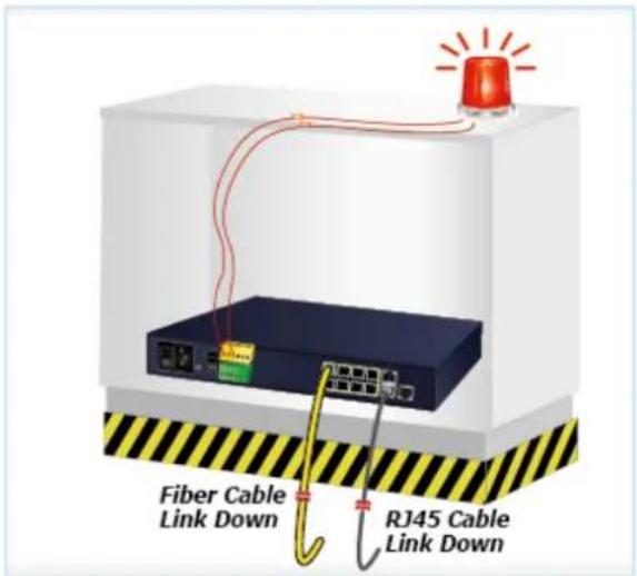
Environmentally-friendly, Fanless Design for Silent Operation
The MGSD-10080F with a desktop-sized metal housing is designed to operate quietly and effectively as it is fanless and comes with optimal power output capability. Thus, the MGSD-10080F can be deployed in any environment without affecting its performance.
Cost-effective IPv6 Managed Gigabit Switch Solution for Metro Ethernet
To fulfill the demand for ISP to build the IPv6 (Internet Protocol version 6) network infrastructure speedily, the MGSD-10080F supports both IPv4 and IPv6 management functions. It can work with original IPv4 network structure and also support the new IPv6 network structure. With easy and friendly management interfaces and plenty of management functions included, the MGSD-10080F Metro Ethernet Switch is the best choice for ISP and service providers to build the IPv6 FTTx edge service and for Industries to connect with IPv6 network.
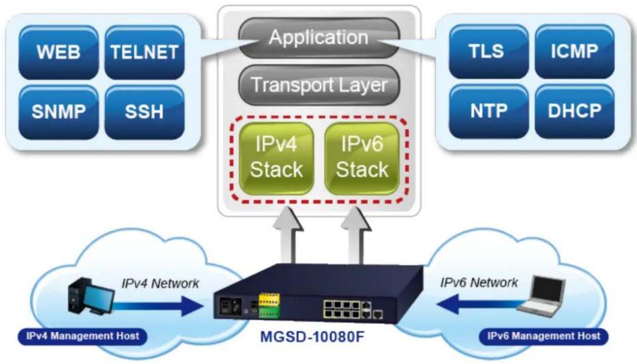
flowchart
graph TD
    A["Application"] --> B["Transport Layer"]
    B --> C["IPv4 Stack"]
    B --> D["IPv6 Stack"]
    E["Network Management Host"] --> F["IPv4 Network"]
    F --> G["MGSD-10080F"]
    G --> H["IPv6 Network"]
    H --> I["IPv6 Management Host"]
    J["Web"] --> K["TELNET"]
    L["SNMP"] --> M["SSH"]
    N["TLS"] --> O["ICMP"]
    P["NTP"] --> Q["DHCP"]
Robust Layer 2 Features
The MGSD-10080F can be programmed for advanced switch management functions such as dynamic port link aggregation, 802.1Q VLAN and Q-in-Q VLAN, Multiple Spanning Tree protocol (MSTP), loop and BPDU guard, IGMP snooping, and MLD snooping. Via the link aggregation, the MGSD-10080F allows the operation of a high-speed trunk to combine with multiple ports, and supports fail-over as well. Also, the Link Layer Discovery Protocol (LLDP) is the Layer 2 protocol included to help discover basic information about neighboring devices on the local broadcast domain.
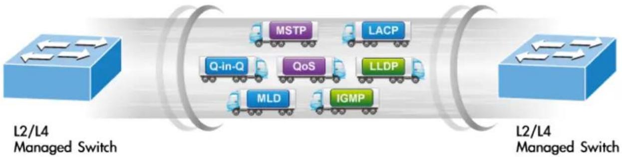
flowchart
graph LR
    A["L2/L4 Managed Switch"] --> B["Service Bus"]
    B --> C["MSTP"]
    B --> D["LACP"]
    B --> E["Q-in-Q"]
    B --> F["QoS"]
    B --> G["LLDP"]
    B --> H["MLD"]
    B --> I["IGMP"]
    J["L2/L4 Managed Switch"] --> K["Service Bus"]
    K --> L["MSTP"]
    K --> M["LACP"]
    K --> N["Q-in-Q"]
    K --> O["QoS"]
    K --> P["LLDP"]
    K --> Q["MLD"]
    K --> R["IGMP"]
Efficient Traffic Control
The MGSD-10080F is loaded with robust QoS features and powerful traffic management to enhance services to business-class data, voice, and video solutions. The functionality includes broadcast/multicast storm control, per port bandwidth control, IP DSCP QoS priority and remarking. It guarantees the best performance for VoIP and video stream transmission, and empowers the enterprises to take full advantage of the limited network resources.
Powerful Security
The MGSD-10080F offers comprehensive Layer 2 to Layer 4 Access Control List (ACL) for enforcing security to the edge. It can be used to restrict network access by denying packets based on source and destination IP address, TCP/UDP ports or defined typical network applications. Its protection mechanism also comprises 802.1x Port-based user authentication. With the private VLAN function, communication between edge ports can be prevented to ensure user privacy. The network administrators can now construct highly-secure corporate networks with considerably less time and effort than before
Friendly and Secure Management
For efficient management, the MGSD-10080F is equipped with Command line, Web and SNMP management interfaces.
■ With the built-in Web-based management interface, the MGSD-10080F offers an easy-to-use, platform-independent management and configuration facility.
■ For text-based management, it can be accessed via Telnet and the console port.
By supporting the standard SNMP protocol, the switch can be managed via any SNMP-based management software.
Moreover, the MGSD-10080F offers secure remote management by supporting SSHv2, TLSv1.2 and SNMP v3 connections which encrypt the packet content at each session.
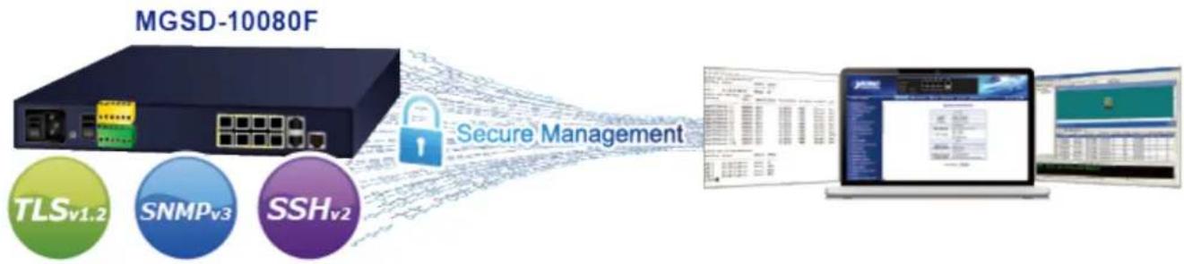
flowchart
graph LR
    A["MGSD-10080F Server"] -->|Secure Management| B["Security Management"]
    subgraph TLS_v1.2
        C["TLS_v1.2"]
        D["SNMP_v3"]
        E["SSH_v2"]
    end
    subgraph SNMP_v3
        F["SNMP_v3"]
        G["SSH_v2"]
    end
    subgraph SSH_v2
        H["SSH_v2"]
    end
    B --> I["Computer Interface"]
    I --> J["Database Interface"]
    J --> K["Database Server"]
    K --> L["Database Server"]
Flexibility and Extension Solution
The mini-GBIC slots built in the MGSD-10080F support multi-speed, 100BASE-FX, 1000BASE-SX/LX and 2500BASE-X SFP (Small Form-factor Pluggable) fiber-optic modules, meaning the administrator now can flexibly choose the suitable SFP transceiver according to not only the transmission distance but also the transmission speed required. The distance can be extended from 300 meters to 2 kilometers (multi-mode fiber) and up to above 10/20/40/60/80/120 kilometers (single-mode fiber or WDM fiber). They are well suited for applications within the enterprise data centers and distributions.
Intelligent SFP Diagnosis Mechanism
The MGSD-10080F supports SFP-DDM (Digital Diagnostic Monitor) function that can easily monitor real-time parameters of the SFP for network administrator, such as optical output power, optical input power, temperature, laser bias current, and transceiver supply voltage.
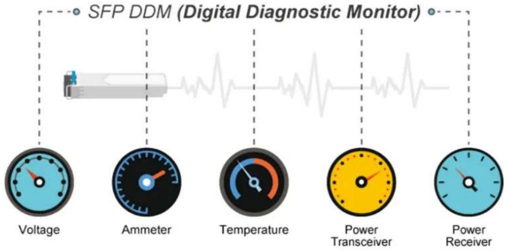
flowchart
graph LR
    A["SFP DDM (Digital Diagnostic Monitor)"] --> B["Voltage"]
    A --> C["Ammeter"]
    A --> D["Temperature"]
    A --> E["Power Transceiver"]
    A --> F["Power Receiver"]
1588 Time Protocol for Industrial Computing Networks
The MGSD-10080F is ideal for telecom and Carrier Ethernet applications, supporting MEF service delivery and timing over packet solutions for IEEE 1588 and synchronous Ethernet.
Time Synchronization in Network

flowchart
graph TD
    A["Grand Master"] -->|1588 PTP| B["MGSD-10080F Transparent Clock"]
    B --> C["Slave"]
    C --> D["Base Station"]
    D --> E["Base Station"]
    E --> F["Base Station"]
    F --> G["Base Station"]
    G --> H["1000BASE-SX/LX Fiber Optic"]
    C --> I["1588 PTP"]
1.3 How to Use This Manual
This User's Manual is structured as follows:
Section 2, INSTALLATION
The section explains the functions of the Managed Metro Switch and how to physically install the Managed Metro Switch.
Section 3, SWITCH MANAGEMENT
The section contains the information about the software function of the Managed Metro Switch.
Section 4, WEB CONFIGURATION
The section explains how to manage the Managed Metro Switch by Web interface.
Section 5. SWITCH OPERATION
The chapter explains how to do the switch operation of the Managed Metro Switch.
Section 6. TROUBLESHOOTING
The chapter explains how to do troubleshooting of the Managed Metro Switch.
Appendix A
The section contains cable information of the Managed Metro Switch.
Appendix B
The section contains glossary information of the Managed Metro Switch.
1.4 Product Features
Physical Port
■ 6 100/1000BASE-X SFP mini-GBIC slots (Port 1 to port 6)
■ 2 100/1000/2500BASE-X mini-GBIC/SFP slots for SFP type auto detection(Port 7 to port 8)
■ 2-Port 10/100/1000BASE-T Gigabit Ethernet RJ45 (Port 9 to port 10)
■ One RJ45 console interface for basic management and setup
Redundant Power System
■ Redundant Power System: 100V \~ 240V AC/Dual 36V \~ 60V DC
■ Active-active redundant power failure protection
■ Backup of catastrophic power failure on one supply
■ Fault tolerance and resilience.
Digital Input / Digital Output
■ 2 Digital Input (DI)
■ 2 Digital Output (DO)
■ Integrates sensors into auto alarm system
■ Transfer alarm to IP network via SNMP trap
Industrial Protocol
■ IEEE 1588v2 PTP (Precision Time Protocol) Transparent Clock mode
Hardware Design
■ -10 to 60 degrees C operating temperature for DC power input only
■ 13-inch desktop size, 19-inch Rack-mountable
■ Relay alarm for port breakdown, power failure
■ Fanless design
Layer 2 Features
■ Prevents packet loss with back pressure (half-duplex) and IEEE 802.3x pause frame flow control (full-duplex)
■ High performance of Store-and-Forward architecture and runt/CRC filtering eliminate erroneous packets to optimize the network bandwidth
■ Storm Control support
- Broadcast / Multicast / Unicast
■ Supports VLAN
- IEEE 802.1Q tagged VLAN
- Up to 4K VLANs groups, out of 4094 VLAN IDs
– Supports provider bridging (VLAN Q-in-Q, IEEE 802.1ad) - Private VLAN Edge (PVE)
- Port Isolation
- MAC-based VLAN
- IP Subnet-based VLAN
- Protocol-based VLAN
- VLAN Translation
- Voice VLAN
- GVRP
■ Supports Spanning Tree Protocol
- STP, IEEE 802.1D Spanning Tree Protocol
- RSTP, IEEE 802.1w Rapid Spanning Tree Protocol
- MSTP, IEEE 802.1s Multiple Spanning Tree Protocol, spanning tree by VLAN
- BPDU Filtering/BPDU Guard
■ Supports Link Aggregation
- 802.3ad Link Aggregation Control Protocol (LACP)
– Cisco ether-channel (Static Trunk)
– Maximum 5 trunk groups, up to 8 ports per trunk group - Up to 16Gbps bandwidth (Duplex Mode)
■ Provides port mirror (1-to-1)
■ Port mirroring to monitor the incoming or outgoing traffic on a particular port
■ Loop protection to avoid broadcast loops
■ Supports ERPS (Ethernet Ring Protection Switching)
■ Compatible with Cisco Uni-directional link detection(UDLD) that monitors a link between two switches and blocks the ports on both ends of the link if the link fails at any point between the two devices
■ Link Layer Discovery Protocol (LLDP) and LLDP-MED
Quality of Service
■ Ingress Shaper and Egress Rate Limit per port bandwidth control
■ 8 priority queues on all switch ports
■ Traffic classification
- IEEE 802.1p CoS
- IP TOS / DSCP / IP Precedence
- IP TCP/UDP port number
- Typical network application
■ Strict priority and Weighted Round Robin (WRR) CoS policies
■ Supports QoS and In/Out bandwidth control on each port
■ Traffic-policing policies on the switch port
■ DSCP remarking
Multicast
■ Supports IPv4 IGMP Snooping v1, v2 and v3
■ Supports IPv6 MLD Snooping v1 and v2
■ Querier mode support
■ IGMP Snooping port filtering
■ MLD Snooping port filtering
■ MVR (Multicast VLAN Registration)
Security
■ Authentication
– IEEE 802.1x Port-based/MAC-based network access authentication
Built-in RADIUS client to co-operate with the RADIUS servers
- TACACS+ login users access authentication
- RADIUS/TACACS+ users access authentication
■ Access Control List
- IP-based Access Control List (ACL)
- MAC-based Access Control List
■ Source MAC/IP address binding
■ DHCP Snooping to filter un-trusted DHCP messages
■ Dynamic ARP Inspection discards ARP packets with invalid MAC address to IP address binding
■ IP Source Guard prevents IP spoofing attacks
■ IP address access management to prevent unauthorized intruder
Management
■ IPv4 and IPv6 dual stack management
■ Switch Management Interfaces
- Web switch management
- Console/Telnet Command Line Interface
- SNMP v1 and v2c switch management
- SSHv2, TLSv1.2 and SNMP v3 secure access
■ IPv6 IP Address/NTP/DNS management
■ Built-in Trivial File Transfer Protocol (TFTP) client
■ BOOTP and DHCP for IP address assignment
■ System Maintenance
- Firmware upload/download via HTTP/TFTP
- Configuration upload/download via HTTP/TFTP
- Reset button for system reboot or reset to factory default
- Dual Images
■ DHCP Relay
■ DHCP Option82
■ DHCP Server
■ User Privilege levels control
■ NTP (Network Time Protocol)
■ UPnP
■ Link Layer Discovery Protocol (LLDP) and LLDP-MED
■ Network Diagnostic
- SFP-DDM (Digital Diagnostic Monitor)
- ICMPv6/ICMPv4 Remote Ping
– Cable Diagnostic technology provides the mechanism to detect and report potential cabling issues
■ SMTP/Syslog remote alarm
■ Four RMON groups (history, statistics, alarms and events)
■ SNMP trap for interface Linkup and Linkdown notification
■ System Log
■ PLANET Smart Discovery Utility for deployment management
■ PLANET NMS system and CloudViewer for deployment management
1.5 Product Specifications
| Product | MGSD-10080F |
| Hardware Specifications | |
| SFP Fiber Optic Ports | 6 1000BASE-SX/LX/BX SFP interfaces, from port 1 to port 6Compatible with 100BASE-FX SFP. |
| 2 100/1000/2500BASE-X SFP interfaces, from port 7 to port 8 | |
| Copper Ports | 2 10/ 100/1000BASE-T RJ45 auto-MDI/MDI-X ports (Port-9 and Port-10) |
| Console | 1 x RJ45 serial port (115200, 8, N, 1) |
| Reset Button | < 5 sec: System reboot> 5 sec: Factory default |
| Power Requirements | AC 100~240V, 50/60Hz 0.15A-36V DC @ 0.3A, Range: -36V ~ -60V DC |
| Power Consumption | Max. 11.2 watts/38.2 BTU (AC input)Max. 10.8 watts/36.9 BTU (DC input) |
| Alarm | One relay output for power failure. Alarm Relay current carry ability: 1A @ DC 24V |
| DI/DO | 2 Digital Input (DI): Level 0: -24V~2.1V (±0.1V)Level 1: 2.1V~24V (±0.1V)Input Load to 24V DC, 10mA max.2 Digital Output (DO): Open collector to 24VDC, 100mA max. |
| ESD Protection | 6KV DC |
| Dimensions (W x D x H) | 330 x 155 x 43.5 mm, 1U high |
| Weight | 1661g |
| LED | System:PWR (Green)DC 1 (Green)DC 2 (Green)Fault Alarm (Green)Ring (Green)Ring Owner (Green)Per Gigabit SFP Ports: Port 1 to Port 6.100 LNK/ACT (Orange)1G LNK/ACT (Green)Per Gigabit SFP Ports: Port 7 to Port 8.100 LNK/ACT (Orange)1G/2.5G LNK/ACT (Green)Per Gigabit RJ45 Ports: Port 9 to Port 10.10/100 LNK/ACT (Orange)1G LNK/ACT (Green) |
| Switching | |
| Switch Architecture | Store-and-Forward |
| Switch Fabric | 26Gbps/non-blocking |
| Throughput (packet per second) | 19.3Mpps @ 64Bytes packet |
| Address Table | 8K entries, automatic source address learning and aging |
| SDRAM | 256Mbits |
| Flash | 64Mbytes |
| Flow Control | IEEE 802.3x pause frame for full-duplexBack pressure for half-duplex |
| Jumbo Frame 9KB | |
| Layer 2 Functions | |
| Port Configuration | Port disable / enableAuto-Negotiation 10/100/1000Mbps full and half duplex mode selectionFlow Control disable / enableBandwidth control on each portPower saving mode control |
| Port Status | Display each port's speed duplex mode, link status, flow control status, auto negotiation status, trunk status |
| Port Mirroring | TX/RX/Both1 to 1 monitor |
| VLAN | 802.1Q tag-based VLANQ-in-Q tunnelingPrivate VLAN Edge (PVE)MAC-based VLANProtocol-based VLANVLAN TranslationVoice VLANMVR (Multicast VLAN Registration)GVRPUp to 4K VLAN groups, out of 4094 VLAN IDs |
| Link Aggregation | IEEE 802.3ad LACP/Static TrunkSupports 5 groups of 8-Port trunk support |
| Spanning Tree Protocol | IEEE 802.1D Spanning Tree ProtocolIEEE 802.1w Rapid Spanning Tree ProtocolIEEE 802.1s Multiple Spanning Tree Protocol |
| QoS | Traffic classification based, strict priority and WRR8-level priority for switching- Port number- 802.1p priority- 802.1Q VLAN tag- DSCP/TOS field in IP packet |
| Ring | Supports ERPS, and complies with ITU-T G.8032 |
| IGMP Snooping | IGMP (v1/v2/v3) Snooping, up to 255 multicast groupsIGMP Querier mode support |
| MLD Snooping | MLD (v1/v2) Snooping, up to 255 multicast groupsMLD Querier mode support |
| Bandwidth Control | Per port bandwidth controlIngress: 500Kb~1000MbpsEgress: 500Kb~1000Mbps |
| Security Functions | |
| Access Control List | IP-based ACL/MAC-based ACLACL based on:- MAC Address |
| - IP Address- Ethertype- Protocol Type- VLAN ID- DSCP- 802.1p PriorityUp to 123 entries | |
| Security | Port SecurityIP source guardDynamic ARP inspectionCommand line authority control based on user level |
| AAA | RADIUS clientTACACS+ client |
| Network Access Control | IEEE 802.1x port-based network access controlMAC-based authenticationLocal/RADIUS authentication |
| Switch Management Functions | |
| Basic Management Interfaces | Console; Telnet; Web Browser; SNMP v1, v2c |
| Secure Management Interfaces | SSHv2, TLS v1.2, SNMP v3 |
| System Management | Firmware upgrade by HTTP protocol through Ethernet networkConfiguration upload/download through HTTPRemote SyslogSystem logLLDP protocolNTPPLANET Smart Discovery UtilityPLANET NMS system and CloudViewer |
| Event Management | Remote SyslogLocal System logSMTP |
| SNMP MIBs | RFC 1213 MIB-IIRFC 2863 IF-MIBRFC 1493 Bridge MIBRFC 1643 Ethernet MIBRFC 2863 Interface MIBRFC 2665 Ether-Like MIBRFC 2737 Entity MIBRFC 2819 RMON MIB (Groups 1, 2, 3 and 9)RFC 2618 RADIUS Client MIBRFC 3411 SNMP-Frameworks-MIBIEEE 802.1X PAELLDPMAU-MIB |
| Standards Conformance | |
| Regulatory Compliance | FCC Part 15 Class A, CE |
| Standards Compliance | IEEE 802.3 10BASE-TIEEE 802.3u 100BASE-TX/100BASE-FXIEEE 802.3ab Gigabit 1000TIEEE 802.3z Gigabit SX/LXIEEE 802.3bz 2.5GBASE-XIEEE 802.3x flow control and back pressureIEEE 802.3ad port trunk with LACPIEEE 802.1D Spanning Tree ProtocolIEEE 802.1w Rapid Spanning Tree ProtocolIEEE 802.1s Multiple Spanning Tree ProtocolIEEE 802.1p Class of ServiceIEEE 802.1Q VLAN taggingIEEE 802.1ad Q-in-Q VLAN stackingIEEE 802.1X Port Authentication Network ControlIEEE 802.1ab LLDPIEEE 802.3ah OAMIEEE 802.1ag Connectivity Fault Management (CFM)RFC 768 UDPRFC 793 TFTPRFC 791 IPRFC 792 ICMPRFC 2068 HTTPRFC 1112 IGMP v1RFC 2236 IGMP v2RFC 3376 IGMP version 3RFC 2710 MLD version 1RFC 3810 MLD version 2ITU-T G.8032 ERPS RingITU-T Y.1731 Performance Monitoring |
| Environments | |
| Operating | Temperature: -10 ~ 60 degrees C for DC power input0 ~ 50 degrees C for AC power inputRelative Humidity: 5 ~ 95% (non-condensing) |
| Storage | Temperature: -10 ~ 70 degrees CRelative Humidity: 5 ~ 95% (non-condensing) |
2. INSTALLATION
2.1 Hardware Description
This section describes the hardware features and installation of the Managed Metro Switch on the desktop or rack mount. For easier management and control of the Managed Metro Switch, familiarize yourself with its display indicators, and ports. Front panel illustrations in this chapter display the unit LED indicators. Before connecting any network device to the Managed Metro Switch, please read this chapter completely.
2.1.1 Switch Front Panel
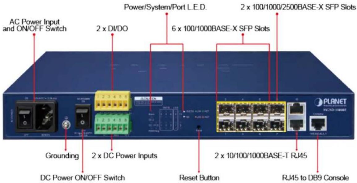
The front panel provides a simple interface monitoring the Managed Metro Switch. Figure 2-1 show the front panel.
Front Panel

Figure 2-1: MGSD-10080F Front Panel
■ AC Power Receptacle
For compatibility with electric service in most areas of the world, the Managed Metro Switch's power supply automatically adjusts to line power in the range of 100-240V AC and 50/60 Hz.
Plug the female end of the power cord firmly into the receptalbe on the front panel of the Managed Metro Switch. Plug the other end of the power cord into an electric service outlet and then the power will be ready.
The device is a power-required device, which means it will not work till it is powered. If your networks should be active all the time, please consider using UPS (Uninterrupted Power Supply) for your device.
Power Notice: It will prevent you from network data loss or network downtime. In some areas, installing a surge suppression device may also help to protect your Managed Metro Switch from being damaged by unregulated surge or current to the Switch or the power adapter.
DC Power Connector
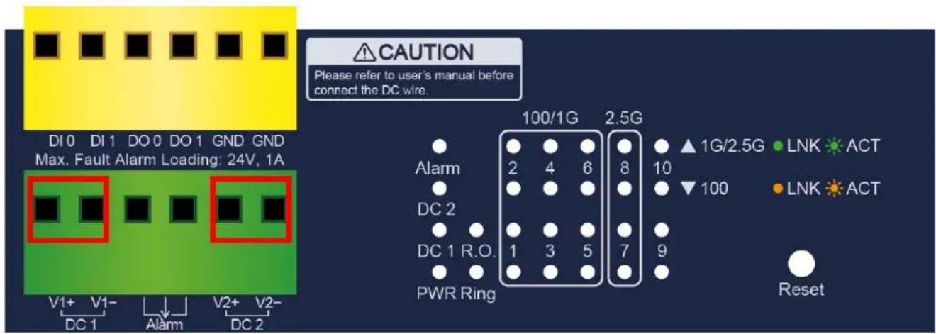
The front panel of the Managed Metro Switch contains a power switch and a DC power connector, which accepts DC power input voltage from -36V to -60V DC. Connect the power cable to the Managed Metro Switch at the input terminal block. The size of the two screws in the terminal block is M3.5.
Digital Input
The digitail input of the Managed Metro Switch can be activated by the external sensor that senses physical changes.
These changes can include intrusion detection or certain physical change in the monitored area. For examples, the external sensor can be a door switch or an infrared motion detector.
Digital Output
The digital output main function is to allow the Managed Metro Switch to trigger external devices, either automatically or by remote control from a human operator or a software application.
■ 100/1000BASE-X SFP Slots (port 1 to port 6)
Each of the SFP (Small Form-factor Pluggable) slot supports dual-speed, 1000BASE-SX/LX or 100BASE-FX
- For 1000BASE-SX/LX SFP transceiver module: From 550 meters (multi-mode fiber) to 10/20/40/60/80/120 kilometers (single-mode fiber).
- For 100BASE-FX SFP transceiver module: From 2 kilometers (multi-mode fiber) to 20/40/60 kilometers (single-mode fiber).
■ 100/1000/2500BASE-X SFP Slots (port 7 to port 8)
Each of the SFP (Small Form-factor Pluggable) slot supports triple-speed, 2500BASE-X,1000BASE-SX/LX or 100BASE-FX
- For 2500BASE-X SFP transceiver module: From 330 meters (multi-mode fiber) to 2/20kilometers (single-mode fiber).
- For 1000BASE-SX/LX SFP transceiver module: From 550 meters (multi-mode fiber) to 10/20/40/60/80/120 kilometers (single-mode fiber).
- For 100BASE-FX SFP transceiver module: From 2 kilometers (multi-mode fiber) to 20/40/60 kilometers (single-mode fiber).
Gigabit TP Interface(port 9 to port 10)
10/100/1000BASE-T Copper, RJ45 twisted-pair: Up to 100 meters.
Console Port
The console port is an RJ45 port connector. It is an interface for connecting a terminal directly. Through the console port, it provides rich diagnostic information including IP Address setting, factory reset, port management, link status and system setting. Users can use the attached DB9 to RJ45 console cable in the package and connect to the console port on the device. After the connection, users can run any terminal emulation program (Hyper Terminal, ProComm Plus, Telix, Winterm and so on) to enter the startup screen of the device.
Reset Button
In the middle of the front panel, the reset button is designed for rebooting the Managed Metro Switch without turning off and on the power. The following is the summary table of Reset button function:
| Reset Button Pressed and Released | Function |
| < 5 seconds: Switch Reboot> 5 seconds: Factory Default | Reset the Managed Metro Switch to Factory Default configuration. The Managed Metro Switch will then reboot and load the default settings as shown below:Default Username: adminDefault Password: adminDefault IP address: 192.168.0.100Subnet mask: 255.255.255.0Default Gateway: 192.168.0.254 |
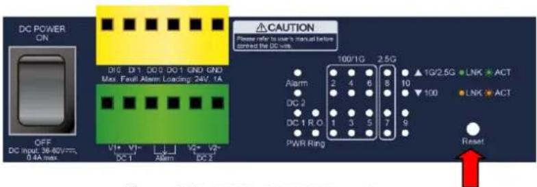
Figure 2-2: MGSD-10080F Reset Button
2.1.2 LED Indicators
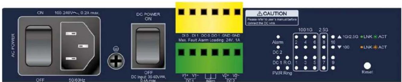
■ LED Definition
■ System
| LED Color Function | ||
| PWR Green | Lights to indicate that the Managed Metro Switch is powered on by AC input. | |
| DC1 Green | Lights to indicate that the Managed Metro Switch is powered on by DC1 input. | |
| DC2 Green | Lights to indicate that the Managed Metro Switch is powered on by DC2 input. | |
| Alarm Green | Lights to indicate that Managed Metro Switch AC/DC or port has failed. | |
| Ring | Green | Lights to indicate that the ERPS Ring has been created successfully. |
| R.O | Green | Lights to indicate that Switch Ring Owner has been enabled. |
■ Per 100/1000 SFP Interface (Port 1 to port 6)
| LED Color Function | ||
| 1000LNK/ACT | Green | Lights: To indicate the link through that port is successfully established at the speed of 1000Mbps. |
| Blink: To indicate that the switch is actively sending or receiving data over that port. | ||
| Off: If 1000 LNK/ACT LED is lit, it indicates the port is operating at 1000Mbps.If 1000 LNK/ACT LED is off, it indicates that the port is link down or operating at 100Mbps. | ||
| 100LNK/ACT | Orange | Lights: To indicate the link through that port is successfully established at the speed of 100Mbps. |
| Blink: To indicate that the switch is actively sending or receiving data over that port. | ||
| Off: If 100 LNK/ACT LED is lit, it indicates the port is operating at 100MbpsIf 100 LNK/ACT LED is off, it indicates that the port is link down or operating at 1000Mbps. | ||
■ Per 100/1000/2500 SFP Interface (Port 7 to port 8)
| LED Color Function | ||
| 1G/2.5GLNK/ACT | Green | Lights: To indicate the link through that port is successfully established at the speed of 1000Mbps or 2500Mbps. |
| Blink: To indicate that the switch is actively sending or receiving data over that port. | ||
| Off: If 1G/2.5G LNK/ACT LED is lit, it indicates the port is operating at 1000Mbps or 2500Mbps.If 1G/2.5G LNK/ACT LED is off, it indicates that the port is link down or operating at 100Mbps. | ||
| 100LNK/ACT | Orange | Lights: To indicate the link through that port is successfully established at the speed of 100Mbps. |
| Blink: To indicate that the switch is actively sending or receiving data over that port. | ||
| Off: If 100 LNK/ACT LED is lit, it indicates that the port is operating at 100MbpsIf 100 LNK/ACT LED is off, it indicates the port is link down or operating at 1000Mbps or 2500Mbps. | ||
■ Per 10/100/1000BASE-T Interface (Port 9 to port 10)
| LED Color Function | ||
| 1000LNK/ACT | Green | Lights: To indicate the link through that port is successfully established at the speed of 1000Mbps. |
| Blink: To indicate that the switch is actively sending or receiving data over that port. | ||
| Off: If 1000 LNK/ACT LED is lit, it indicates the port is operating at 1000Mbps.If 1000 LNK/ACT LED is off, it indicates that the port is link down or operating at 10/100Mbps . | ||
| 10/100LNK/ACT | Orange | Lights: To indicate the link through that port is successfully established at the speed of 10Mbps or 100Mbps. |
| Blink: To indicate that the switch is actively sending or receiving data over that port. | ||
| Off: If 10/100 LNK/ACT LED is lit, it indicates the port is operating at 10/100Mbps.If 10/100 LNK/ACT LED is off, it indicates the port is link down or operating at 1000Mbps. | ||
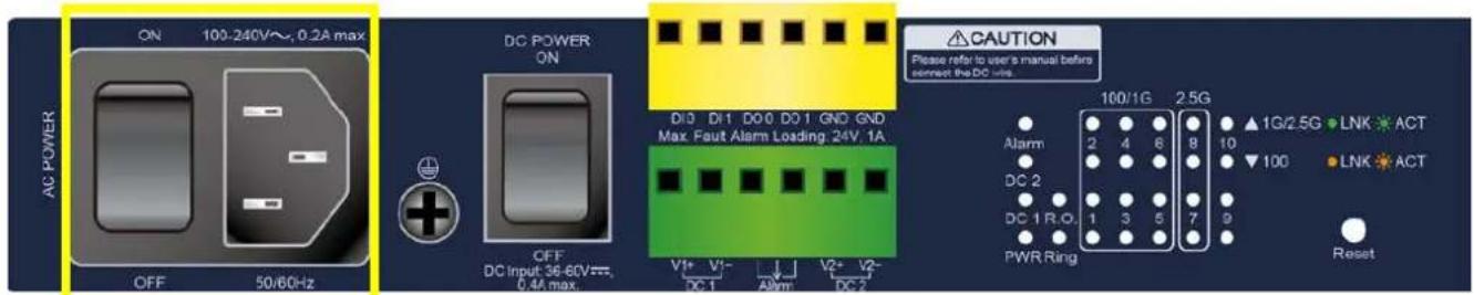
2.1.2 Wiring the AC Power Input
The front panel of the MGSD-10080F indicates an AC inlet power socket, which accepts input power from 100 to 240V AC, 50/60Hz.
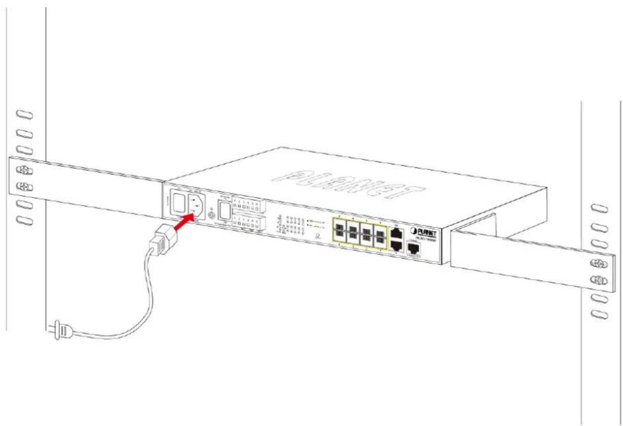
2.1.3 Wiring the DC Power Input
The Front Panel of the Managed Metro Switch indicates a DC inlet power socket and consists of one terminal block connector within 6 contacts. Please follow the steps below to insert the power wire.
- Insert positive/negative DC power wires into the contacts 1 and 2 for DC POWER 1, or 5 and 6 for DC POWER 2.
- Tighten the wire-clamp screws for preventing the wires from loosening.
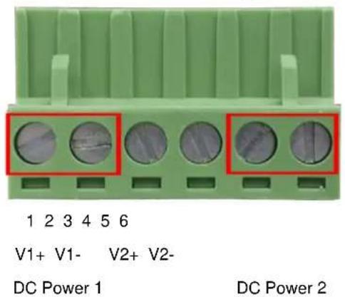
| Positive (+) Pin Negative | (-) Pin | |
| Managed Metro Switch | Pin 1 / 5 | Pin 2 / 6 |

The wire gauge for the terminal block should be in the range from 12 to 24 AWG.
2.1.4 Wiring the Fault Alarm Contact
The fault alarm contacts are in the middle (3 & 4) of the terminal block connector as the picture shows below. Inserting the wires, the Managed Metro Switch will detect the fault status of the power failure, or port link failure (available for managed model). The following illustration shows an application example for wiring the fault alarm contacts.
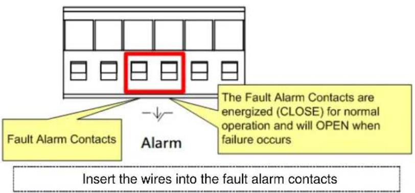

- The wire gauge for the terminal block should be in the range from 12 to 24 AWG.
- When performing any of the procedures like inserting the wires or tightening the wire-clamp screws, make sure the power is OFF to prevent from getting an electric shock.
2.1.5 Wiring the Digital Input/Output
The 6-contact terminal block connector on the front panel of Managed Metro Switch is used for Digital Input and Digital Output. Please follow the steps below to insert wire.
- The Managed Metro Switch offers two DI and DO groups. 1 and 2 are DI groups, 3 and 4 are DO groups and 5 and 6 are GND (ground).
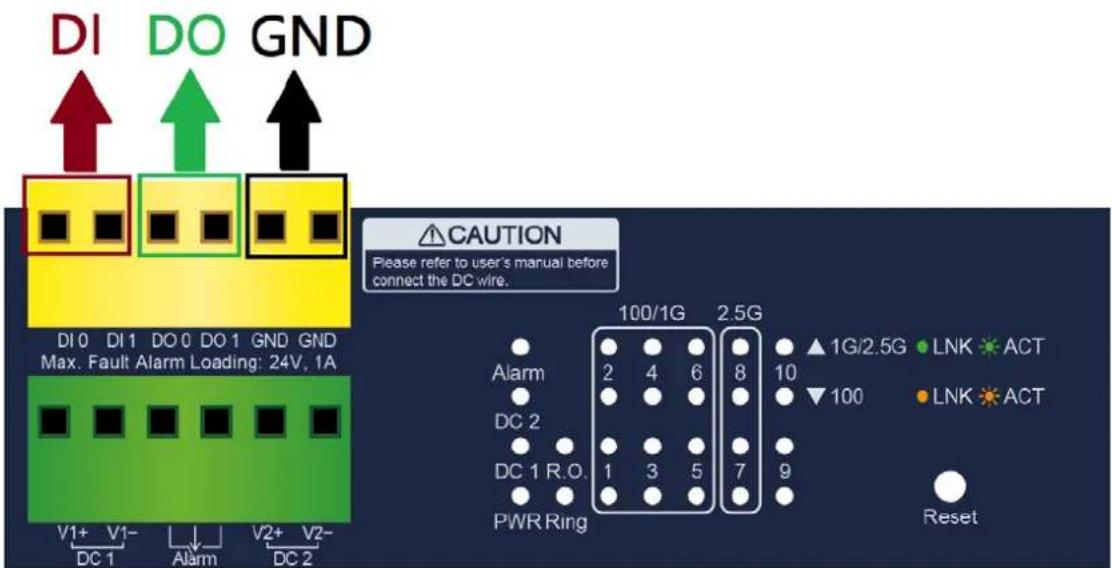
Figure 2-3: Wiring the Digital Input/Digital Output and Ground
- Tighten the wire-clamp screws for preventing the wires from loosening.
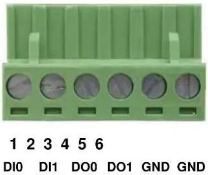
Figure 2-4: 6-pin Terminal Block for DI and DO Wiring Input
- There are two Digital Input groups for you to monitor two different devices. The following topology shows how to wire DI0 and DI1.
Figure 2-5: Wiring DI0 and DI1 to Open Detector
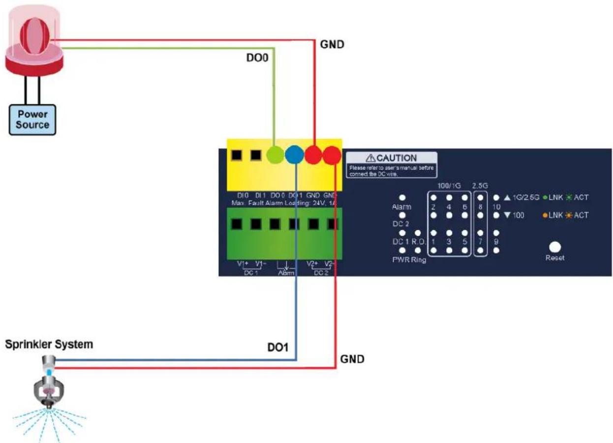
- There are two Digital Output groups for you to sense Managed Metro Switch port failure or power failure and issue a high or low signal to external device. The following topology shows how to wire DO0 and DO1.
flowchart
graph TD
    A["Power Source"] --> B["DO0"]
    B --> C["GND"]
    C --> D["Max Fault Alarm Loading: 24V, 1A"]
    D --> E["DO1"]
    E --> F["Sprinkler System"]
    F --> G["GND"]
    G --> H["CAUTION"]
    H --> I["Please refer to user's manual before connected the DC wire."]
    I --> J["Alarm 100/1G 2.5G"]
    I --> K["DC 2 100 100"]
    I --> L["PWR Ring 7 9 Reset"]
Figure 2-6: Wiring DO0 and DO1 to Open Detector
2.2 Installing the Managed Metro Switch
This section describes how to install your Managed Metro Switch and make connections to the Managed Metro Switch.
Please read the following topics and perform the procedures in the order being presented. To install your Managed Metro
Switch on a desktop or shelf, simply complete the following steps.
In this paragraph, we will describe how to install the Managed Metro Switch and the installation points attended to it.
2.2.1 Desktop Installation
To install the Managed Metro Switch on desktop or shelf, please follow these steps:
Step 1: Attach the rubber feet to the recessed areas on the bottom of the Managed Metro Switch.
Step 2: Place the Managed Metro Switch on the desktop or the shelf near an AC/DC power source as shown in Figure 2-7.
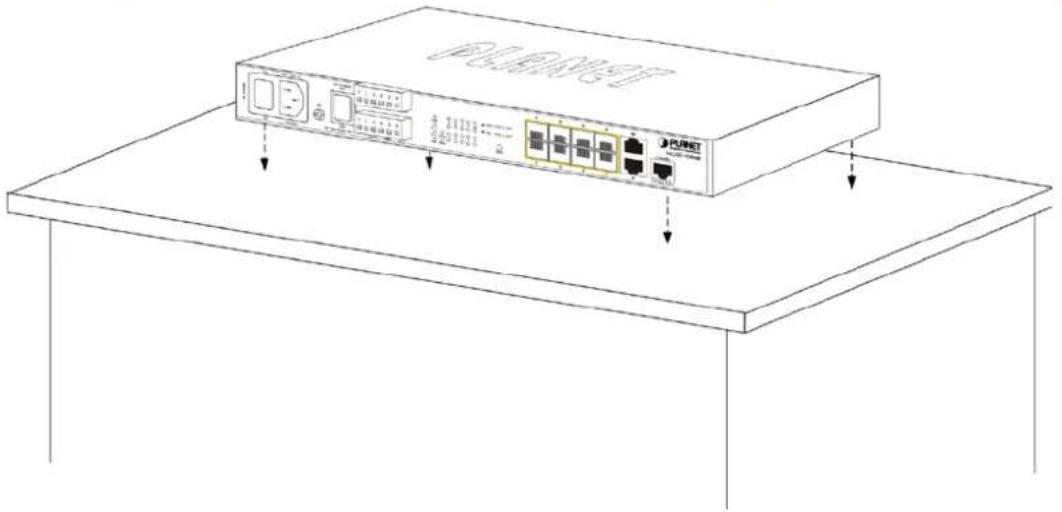
Figure 2-7: Place the Managed Metro Switch on the Desktop
Step 3: Keep enough ventilation space between the Managed Metro Switch and the surrounding objects.
Step 4: Connect the Managed Metro Switch to network devices.
Connect one end of a standard network cable to the 10/100/1000 RJ45 ports on the front of the Managed Metro Switch. Connect the other end of the cable to the network devices such as printer servers, workstations or routers, etc.

Connecting to the Managed Metro Switch requires UTP Category 5 network cabling with RJ45 tips. For more information, please see the Cabling Specification in Appendix A.
Step 5: Supply power to the Managed Metro Switch.
Connect one end of the power cable to the Managed Metro Switch.
Connect the power plug of the power cable to a standard wall outlet.
When the Managed Metro Switch receives power, the Power LED should remain solid Green.
2.2.2 Rack Mounting
To install the Managed Metro Switch in a 19-inch standard rack, please follow the instructions described below.
Step 1: Place the Managed Metro Switch on a hard flat surface, with the front panel positioned towards the front side.
Step 2: Attach the rack-mount bracket to each side of the Managed Metro Switch with supplied screws attached to the package.
Figure 2-8 shows how to attach brackets to one side of the Managed Metro Switch.
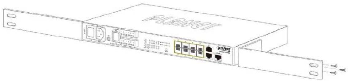
Figure 2-8: Attach Brackets to the Managed Metro Switch.

You must use the screws supplied with the mounting brackets. Damage caused to the parts by using incorrect screws would invalidate the warranty.
Step 3: Secure the brackets tightly.
Step 4: Follow the same steps to attach the second bracket to the opposite side.
Step 5: After the brackets are attached to the Managed Metro Switch, use suitable screws to securely attach the brackets to the rack as shown in Figure 2-9.

natural_image
Line drawing of a network device chassis with ports and connectors (no text or symbols)Figure 2-9: Mounting the Managed Metro Switch on a Rack
Step 6: Proceeds with steps 4 and 5 of session 2.2.1 Desktop Installation to connect the network cabling and supply power to the Managed Metro Switch.
2.3 Cabling
■ 10/100/1000BASE-T
All 10/100/1000BASE-T ports come with auto-negotiation capability. They automatically support 1000BASE-T, 100BASE-TX and 10BASE-T networks. Users only need to plug a working network device into one of the 10/100/1000BASE-T ports, and then turn on the Managed Metro Switch. The port will automatically run at 10Mbps, 20Mbps, 100Mbps or 200Mbps and 1000Mbps or 2000Mbps after negotiating with the connected device.
■ 100BASE-FX/1000BASE-SX/LX/2500BASE-X
The Managed Metro Switch has eight SFP interfaces that support 100/1000/2500Mbps triple speed mode (optional multi-mode/single-mode 100BASE-FX/1000BASE-SX/LX/2500BASE-X SFP module)
| Interface/SFP Mode | 100BASE-FX | 1000BASE-SX/LX | 2500BASE-X |
| Port 1 to Port 6 | NA | ||
| Port 7 to Port 8 |
■ Cabling
Each 10/100/1000BASE-T port uses an RJ45 socket -- similar to phone jacks -- for connection of unshielded twisted-pair cable (UTP). The IEEE 802.3/802.3u 802.3ab Fast/Gigabit Ethernet standard requires Category 5 UTP for 100Mbps 100BASE-TX. 10BASE-T networks can use Cat.3, 4, 5 or 1000BASE-T use 5/5e/6 UTP (see table below). Maximum distance is 100 meters (328 feet). The 100BASE-FX/1000BASE-SX/LX/2500BASE-X SFP slot uses an LC connector with optional SFP module. Please see table below and know more about the cable specifications.
| Port Type | Cable Type | Connector |
| 10BASE-T | Cat3, 4, 5, 2-pair | RJ45 |
| 100BASE-TX | Cat5 UTP, 2-pair | RJ45 |
| 1000BASE-T | Cat5/5e/6 UTP, 2-pair | RJ45 |
| 100BASE-FX | 50/125μm or 62.5/125μm multi-mode 9/125μm single-mode | LC (multi/single mode) |
| 1000BASE-SX/LX | 50/125μm or 62.5/125μm multi-mode 9/125μm single-mode | LC (multi/single mode) |
| 2500BASE-X | 50/125μm or 62.5/125μm multi-mode 9/125μm single-mode | LC (multi/single mode) |
Any Ethernet devices like hubs and PCs can connect to the Managed Metro Switch by using straight-through wires. The two 10/100/1000Mbps ports are auto-MDI/MDI-X and can be used on straight-through or crossover cable.
2.3.1 Installing the SFP Transceiver
The sections describe how to insert an SFP transceiver into an SFP slot.
The SFP transceivers are hot-pluggable and hot-swappable. You can plug in and out the transceiver to/from any SFP port without having to power down the Managed Metro Switch as Figure 2-10 shows below:
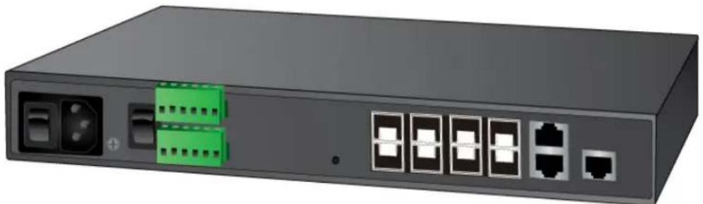
natural_image
Front view of a network switch device with ports and connectors (no visible text or symbols)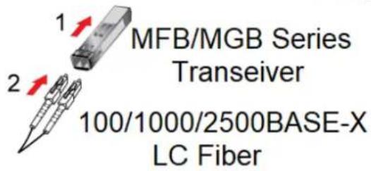
Figure 2-10: Plugging in the SFP Transceiver
■ Approved PLANET SFP Transceivers
PLANET Managed Metro Switch supports both single mode and multi-mode SFP transceivers. The following list of approved PLANET SFP transceivers is correct at the time of publication:
Fast Ethernet Transceiver (100BASE-X SFP)
| Model | DDM | Speed (Mbps) | Connector Interface | Fiber Mode | Distance | Wavelength (nm) | Operating Temp. |
| MFB-FX | -- | 100 | LC | Multi Mode | 2km | 1310nm | 0 ~ 60 °C |
| MFB-F20 | -- | 100 | LC | Single Mode | 20km | 1310nm | 0 ~ 60 °C |
| MFB-F40 | -- | 100 | LC | Single Mode | 40km | 1310nm | 0 ~ 60 °C |
| MFB-F60 | -- | 100 | LC | Single Mode | 60km | 1310nm | 0 ~ 60 °C |
| MFB-F120 | -- | 100 | LC | Single Mode | 120km | 1550nm | 0 ~ 60 °C |
Fast Ethernet Transceiver (100BASE-BX, Single Fiber Bi-directional SFP)
| Model | DDM | Speed (Mbps) | Connector Interface | Fiber Mode | Distance | Wavelength (TX) | Wavelength (RX) | Operating Temp. |
| MFB-FA20 | -- | 100 | WDM(LC) | Single Mode | 20km | 1310nm | 1550nm | 0 ~ 60 °C |
| MFB-FB20 | -- | 100 | WDM(LC) | Single Mode | 20km | 1550nm | 1310nm | 0 ~ 60 °C |
Gigabit Ethernet Transceiver (1000BASE-X SFP)
| Model | DDM | Speed (Mbps) | Connector Interface | Fiber Mode | Distance | Wavelength (nm) | Operating Temp. |
| MGB-GT | -- | 1000 | Copper | -- | 100m | -- | 0 ~ 60 °C |
| MGB-SX(V2) | YES | 1000 | LC | Multi Mode | 550m | 850nm | 0 ~ 60 °C |
| MGB-SX2(V2) | YES | 1000 | LC | Multi Mode | 2km | 1310nm | 0 ~ 60 °C |
| MGB-LX(V2) | YES | 1000 | LC | Single Mode | 20km | 1310nm | 0 ~ 60 °C |
| MGB-L40 | YES | 1000 | LC | Single Mode | 40km | 1310nm | 0 ~ 60 °C |
| MGB-L80 | YES | 1000 | LC | Single Mode | 80km | 1550nm | 0 ~ 60 °C |
| MGB-L120(V2) | YES | 1000 | LC | Single Mode | 120km | 1550nm | 0 ~ 60 °C |
Gigabit Ethernet Transceiver (1000BASE-BX, Single Fiber Bi-directional SFP)
| Model | DDM | Speed (Mbps) | Connector Interface | Fiber Mode | Distance | Wavelength (TX) | Wavelength (RX) | Operating Temp. |
| MGB-LA10(V2) | YES | 1000 | WDM(LC) | Single Mode | 10km | 1310nm | 1550nm | 0 ~ 60 °C |
| MGB-LB10(V2) | 1000 | WDM(LC) | Single Mode | 10km | 1550nm | 1310nm | 0 ~ 60 °C | |
| MGB-LA20(V2) | YES | 1000 | WDM(LC) | Single Mode | 20km | 1310nm | 1550nm | 0 ~ 60 °C |
| MGB-LB20(V2) | 1000 | WDM(LC) | Single Mode | 20km | 1550nm | 1310nm | 0 ~ 60 °C | |
| MGB-LA40(V2) | YES | 1000 | WDM(LC) | Single Mode | 40km | 1310nm | 1550nm | 0 ~ 60 °C |
| MGB-LB40(V2) | 1000 | WDM(LC) | Single Mode | 40km | 1550nm | 1310nm | 0 ~ 60 °C | |
| MGB-LA80 | YES | 1000 | WDM(LC) | Single Mode | 80km | 1490nm | 1550nm | 0 ~ 60 °C |
| MGB-LB80 | 1000 | WDM(LC) | Single Mode | 80km | 1550nm | 1490nm | 0 ~ 60 °C |
Gigabit Ethernet Transceiver (2500BASE-X SFP)
| Model | DDM | Speed (Mbps) | Connector Interface | Fiber Mode | Distance | Wavelength (nm) | Operating Temp. |
| MGB-2GSR | YES | 2500 | LC | Multi Mode | 300m | 850nm | 0 ~ 70 °C |
| MGB-2GLR2 | YES | 2500 | LC | Single Mode | 2km | 1310nm | 0 ~ 70 °C |
| MGB-2GLR20 | YES | 2500 | LC | Single Mode | 20km | 1310nm | 0 ~ 70 °C |
| MGB-2GLA20 | YES | 2500 | LC | Single Mode | 20km | TX:1310nmRX:1550nm | 0 ~ 70 °C |
| MGB-2GLB20 | YES | 2500 | LC | Single Mode | 20km | TX:1550nmRX:1310nm | 0 ~ 70 °C |

It is recommended to use PLANET SFP on the Managed Metro Switch. If you insert an SFP transceiver that is not supported, the Managed Metro Switch will not recognize it.
Connect the fiber cable
- Attach the duplex LC connector on the network cable to the SFP transceiver.
- Connect the other end of the cable to a device – switches with SFP installed, fiber NIC on a workstation or a media converter.
- Check the LNK/ACT LED of the SFP slot on the front of the Managed Metro Switch. Ensure that the SFP transceiver is operating correctly.
2.3.2 Removing the SFP Transceiver
- Make sure there is no network activity by checking with the network administrator, or through the management interface of the switch/converter (if available) to disable the port in advance.
- Remove the Fiber Optic Cable gently.
- Lift up the lever of the MFB/MGB series SFP module and turn it to a horizontal position.
- Pull out the module gently through the lever.
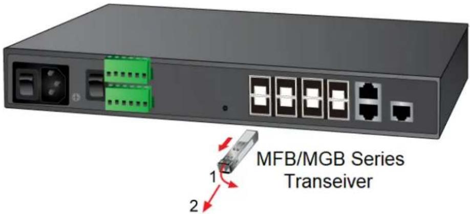
Figure 2-11: How to Pull Out the SFP Transceiver Module

Never pull out the module without lifting up the lever of the module and turning it to a horizontal position. Directly pulling out the module could damage the module and the SFP module slot of the Managed Metro Switch.
3. SWITCH MANAGEMENT
This chapter explains the methods that you can use to configure management access to the Managed Metro Switch. It describes the types of management applications and the communication and management protocols that deliver data between your management device (workstation or personal computer) and the system. It also contains information about port connection options.
This chapter covers the following topics:
- Requirements
■ Management Access Overview
■ Remote Telnet Access
■ Web Management Access
■ SNMP Access
■ Standards, Protocols, and Related Reading
3.1 Requirements
■ Workstations running Windows XP/2003/2008/2012/Vista/7/8/10, MAC OS X or later, Linux, UNIX, or other platforms are compatible with TCP/IP protocols.
■ Workstations are installed with Ethernet NIC (Network Interface Card)
■ Serial Port Connection (Terminal)
The above workstations come with COM port (DB9) or USB-to-RS232 converter.
The above workstations have been installed with terminal emulator, such as Tera Term, PuTTY or Hyper Terminal included in Windows XP/2003.
Serial cable -- one end is attached to the RS232 serial port, while the other end to the console port of the Managed Metro Switch.
■ Ethernet Port Connection
Network cables -- Use standard network (UTP) cables with RJ45 connectors.
The above PC is installed with Web browser.

It is recommended to use Internet Explorer 8.0 or above to access the Managed Metro Switch. If the Web interface of the Managed Metro Switch is not accessible, please turn off the antivirus software or firewall and then try it again.
3.2 Management Access Overview
The Managed Metro Switch gives you the flexibility to access and manage it using any or all of the following methods:
■ Remote Telnet Interface
■ Web browser Interface
■ An external SNMP-based network management application
The remote Telnet and Web browser interfaces are embedded in the Managed Metro Switch software and are available for immediate use. Each of these management methods has their own advantages. Table 3-1 compares the three management methods.
| Method | Advantages | Disadvantages |
| Console | No IP address or subnet neededText-basedTelnet functionality and HyperTerminal built into Windows95/98/NT/2000/ME/XP operating systemsProcommPlus, putty, tera termSecure | Must be near the switch or use dial-up connectionNot convenient for remote usersModem connection may prove to be unreliable or slow |
| Remote Telnet | Text-basedTelnet functionality built into Windows XP/2003, Vista, Windows 7 operating systemsCan be accessed from any location | Security can be compromised (hackers need only know the IP address) |
| Web Browser | Ideal for configuring the switch remotelyCompatible with all popular browsersCan be accessed from any locationMost visually appealing | Security can be compromised (hackers need only know the IP address and subnet mask)May encounter lag times on poor connections |
| SNMP Agent | Communicates with switch functions at the MIB levelBased on open standards | Requires SNMP manager softwareLeast visually appealing of all three methodsSome settings require calculationsSecurity can be compromised (hackers need only know the community name) |
Table 3-1: Management Methods Comparison
3.3 CLI Mode Management
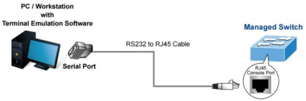
There are two ways for CLI mode management, one is remote telnet and the other operated from console port. Remote telnet is an IP-based protocol and console port is for user to operate the Managed Metro Switch locally only; however, their operations are the same.
The command line user interface is for performing system administration, such as displaying statistics or changing option settings. When this method is used, you can access the Managed Metro Switch remote telnet interface from personal computer, or workstation in the same Ethernet environment as long as you know the current IP address of the Managed Metro Switch.
flowchart
graph LR
    A["PC / Workstation with Terminal Emulation Software"] --> B["Serial Port"]
    B --> C["RS232 to RJ45 Cable"]
    C --> D["Managed Switch"]
    D --> E["RJ45 Console Port"]
Direct Access
Direct access to the administration console is achieved by directly connecting a terminal or a PC equipped with a terminal-emulation program (such as HyperTerminal, ProcommPlus, putty, tera term) to the Managed Metro Switch console (serial) port. When using this management method, a straight DB9 RS-232 cable is required to connect the switch to the PC. After making this connection, configure the terminal-emulation program to use the following parameters:
The default parameters are:
■ 115200 bps baud rate
■ 8 data bits
■ No parity
■ 1 stop bit
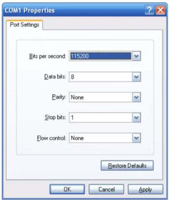
You can change these settings, if desired, after you log on. This management method is often preferred because you can remain connected and monitor the system during system reboots. Also, certain error messages are sent to the serial port, regardless of the interface through which the associated action was initiated. A Macintosh or PC attachment can use any terminal-emulation program for connecting to the terminal serial port. A workstation attachment under UNIX can use an emulator
Remote Telnet
In Windows system, you may click "Start" and then choose "Accessories" and "Command Prompt". Please input "telnet 192.168.0.100" and press "enter" from your keyboard. You will see the following screen appears as Figure 3-2 shows.
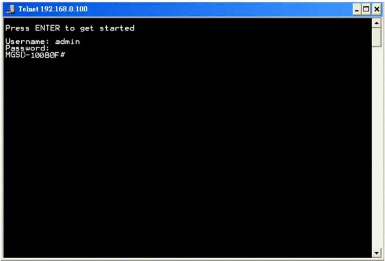
Figure 3-1: Remote Telnet Interface Main Screen of Managed Metro Switch
3.4 Web Management
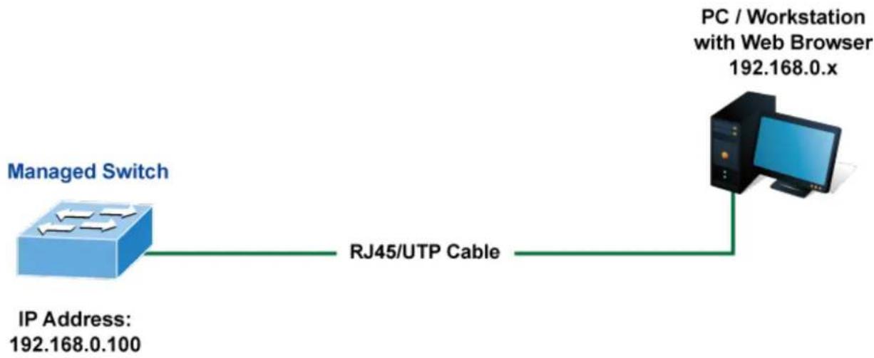
The Managed Metro Switch offers management features that allow users to manage the Managed Metro Switch from anywhere on the network through a standard browser such as Microsoft Internet Explorer. After you set up your IP address for the Managed Metro Switch, you can access the Managed Metro Switch's Web interface applications directly in your Web browser by entering the IP address of the Managed Metro Switch.
flowchart
graph LR
    A["Managed Switch"] -->|IP Address: 192.168.0.100| B["RJ45/UTP Cable"]
    B --> C["PC / Workstation with Web Browser 192.168.0.x"]
Figure 3-2: Web Management
You can then use your Web browser to list and manage the Managed Metro Switch configuration parameters from one central location; the Web Management requires Microsoft Internet Explorer 8.0 or later.
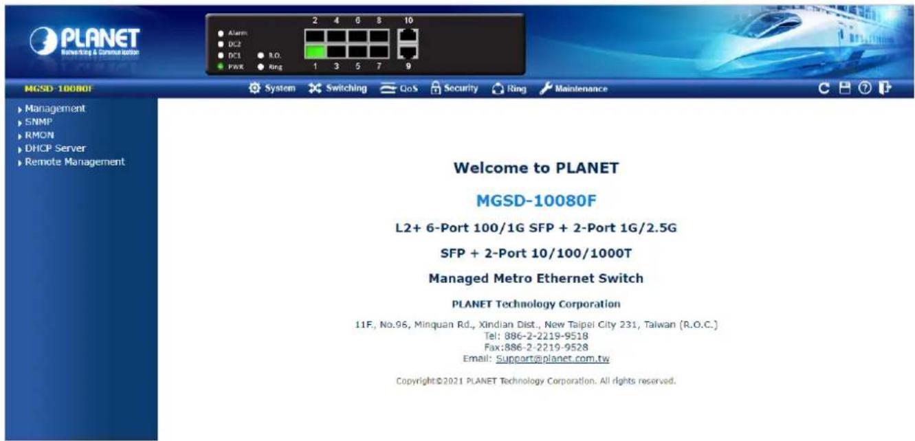
Figure 3-3: Web Main Screen of Managed Metro Switch
3.5 SNMP-based Network Management
You can use an external SNMP-based application to configure and manage the Managed Metro Switch, such as SNMP Network Manager, HP Openview Network Node Management (NNM) or What's Up Gold. This management method requires the SNMP agent on the Managed Metro Switch and the SNMP Network Management Station to use the same community string. This management method, in fact, uses two community strings: the get community string and the set community string.
If the SNMP Network Management Station only knows the set community string, it can read and write to the MIBs. However, if it only knows the get community string, it can only read MIBs. The default gets and sets community strings for the Managed Metro Switch are public.
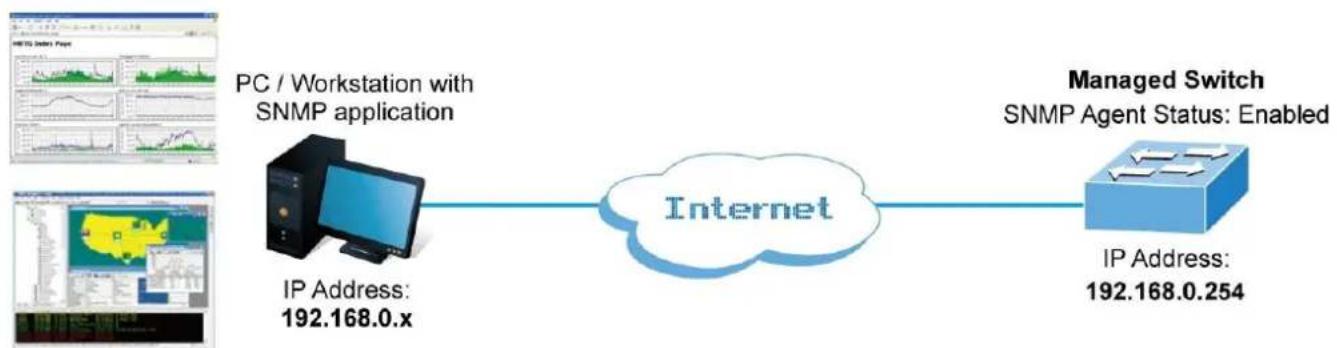
flowchart
graph LR
    A["IP Address: 192.168.0.x"] --> B["Internet"]
    C["PC / Workstation with SNMP application"] --> B
    D["Managed Switch\nSNMP Agent Status: Enabled"] --> B
    B --> E["IP Address: 192.168.0.254"]
Figure 3-4: SNMP Management
3.6 PLANET Smart Discovery Utility
To easily list the Managed Metro Switch in your Ethernet environment, the Planet Smart Discovery Utility from user's manual CD-ROM is an ideal solution. The following install instructions guide you to running the Planet Smart Discovery Utility.
- Open the Planet Smart Discovery Utility in administrator PC.
- Run this utility and the following screen appears.
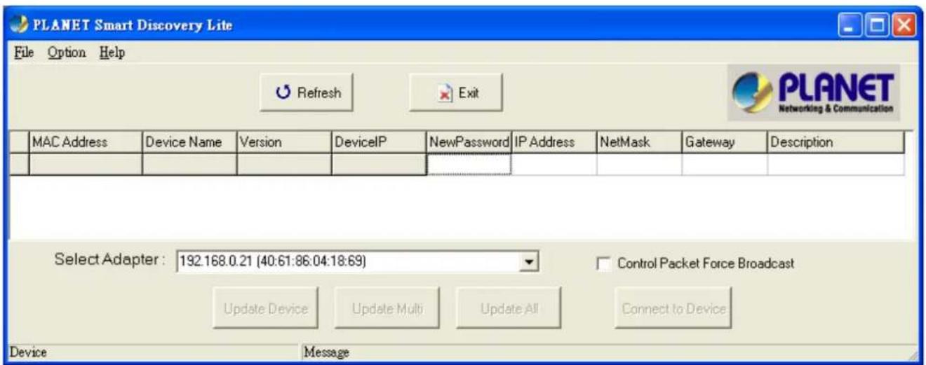
Figure 3-5: PLANET Smart Discovery Utility Screen

If there are two LAN cards or above in the same administrator PC, choose a different LAN card by using the "Select Adapter" tool.
- Press the "Refresh" button for the currently connected devices in the discovery list as the screen is shown as follows.
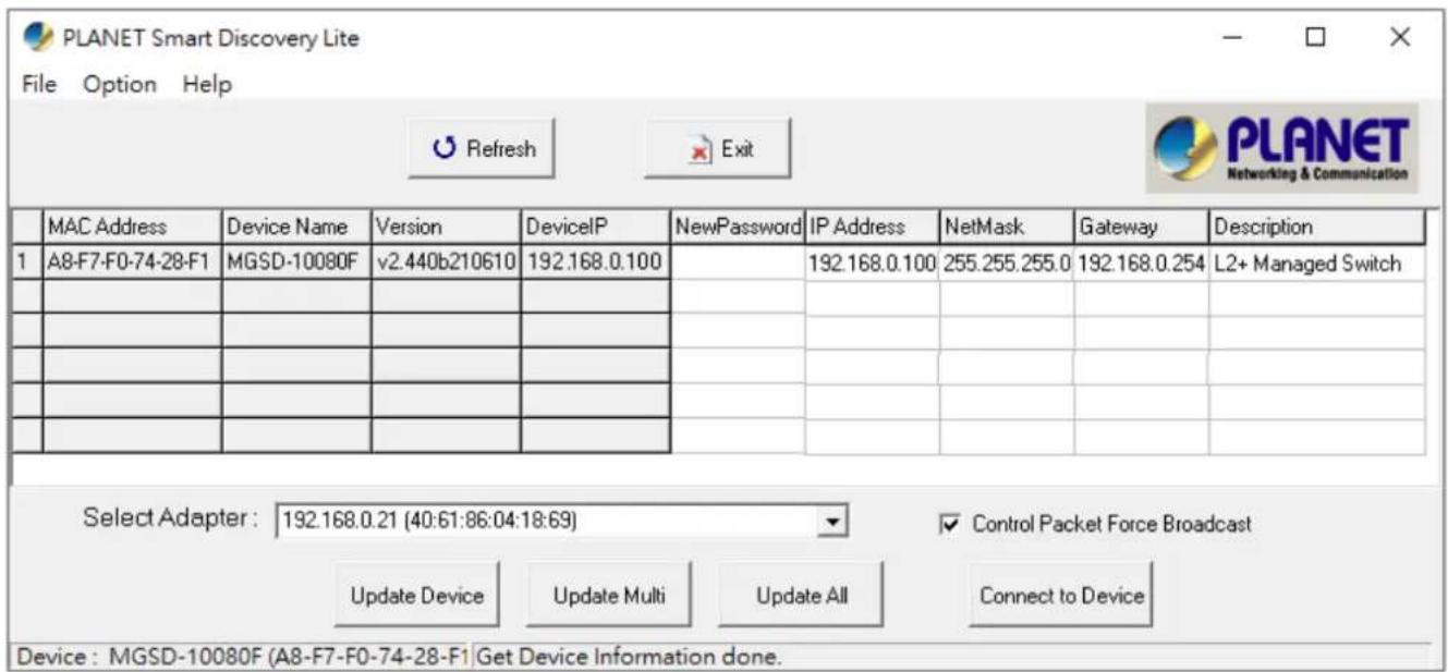
Figure 3-6: Planet Smart Discovery Utility Screen
- This utility shows all the necessary information from the devices, such as MAC Address, Device Name, firmware version and Device IP Subnet address. A new password, IP Subnet address and description can be assigned to the devices.
- After setup is completed, press the "Update Device", "Update Multi" or "Update All" button to take effect. The meanings of the 3 buttons above are shown below:
■ Update Device: Use the current setting on one single device.
■ Update Multi: Use the current setting on choose multi-devices.
■ Update All: Use the current setting on whole devices in the list.
The same functions mentioned above also can be found in "Option" tools bar.
- To click the "Control Packet Force Broadcast" function, it allows new setting value to be assigned to the Web Smart Switch under a different IP subnet address.
- Press the "Connect to Device" button and then the Web login screen appears in Figure 3-3.
- Press the "Exit" button to shut down Planet Smart Discovery Utility.
This section introduces the configuration and functions of the Web-based management.
About Web-based Management
The Managed Metro Switch offers management features that allow users to manage the Managed Metro Switch from anywhere on the network through a standard browser such as Microsoft Internet Explorer.
The Managed Metro Switch can be configured through an Ethernet connection, making sure the manager PC must be set on the same IP subnet address as the Managed Metro Switch.
For example, the default IP address of the Managed Metro Switch is 192.168.0.100, then the manager PC should be set at 192.168.0.x (where x is a number between 1 and 254, except 100), and the default subnet mask is 255.255.255.0.
If you have changed the default IP address of the Managed Metro Switch to 192.168.1.1 with subnet mask 255.255.255.0 via console, then the manager PC should be set at 192.168.1.x (where x is a number between 2 and 254) to do the relative configuration on manager PC.
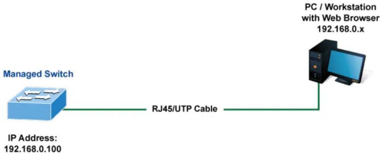
flowchart
graph LR
    A["Managed Switch"] -->|IP Address: 192.168.0.100| B["RJ45/UTP Cable"]
    B --> C["PC / Workstation with Web Browser 192.168.0.x"]
Figure 4-1-1: Web Management
■ Logging on the Managed Metro Switch
- Use Internet Explorer 8.0 or above Web browser. Enter the factory-default IP address to access the Web interface. The factory-default IP Address as following:
https://192.168.0.100
- When the following login screen appears, please enter the default username "admin" with password "admin" (or the username/password you have changed via console) to login the main screen of Managed Metro Switch. The login screen in Figure 4-1-2 appears.
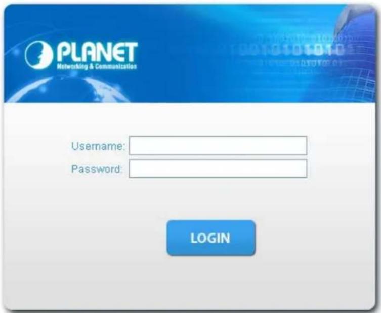
Figure 4-1-2: Login Screen
Default User name: admin
Default Password: admin
After entering the username and password, the main screen appears as Figure 4-1-3.
![PLANET Networking & Communication MGSD-10080F Management SNMP RMON DHCP Server Remote Management 2 4 6 8 10 Alarm DC2 DC3 R.O. FWR Ring 1 3 5 7 9 System Switching GoS Security Ring Maintenance Welcome to PLANET MGSD-10080F L2+ 6-Port 100/1G SFP + 2-Port 1G/2.5G SFP + 2-Port 10/100/1000T Managed Metro Ethernet Switch PLANET Technology Corporation 11F, No.96, Minquan Rd., Xindian Dist., New Taipei City 231, Taiwan [R.O.C.] Tel: 886-2-2219-9518 Fax:886-2-2219-9528 Email: Support@planet.com.tw Copyright©2021 PLANET Technology Corporation. All rights reserved.](/content/2026/05/900973/images/9ca2167c008135d16c3a3edb2c2e95123bbdd3cb4d89deb94de64795da7b5817.jpg)
Figure 4-1-3: Web Main Screen of Managed Metro Switch
Now, you can use the Web management interface to continue the switch management or manage the Managed Metro Switch by Web interface. The Switch Menu on the left of the web page let you access all the commands and statistics the Managed Metro Switch provides.

It is recommended to use Internet Explore 8.0 or above to access Managed Metro Switch.
The changed IP address takes effect immediately after clicking on the Apply button. You need to use the new IP address to access the Web interface.

For security reason, please change and memorize the new password after this first setup.
■ Only accept command in lowercase letter under web interface.
4.1 Main Web page
The Managed Metro Switch provides a Web-based browser interface for configuring and managing it. This interface allows you to access the Managed Metro Switch using the Web browser of your choice. This chapter describes how to use the Managed Metro Switch's Web browser interface to configure and manage it.
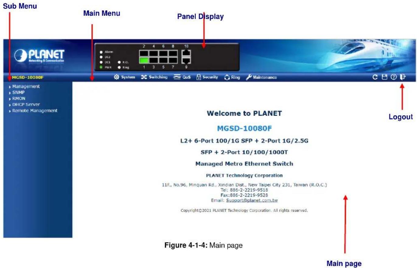
Panel Display
The web agent displays an image of the Managed Metro Switch's ports. The Mode can be set to display different information for the ports, including Link up or Link down. Clicking on the image of a port opens the Port Statistics page.
The port states are illustrated as follows:
State
RJ45 Ports
SFP Ports
Disabled


Down


Link


Main Menu
Using the onboard web agent, you can define system parameters, manage and control the Managed Metro Switch, and all its ports, or monitor network conditions. Via the Web-Management, the administrator can set up the Managed Metro Switch by selecting the functions those listed in the Main Function. The screen in Figure 4-1-5 appears.

System

Switching

QoS

Security

Ring

Maintenance
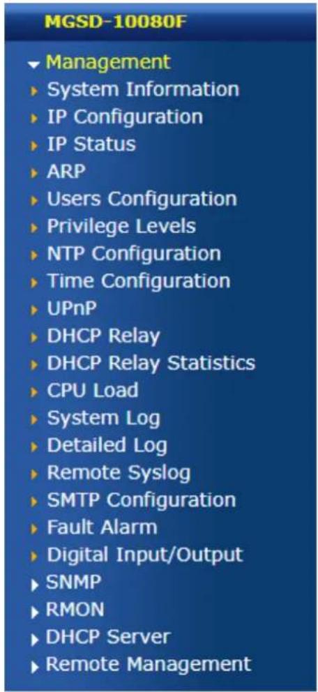
Figure 4-1-5: Managed Metro Switch Main Functions Menu
4.2 System
Use the System menu items to display and configure basic administrative details of the Managed Metro Switch. Under the System, the following topics are provided to configure and view the system information. This section has the following items:
System Information The Managed Metro Switch system information is provided here.
IP Configuration Configure the IPv4/IPv6 interface and IP routes of the Managed Metro Switch on this page.
IP Status This page displays the status of the IP protocol layer. The status is defined by the IP interfaces, the IP routes and the neighbor cache (ARP cache) status.
■ ARP Table This page provide aging time setting and ARP table display.
■ Users Configuration This page provides an overview of the current users. Currently the only way to login as another user on the web server is to close and reopen the browser.
■ Privilege Levels This page provides an overview of the privilege levels.
NTP Configuration Configure NTP server on this page.
Time Configuration Configure time parameter on this page.
■ UPnP Configure UPnP on this page.
DHCP Relay Configure DHCP Relay on this page.
DHCP Relay Statistics This page provides statistics for DHCP relay.
CPU Load This page displays the CPU load, using an SVG graph.
System Log The system log information of the Managed Metro Switch system is provided here.
Detailed Log The detailed log information of the Managed Metro Switch system is provided here.
■ Remote Syslog Configure remote syslog on this page.
■ SMTP Configuration Configure SMTP parameters on this page.
Fault Alarm Configuration fault alarm on this page.
Digital Input/Output Configuration digital input and output on this page.
SNMP Configure SNMP parameters on this page
■ RMON Configure the RMON parameters on this page
DHCP server Configure the DHCP server on this page
Remote Management Configure Remote NMS Configuration settings on this page.
4.2.1 Management
4.2.1.1 System Information
The System Information page provides information for the current device information. System Information page helps a switch administrator to identify the hardware MAC address, software version and system uptime. The screen in Figure 4-2-1 appears.
System Information
| System | |
| Contact Name Location | Default Contact MGSD-10080F Default Location |
| Hardware | |
| MAC Address | a8-f7-f0-74-28-f1 |
| Power Status | DC 1 :OFF DC 2 :OFF AC PWR :ON |
| Time | |
| System Date | 1970-01-01 Thu 07:22:52+00:00 |
| System Uptime | 0d 07:22:52 |
| Software | |
| Software Version | v2.440b210610 |
| Software Date | 2021-06-10T15:29:10+08:00 |
Auto-refresh □ Refresh
Figure 4-2-1: System Information Page Screenshot
The page includes the following fields:
| Object Description | |
| • Contact | The system contact configured in SNMP | System Information | System Contact. |
| • Name | The system name configured in SNMP | System Information | System Name. |
| • Location | The system location configured in SNMP | System Information | System Location. |
| • MAC Address | The MAC Address of this Managed Metro Switch. |
| • Power Status | The status of power input. |
| • System Date | The current (GMT) system time and date. The system time is obtained through the configured NTP Server, if any. |
| • System Uptime | The period of time the device has been operational. |
| • Software Version | The software version of the Managed Metro Switch. |
| • Software Date | The date when the Managed Metro Switch software was produced. |
Buttons
Auto-refresh ☐: Check this box to refresh the page automatically. Automatic refresh occurs every 3 seconds.
Refresh
Click to refresh the page; any changes made locally will be undone.
4.2.1.2 IP Configuration
The IP Configuration includes the IP Configuration, IP Interface and IP Routes. The configured column is used to view or change the IP configuration. The maximum number of interfaces supported is 128 and the maximum number of routes is 32.
The screen in Figure 4-2-2 appears.
IP Configuration

IP Interfaces
| Delete | VLAN | DHCPv4 | IPv4 | DHCPv6 | IPv6 | |||||||||||
| Enable | Client ID | Hostname | Fallback | Current Lease | Address | Mask Length | Enable | Rapid Commit | Current Lease | Address | Mask Length | |||||
| Type | IFMac | ASCII | HEX | |||||||||||||
| 1 | Auto | Part 1 | 192 168 6 100 | 24 | ||||||||||||
Add Interface
Delete Network Mask Length Gateway Next Hop VLAN
Add Route
Apply Reset
IP Routes
Figure 4-2-2: IP Configuration Page Screenshot
The current column is used to show the active IP configuration.
| Object Description | |||
| IP Configurations | Domain Name | Configure the Switch Domain Name | |
| Mode | Configure whether the IP stack should act as a Host or a Router. In Host mode, IP traffic between interfaces will not be routed. In Router mode traffic is routed between all interfaces. | ||
| DNS Server | This setting controls the DNS name resolution done by the switch.The following modes are supported:No DNS serverNo DNS server will be used..Configure IPv4 or IPv6Explicitly specify the name of local domain.Make sure the configured domain name meets your organization's given domain.From any DHCPv6 interfacesThe first domain name offered from a DHCPv6 lease to a DHCPv6-enabled interface will be used.From this DHCPv6 interfaceSpecify from which DHCPv6-enabled interface a provided domain name should be preferred. | ||
| DNS Proxy | When DNS proxy is enabled, system will relay DNS requests to the currently configured DNS server, and reply as a DNS resolver to the | ||
| client devices on the network. | |||
| IP Interface | Delete | Select this option to delete an existing IP interface. | |
| VLAN | The VLAN associated with the IP interface. Only ports in this VLAN will be able to access the IP interface. This field is only available for input when creating a new interface. | ||
| IPv4 DHCP | Enabled | Enable the DHCP client by checking this box. | |
| Fallback | The number of seconds for trying to obtain a DHCP lease. | ||
| Current Lease | For DHCP interfaces with an active lease, this column shows the current interface address, as provided by the DHCP server. | ||
| IPv4 Address | Provide the IP address of this Managed Metro Switch in dotted decimal notation. | ||
| Mask Length | |||
| DHCPv6 | Enable | Enable the DHCPv6 client by checking this box. If this option is enabled, the system will configure the IPv6 address of the interface using the DHCPv6 protocol | |
| Rapid Commit | Enable the DHCPv6 Rapid-Commit option by checking this box. If this option is enabled, the DHCPv6 client terminates the waiting process as soon as a Reply message with a Rapid Commit option is received.This option is only manageable when DHCPv6 client is enabled. | ||
| Current Lease | For DHCPv6 interface with an active lease, this column shows the interface address provided by the DHCPv6 server | ||
| IPv6 Address | Provide the IP address of this Managed Metro Switch. An IPv6 address is in 128-bit records represented as eight fields of up to four hexadecimal digits with a colon separating each field (:) | ||
| Mask Length | |||
| IP Routes | Delete | Select this option to delete an existing IP route. | |
| Network | The destination IP network or host address of this route. Valid format is dotted decimal notation or a valid IPv6 notation. A default route can use the value0.0.0.0or IPv6::notation. | ||
| Mask Length | The destination IP network or host mask, in number of bits (prefix length). | ||
| Gateway | The IP address of the IP gateway. Valid format is dotted decimal notation or a valid IPv6 notation. Gateway and Network must be of the same type. | ||
| Next Hop VLAN | The VLAN ID (VID) of the specific IPv6 interface associated with the gateway. | ||
Buttons
Add Interface
Click to add a new IP interface. A maximum of 128 interfaces are supported.
Add Route
: Click to add a new IP route. A maximum of 32 routes are supported.
Apply
: Click to apply changes.
Reset
: Click to undo any changes made locally and revert to previously saved values.
4.2.1.3 IP Status
IP Status displays the status of the IP protocol layer. The status is defined by the IP interfaces, the IP routes and the neighbor cache (ARP cache) status. The screen in Figure 4-2-3 appears.
Auto-refresh □ Refresh
IP Interfaces
| Interface | Type | Address | Status |
| VLAN1 | LINK | a8-f7-f0-74-28-f1 | |
| VLAN1 | IPv4 | 10.1.20.63/24 | |
| VLAN1 | IPv6 | fe80::aaf7::f0ff:fe74:28f1/64 |
IPv4 Routes
| Network | Gateway | Status |
| 10.1.20.0/24 | VLAN 1 |
IPv6 Routes
| Network | Gateway | Status |
Neighbour cache
| IP Address | Link Address |
Figure 4-2-3: IP Status Page Screenshot
The page includes the following fields:
| Object Description | ||
| • IP Interfaces | Interface | The name of the interface. |
| Type | The address type of the entry. This may beLINK or IPv4. | |
| Address | The current address of the interface (of the given type). | |
| Status | The status flags of the interface (and/or address). | |
| • IPv4/v6 Routes | Network | The destination IP network or host address of this route. |
| Gateway | The gateway address of this route. | |
| Status | The status flags of the route. | |
| • Neighbor Cache | IP Address | The IP address of the entry. |
| Link Address | The Link (MAC) address for which a binding to the IP address given exists. | |
Buttons
Auto-refresh ☐ : Check this box to refresh the page automatically. Automatic refresh occurs every 3 seconds.
Refresh
Click to refresh the page.
4.2.1.4 ARP Table
This page provides an overview of the current ARP table, also allows to configure Aging time setting on this page. After setup is completed, press the "Apply" button to take effect, the screen in Figure 4-2-4 appears.
ARP Table Configuration
Aging Configuration
| Disable Automatic Aging | ☐ |
| Aging Time | 300 seconds |
Apply
Reset
ARP Table
| IP Address | Link Address |
| 10.1.20.30 | VLAN1:10:c3:7b:49:1a:4d |
| 10.1.20.77 | VLAN1:18:31:bf:92:0a:8d |
| 10.1.20.76 | VLAN1:10:c3:7b:49:30:6e |
| 10.1.20.254 | VLAN1:a8:f7:e0:5c:54:bf |
| 10.1.20.75 | VLAN1:c8:9c:dc:ec:d6:dd |
Refresh
Clear
Figure 4-2-4: ARP Table Configuration Page Screenshot
The page includes the following fields:
| Object Description | |
| • Disable Automatic Aging | Provide disable MAC learning function by enable this function. |
| • Aging time | Allow to configure the aging time setting and the available range is 10 to 1000000 seconds. Default is 300 seconds. |
Buttons
Apply
: Click to apply changes.
Reset
: Click to undo any changes made locally and revert to previously saved values.
Refresh
Click to refresh the page.
Clear
: Click to clear the ARP table information.
4.2.1.5 Users Configuration
This page provides an overview of the current users. Currently the only way to login as another user on the web server is to close and reopen the browser. After setup is completed, press the "Apply" button to take effect. Please login web interface with new user name and password; the screen in Figure 4-2-5 appears.
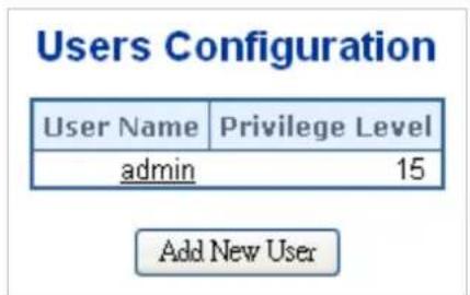
Figure 4-2-5: Users Configuration Page Screenshot
The page includes the following fields:
| Object Description | |
| User Name | The name identifying the user. This is also a link to Add/Edit User. |
| Privilege Level | The privilege level of the user.The allowed range is0to15. If the privilege level value is 15, it can access all groups, i.e. that is granted the full control of the device. But other values need to refer to each group privilege level. User's privilege should be the same or greater than the group privilege level to have the access to that group.By default setting, most groups privilege level 5 has the read-only access and privilege level 10 has the read-write access. And the system maintenance (software upload, factory defaults and etc.) needs user privilege level 15.Generally, the privilege level 15 can be used for an administrator account, privilege level 10 for a standard user account and privilege level 5 for a guest account. |
Buttons
Add New User
Click to add a new user.
Add / Edit User
This page configures a user – add, edit or delete user.
Add User
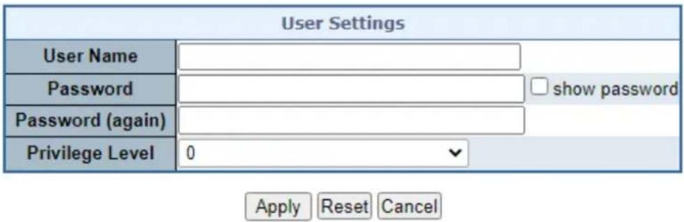
Figure 4-2-6: Add / Edit User Configuration Page Screenshot
The page includes the following fields:
| Object Description | |
| •Username | A string identifying the user name that this entry should belong to. The allowed string length is 1 to 31. The valid user name is a combination of letters, numbers and underscores. |
| •Password | The password of the user. The allowed string length is 0 to 31. |
| •Password (again) | Please enter the user's new password here again to confirm. |
| •Privilege Level | The privilege level of the user.The allowed range is 0 to 15. If the privilege level value is 15, it can access all groups, i.e. that is granted the fully control of the device. But others value need to refer to each group privilege level. User's privilege should be same or greater than the group privilege level to have the access of that group.By default setting, most groups privilege level 5 has the read-only access and privilege level 10 has the read-write access. And the system maintenance (software upload, factory defaults and etc.) needs user privilege level 15.Generally, the privilege level 15 can be used for an administrator account, privilege level 10 for a standard user account and privilege level 5 for a guest account. |
Buttons
Apply
Click to apply changes.
Reset
Click to undo any changes made locally and revert to previously saved values.
Cancel
: Click to undo any changes made locally and return to the Users.
Delete User
Delete the current user. This button is not available for new configurations (Add new user).
Once the new user is added, the new user entry is shown on the Users Configuration page.
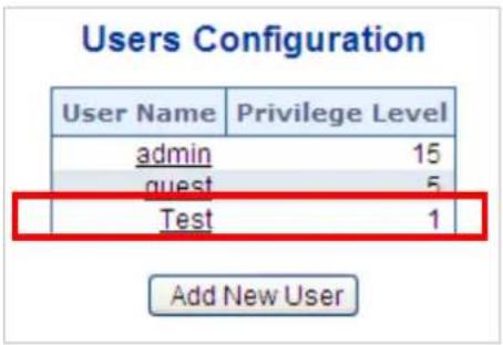
Figure 4-2-7: User Configuration Page Screenshot

If you forget the new password after changing the default password, please press the "Reset" button on the front panel of the Managed Metro Switch for over 5 seconds and then release it. The current setting including VLAN will be lost and the Managed Metro Switch will restore to the default mode.
4.2.1.6 Privilege Levels
This page provides an overview of the privilege levels. After setup is completed, please press the "Apply" button to take effect. Please login web interface with new user name and password and the screen in Figure 4-2-8 appears.
Privilege Level Configuration
| Group Name | Privilege Levels | ||||
| Configuration Read-only | Configuration/Execute Read/write | Status/Statistics Read-only | Status/Statistics Read/write | ||
| Aggregation | 5 ▼ | 10 ▼ | 5 ▼ | 10 ▼ | |
| Diagnostics | 5 ▼ | 10 ▼ | 5 ▼ | 10 ▼ | |
| DIDO | 5 ▼ | 10 ▼ | 5 ▼ | 10 ▼ | |
| ERPS | 5 ▼ | 10 ▼ | 5 ▼ | 10 ▼ | |
| ETH_LINK_OAM | 5 ▼ | 10 ▼ | 5 ▼ | 10 ▼ | |
| Firmware | 5 ▼ | 10 ▼ | 5 ▼ | 10 ▼ | |
| FRR | 5 ▼ | 10 ▼ | 5 ▼ | 10 ▼ | |
| IP | 5 ▼ | 10 ▼ | 5 ▼ | 10 ▼ | |
| IPMC_Snooping | 5 ▼ | 10 ▼ | 5 ▼ | 10 ▼ | |
| LACP | 5 ▼ | 10 ▼ | 5 ▼ | 10 ▼ | |
| LLDP | 5 ▼ | 10 ▼ | 5 ▼ | 10 ▼ | |
| Loop_Protect | 5 ▼ | 10 ▼ | 5 ▼ | 10 ▼ | |
| MAC_Table | 5 ▼ | 10 ▼ | 5 ▼ | 10 ▼ | |
| MEP | 5 ▼ | 10 ▼ | 5 ▼ | 10 ▼ | |
| Miscellaneous | 15 ▼ | 15 ▼ | 15 ▼ | 15 ▼ | |
| MVR | 5 ▼ | 10 ▼ | 5 ▼ | 10 ▼ | |
| NTP | 5 ▼ | 10 ▼ | 5 ▼ | 10 ▼ | |
| port_backup | 5 ▼ | 10 ▼ | 5 ▼ | 10 ▼ | |
| Ports | 5 ▼ | 10 ▼ | 1 ▼ | 10 ▼ | |
| Private_VLANs | 5 ▼ | 10 ▼ | 5 ▼ | 10 ▼ | |
| QoS | 5 ▼ | 10 ▼ | 5 ▼ | 10 ▼ | |
| Security_access | 10 ▼ | 10 ▼ | 5 ▼ | 10 ▼ | |
| Security_network | 5 ▼ | 10 ▼ | 5 ▼ | 10 ▼ | |
| Spanning_Tree | 5 ▼ | 10 ▼ | 5 ▼ | 10 ▼ | |
| System | 5 ▼ | 10 ▼ | 1 ▼ | 10 ▼ | |
| Traceroute | 5 ▼ | 10 ▼ | 5 ▼ | 10 ▼ | |
| UPnP | 5 ▼ | 10 ▼ | 5 ▼ | 10 ▼ | |
| VLAN_Translation | 5 ▼ | 10 ▼ | 5 ▼ | 10 ▼ | |
| VLANs | 5 ▼ | 10 ▼ | 5 ▼ | 10 ▼ | |
| Voice_VLAN | 5 ▼ | 10 ▼ | 5 ▼ | 10 ▼ | |
Apply Reset
Figure 4-2-8: Privilege Levels Configuration Page Screenshot
The page includes the following fields:
| Object Description | |
| • Group Name | The name identifying the privilege group. In most cases, a privilege level group consists of a single module (e.g. LACP, RSTP or QoS), but a few of them contain more than one. The following description defines these privilege level groups in details:■ System: Contact, Name, Location, Timezone, Log.■ Security: Authentication, System Access Management, Port (contains Dot1x port, MAC based and the MAC Address Limit), ACL, HTTPS, SSH, ARP Inspection and IP source guard.■ IP: Everything except 'ping'.■ Port: Everything except 'VeriPHY'.■ Diagnostics: 'ping' and 'VeriPHY'.■ Maintenance: CLI- System Reboot, System Restore Default, System Password, Configuration Save, Configuration Load and Firmware Load. Web- Users, Privilege Levels and everything in Maintenance.■ Debug: Only present in CLI. |
| • Privilege Level | Every privilege level group has an authorization level for the following sub groups:■ Configuration read-only■ Configuration/execute read-write■ Status/statistics read-only■ Status/statistics read-write (e.g. for clearing of statistics).User Privilege should be same or greater than the authorization Privilege level to have the access to that group. |
Buttons
Apply
: Click to apply changes.
Reset
: Click to undo any changes made locally and revert to previously saved values.
4.2.1.7 NTP Configuration
Configure NTP on this page. NTP is an acronym for Network Time Protocol, a network protocol for synchronizing the clocks of computer systems. NTP uses UDP (data grams) as transport layer. You can specify NTP Servers. The NTP Configuration screen in Figure 4-2-9 appears.
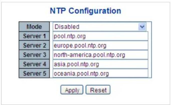
Figure 4-2-9: NTP Configuration Page Screenshot
The page includes the following fields:
| Object Description | |
| • Mode | Indicates the NTP mode operation. Possible modes are:■ Enabled: Enable NTP mode operation. When enabling NTP mode operation, the agent forward and transfer NTP messages between the clients and the server when they are not on the same subnet domain.■ Disabled: Disable NTP mode operation. |
| • Server # | Provide the NTP IPv4 or IPv6 address of this switch. IPv6 address is in 128-bit records represented as eight fields of up to four hexadecimal digits with a colon separating each field (:).For example, 'fe80::215:c5ff:fe03:4dc7'. The symbol '::' is a special syntax that can be used as a shorthand way of representing multiple 16-bit groups of contiguous zeros, but it can only appear once. It also uses a legal IPv4 address like '::192.1.2.34'. |
Buttons
: Click to apply changes.
: Click to undo any changes made locally and revert to previously saved values.


4.2.1.7.1 System Time Correction Manually
Configure NTP on this page. NTP is an acronym for Network Time Protocol, a network protocol for synchronizing the clocks of computer systems. NTP uses UDP (data grams) as transport layer. You can specify NTP Servers. The NTP Configuration screen in Figure 4-2-10 appears.
System Time Correction Manually
| User Manually | Enable | |
| Year | 1970 | (1970 ~ 2037) |
| Month | 1 | (1 ~ 12) |
| Day | 1 | (1 ~ 31) |
| Hour | 0 | (0 ~ 23) |
| Minute | 0 | (0 ~ 59) |
| Second | 0 | (0 ~ 59) |
Apply Reset
Figure 4-2-10: System time correction Manually Page Screenshot
The page includes the following fields:
| Object Description | |
| User Manually | Indicates the NTP mode as manual operation. Possible modes are:■ Enabled: Enable NTP manual mode operation. When enabling NTP user manually mode operation, the system time will follow the date setting.■ Disabled: Disable NTP user manual mode operation. |
| Date | If enable the user manually , Switch can set the Year / Mouth / Day/ Hour / Minute / Second in this page |
Buttons
Apply
: Click to apply changes.
Reset
: Click to undo any changes made locally and revert to previously saved values.
4.2.1.8 Time Configuration
Configure Time Zone on this page. A Time Zone is a region that has a uniform standard time for legal, commercial, and social purposes. It is convenient for areas in close commercial or other communication to keep the same time, so time zones tend to follow the boundaries of countries and their subdivisions. The Time Zone Configuration screen in Figure 4-2-11 appears
Time Zone Configuration
| Time Zone Configuration | |
| Time Zone | (UTC) Coordinated Universal Time ▼ |
| Hours | 0 ▼ |
| Minutes | 0 ▼ |
| Acronym | (0 - 16 characters) |
Daylight Saving Time Configuration

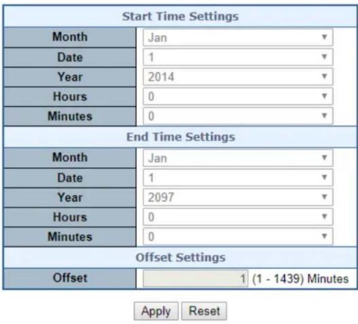
Figure 4-2-11: Time Configuration Page Screenshot
The page includes the following fields:
| Object Description | |
| • Time Zone | Lists various Time Zones worldwide. Select appropriate Time Zone from the drop-down and click Save to set. |
| • Acronym | User can set the acronym of the time zone. This is a User configurable acronym to identify the time zone. ( Range: Up to 16 characters ) |
| • Daylight Saving Time | This is used to set the clock forward or backward according to the configurations set below for a defined Daylight Saving Time duration. Select 'Disable' to disable the Daylight Saving Time configuration. Select 'Recurring' and configure theDaylight Saving Time duration to repeat the configuration every year. Select 'Non-Recurring' and configure the Daylight Saving Time duration for single time configuration. (Default: Disabled). |
| • Start Time Settings | • Week - Select the starting week number.• Day - Select the starting day.• Month - Select the starting month.• Hours - Select the starting hour.• Minutes - Select the starting minute. |
| • End Time Settings | • Week - Select the ending week number.• Day - Select the ending day.• Month - Select the ending month.• Hours - Select the ending hour.• Minutes - Select the ending minute |
| • Offset Settings | Enter the number of minutes to add during Daylight Saving Time. (Range: 1 to 1440) |
Buttons
Apply
: Click to apply changes.
Reset
: Click to undo any changes made locally and revert to previously saved values.
4.2.1.9 UPnP
Configure UPnP on this page. UPnP is an acronym for Universal Plug and Play. The goals of UPnP are to allow devices to connect seamlessly and to simplify the implementation of networks in the home (data sharing, communications, and entertainment) and in corporate environments for simplified installation of computer components. The UPnP Configuration screen in Figure 4-2-12 appears.
UPnP Configuration
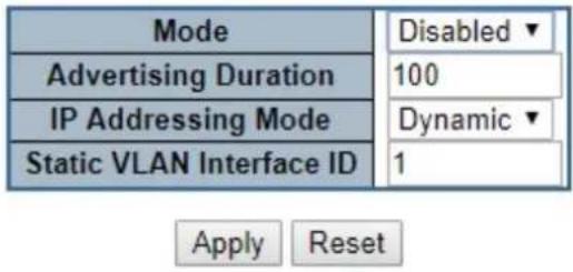
Figure 4-2-12: UPnP Configuration Page Screenshot
The page includes the following fields:
| Object Description | |
| • Mode | Indicates the UPnP operation mode. Possible modes are:■ Enabled: Enable UPnP mode operation.■ Disabled: Disable UPnP mode operation.When the mode is enabled, two ACEs are added automatically to trap UPnP related packets to CPU. The ACEs are automatically removed when the mode is disabled. |
| • Advertising Duration | The duration, carried in SSDP packets, is used to inform a control point or control points how often it or they should receive a SSDP advertisement message from this switch. If a control point does not receive any message within the duration, it will think that the switch no longer exists. Due to the unreliable nature of UDP, in the standard it is recommended that such refreshing of advertisements to be done at less than one-half of the advertising duration. In the implementation, the switch sends SSDP messages periodically at the interval one-half of the advertising duration minus 30 seconds. Valid values are in the range 100 to 86400. |
| • IP Addressing Mode | IP addressing mode provides two ways to determine IP address assignment:Dynamic: Default selection for UPnP. UPnP module helps users choosing the IP address of the switch device. It finds the first available system IP address.Static: User specifies the IP interface VLAN for choosing the IP address of the switch device. |
| Static VLAN Interface ID | The index of the specific IP VLAN interface. It will only be applied when IP Addressing Mode is static. Valid configurable values ranges from 1 to 4095. Default value is 1. |
Buttons
Apply
: Click to apply changes
Reset
: Click to undo any changes made locally and revert to previously saved values.
4.2.1.10 DHCP Relay
Configure DHCP Relay on this page. DHCP Relay is used to forward and transfer DHCP messages between the clients and the server when they are not on the same subnet domain.
The DHCP option 82 enables a DHCP relay agent to insert specific information into a DHCP request packets when forwarding client DHCP packets to a DHCP server and remove the specific information from a DHCP reply packets when forwarding server DHCP packets to a DHCP client. The DHCP server can use this information to implement IP address or other assignment policies. Specifically the option works by setting two sub-options:
■ Circuit ID (option 1)
■ Remote ID (option 2)
The Circuit ID sub-option is supposed to include information specific to which circuit the request came in on.
The Remote ID sub-option was designed to carry information relating to the remote host end of the circuit.
The definition of Circuit ID in the switch is 4 bytes in length and the format is "vlan_id" "module_id" "port_no". The parameter of "vlan_id" is the first two bytes representing the VLAN ID. The parameter of "module_id" is the third byte for the module ID. The parameter of "port_no" is the fourth byte and it means the port number.
The Remote ID is 6 bytes in length, and the value equals the DHCP relay agent's MAC address. The DHCP Relay Configuration screen in Figure 4-2-13 appears.
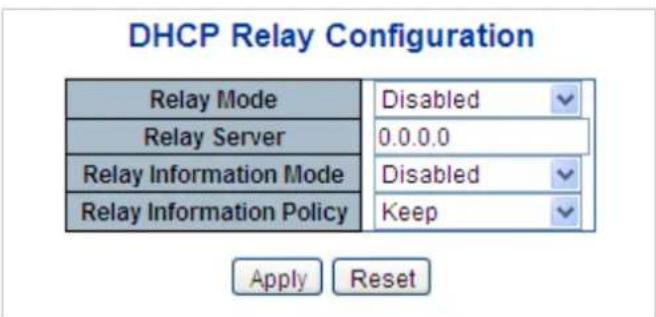
Figure 4-2-13: DHCP Relay Configuration Page Screenshot
The page includes the following fields:
| Object Description | |
| • Relay Mode | Indicates the DHCP relay mode operation. Possible modes are:■ Enabled: Enable DHCP relay mode operation. When enabling DHCP relay mode operation, the agent forwards and transfers DHCP messages between the clients and the server when they are not on the same subnet domain. And the DHCP broadcast message won't flood for security considered.■ Disabled: Disable DHCP relay mode operation. |
| • Relay Server | Indicates the DHCP relay server IP address. A DHCP relay agent is used to forward and transfer DHCP messages between the clients and the server when they are not on the same subnet domain. |
| • Relay Information Mode | Indicates the DHCP relay information mode option operation. Possible modes are:■ Enabled: Enable DHCP relay information mode operation. When enabling DHCP relay information mode operation, the agent inserts specific information (option82) into a DHCP message when forwarding to DHCP server and removing it from a DHCP message when transferring to DHCP client. It only works under DHCP relay operation mode enabled. ■ Disabled: Disable DHCP relay information mode operation. |
| • Relay Information Policy | Indicates the DHCP relay information option policy. When enabling DHCP relay information mode operation, if agent receives a DHCP message that already contains relay agent information. It will enforce the policy. And it only works under DHCP relay information operation mode enabled. Possible policies are: ■ Replace: Replace the original relay information when receiving a DHCP message that already contains it. ■ Keep: Keep the original relay information when receiving a DHCP message that already contains it. ■ Drop: Drop the package when receiving a DHCP message that already contains relay information. |
Buttons
Apply
: Click to apply changes
Reset
: Click to undo any changes made locally and revert to previously saved values.
4.2.1.11 DHCP Relay Statistics
This page provides statistics for DHCP relay. The DHCP Relay Statistics screen in Figure 4-2-14 appears.
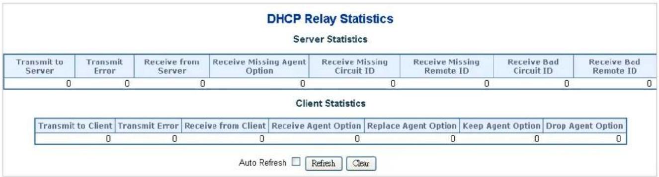
Figure 4-2-14: DHCP Relay Statistics Page Screenshot
The page includes the following fields:
Server Statistics
| Object Description | |
| • Transmit to Server | The packets number that relayed from client to server. |
| • Transmit Error | The packets number that erroneously sent packets to clients. |
| • Receive from Server | The packets number that received packets from server. |
| • Receive Missing Agent Option | The packets number that received packets without agent information options. |
| • Receive Missing Circuit ID | The packets number that received packets whose the Circuit ID option was missing. |
| • Receive Missing Remote ID | The packets number that received packets whose Remote ID option was missing. |
| • Receive Bad Circuit ID | The packets number whose the Circuit ID option did not match known circuit ID. |
| Receive Bad Remote ID | The packets number whose the Remote ID option did not match known Remote ID. |
Client Statistics
| Object Description | |
| • Transmit to Client | The packets number that relayed packets from server to client. |
| • Transmit Error | The packets number that erroneously sent packets to servers. |
| • Receive from Client | The packets number that received packets from server. |
| • Receive Agent Option | The packets number that received packets with relay agent information option. |
| • Replace Agent Option | The packets number that replaced received packets with relay agent information option. |
| • Keep Agent Option | The packets number that kept received packets with relay agent information option. |
| • Drop Agent Option | The packets number that dropped received packets with relay agent information option. |
Buttons
Auto-refresh ☐: Check this box to refresh the page automatically. Automatic refresh occurs every 3 seconds.
Refresh
Click to refresh the page immediately.
Clear
: Clears all statistics.
4.2.1.12 CPU Load
This page displays the CPU load, using an SVG graph. The load is measured as average over the last 100ms, 1 sec and 10 seconds intervals. The last 120 samples are graphed, and the last numbers are displayed as text as well. In order to display the SVG graph, your browser must support the SVG format. Consult the SVG Wiki for more information on browser support.
Specifically, at the time of writing, Microsoft Internet Explorer will need to have a plugin installed to support SVG. The CPU Load screen in Figure 4-2-15 appears.
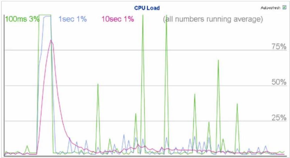
line
| Time | CPU Load (%) | |------|--------------| | 100ms | 3% | | 1sec | 1% | | 10sec | 1% |Figure 4-2-15: CPU Load Page Screenshot
Buttons
Auto-refresh ☐: Check this box to refresh the page automatically. Automatic refresh occurs every 3 seconds.

If your browser cannot display anything on this page, please download Adobe SVG tool and install it in your computer.
4.2.1.13 System Log
The Managed Metro Switch system log information is provided here. The System Log screen in Figure 4-2-16 appears.
System Log Information

The total number of entries is 5 for the given level.
Start from ID 1 with 20 entries per page.
| ID | Level | Time | Message |
| 1 | Informational | 1970-01-01 Thu 00:00:57+00:00 | SYS-BOOTING: Switch just made a cold boot. |
| 2 | Informational | 1970-01-01 Thu 00:01:00+00:00 | DC1 Power OFF |
| 3 | Informational | 1970-01-01 Thu 00:01:06+00:00 | LINK-UPDOWN: Interface GigabitEthernet 1/1, changed state to up. |
| 4 | Informational | 1970-01-01 Thu 00:20:35+00:00 | LINK-UPDOWN: Interface GigabitEthernet 1/1, changed state to down. |
| 5 | Informational | 1970-01-01 Thu 00:38:13+00:00 | LINK-UPDOWN: Interface GigabitEthernet 1/1, changed state to up. |
Figure 4-2-16: System Log Page Screenshot
The page includes the following fields:
| Object Description | |
| • ID | The ID (>= 1) of the system log entry. |
| • Level | The level of the system log entry. The following level types are supported:■Info: Information level of the system log.■Warning: Warning level of the system log.■Error: Error level of the system log.■All: All levels. |
| • Clear Level | To clear the system log entry level. The following level types are supported:■Info: Information level of the system log.■Warning: Warning level of the system log.■Error: Error level of the system log.■All: All levels. |
| • Time | The time of the system log entry. |
| • Message | The message of the system log entry. |
Buttons
Auto-refresh ☐ : Check this box to refresh the page automatically. Automatic refresh occurs every 3 seconds.
Refresh
Updates the system log entries, starting from the current entry ID.
Clear
: Flushes the selected log entries.
Hide
Hides the selected log entries.
Download
Downloads the selected log entries.
k<
Updates the system log entries, starting from the first available entry ID.

Updates the system log entries, ending at the last entry currently displayed.

Updates the system log entries, starting from the last entry currently displayed.

Updates the system log entries, ending at the last available entry ID.
4.2.1.14 Detailed Log
The Managed Metro Switch system detailed log information is provided here. The Detailed Log screen in Figure 4-2-17 appears.
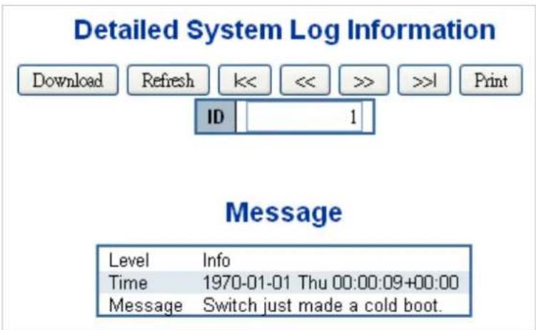
Figure 4-2-17: Detailed Log Page Screenshot
The page includes the following fields:
| Object Description | |
| • ID | The ID (>= 1) of the system log entry. |
| • Message | The message of the system log entry. |
Buttons
Download the system log entry to the current entry ID.
Updates the system log entry to the current entry ID.

Updates the system log entry to the first available entry ID.

Updates the system log entry to the previous available entry ID.

Updates the system log entry to the next available entry ID.

Updates the system log entry to the last available entry ID.

Print the system log entry to the current entry ID.
4.2.1.15 Remote Syslog
Configure remote syslog on this page. The Remote Syslog screen in Figure 4-2-18 appears.
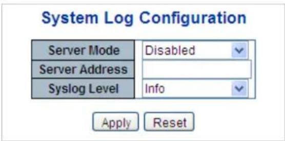
Figure 4-2-18: Remote Syslog Page Screenshot
The page includes the following fields:
| Object Description | |
| • Mode | Indicates the server mode operation. When the mode operation is enabled, the syslog message will send out to syslog server. The syslog protocol is based on UDP communication and received on UDP port 514 and the syslog server will not send acknowledgments back sender since UDP is a connectionless protocol and it does not provide acknowledgments. The syslog packet will always send out even if the syslog server does not exist. Possible modes are:■ Enabled: Enable remote syslog mode operation.■ Disabled: Disable remote syslog mode operation. |
| • Syslog Server IP | Indicates the IPv4 host address of syslog server. If the switch provides DNS feature, it also can be a host name. |
| • Syslog Level | Indicates what kind of message will send to syslog server. Possible modes are:■ Info: Send information, warnings and errors.■ Warning: Send warnings and errors.■ Error: Send errors. |
Buttons

: Click to apply changes

: Click to undo any changes made locally and revert to previously saved values.
4.2.1.16 SMTP Configuration
This page facilitates an SMTP Configuration on the switch. The SMTP Configure screen in Figure 4-2-19 appears.
SMTP Configuration
| SMTP Mode | Enable | |
| SMTP Server | planet.com.tw | (<128 Digits) test |
| SMTP Port | 25 | (1 ~ 65535) |
| SMTP Authentication | Enable | |
| Authentication User Name | 1234 | (< 64 Digits) |
| Authentication Password | ····· | (< 21 Digits) |
| E-mail From | support@planet.com.tw | (< 128 Digits) |
| E-mail Subject | PLANET | (< 64 Digits) |
| E-mail 1 To | support@planet.com.tw | (< 128 Digits) |
| E-mail 2 To | support@planet.com.tw | (< 128 Digits) |
Apply Reset
Figure 4-2-19: SMTP Configuration Page Screenshot
The page includes the following fields:
| Object Description | |
| • SMTP Mode | Controls whether SMTP is enabled on this switch. |
| • SMTP Server | Type the SMTP server name or the IP address of the SMTP server. |
| • SMTP Port | Set port number of SMTP service. |
| • SMTP Authentication | Controls whether SMTP authentication is enabled if authentication is required when an e-mail is sent. |
| • Authentication User Name | Type the user name for the SMTP server if Authentication is Enabled. |
| • Authentication Password | Type the password for the SMTP server if Authentication is Enabled. |
| • E-mail From | Type the sender's e-mail address. This address is used for reply e-mails. |
| • E-mail Subject | Type the subject/title of the e-mail. |
| • E-mail 1 To | Type the receiver's e-mail address. |
| • E-mail 2 To |
Buttons
test Send a test mail to mail server to check whether this account is available or not.
Apply : Click to apply changes
Reset: Click to undo any changes made locally and revert to previously saved values.
4.2.1.17 Fault Alarm
The Managed Metro Switch supports a Fault Alarm feature which can alert the users when there is something wrong with the switches. With this ideal feature, the users would not have to waste time finding where the problem is. It will help to save time and human resource.
This page facilitates an update of the firmware controlling the switch. The Web Firmware Upgrade screen in Figure 4-2-20 appears.
Fault Alarm Control Configuration
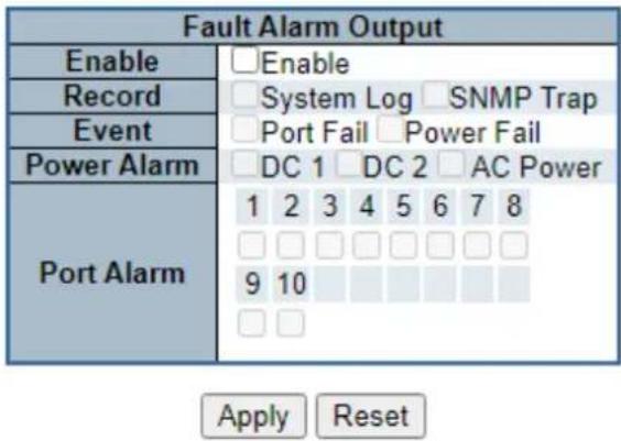
Figure 4-2-20: Fault Alarm Control Configuration page Screenshot
The page includes the following fields:
| Object Description | |
| Enable | Controls whether Fault Alarm is enabled on this switch. |
| Record | Controls whether Record is sending System log or SNMP Trap or both. |
| Action | Controls whether Port Fail or Power Fail or both for fault detecting. |
| Power Alarm | Controls whether AC, DC1 or DC2 or AC power for fault detecting. |
| Port Alarm | Controls which Ports or all for fault detecting. |
Buttons
Apply
: Click to apply changes
Reset
: Click to undo any changes made locally and revert to previously saved values.
4.2.1.18 Digital Input/Output
Digital Input allows user to log external device (such as industrial cooler) dead or alive or something else. System will log a user customized message into system log and syslog, and issue SNMP trap or issue an alarm E-mail.
Digital Input
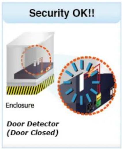
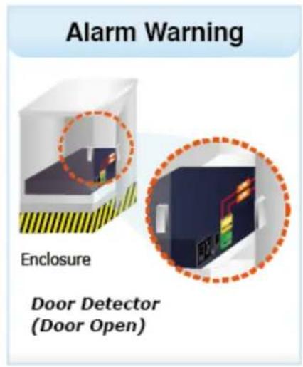
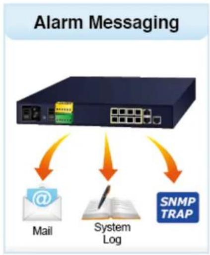
flowchart
graph TD
    A["Alarm Messaging"] --> B["Network Port"]
    B --> C["Mail"]
    B --> D["System Log"]
    B --> E["SNMP TRAP"]
Digital Output allows user to monitor the switch port and power, and let system issue a high or low signal to an external device (such as alarm) when the monitor port or power has failed.
Digital Output
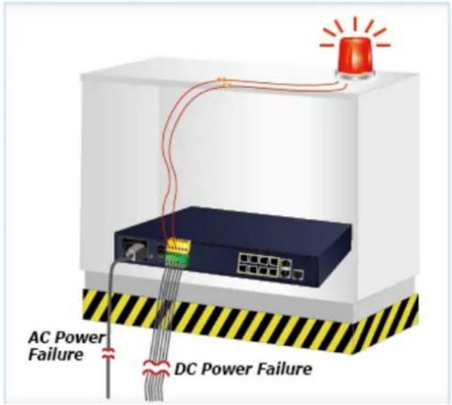
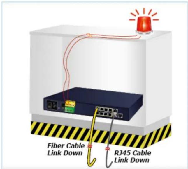
The Configuration screen in Figure 4-2-21 appears.
Digital Input/Output Control Configuration
| Digital Input 0 | Digital Input 1 | ||
| Enable | Enable | Enable | Enable |
| DI Condition | High to Low | DI Condition | High to Low |
| Event Description | Customize DI0 Message. | Event Description | Customize DI1 Message. |
| Action | System Log SNMP Trap | Action | System Log SNMP Trap |
Figure 4-2-21: Digital Input/Output Control Configuration page Screenshot
The page includes the following fields:
| Object Description | |
| Enable | Check the Enable checkbox to enable Digital Input function.Uncheck the Enable checkbox to disable Digital Input function. |
| DI Condition | As Digital Input:Allows user to select High to Low or Low to High. This means a signal received by system is from High to Low or From Low to High. It will trigger an action that logs a customize message or issue the message from the switch. |
| Event Description | Allows user to set a customized message for Digital Input function alarming. |
| Action | As Digital Input:Allows user to record alarm message to System log, syslog or issues out via SNMP Trap or SMTP.As default SNMP Trap and SMTP are disabled, please enable them first if you want to issue alarm message via them. |
| Digital Output 0 | Digital Output 1 | ||
| Enable Enable | Enable Enable | ||
| Action Power Fail Port Fail DI 0 DI 1 | Action Power Fail Port Fail DI 0 DI 1 | ||
| DI Condition High to Low | DI Condition High to Low | ||
| Power Alarm DC 1 DC 2 AC Power | Power Alarm DC 1 DC 2 AC Power | ||
| Port Fail Alarm 1 2 3 4 5 6 7 8 | Port Fail Alarm 1 2 3 4 5 6 7 8 | ||

Figure 4-2-22: Digital Output Control Configuration page Screenshot
The page includes the following fields:
| Object Description | |
| • Enable | Check the Enable checkbox to enable Digital Output function.Uncheck the Enable checkbox to disable Output function. |
| • Action | As Digital Output:Allows user to monitor an alarm from port failure, power failure, Digital Input 0 (DI 0) and Digital Input 1(DI 1) which means if Digital Output has detected these events, then Digital Output would be triggered according to the setting of Condition. |
| • DI Condition | As Digital Output:Allows user to select High to Low or Low to High. This means that when the switch is power-failed or port-failed, then system will issue a High orLow signal to an external device such as an alarm. |
| • Power Alarm | Allows user to choose which power module that needs to be monitored. |
| • Port Fail Alarm | Allows user to choose which port that needs to be monitored. |
Buttons
Apply
: Click to save changes.
Reset
: Click to undo any changes made locally and revert to previously saved values.
4.2.2 Simple Network Management Protocol
4.2.2.1 SNMP Overview
The Simple Network Management Protocol (SNMP) is an application layer protocol that facilitates the exchange of management information between network devices. It is part of the Transmission Control Protocol/Internet Protocol (TCP/IP) protocol suite.
SNMP enables network administrators to manage network performance, find and solve network problems, and plan for network growth.
An SNMP-managed network consists of three key components: Network management stations (NMSs), SNMP agents,
Management information base (MIB) and network-management protocol:
■ Network management stations (NMSs): Sometimes called consoles, these devices execute management applications that monitor and control network elements. Physically, NMSs are usually engineering workstation-caliber computers with fast CPUs, megapixel color displays, substantial memory, and abundant disk space. At least one NMS must be present in each managed environment.
Agents: Agents are software modules that reside in network elements. They collect and store management information such as the number of error packets received by a network element.
■ Management information base (MIB): A MIB is a collection of managed objects residing in a virtual information store. Collections of related managed objects are defined in specific MIB modules.
■ Network-management protocol: A management protocol is used to convey management information between agents and NMSs. SNMP is the Internet community's de facto standard management protocol.
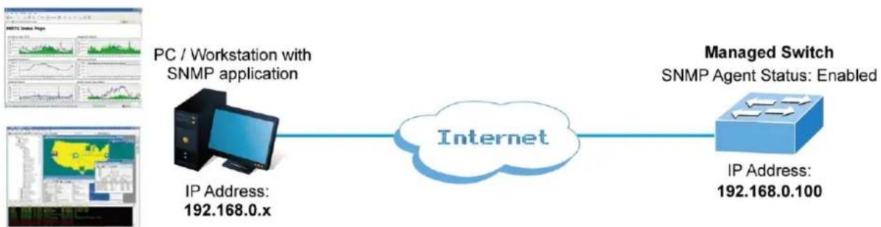
flowchart
graph LR
    A["IP Address: 192.168.0.x"] --> B["Internet"]
    C["PC / Workstation with SNMP application"] --> B
    D["Managed Switch\nSNMP Agent Status: Enabled"] --> B
    B --> E["IP Address: 192.168.0.100"]
Figure 4-2-2-1:
SNMP Operations
SNMP itself is a simple request/response protocol. NMSs can send multiple requests without receiving a response.
- Get -- Allows the NMS to retrieve an object instance from the agent.
Set -- Allows the NMS to set values for object instances within an agent. - Trap -- Used by the agent to asynchronously inform the NMS of some event. The SNMPv2 trap message is designed to replace the SNMPv1 trap message.
SNMP community
An SNMP community is the group that devices and management stations running SNMP belong to. It helps define where information is sent. The community name is used to identify the group. An SNMP device or agent may belong to more than one SNMP community. It will not respond to requests from management stations that do not belong to one of its communities. SNMP
default communities are:
Write = private
Read = public
Use the SNMP Menu to display or configure the Managed Metro Switch's SNMP function. This section has the following items:
■ System Configuration Configure SNMP on this page.
■ System Information The system information is provided here.
■ SNMP Trap Configuration Configure SNMP trap on this page.
■ Trap Source Configuration SNMP trap source configurations.
■ SNMPv3 Communities Configure SNMPv3 communities table on this page.
■ SNMPv3 Users Configure SNMPv3 users table on this page.
■ SNMPv3 Groups Configure SNMPv3 groups table on this page.
■ SNMPv3 Views Configure SNMPv3 views table on this page.
4.2.2.2 SNMP System Configuration
Configure SNMP on this page. The SNMP System Configuration screen in Figure 4-2-2-2 appears.
SNMP System Configuration
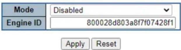
Figure 4-2-2-2: SNMP System Configuration Page Screenshot
The page includes the following fields:
| Object Description | |
| • Mode | Indicates the SNMP mode operation. Possible modes are:■ Enabled: Enable SNMP mode operation.■ Disabled: Disable SNMP mode operation. |
| • Engine ID | Indicates the SNMPv3 engine ID. The string must contain an even number between 10 and 64 hexadecimal digits, but all-zeros and all-'F's are not allowed. Change of the Engine ID will clear all original local users. |
Buttons

: Click to apply changes.
4.2.2.3 SNMP System Information
The switch system information is provided here. The SNMP System Information screen in Figure 4-2-2-3 appears.
System Information Configuration
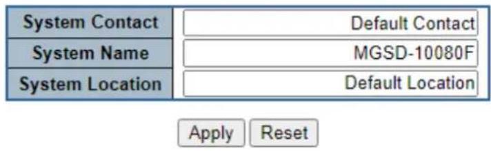
Figure 4-2-2-3: System Information Configuration Page Screenshot
The page includes the following fields:
| Object Description | |
| • System Contact | The textual identification of the contact person for this managed node, together with information on how to contact this person. The allowed string length is 0 to 255, and the allowed content is the ASCII characters from 32 to 126. |
| • System Name | An administratively assigned name for this managed node. By convention, this is the node's fully-qualified domain name. A domain name is a text string drawn from the alphabet (A-Za-z), digits (0-9), minus sign (-). No space characters are permitted as part of a name. The first character must be an alpha character. And the first or last character must not be a minus sign. The allowed string length is 0 to 255. |
| • System Location | The physical location of this node(e.g., telephone closet, 3rd floor). The allowed string length is 0 to 255, and the allowed content is the ASCII characters from 32 to 126. |
Buttons

: Click to save changes.
: Click to undo any changes made locally and revert to previously saved values.
4.2.2.4 SNMP Trap Configuration
Configure SNMP trap on this page. The SNMP Trap Configuration screen in Figure 4-2-2-4 appears.
Trap Destination Configurations
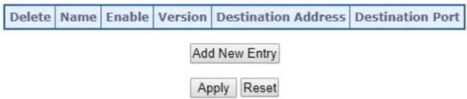
Click 'Add New Entry' and then the SNMP Trap Configuration page appears.
SNMP Trap Configuration
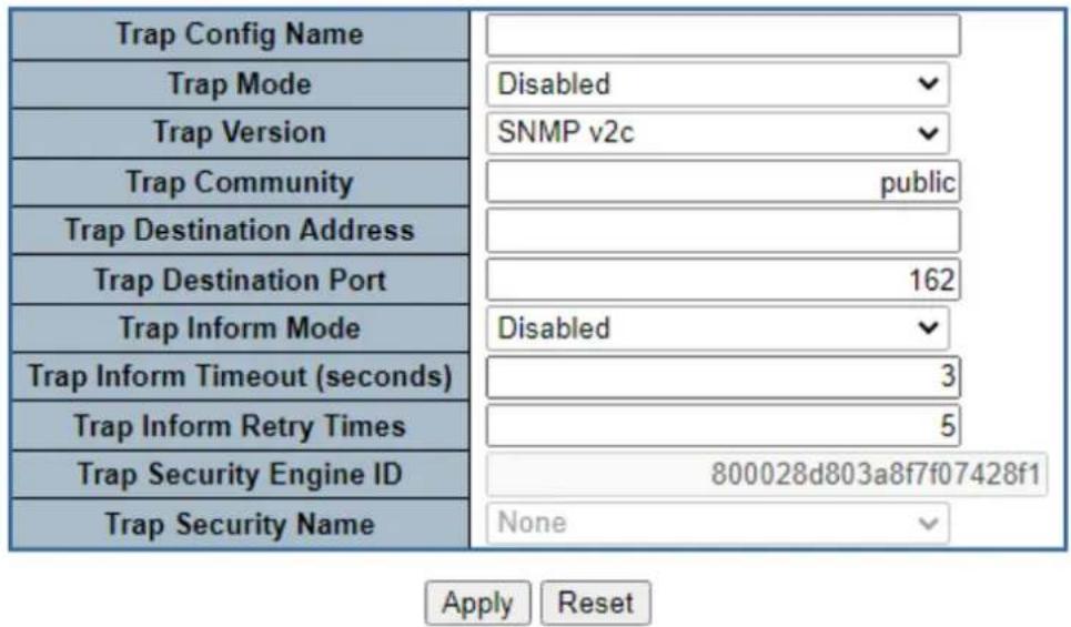
Figure 4-2-2-4: SNMP Trap Configuration Page Screenshot
The page includes the following fields:
| Object Description | |
| Trap Config | Indicates which trap Configuration's name for configuring. The allowed string length is 0 to 255, and the allowed content is ASCII characters from 33 to 126. |
| Trap Mode | Indicates the SNMP trap mode operation. Possible modes are:■ Enabled: Enable SNMP trap mode operation.■ Disabled: Disable SNMP trap mode operation. |
| Trap Version | Indicates the SNMP trap supported version. Possible versions are:■ SNMP v1: Set SNMP trap supported version 1.■ SNMP v2c: Set SNMP trap supported version 2c.■ SNMP v3: Set SNMP trap supported version 3. |
| Trap Community | Indicates the community access string when send SNMP trap packet. The allowed string length is 0 to 255, and the allowed content is the ASCII characters from 33 to 126. |
| Trap Destination Address | Indicates the SNMP trap destination address. |
| Trap Destination Port | Indicates the SNMP trap destination port. SNMP Agent will send SNMP message via this port, the port range is 1~65535. |
| Trap Inform Mode | Indicates the SNMP trap inform mode operation. Possible modes are:■ Enabled: Enable SNMP trap authentication failure.■ Disabled: Disable SNMP trap authentication failure. |
| Trap Inform Timeout (seconds) | Indicates the SNMP trap inform timeout.The allowed range is 0 to 2147. |
| Trap Inform Retry Times | Indicates the SNMP trap inform retry times.The allowed range is 0 to 255. |
| Trap Probe Security Engine ID | Indicates the SNMPv3 trap probe security engine ID mode of operation. Possible values are:■ Enabled: Enable SNMP trap probe security engine ID mode of operation.■ Disabled: Disable SNMP trap probe security engine ID mode of operation. |
| Trap Security Engine ID | Indicates the SNMP trap security engine ID. SNMPv3 sends traps and informs using USM for authentication and privacy. A unique engine ID for these traps and informs is needed. When "Trap Probe Security Engine ID" is enabled, the ID will be probed automatically. Otherwise, the ID specified in this field is used. The string must contain an even number(in hexadecimal format) with number of digits between 10 and 64, but all-zeros and all-'F's are not allowed. |
| Trap Security Name | Indicates the SNMP trap security name. SNMPv3 traps and informs using USM for authentication and privacy. A unique security name is needed when traps and informs are enabled. |
| System | Enable/disable that the Interface group's traps. Possible traps are:■ Warm Start: Enable/disable Warm Start trap.■ Cold Start: Enable/disable Cold Start trap. |
| Interface | Indicates that the Interface group's traps. Possible traps are:■ Link Up: Enable/disable Link up trap.■ Link Down: Enable/disable Link down trap.■ LLDP: Enable/disable LLDP trap. |
| AAA | Indicates that the AAA group's traps. Possible traps are:Authentication Fail : Enable/disable SNMP trap authentication failure trap. |
| Switch | Indicates that the Switch group's traps. Possible traps are:■ STP: Enable/disable STP trap.■ RMON: Enable/disable RMON trap. |
4.2.2.5 SNMP Trap Source Configuration
This page provides SNMP trap source configurations. A trap is sent for the given trap source if at least one filter with filter type included matches the filter, and no filters with filter type excluded matches.
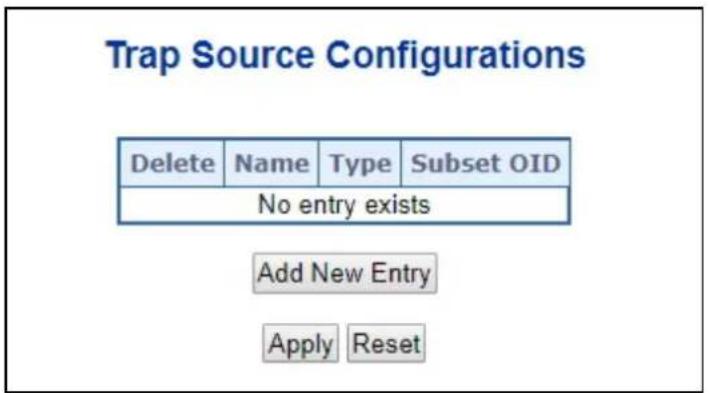
Figure 4-2-2-5: SNMP Trap Source Configuration Page Screenshot
Click "Add New Entry" to add a new entry. The maximum entry count is 32.
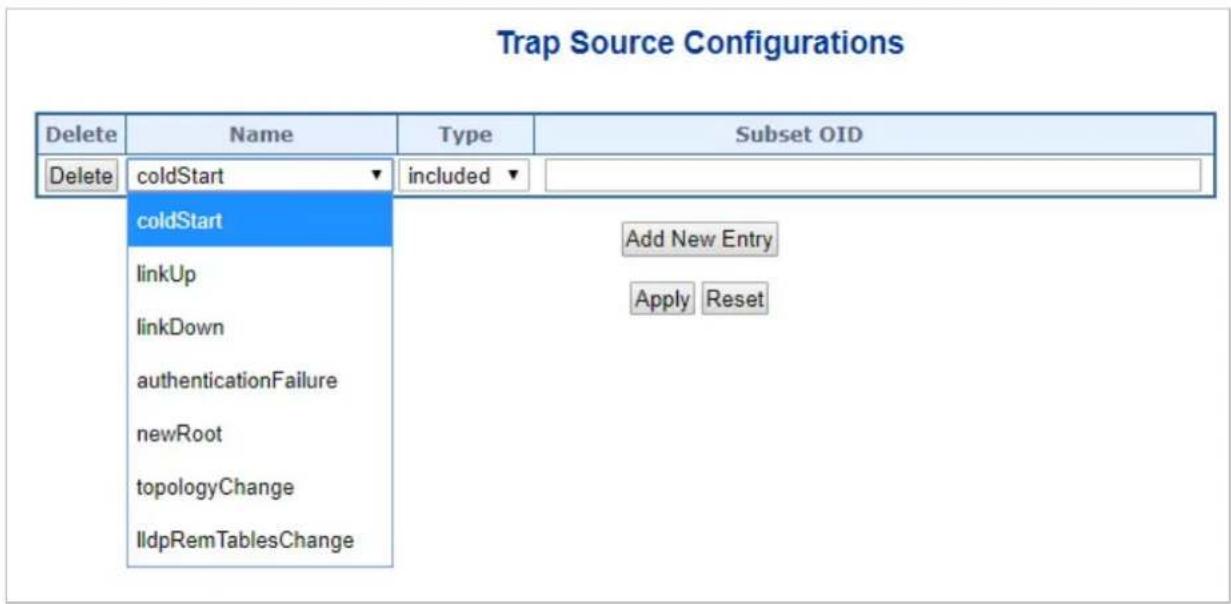
Figure 4-2-2-6: SNMP Trap Source Configuration Page Screenshot
The page includes the following fields:
| Object Description | |
| • Name | Indicates the name for the entry. |
| • Type | The filter type for the entry. Possible types are:■ included: An optional flag to indicate a trap is sent for the given trap source is matched.■ excluded: An optional flag to indicate a trap is not sent for the given trap source is matched. |
| • Subset OID | The subset OID for the entry.The value should depend on the what kind of trap name.For example, the ifldex is the subset OID of linkUp and linkDown. A valid subset OID is one or more digital number(0-4294967295) or asterisk(*) which are separated by dots(.). The first character must not begin with asterisk(*) and the maximum of OID count must not exceed 128. |
Buttons
Add New Entry: Click to add a new community entry. The maximum entry count is 32
Apply : Click to apply changes
Reset : Click to undo any changes made locally and revert to previously saved values.
4.2.2.6 SNMPv3 Communities
Configure SNMPv3 communities table on this page. The entry index key is Community. The SNMPv3 Communities screen in Figure 4-2-2-7 appears.
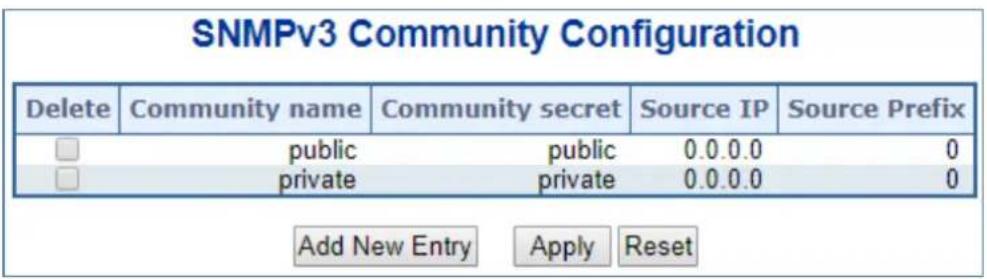
Figure 4-2-2-7: SNMPv3 Communities Configuration Page Screenshot
The page includes the following fields:
| Object Description | |
| Delete | Check to delete the entry. It will be deleted during the next save. |
| Community | Indicates the community access string to permit access to SNMPv3 agent. The allowed string length is 1 to 32, and the allowed content is ASCII characters from 33 to 126. The community string will be treated as security name and map a SNMPv1 or SNMPv2c community string. |
| Source IP | Indicates the SNMP access source address. A particular range of source addresses can be used to restrict source subnet when combined with source mask. |
| Source Mask | Indicates the SNMP access source address mask. |
Buttons
Add New Entry
Click to add a new community entry.
Apply
: Click to apply changes
Reset
: Click to undo any changes made locally and revert to previously saved values.
4.2.2.7 SNMPv3 Users
Configure SNMPv3 users table on this page. The entry index keys are Engine ID and User Name. The SNMPv3 Users screen in
Figure 4-2-2-8 appears.
SNMPv3 User Configuration

Figure 4-2-2-8: SNMPv3 Users Configuration Page Screenshot
The page includes the following fields:
| Object Description | |
| Delete | Check to delete the entry. It will be deleted during the next save. |
| Engine ID | An octet string identifying the engine ID that this entry should belong to. The string must contain an even number(in hexadecimal format) with number of digits between 10 and 64, but all-zeros and all-'F's are not allowed. The SNMPv3 architecture uses the User-based Security Model (USM) for message security and the View-based Access Control Model (VACM) for access control. For the USM entry, the usmUserEngineID and usmUserName are the entry's keys.In a simple agent, usmUserEngineID is always that agent's own snmpEngineID value. The value can also take the value of the snmpEngineID of a remote SNMP engine with which this user can communicate. In other words, if user engine ID equal system engine ID then it is local user; otherwise it's remote user. |
| User Name | A string identifying the user name that this entry should belong to. The allowed string length is 1 to 32, and the allowed content is ASCII characters from 33 to 126. |
| Security Level | Indicates the security model that this entry should belong to. Possible security models are:■NoAuth, NoPriv: None authentication and none privacy.■Auth, NoPriv: Authentication and none privacy.■Auth, Priv: Authentication and privacy.The value of security level cannot be modified if entry already exist. That means must first ensure that the value is set correctly. |
| Authentication Protocol | Indicates the authentication protocol that this entry should belong to. Possible authentication protocol are:■None: None authentication protocol.■MD5: An optional flag to indicate that this user using MD5 authentication protocol.■ SHA: An optional flag to indicate that this user using SHA authentication protocol.The value of security level cannot be modified if entry already exist. That means must first ensure that the value is set correctly. |
| • Authentication Password | A string identifying the authentication pass phrase. For MD5 authentication protocol, the allowed string length is 8 to 32. For SHA authentication protocol, the allowed string length is 8 to 40. The allowed content is the ASCII characters from 33 to 126. |
| • Privacy Protocol | Indicates the privacy protocol that this entry should belong to. Possible privacy protocol are:■ None: None privacy protocol.■ DES: An optional flag to indicate that this user using DES authentication protocol.■ AES: An optional flag to indicate that this user uses AES authentication protocol. |
| • Privacy Password | A string identifying the privacy pass phrase. The allowed string length is 8 to 32, and the allowed content is the ASCII characters from 33 to 126. |
Buttons
Add New Entry
Click to add a new user entry.
Apply
: Click to apply changes
Reset
Click to undo any changes made locally and revert to previously saved values.
4.2.2.8 SNMPv3 Groups
Configure SNMPv3 groups table on this page. The entry index keys are Security Model and Security Name. The SNMPv3 Groups screen in Figure 4-2-2-9 appears.
SNMPv3 Group Configuration
| Delete | Security Model | Security Name | Group Name |
| v1 | public | default_ro_group | |
| v1 | private | default_rw_group | |
| v2c | public | default_ro_group | |
| v2c | private | default_rw_group |
Add New Entry
Apply
Reset
Figure 4-2-2-9: SNMPv3 Groups Configuration Page Screenshot
The page includes the following fields:
| Object Description | |
| Delete | Check to delete the entry. It will be deleted during the next save. |
| Security Model | Indicates the security model that this entry should belong to. Possible security models are:■ v1: Reserved for SNMPv1.■ v2c: Reserved for SNMPv2c.■ usm: User-based Security Model (USM). |
| Security Name | A string identifying the security name that this entry should belong to.The allowed string length is 1 to 32, and the allowed content is the ASCII characters from 33 to 126. |
| Group Name | A string identifying the group name that this entry should belong to.The allowed string length is 1 to 32, and the allowed content is the ASCII characters from 33 to 126. |
Buttons
Add New Entry
Click to add a new group entry.
Apply
: Click to apply changes
Reset
Click to undo any changes made locally and revert to previously saved values.
4.2.2.9 SNMPv3 Views
Configure SNMPv3 views table on this page. The entry index keys are View Name and OID Subtree. The SNMPv3 Views screen in Figure 4-2-2-10 appears.
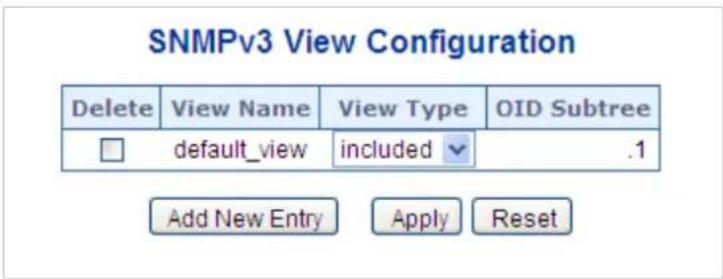
Figure 4-2-2-10: SNMPv3 Views Configuration Page Screenshot
The page includes the following fields:
| Object Description | |
| Delete | Check to delete the entry. It will be deleted during the next save. |
| View Name | A string identifying the view name that this entry should belong to. The allowed string length is 1 to 32, and the allowed content is the ASCII characters from 33 to 126. |
| View Type | Indicates the view type that this entry should belong to. Possible view type are:■included:An optional flag to indicate that this view subtree should be included.■excluded:An optional flag to indicate that this view subtree should be excluded.In general, if a view entry's view type is 'excluded', it should be exist another view entry which view type is 'included' and it's OID subtree overstep the 'excluded' view entry. |
| OID Subtree | The OID defining the root of the subtree to add to the named view. The allowed OID length is 1 to 128. The allowed string content is digital number or asterisk(*). |
Buttons
Add New Entry
Click to add a new view entry.
Apply
: Click to apply changes
Reset
: Click to undo any changes made locally and revert to previously saved values.
4.2.2.10 SNMPv3 Access
Configure SNMPv3 accesses table on this page. The entry index keys are Group Name, Security Model and Security Level.
The SNMPv3 Access screen in Figure 4-2-2-11 appears.
SNMPv3 Access Configuration

Figure 4-2-2-11: SNMPv3 Accesses Configuration Page Screenshot
The page includes the following fields:
| Object Description | |
| Delete | Check to delete the entry. It will be deleted during the next save. |
| Group Name | A string identifying the group name that this entry should belong to. The allowed string length is 1 to 32, and the allowed content is the ASCII characters from 33 to 126. |
| Security Model | Indicates the security model that this entry should belong to. Possible security models are:any: Accepted any security model (v1|v2c|usm).v1: Reserved for SNMPv1.v2c: Reserved for SNMPv2c.usm: User-based Security Model (USM) |
| Security Level | Indicates the security model that this entry should belong to. Possible security models are:NoAuth, NoPriv: None authentication and none privacy.Auth, NoPriv: Authentication and none privacy.Auth, Priv: Authentication and privacy. |
| Read View Name | The name of the MIB view defining the MIB objects for which this request may request the current values. The allowed string length is 1 to 32, and the allowed content is the ASCII characters from 33 to 126. |
| Write View Name | The name of the MIB view defining the MIB objects for which this request may potentially SET new values. The allowed string length is 1 to 32, and the allowed content is the ASCII characters from 33 to 126. |
Buttons
Add New Entry
Click to add a new access entry.
Apply
: Click to apply changes
Reset
: Click to undo any changes made locally and revert to previously saved values.
4.2.3 RMON
RMON is the most important expansion of the standard SNMP. RMON is a set of MIB definitions, used to define standard network monitor functions and interfaces, enabling the communication between SNMP management terminals and remote monitors. RMON provides a highly efficient method to monitor actions inside the subnets.
MID of RMON consists of 10 groups. The switch supports the most frequently used groups 1, 2, 3 and 9:
Statistics: Maintain basic usage and error statistics for each subnet monitored by the agent.
History: Record periodical statistic samples available from statistics.
Alarm: Allow management console users to set any count or integer for sample intervals and alert thresholds for RMON agent records.
Event: A list of all events generated by RMON agent.
Alarm depends on the implementation of Event. Statistics and History display some current or history subnet statistics. Alarm and Event provide a method to monitor any integer data change in the network, and provide some alerts upon abnormal events (sending Trap or record in logs).
4.2.3.1 RMON Alarm Configuration
Configure RMON Alarm table on this page. The entry index key is ID.; screen in Figure 4-2-3-1 appears.
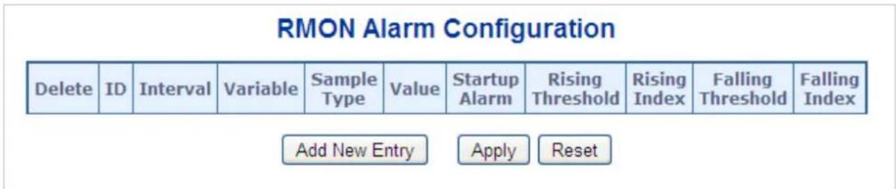
Figure 4-2-3-1: RMON Alarm Configuration Page Screenshot
The page includes the following fields:
| Object Description | |
| Delete | Check to delete the entry. It will be deleted during the next save. |
| ID | Indicates the index of the entry. The range is from 1 to 65535. |
| Interval | Indicates the interval in seconds for sampling and comparing the rising and falling threshold. The range is from 1 to 2^31-1 . |
| Variable | Indicates the particular variable to be sampled; the possible variables are:InOctets: The total number of octets received on the interface, including framing characters.InUcastPkts: The number of uni-cast packets delivered to a higher-layer protocol.InNUcastPkts: The number of broadcast and multi-cast packets delivered toa higher-layer protocol.■InDiscards: The number of inbound packets that are discarded even the packets are normal.■InErrors: The number of inbound packets that contains errors preventing them from being deliverable to a higher-layer protocol.■InUnknownProtos: the number of the inbound packets that is discarded because of the unknown or un-support protocol.■OutOctets: The number of octets transmitted out of the interface, including framing characters.■OutUcastPkts: The number of uni-cast packets that requests to transmit.■OutNUcastPkts: The number of broadcast and multi-cast packets that requests to transmit.■OutDiscards: The number of outbound packets that is discarded even the packets are normal.■OutErrors: The number of outbound packets that could not be transmitted because of errors.■OutQLen: The length of the output packet queue (in packets). |
| • Sample Type | The method of sampling the selected variable and calculating the value to be compared against the thresholds; possible sample types are:■Absolute: Get the sample directly.■Delta: Calculate the difference between samples (default). |
| • Value | The value of the statistic during the last sampling period. |
| • Startup Alarm | The method of sampling the selected variable and calculating the value to be compared against the thresholds; possible sample types are:■RisingTrigger alarm when the first value is larger than the rising threshold.■FallingTrigger alarm when the first value is less than the falling threshold.■RisingOrFallingTrigger alarm when the first value is larger than the rising threshold or less than the falling threshold (default). |
| • Rising Threshold | Rising threshold value (-2147483648-2147483647). |
| • Rising Index | Rising event index (1-65535). |
| • Falling Threshold | Falling threshold value (-2147483648-2147483647) |
| • Falling Index | Falling event index (1-65535). |
Buttons
Add New Entry
Click to add a new community entry.
Apply
: Click to apply changes
Reset
: Click to undo any changes made locally and revert to previously saved values.
4.2.3.2 RMON Alarm Status
This page provides an overview of RMON Alarm entries. Each page shows up to 99 entries from the Alarm table, default being 20, selected through the "entries per page" input field. When first visited, the web page will show the first 20 entries from the beginning of the Alarm table. The first displayed will be the one with the lowest ID found in the Alarm table; screen in Figure 4-2-3-2 appears.
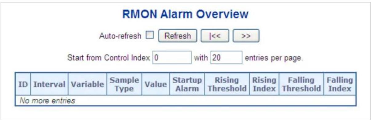
Figure 4-2-3-2: RMON Alarm Overview Page Screenshot
The page includes the following fields:
| Object Description | |
| • ID | Indicates the index of Alarm control entry. |
| • Interval | Indicates the interval in seconds for sampling and comparing the rising and falling threshold. |
| • Variable | Indicates the particular variable to be sampled. |
| • Sample Type | The method of sampling the selected variable and calculating the value to be compared against the thresholds. |
| • Value | The value of the statistic during the last sampling period. |
| • Startup Alarm | The alarm that may be sent when this entry is first set to valid. |
| • Rising Threshold | Rising threshold value |
| • Rising Index | Rising event index |
| • Falling Threshold | Falling threshold value |
| • Falling Index | Falling event index |
Buttons

Click to refresh the page immediately.
Auto-refresh ☐: Check this box to refresh the page automatically. Automatic refresh occurs every 3 seconds.

Updates the table, starting from the first entry in the Alarm Table, i.e. the entry with the lowest ID.

Updates the table, starting with the entry after the last entry currently displayed.
4.2.3.3 RMON Event Configuration
Configure RMON Event table on this page. The entry index key is ID; screen in Figure 4-2-3-3 appears.
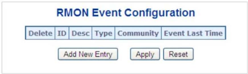
Figure 4-2-3-3: RMON Event Configuration Page Screenshot
The page includes the following fields:
| Object Description | |
| Delete | Check to delete the entry. It will be deleted during the next save. |
| ID | Indicates the index of the entry. The range is from 1 to 65535. |
| Desc | Indicates this event, the string length is from 0 to 127, default is a null string. |
| Type | Indicates the notification of the event; the possible types are:■none: The total number of octets received on the interface, including framing characters.■log: The number of uni-cast packets delivered to a higher-layer protocol.■snmptrap: The number of broad-cast and multi-cast packets delivered to a higher-layer protocol.■logandtrap: The number of inbound packets that are discarded even the packets are normal. |
| Community | Specify the community when trap is sent, the string length is from 0 to 127, default is "public". |
| Event Last Time | Indicates the value of sysUpTime at the time this event entry last generated an event. |
Buttons
Add New Entry
Click to add a new community entry.
Apply
: Click to apply changes
Reset
: Click to undo any changes made locally and revert to previously saved values.
4.2.3.4 RMON Event Status
This page provides an overview of RMON Event table entries. Each page shows up to 99 entries from the Event table, default being 20, selected through the "entries per page" input field. When first visited, the web page will show the first 20 entries from the beginning of the Event table. The first displayed will be the one with the lowest Event Index and Log Index found in the Event table; screen in Figure 4-2-3-4 appears.
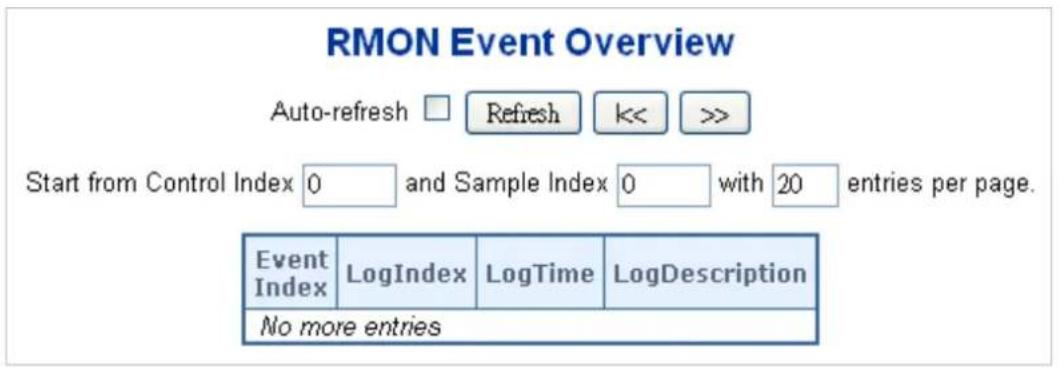
Figure 4-2-3-4: RMON Event Overview Page Screenshot
The page includes the following fields:
| Object Description | |
| • Event Index | Indicates the index of the event entry. |
| • Log Index | Indicates the index of the log entry. |
| • Logtime | Indicates Event log time. |
| • Log Description | Indicates the Event description. |
Buttons
Refresh: Click to refresh the page immediately.
Auto-refresh ☐: Check this box to refresh the page automatically. Automatic refresh occurs every 3 seconds.
Updates the table starting from the first entry in the Alarm Table, i.e. the entry with the lowest ID.
: Updates the table, starting with the entry after the last entry currently displayed.
: Updates the table, starting with the entry after the last entry currently displayed.
4.2.3.5 RMON History Configuration
Configure RMON History table on this page. The entry index key is ID; screen in Figure 4-2-3-5 appears.
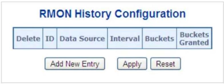
flowchart
graph TD
    A["Delete"] --> B["ID"]
    B --> C["Data Source"]
    C --> D["Interval"]
    D --> E["Buckets"]
    E --> F["Buckets Granted"]
    G["Add New Entry"] --> H["Apply"]
    H --> I["Reset"]
Figure 4-2-3-5: RMON History Configuration Page Screenshot
The page includes the following fields:
| Object Description | |
| Delete | Check to delete the entry. It will be deleted during the next save. |
| ID | Indicates the index of the entry. The range is from 1 to 65535. |
| Data Source | Indicates the port ID which wants to be monitored. |
| Interval | Indicates the interval in seconds for sampling the history statistics data. The range is from 1 to 3600, default value is 1800 seconds. |
| Buckets | Indicates the maximum data entries associated this History control entry stored in RMON. The range is from 1 to 3600, default value is 50. |
| Buckets Granted | The number of data will be saved in the RMON. |
Buttons
Add New Entry
Click to add a new community entry.
Apply
: Click to apply changes
Reset
: Click to undo any changes made locally and revert to previously saved values.
4.2.3.6 RMON History Status
This page provides an detail of RMON history entries; screen in Figure 4-2-3-6 appears.
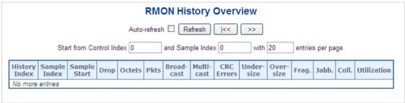
Figure 4-2-3-6: RMON History Overview Page Screenshot
The page includes the following fields:
| Object | Description |
| History Index | Indicates the index of History control entry. |
| Sample Index | Indicates the index of the data entry associated with the control entry. |
| Sample Start | The value of sysUpTime at the start of the interval over which this sample was measured. |
| Drop | The total number of events in which packets were dropped by the probe due to lack of resources. |
| Octets | The total number of octets of data (including those in bad packets) received on the network. |
| Pkts | The total number of packets (including bad packets, broadcast packets, and multicast packets) received. |
| Broadcast | The total number of good packets received that were directed to the broadcast address. |
| Multicast | The total number of good packets received that were directed to a multicast address. |
| CRC Errors | The total number of packets received that had a length (excluding framing bits, but including FCS octets) of between 64 and 1518 octets, inclusive, but had either a bad Frame Check Sequence (FCS) with an integral number of octets (FCS Error) or a bad FCS with a non-integral number of octets (Alignment Error). |
| Undersize | The total number of packets received that were less than 64 octets. |
| Oversize | The total number of packets received that were longer than 1518 octets. |
| Frag. | The number of frames whose size is less than 64 octets received with invalid CRC. |
| Jabb. | The number of frames whose size is larger than 64 octets received with invalid CRC. |
| Coll. | The best estimate of the total number of collisions in this Ethernet segment. |
| Utilization | The best estimate of the mean physical layer network utilization on this interfaceduring this sampling interval, in hundredths of a percent. |
Buttons

Click to refresh the page immediately.
Auto-refresh ☐: Check this box to refresh the page automatically. Automatic refresh occurs every 3 seconds.

Updates the table, starting from the first entry in the History table, i.e., the entry with the lowest History Index and Sample Index

: Updates the table, starting with the entry after the last entry currently displayed.
4.2.3.7 RMON Statistics Configuration
Configure RMON Statistics table on this page. The entry index key is ID; screen in Figure 4-2-3-7 appears.
RMON Statistics Configuration

Add New Entry
Save Reset
Figure 4-2-3-7: RMON Statistics Configuration Page Screenshot
The page includes the following fields:
| Object Description | |
| Delete | Check to delete the entry. It will be deleted during the next save. |
| ID | Indicates the index of the entry. The range is from 1 to 65535. |
| Data Source | Indicates the port ID which wants to be monitored. |
Buttons
Click to add a new community entry.

: Click to apply changes
Click to undo any changes made locally and revert to previously saved values.
4.2.3.8 RMON Statistics Status
This page provides an overview of RMON Statistics entries. Each page shows up to 99 entries from the Statistics table, default being 20, selected through the "entries per page" input field. When first visited, the web page will show the first 20 entries from the beginning of the Statistics table. The first displayed will be the one with the lowest ID found in the Statistics table; screen in
Figure 4-2-3-8 appears.
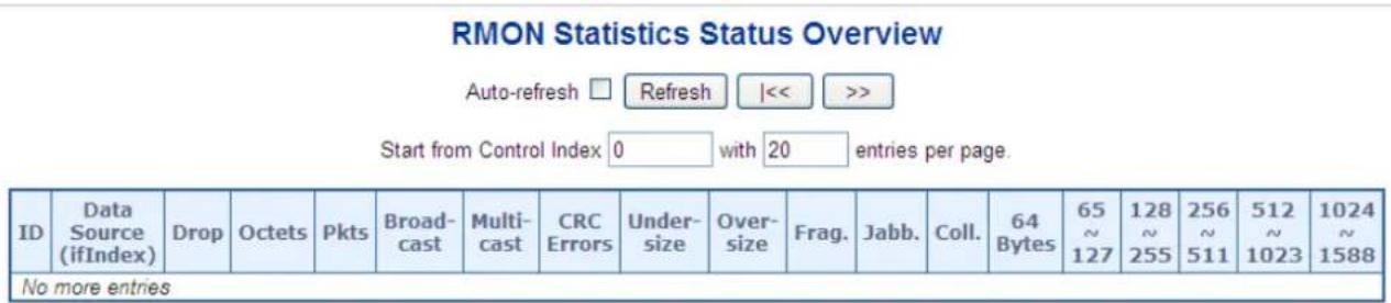
Figure 4-2-3-8: RMON Statistics Status Overview Page Screenshot
The page includes the following fields:
| Object Description | |
| • ID | Indicates the index of Statistics entry. |
| • Data Source (ifIndex) | The port ID which wants to be monitored. |
| • Drop | The total number of events in which packets were dropped by the probe due to lack of resources. |
| • Octets | The total number of octets of data (including those in bad packets) received on the network. |
| • Pkts | The total number of packets (including bad packets, broadcast packets, and multicast packets) received. |
| • Broadcast | The total number of good packets received that were directed to the broadcast address. |
| • Multicast | The total number of good packets received that were directed to a multicast address. |
| • CRC Errors | The total number of packets received that had a length (excluding framing bits, but including FCS octets) of between 64 and 1518 octets. |
| • Undersize | The total number of packets received that were less than 64 octets. |
| • Oversize | The total number of packets received that were longer than 1518 octets. |
| • Frag. | The number of frames whose size is less than 64 octets received with invalid CRC. |
| • Jabb. | The number of frames whose size is larger than 64 octets received with invalid CRC. |
| • Coll. | The best estimate of the total number of collisions in this Ethernet segment. |
| 64 Bytes | The total number of packets (including bad packets) received that were 64 octets in length. |
| 65~127 | The total number of packets (including bad packets) received that were between 65 to 127 octets in length. |
| 128~255 | The total number of packets (including bad packets) received that were between 128 to 255 octets in length. |
| 256~511 | The total number of packets (including bad packets) received that were between 256 to 511 octets in length. |
| 512~1023 | The total number of packets (including bad packets) received that were between 512 to 1023 octets in length. |
| 1024~1518 | The total number of packets (including bad packets) received that were between 1024 to 1518 octets in length. |
Buttons
Refresh
Click to refresh the page immediately.
Auto-refresh ☐: Check this box to refresh the page automatically. Automatic refresh occurs every 3 seconds.

Updates the table, starting from the first entry in the Alarm Table, i.e. the entry with the lowest ID.

Updates the table, starting with the entry after the last entry currently displayed.
4.2.4 DHCP server
4.2.4.1 DHCP Server Mode Configuration
Configure DHCP server mode on this page. The entry index key is ID.; screen in Figure 4-2-4-1 appears.
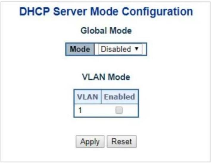
Figure 4-2-4-1: DHCP Server Mode Page Screenshot
The page includes the following fields:
Global Mode
Configure operation mode to enable/disable DHCP server per system.
| Object Description | |
| • Mode | Configure the operation mode per system. Possible modes are:Enabled: Enable DHCP server per system.Disabled: Disable DHCP server pre system. |
VLAN Mode
Configure operation mode to enable/disable DHCP server per VLAN.
| Object Description | |
| • VLAN Range | Indicate the VLAN range in which DHCP server is enabled or disabled.The first VLAN ID must be smaller than or equal to the second VLAN ID. BUT, if the VLAN range contains only 1 VLAN ID, then you can just input it into either one of the first and second VLAN ID or both.On the other hand, if you want to disable existed VLAN range, then you can follow the steps.1. press “Add VLANRange” to add a new VLAN range.2. input the VLAN range that you want to disable.3. choose Mode to be Disabled.4. press “Apply” to apply the change.Then, you will see the disabled VLAN range is removed from the DHCP Server mode configuration page. |
| • Mode | ■ Indicate the operation mode per VLAN. Possible modes are:Enabled: Enable DHCP server per VLAN Cooperative: Disable DHCP server pre VLAN. |
Buttons

: Click to apply changes

: Click to undo any changes made locally and revert to previously saved values.
4.2.4.2 DHCP Server excluded IP Configuration
Configure excluded IP addresses. DHCP server will not allocate these excluded IP addresses to DHCP client.; screen in Figure 4-2-4-2 appears.
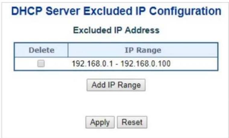
Figure 4-2-4-2: DHCP server excluded Page Screenshot
The page includes the following fields:
| Object Description | |
| • IP range | Define the IP range to be excluded IP addresses. The first excluded IP must be smaller than or equal to the second excluded IP. BUT, if the IP range contains only 1 excluded IP, then you can just input it to either one of the first and second excluded IP or both. |
Buttons
Add IP Range : Click to add a new excluded IP range.
Apply : Click to apply changes.
Reset: Click to undo any changes made locally and revert to previously saved values.
4.2.4.3 DHCP Server pool Configuration
This page manages DHCP pools. According to the DHCP pool, DHCP server will allocate IP address and deliver configuration parameters to DHCP client. screen in Figure 4-2-4-3 appears.
DHCP Server Pool Configuration
Pool Setting
| Delete | Name | Type | IP | Subnet Mask | Lease Time |
| vlan1 | Network | 192.168.0.100 | 255.255.255.0 | 3 days 0 hours 0 minutes |
Figure 4-2-4-3: DHCP server pool Page Screenshot
The page includes the following fields:
| Object Description | |
| • Name | Configure the pool name that accepts all printable characters, except white space. If you want to configure the detail settings, you can click the pool name to go into the configuration page. |
| • Type | Display which type of the pool is.Network: the pool defines a pool of IP addresses to service more than one DHCP client.Host: the pool services for a specific DHCP client identified by client identifier or hardware address. |
| • IP | Display network number of the DHCP address pool.If "-" is displayed, it means not defined |
| • Subnet Mask | Display subnet mask of the DHCP address pool.If "-" is displayed, it means not defined. |
| • Lease Time | Display lease time of the pool. |
Buttons
Add New Pool
Click to add a new excluded IP range.
Apply
: Click to apply changes
Reset
: Click to undo any changes made locally and revert to previously saved values.
4.2.4.4 DHCP Server Statistics
This page displays the database counters and the number of DHCP messages sent and received by DHCP server.. screen in Figure 4-2-4-4 appears.
Auto-refresh

Refresh
Clear
DHCP Server Statistics
Database Counters
| Pool | Excluded IP Address | Declined IP Address |
| 1 | 1 | 0 |
Binding Counters
| Automatic Binding | Manual Binding | Expired Binding |
| 0 | 0 | 0 |
DHCP Message Received Counters
| DISCOVER | REQUEST | DECLINE | RELEASE | INFORM |
| 0 | 0 | 0 | 0 | 0 |
DHCP Message Sent Counters
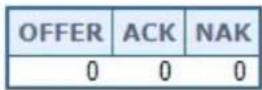
Figure 4-2-4-4: DHCP server Statistics Page Screenshot
The page includes the following fields:
Database Counters
| Object Description | |
| • Pool | Number of pools |
| • Excluded IP Address | Number of excluded IP address ranges |
| • Declined IP Address | Number of declined IP addresses. |
Binding Counters
| Object Description | |
| • Automatic Binding | Number of bindings with network-type pools |
| • Manual Binding | Number of bindings that administrator assigns an IP address to a client. That is, the pool is of host type. |
| • Expired Binding | Number of bindings that their lease time expired or they are cleared from Automatic/Manual type bindings. |
DHCP message Received Counters
| Object Description | |
| • Discover | Number of DHCP DISCOVER messages received. |
| • Request | Number of DHCP REQUEST messages received. |
| • Decline | Number of DHCP DECLINE messages received. |
| • Release | Number of DHCP RELEASE messages received. |
| • Inform | Number of DHCP INFORM messages received. |
DHCP message Sent Counters
| Object Description | |
| • Offer | Number of DHCP OFFER messages sent. |
| • ACK | Number of DHCP ACK messages sent. |
| • NAK | Number of DHCP NAK messages sent. |
Buttons
Auto-refresh
seconds.
: Check this box to refresh the page automatically.
Apply
: Click to apply changes
Reset
: Click to undo any changes made locally and revert to previously saved values
4.2.4.5 DHCP Server Binding IP Configuration
This page displays bindings generated for DHCP clients. screen in Figure 4-2-4-5 appears.
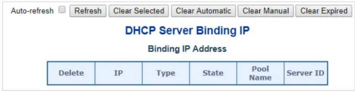
Figure 4-2-4-5: DHCP server Binding IP page Screenshot
The page includes the following fields:
| Object Description | |
| • IP | Display IP address allocated to DHCP client. |
| • Type | Display type of binding. Possible types are Automatic, Manual, Expired. |
| • State | Display state of binding. Possible states are Committed, Allocated, Expired |
| • Pool Name | Display the pool that generates the binding. |
| • Server ID | Display server IP address to service the binding. |
Buttons
Auto-refresh

: Check this box to refresh the page automatically
Refresh
Click to refresh the page immediately.
Clear Selected
Click to clear selected bindings. If the selected binding is Automatic or Manual, then it is changed to
be Expired. If the selected binding is Expired, then it is freed.
Clear Automatic
Click to clear all Automatic bindings and Change them to Expired bindings.
Clear Manual
Click to clear all Manual bindings and Change them to Expired bindings.
Clear Expired
Click to clear all Expired bindings and free them.
4.2.4.6 DHCP Server Declined IP
This page displays declined IP addresses. screen in Figure 4-2-4-6 appears.
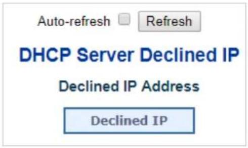
Figure 4-2-4-6: DHCP server Declined IP Page Screenshot
The page includes the following fields:
| Object Description | |
| • Delined IP | Display List of IP addresses declined. |
Buttons
Auto-refresh : Check this box to refresh the page automatically Refresh : Click to refresh the page immediately.
4.2.4.7 DHCP Detail Statistics
This page provides statistics for DHCP snooping. Notice that the normal forward per-port TX statistics isn't increased if the incoming DHCP packet is done by L3 forwarding mechanism. And clear the statistics on specific port may not take effect on global statistics since it gathers the different layer overview. screen in Figure 4-2-4-7 appears.
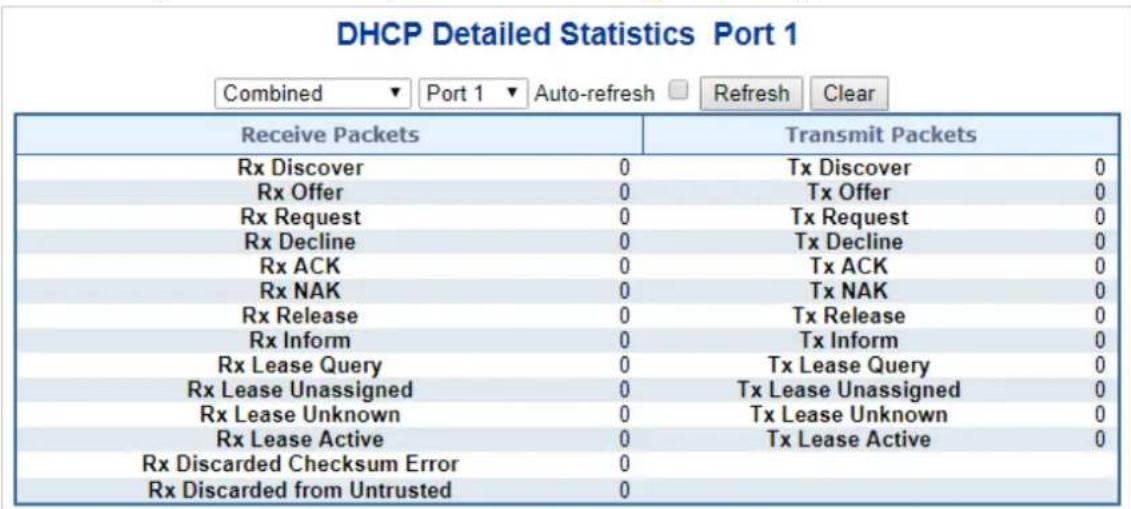
Figure 4-2-4-7: DHCP Detail Statistics page Screenshot
The page includes the following fields:
| Object Description | |
| Rx and Tx Discover | Display the number of discover (option 53 with value 1) packets received and transmitted. |
| Rx and Tx Offer | Display the number of offer (option 53 with value 2) packets received and transmitted. |
| Rx and Tx Request | Display the number of request (option 53 with value 3) packets received and transmitted |
| Rx and Tx Decline | Display the number of decline (option 53 with value 4) packets received and transmitted. |
| Rx and Tx ACK | Display the number of ACK (option 53 with value 5) packets received and transmitted. |
| Rx and Tx NAK | Display the number of NAK (option 53 with value 6) packets received and transmitted. |
| Rx and Tx Release | Display the number of release (option 53 with value 7) packets received and transmitted. |
| Rx and Tx Inform | Display the number of inform (option 53 with value 8) packets received and transmitted |
| Rx and Tx Lease Query | Display the number of lease query (option 53 with value 10) packets received and transmitted. |
| Rx and Tx Lease Unassigned | Display the number of lease unassigned (option 53 with value 11) packets received and transmitted. |
| Rx and Tx Lease Unknown | Display the number of lease unknown (option 53 with value 12) packets received and transmitted. |
| Rx and Tx Lease Active | Display the number of lease active (option 53 with value 13) packets received and transmitted |
| Rx Discarded checksum error | Display the number of discard packet that IP/UDP checksum is error. |
| Rx Discarded from Untrusted | Display the number of discarded packet that are coming from untrusted port. |
Buttons
Auto-refresh

: Check this box to refresh the page automatically
Refresh
Click to refresh the page immediately.
Clear
Clears the counters for the selected ports
4.2.5 Remote Management
The Managed Metro Switch support both NMS controleer and CloudViewer Sever for remote management. PLANET's NMS Controller is a Network Management System can monitor all kinds of deployed network devices, such as Managed Metro Switches, media converters, routers, smart APs, VoIP phones, IP cameras, etc., compliant with the SNMP Protocol, ONVIF Protocol and PLANET Smart Discovery utility. The CloudViewer is a free networking service just for PLANET Products. This service provides simplified network monitoring and real-time network status. Working with PLANET CloudViewer app, user can easily check network status, device information, Port status from Internet. Any other services are not included.
The Remote NMS Configuration screens in Figure 4-2-5-1 appear.
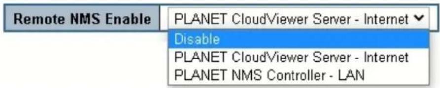
Figure 4-2-5-1: Remote NMS Configuration page Screenshot
The page includes the following fields:
| Object Description | |
| • Remote NMS Enable | Enable the remote NMS controller management.■ Disable.■ CloudViewer Server – Internet■ NMS Controller – LAN |
The NMS Controller – LAN Configuration screens in Figure 4-2-5-2 appear.
PLANET NMS Controller - LAN
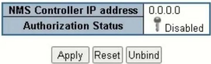
Figure 4-2-5-2: Remote NMS Configuration page Screenshot
The page includes the following fields:
| Object Description | |
| • NMS Controller IP address | The IP address of remote NMS controller. |
| • Authorization status | Displays the authorization status status for NMS controller, which can be one of the following:■ Unauthorized : The switch is unauthorized for NMS controller.■ Successful : the switch is authorized for NMS controller■ Failed : The authorization of NMS controller is failed.■ Disabled : The function of remote NMS management is disabled. |
The CloudViewer Server – Internet screens in Figure 4-2-5-3 appear.
PLANET CloudViewer Server - Internet
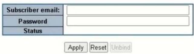
Figure 4-2-5-3: CloudViewer Server – Internet Configuration Page Screenshot
The page includes the following fields:
| Object Description | |
| • Subscriber email | The email registered on CloudViewer Server. |
| • Password | The password of your CloudViewer account. |
| • Status | Indicate the status of connecting CloudViewer Server. |
4.3 Switching
4.3.1 Port Management
Use the Port Menu to display or configure the Managed Metro Switch's ports. This section has the following items:
■ Port Configuration Configures port connection settings
■ Port Statistics Overview Lists Ethernet and RMON port statistics
■ Port Statistics Detail Lists Ethernet and RMON port statistics
■ SFP Module Information Display SFP information
■ Port Mirror Sets the source and target ports for mirroring
■ Name Map This page display Interface name to port number map
Many Web pages use a port number to express an interface, whereas CLI uses interface names. The table on this page provides a means to convert from one to the other.
4.3.1.1 Port Configuration
This page displays current port configurations. Ports can also be configured here. The Port Configuration screen in Figure 4-3-1-1 appears.
Port Configuration
| Port | Port Description | Link | Speed | Adv Duplex | Adv speed | Flow Control | Maximum Frame Size | Excessive Collision Mode | ||||||
| Current | Configured | Fdx | Hdx | 10M | 100M | 1G | Enable | Curr Rx | Curr Tx | |||||
| * | <All>✓ | ☐ | ☐ | ☐ | ☐ | ☐ | ☐ | 9600 | <All>✓ | |||||
| 1 | 1Gfdx Fiber | Auto✓ | ✓ | ✓ | ☐ | ✓ | ✓ | ☐ | ✘ | ✘ | 9600 | |||
| 2 | Down | Auto✓ | ✓ | ✓ | ☐ | ✓ | ✓ | ☐ | ✘ | ✘ | 9600 | |||
| 3 | Down | Auto✓ | ✓ | ✓ | ☐ | ✓ | ✓ | ☐ | ✘ | ✘ | 9600 | |||
| 4 | Down | Auto✓ | ✓ | ✓ | ☐ | ✓ | ✓ | ☐ | ✘ | ✘ | 9600 | |||
| 5 | Down | Auto✓ | ✓ | ✓ | ☐ | ✓ | ✓ | ☐ | ✘ | ✘ | 9600 | |||
| 6 | Down | Auto✓ | ✓ | ✓ | ☐ | ✓ | ✓ | ☐ | ✘ | ✘ | 9600 | |||
| 7 | Down | Auto✓ | ✓ | ✓ | ☐ | ✓ | ✓ | ☐ | ✘ | ✘ | 9600 | |||
| 8 | Down | Auto✓ | ✓ | ✓ | ☐ | ✓ | ✓ | ☐ | ✘ | ✘ | 9600 | |||
| 9 | Down | Auto✓ | ✓ | ✓ | ✓ | ✓ | ✓ | ☐ | ✘ | ✘ | 9600 | |||
Figure 4-3-1-1: Port Configuration Page Screenshot
The page includes the following fields:
| Object Description | |
| • Port | This is the logical port number for this row. |
| • Port Description | Indicates the per port description. |
| • Link | The current link state is displayed graphically. Green indicates the link is up and red indicates the link is down. |
| • Current Link Speed | Provides the current link speed of the port. |
| Configured Link Speed | Select any available link speed for the given switch port. Draw the menu bar to select the mode.■ Auto – Set up Auto negotiation for copper interface.■ 10Mbps HDX - Force sets 10Mbps/Half-Duplex mode.■ 10Mbps FDX - Force sets 10Mbps/Full-Duplex mode.■ 100Mbps HDX - Force sets 100Mbps/Half-Duplex mode.■ 100Mbps FDX - Force sets 100Mbps/Full-Duplex mode.■ 1Gbps FDX - Force sets 1000Mbps/Full-Duplex mode.■ 2.5Gbps FDX - Force sets 2500Mbps/Full-Duplex mode.■ Disable – Shut down the port manually. |
| Flow Control | When Auto Speed is selected on a port, this section indicates the flow control capability that is advertised to the link partner.When a fixed-speed setting is selected, that is what is used. The Current Rx column indicates whether pause frames on the port are obeyed, and the Current Tx column indicates whether pause frames on the port are transmitted. The Rx and Tx settings are determined by the result of the last Auto-Negotiation.Check the configured column to use flow control. This setting is related to the setting for Configured Link Speed. |
| Maximum Frame Size | Enter the maximum frame size allowed for the switch port, including FCS. The allowed range is 1518 bytes to 9600 bytes. |
| Excessive Collision Mode | Configure port transmit collision behavior.Discard: Discard frame after 16 collisions (default).Restart: Restart backoff algorithm after 16 collisions. |

When setting each port to run at 100M Full-, 100M Half-, 10M Full-, and 10M Half-speed modes. The Auto-MDIX function will disable.
Buttons
Apply
: Click to apply changes
Reset
: Click to undo any changes made locally and revert to previously saved values.
Refresh
Click to refresh the page. Any changes made locally will be undone.
4.3.1.2 Port Statistics Overview
This page provides an overview of general traffic statistics for all switch ports. The Port Statistics Overview screen in Figure
4-3-1-2 appears.
Port Statistics Overview
| Port | Packets | Bytes | Errors | Drops | Filtered | ||||
| Received | Transmitted | Received | Transmitted | Received | Transmitted | Received | Transmitted | Received | |
| 1 | 1076 | 1047 | 158972 | 862468 | 0 | 0 | 0 | 0 | 0 |
| 2 | 0 | 0 | 0 | 0 | 0 | 0 | 0 | 0 | 0 |
| 3 | 0 | 0 | 0 | 0 | 0 | 0 | 0 | 0 | 0 |
| 4 | 0 | 0 | 0 | 0 | 0 | 0 | 0 | 0 | 0 |
| 5 | 0 | 0 | 0 | 0 | 0 | 0 | 0 | 0 | 0 |
| 6 | 0 | 0 | 0 | 0 | 0 | 0 | 0 | 0 | 0 |
| 7 | 0 | 0 | 0 | 0 | 0 | 0 | 0 | 0 | 0 |
| 8 | 0 | 0 | 0 | 0 | 0 | 0 | 0 | 0 | 0 |
Figure 4-3-1-2: Port Statistics Overview Page Screenshot
The displayed counters are:
| Object Description | |
| • Port | The logical port for the settings contained in the same row. |
| • Packets | The number of received and transmitted packets per port. |
| • Bytes | The number of received and transmitted bytes per port. |
| • Errors | The number of frames received in error and the number of incomplete transmissions per port. |
| • Drops | The number of frames discarded due to ingress or egress congestion. |
| • Filtered | The number of received frames filtered by the forwarding process. |
Buttons
Download
Download the Port Statistics Overview result in EXCEL file.
Refresh
Click to refresh the page immediately.
Clear
: Clears the counters for all ports.
Print the Port Statistics Overview result.
Auto-refresh

Check this box to enable an automatic refresh of the page at regular intervals.
4.3.1.3 Port Statistics Detail
This page provides detailed traffic statistics for a specific switch port. Use the port select box to select which switch port details to display. The displayed counters are the totals for receive and transmit, the size counters for receive and transmit, and the error counters for receive and transmit. The Detailed Port Statistics screen in Figure 4-3-1-3 appears.
Detailed Port Statistics Port 1
| Receive Total | Transmit Total | ||
| Rx Packets | 2335 | Tx Packets | 2066 |
| Rx Octets | 431172 | Tx Octets | 1531131 |
| Rx Unicast | 2039 | Tx Unicast | 2050 |
| Rx Multicast | 48 | Tx Multicast | 11 |
| Rx Broadcast | 248 | Tx Broadcast | 5 |
| Rx Pause | 0 | Tx Pause | 0 |
| Receive Size Counters | Transmit Size Counters | ||
| Rx 64 Bytes | 1465 | Tx 64 Bytes | 242 |
| Rx 65-127 Bytes | 175 | Tx 65-127 Bytes | 53 |
| Rx 128-255 Bytes | 66 | Tx 128-255 Bytes | 523 |
| Rx 256-511 Bytes | 553 | Tx 256-511 Bytes | 203 |
| Rx 512-1023 Bytes | 76 | Tx 512-1023 Bytes | 284 |
| Rx 1024-1526 Bytes | 0 | Tx 1024-1526 Bytes | 761 |
| Rx 1527- Bytes | 0 | Tx 1527- Bytes | 0 |
| Receive Queue Counters | Transmit Queue Counters | ||
| Rx 00 | 2283 | Tx 00 | 0 |
| Rx 01 | 0 | Tx 01 | 0 |
| Rx 02 | 0 | Tx 02 | 0 |
| Rx 03 | 0 | Tx 03 | 0 |
| Rx 04 | 0 | Tx 04 | 0 |
| Rx 05 | 0 | Tx 05 | 0 |
| Rx 06 | 0 | Tx 06 | 0 |
| Rx 07 | 0 | Tx 07 | 2066 |
| Receive Error Counters | Transmit Error Counters | ||
| Rx Drops | 52 | Tx Drops | 0 |
| Rx CRC/Alignment | 0 | Tx Late/Exc. Coll. | 0 |
| Rx Undersize | 0 | ||
| Rx Oversize | 0 | ||
| Rx Fragments | 0 | ||
| Rx Jabber | 0 | ||
| Rx Filtered | 52 | ||
Figure 4-3-1-3: Detailed Port Statistics Port 1 Page Screenshot
The page includes the following fields:
Receive Total and Transmit Total
| Object Description | |
| • Rx and Tx Packets | The number of received and transmitted (good and bad) packets |
| • Rx and Tx Octets | The number of received and transmitted (good and bad) bytes, including FCS, but excluding framing bits. |
| • Rx and Tx Unicast | The number of received and transmitted (good and bad) unicast packets. |
| • Rx and Tx Multicast | The number of received and transmitted (good and bad) multicast packets. |
| • Rx and Tx Broadcast | The number of received and transmitted (good and bad) broadcast packets. |
| • Rx and Tx Pause | A count of the MAC Control frames received or transmitted on this port that has an opcode indicating a PAUSE operation. |
Receive and Transmit Size Counters
The number of received and transmitted (good and bad) packets split into categories based on their respective frame sizes.
Receive and Transmit Queue Counters
The number of received and transmitted packets per input and output queue.
Receive Error Counters
| Object Description | |
| • Rx Drops | The number of frames dropped due to lack of receive buffers or egress congestion. |
| • Rx CRC/Alignment | The number of frames received with CRC or alignment errors. |
| • Rx Undersize | The number of short frames received with valid CRC. |
| • Rx Oversize | The number of long frames received with valid CRC. |
| • Rx Fragments | The number of short frames received with invalid CRC. |
| • Rx Jabber | The number of long frames received with invalid CRC. |
| • Rx Filtered | The number of received frames filtered by the forwarding process.Short frames are frames that are smaller than 64 bytes.Long frames are frames that are longer than the configured maximum frame length for this port. |

1 Short frames are frames that are smaller than 64 bytes.
2 Long frames are frames that are longer than the configured maximum frame length for this port.
Transmit Error Counters
| Object Description | |
| • Tx Drops | The number of frames dropped due to output buffer congestion. |
| • Tx Late/Exc. Coll. | The number of frames dropped due to excessive or late collisions. |
Buttons
Auto-refresh ☐: Check this box to enable an automatic refresh of the page at regular intervals.
4.3.1.4 SFP Module Information
The Managed Metro Switches have supported the SFP module with digital diagnostics monitoring (DDM) function. This feature is also known as digital optical monitoring (DOM). You can check the physical or operational status of an SFP module via the SFP Module Information page.
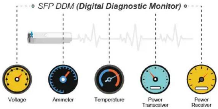
flowchart
graph LR
    A["SFP DDM (Digital Diagnostic Monitor)"] --> B["Voltage"]
    A --> C["Ammeter"]
    A --> D["Temperature"]
    A --> E["Power Transceiver"]
    A --> F["Power Receiver"]
This page shows the operational status, such as the transceiver type, speed, wavelength, optical output power, optical input power, temperature, laser bias current and transceiver supply voltage in real time. You can also use the hyperlink of port no. to check the statistics on a specific interface. The SFP Module Information screen in Figure 4-3-1-4 appears.
SFP Module Information
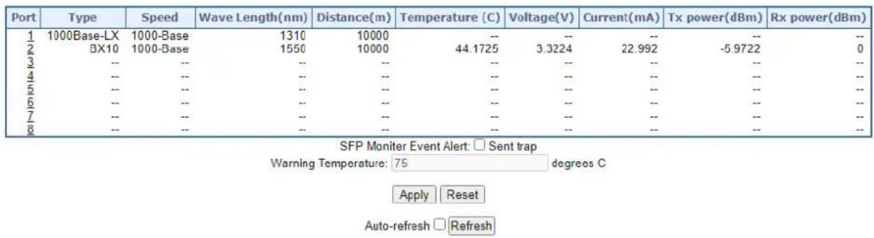
Figure 4-3-1-4: SFP Module Information for Switch Page Screenshot
The page includes the following fields:
| Object Description | |
| • Type | Display the type of current SFP module; the possible types are:Port 1 to port 6:■ 1000BASE-SX■ 1000BASE-LX■ 100BASE-FXPort 7 to port 8:■ 2500BASE-X■ 1000BASE-SX■ 1000BASE-LX■ 100BASE-FX |
| • Speed | Display the speed of current SFP module; the speed value or description is got from the SFP module. Different vendors SFP modules might show different speed information. |
| • Wave Length (nm) | Display the wavelength of current SFP module; the wavelength value is got from the SFP module. Use this column to check if the wavelength values of two nodes are matched while the fiber connection failed. |
| • Distance (m) | Display the support distance of current SFP module; the distance value is got from the SFP module. |
| • Temperature (C)– SFP DDM Module Only | Display the temperature of current SFP DDM module; the temperature value is got from the SFP DDM module. |
| • Voltage(V)– SFP DDM Module Only | Display the voltage of current SFP DDM module; the voltage value is got from the SFP DDM module. |
| • Current(mA)– SFP DDM Module Only | Display the Ampere of current SFP DDM module; the Ampere value is got from the SFP DDM module. |
| • TX power (dBm)– SFP DDM Module Only | Display the TX power of current SFP DDM module; the TX power value is got from the SFP DDM module. |
| • RX power (dBm)– SFP DDM Module Only | Display the RX power of current SFP DDM module; the RX power value is got from the SFP DDM module. |
Buttons
SFP Monitor Event Alert: □ send trap.
Warning Temperature: 75 degrees C.
Check SFP Monitor Event Alert box; it will be in accordance with your warning temperature setting and allows users to record message out via SNMP Trap.
Auto-refresh ☐ : Check this box to enable an automatic refresh of the page at regular intervals.
Apply
: Click to apply changes.
Reset
: Click to undo any changes made locally and revert to previously saved values.
Refresh
: Click to refresh the page immediately.
4.3.1.5 Port Mirror
Configure port Mirroring on this page. This function provides monitoring network traffic that forwards a copy of each incoming or outgoing packet from one port of a network Switch to another port where the packet can be studied. It enables the manager to keep close track of switch performance and alter it if necessary.
- To debug network problems, selected traffic can be copied, or mirrored, to a mirror port where a frame analyzer can be attached to analyze the frame flow.
- The Managed Metro Switch can unobtrusively mirror traffic from any port to a monitor port. You can then attach a protocol analyzer or RMON probe to this port to perform traffic analysis and verify connection integrity.
Port Mirror Application
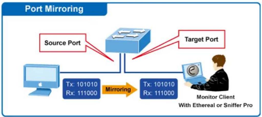
flowchart
graph TD
    A["Source Port"] --> B["Router"]
    C["Target Port"] --> B
    D["Monitor Client With Ethereal or Sniffer Pro"] --> E["Tx: 101010 Rx: 111000"]
    B --> F["Mirroring"]
    F --> E
Figure 4-3-1-5: Port Mirror Application
The traffic to be copied to the mirror port is selected as follows:
- All frames received on a given port (also known as ingress or source mirroring).
- All frames transmitted on a given port (also known as egress or destination mirroring).
Mirror Port Configuration
The Port Mirror screen in Figure 4-3-1-6 appears.and click the session ID to Figure 4-3-1-7
Mirror & RMirror Configuration Table
| Refresh | ||||
| Session ID | Mode | Type | VLAN ID | Reflector Port |
| 1 | Disabled | Mirror | - | - |
| 2 | Disabled | Mirror | - | - |
| 3 | Disabled | Mirror | - | - |
| 4 | Disabled | Mirror | - | - |
| 5 | Disabled | Mirror | - | - |
Figure 4-3-1-6: Mirror Configuration Page Screenshot
Mirror & RMirror Configuration
Global Settings
| Session ID | 1 | ▼ |
| Mode | Disabled | ▼ |
| Type | Mirror | ▼ |
| VLAN ID | 200 | |
| ReflectorPort | Port 1 | ▼ |
Source VLAN(s) Configuration

Port Configuration
| Port | Source | Destination |
| * | ||
| Port 1 | Disabled ▼ | |
| Port 2 | Disabled ▼ | |
| Port 3 | Disabled ▼ | |
| Port 4 | Disabled ▼ | |
| Port 5 | Disabled ▼ | |
| Port 6 | Disabled ▼ | |
| Port 7 | Disabled ▼ | |
| Port 8 | Disabled ▼ | |
| Port 9 | Disabled ▼ | |
| Port 10 | Disabled ▼ | |
| CPU | Disabled ▼ |

Figure 4-3-1-7: Mirror Configuration Page Screenshot
The page includes the following fields:
| Object Description | |
| • Session | Select session id to configure. |
| • Mode | To Enabled/Disabled the mirror or Remote Mirroring function |
| • Type | MirrorThe switch is running on mirror mode.The source port(s) and destination port are located on this switch.SourceThe switch is a source node for monitor flow.The source port(s), reflector port are located on this switch.RMirror destinationThe switch is an end node for monitor flow.The destination port(s) is located on this switch. |
| • VLAN ID | The VLAN ID points out where the monitor packet will copy to. The default VLAN ID is 200. |
| • Reflector Port | The reflector port is a method to redirect the traffic to Remote Mirroring VLAN. Any device connected to a port set as a reflector port loses connectivity until the Remote Mirroring isdisabled.In the stacking mode, you need to select switch ID to select the correct device.If you shut down a port, it cannot be a candidate for reflector port.If you shut down the port which is a reflector port, the remote mirror function cannot work |
| • Source VLAN(s)Configuration | The switch can supports VLAN-based Mirroring. If you want to monitor some VLANs on the switch, you can set the selected VLANs on this field. |
| • Remote MirroringPort Configuration | The following table is used for port role selecting.■ Port: The logical port for the settings contained in the same row..■ Source: Select mirror mode.Disabled Neither frames transmitted nor frames received are mirrored.Both Frames received and frames transmitted are mirrored on the Destination port.Rx only Frames received on this port are mirrored on the Destination port.Frames transmitted are not mirrored.Tx only Frames transmitted on this port are mirrored on the Destination port.Frames received are not mirrored■ Destination: Select destination port.This checkbox is designed for mirror or Remote Mirroring.Thedestination portis a switched port that you receive a copy of traffic from the source port. |

For a given port, a frame is only transmitted once. It is therefore not possible to mirror Tx frames on the mirror port. Because of this, mode for the selected mirror port is limited to Disabled or Rx only.
Buttons
Save
Click to apply changes
Reset
: Click to undo any changes made locally and revert to previously saved values.
4.3.1.6 Name Map
Display port namp map this page. Many Web pages use a port number to express an interface, whereas CLI uses interface names. The table on this page provides a means to convert from one to the other.
Interface Name to Port Number Map
| Interface Name | Port Number |
| Gi 1/1 | 1 |
| Gi 1/2 | 2 |
| Gi 1/3 | 3 |
| Gi 1/4 | 4 |
| Gi 1/5 | 5 |
| Gi 1/6 | 6 |
| 2.5G 1/1 | 7 |
| 2.5G 1/2 | 8 |
| Gi 1/7 | 9 |
| Gi 1/8 | 10 |
Figure 4-3-1-8: Namp Map Page Screenshot
The page includes the following fields:
| Object Description | |
| • Interface Name | Display per port interface name. |
| • Mode | Display per port number. |
4.3.2 Link Aggregation
Port Aggregation optimizes port usage by linking a group of ports together to form a single Link Aggregated Groups (LAGs). Port Aggregation multiplies the bandwidth between the devices, increases port flexibility, and provides link redundancy.
Each LAG is composed of ports of the same speed, set to full-duplex operations. Ports in a LAG, can be of different media types (UTP/Fiber, or different fiber types), provided they operate at the same speed.
Aggregated Links can be assigned manually (Port Trunk) or automatically by enabling Link Aggregation Control Protocol (LACP) on the relevant links.
Aggregated Links are treated by the system as a single logical port. Specifically, the Aggregated Link has similar port attributes to a non-aggregated port, including auto-negotiation, speed, Duplex setting, etc.
The device supports the following Aggregation links :
■ Static LAGs (Port Trunk) – Force aggregated selected ports to be a trunk group.
■ Link Aggregation Control Protocol (LACP) LAGs - LACP LAG negotiate Aggregated Port links with other LACP ports located on a different device. If the other device ports are also LACP ports, the devices establish a LAG between them.
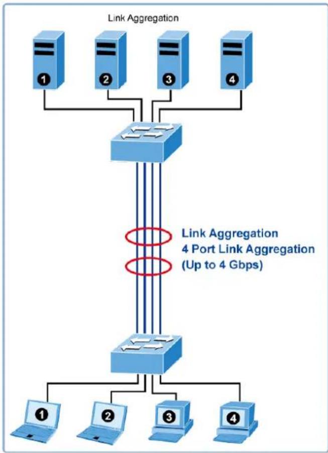
flowchart
graph TD
    A["1"] --> B["Router"]
    C["2"] --> B
    D["3"] --> B
    E["4"] --> B
    B --> F["Router"]
    F --> G["1"]
    F --> H["2"]
    F --> I["3"]
    F --> J["4"]
    style B fill:#f9f,stroke:#333
    note right of F Link Aggregation: Link Aggregation 4 Port Link Aggregation (Up to 4 Gbps)
Figure 4-3-2-1: Link Aggregation
The Link Aggregation Control Protocol (LACP) provides a standardized means for exchanging information between Partner Systems that require high speed redundant links. Link aggregation lets you group up to eight consecutive ports into a single dedicated connection. This feature can expand bandwidth to a device on the network. LACP operation requires full-duplex mode, more detail information refer to the IEEE 802.3ad standard.
Port link aggregations can be used to increase the bandwidth of a network connection or to ensure fault recovery. Link aggregation lets you group up to 4 consecutive ports into a single dedicated connection between any two the Switch or other Layer 2 switches. However, before making any physical connections between devices, use the Link aggregation Configuration menu to specify the link aggregation on the devices at both ends. When using a port link aggregation, note that:
- The ports used in a link aggregation must all be of the same media type (RJ45, 100 Mbps fiber).
- The ports that can be assigned to the same link aggregation have certain other restrictions (see below).
- Ports can only be assigned to one link aggregation.
- The ports at both ends of a connection must be configured as link aggregation ports.
- None of the ports in a link aggregation can be configured as a mirror source port or a mirror target port.
- All of the ports in a link aggregation have to be treated as a whole when moved from/to, added or deleted from a VLAN.
- The Spanning Tree Protocol will treat all the ports in a link aggregation as a whole.
- Enable the link aggregation prior to connecting any cable between the switches to avoid creating a data loop.
- Disconnect all link aggregation port cables or disable the link aggregation ports before removing a port link aggregation to avoid creating a data loop.
It allows a maximum of 10 ports to be aggregated at the same time. The Managed Metro Switch support Gigabit Ethernet ports (up to 5 groups). If the group is defined as a LACP static link aggregation group, then any extra ports selected are placed in a standby mode for redundancy if one of the other ports fails. If the group is defined as a local static link aggregation group, then the number of ports must be the same as the group member ports.
The aggregation code ensures that frames belonging to the same frame flow (for example, a TCP connection) are always forwarded on the same link aggregation member port. Recording of frames within a flow is therefore not possible. The aggregation code is based on the following information:
- Source MAC
- Destination MAC
• Source and destination IPv4 address. - Source and destination TCP/UDP ports for IPv4 packets
Normally, all 5 contributions to the aggregation code should be enabled to obtain the best traffic distribution among the link aggregation member ports. Each link aggregation may consist of up to 10 member ports. Any quantity of link aggregation s may be configured for the device (only limited by the quantity of ports on the device.) To configure a proper traffic distribution, the ports within a link aggregation must use the same link speed.
4.3.2.1 Common Aggregation Configuration
This page is used to configure the Aggregation hash mode and the aggregation group. The aggregation hash mode settings are global.
Hash Code Contributors
The Static Aggregation screen in Figure 4-3-2-2 appears.
Common Aggregation Configuration
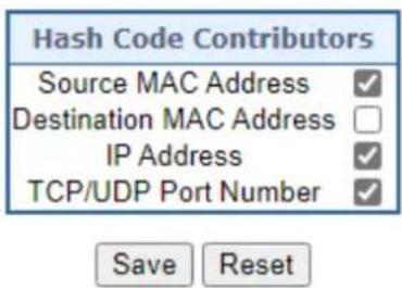
Figure 4-3-2-2 : Aggregation Mode Configuration Page Screenshot
The page includes the following fields:
| Object Description | |
| • Source MAC Address | The Source MAC address can be used to calculate the destination port for the frame. Check to enable the use of the Source MAC address, or uncheck to disable. By default, Source MAC Address is enabled. |
| • Destination MAC Address | The Destination MAC Address can be used to calculate the destination port for the frame. Check to enable the use of the Destination MAC Address, or uncheck to disable. By default, Destination MAC Address is disabled. |
| • IP Address | The IP address can be used to calculate the destination port for the frame. Check to enable the use of the IP Address, or uncheck to disable. By default, IP Address is enabled. |
| • TCP/UDP Port Number | The TCP/UDP port number can be used to calculate the destination port for the frame. Check to enable the use of the TCP/UDP Port Number, or uncheck to disable. By default, TCP/UDP Port Number is enabled. |
4.3.2.2 Static Aggregation Group Configuration
The Aggregation Group Configuration screen in Figure 4-3-2-3 appears.
Aggregation Group Configuration
| Port Members | Group Configuration | ||||||||||||
| Group ID | 1 | 2 | 3 | 4 | 5 | 6 | 7 | 8 | 9 | 10 | Mode | Revertive | Max Bundle |
| Normal | |||||||||||||
| 1 | Disabled | √ | 10 | ||||||||||
| 2 | Disabled | √ | 10 | ||||||||||
| 3 | Disabled | √ | 10 | ||||||||||
| 4 | Disabled | √ | 10 | ||||||||||
| 5 | Disabled | √ | 10 | ||||||||||
Save Reset
Figure 4-3-2-3: Aggregation Group Configuration Page Screenshot
The page includes the following fields:
| .Object | Description |
| • Group ID | Indicates the group ID for the settings contained in the same row. Group ID "Normal" indicates there is no aggregation. Only one group ID is valid per port. |
| • Port Members | Each switch port is listed for each group ID. Select a radio button to include a port in an aggregation, or clear the radio button to remove the port from the aggregation. By default, no ports belong to any aggregation group. |
| • Mode | This parameter determines the mode for the aggregation group.• Disabled: The group is disabled.• Static: The group operates in static aggregation mode.• LACP (Active): The group operates in LACP active aggregation mode. See IEEE 801.AX-2014, section 6.4.1 for details.• LACP (Passive): The group operates in LACP passive aggregation mode. See IEEE 801.AX-2014, section 6.4.1 for details. |
| • Revertive | This parameter only applies to LACP-enabled groups. It determines if the group will perform automatic link (re-)calculation when links with higher priority becomes available. |
| • Max Bundle | This parameter only applies to LACP-enabled groups. It determines the maximum number of active bundled LACP ports allowed in an aggregation. |
Buttons
Apply
: Click to apply changes
4.3.2.3 Static Aggregation Status
This page is used to see the status of ports in Aggregation group. The Static Aggregation Status screen in Figure 4-3-2-4 appears.
| Aggr ID | Name | Type | Speed | Configured Ports | Aggregated Ports |
| No aggregation groups | |||||
Figure 4-3-2-4 : LACP Port Configuration Page Screenshot
The page includes the following fields:
| Object Description | |
| • Aggr ID | Display the Aggregation ID associated with this aggregation instance. |
| • Name | Display the Name of the Aggregation group ID. |
| • Type | Display the type of the Aggregation group(Static or LACP). |
| • Speed | Display the Speed of the Aggregation group. |
| • Configured Ports | Display the Configured member ports of the Aggregation group. |
| • Aggregated Ports | Display the Aggregated member ports of the Aggregation group. |
Buttons
Refresh
Click to refresh the page immediately.
Auto-refresh ☐: Automatic refresh occurs every 3 seconds.
4.3.2.4 LACP Configuration
Link Aggregation Control Protocol (LACP) - LACP LAG negotiate Aggregated Port links with other LACP ports located on a different device. LACP allows switches connected to each other to discover automatically whether any ports are member of the same LAG.
This page allows the user to inspect the current LACP port configurations, and possibly change them as well. The LACP Configuration screen in Figure 4-3-2-5 appears.
LACP System Configuration

LACP Port Configuration
| Port | LACP | Timeout | Priority |
| * | ✓ | 32768 | |
| 1 | No | Fast ✓ | 32768 |
| 2 | No | Fast ✓ | 32768 |
| 3 | No | Fast ✓ | 32768 |
| 4 | No | Fast ✓ | 32768 |
| 5 | No | Fast ✓ | 32768 |
| 6 | No | Fast ✓ | 32768 |
| 7 | No | Fast ✓ | 32768 |
| 8 | No | Fast ✓ | 32768 |
| 9 | No | Fast ✓ | 32768 |
| 10 | No | Fast ✓ | 32768 |
Figure 4-3-2-5 : LACP Port Configuration Page Screenshot
The page includes the following fields:
| Object Description | |
| • Port | The switch port number. |
| • LACP Enabled | Controls whether LACP is enabled on this switch port. LACP will form an aggregation when 2 or more ports are connected to the same partner. |
| • Timeout | The Timeout controls the period between BPDU transmissions. Fast will transmit LACP packets each second, while Slow will wait for 30 seconds before sending a LACP packet. |
| • Priority | The Priority controls the priority of the port. If the LACP partner wants to form a larger group than is supported by this device then this parameter will control which ports will be active and which ports will be in a backup role. Lower number means greater priority. |
Buttons
: Click to apply changes
: Click to undo any changes made locally and revert to previously saved values.
4.3.2.5 LACP System Status
This page provides a status overview of all LACP instances. The LACP Status Page displays the current LACP aggregation Groups and LACP Port status. The LACP System Status screen in Figure 4-3-2-6 appears.
LACP System Status
Local System ID
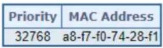
Partner System Status
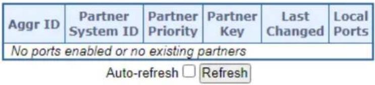
Figure 4-3-2-6: LACP System Status Page Screenshot
The page includes the following fields:
| Object Description | |
| Local System ID | |
| • Priority | The priority information display here. |
| • MAC Address | The switch MAC address information display here. |
| Partner System Status | |
| • Aggr ID | The Aggregation ID associated with this aggregation instance.For LLAG the id is shown as 'isid:aggr-id' and for GLAGs as 'aggr-id' |
| • Partner System ID | The system ID (MAC address) of the aggregation partner. |
| • Partner Priority | The priority of the aggregation partner. |
| • Partner Key | The Key that the partner has assigned to this aggregation ID. |
| • Last Changed | The time since this aggregation changed. |
| • Local Ports | Shows which ports are a part of this aggregation for this switch. |
Buttons
Refresh
Click to refresh the page immediately.
Auto-refresh ☐: Automatic refresh occurs every 3 seconds.
4.3.2.6 LACP Internal Status
This page provides a status overview of LACP status for all ports. The LACP Internal Port Status screen in Figure 4-3-2-7 appears.

Figure 4-3-2-7: LACP Status Page Screenshot
The page includes the following fields:
| Object Description | |
| • Port | The switch port number. |
| • State | The current port state:● Down: The port is not active.● Active: The port is in active state.● Standby: The port is in standby state. |
| • Key | The key assigned to this port. Only ports with the same key can aggregate together. |
| • Priority | The priority assigned to this aggregation group. |
| • Activity | The LACP mode of the group (Active or Passive). |
| • Timeout | The timeout mode configured for the port (Fast or Slow). |
| • Aggregation | Show whether the system considers this link to be "aggregateable"; i.e., a potential candidate for aggregation. |
| • Synchronization | Show whether the system considers this link to be "IN_SYNC"; i.e., it has been allocated to the correct LAG, the group has been associated with a compatible Aggregator, and the identity of the LAG is consistent with the System ID and operational Key information transmitted. |
| • Collecting | Show if collection of incoming frames on this link is enabled. |
| • Distributing | Show if distribution of outgoing frames on this link is enabled. |
| • Defaulted | Show if the Actor's Receive machine is using Defaulted operational Partner information. |
| • Expired | Show if that the Actor's Receive machine is in the EXPIRED state. |
Buttons
Refresh
Click to refresh the page immediately.
Auto-refresh ☐: Automatic refresh occurs every 3 seconds.
4.3.2.7 LACP Neighbor Port Status
This page provides a status overview of LACP status for all ports. The LACP Neighbor Port Status screen in Figure 4-3-2-8 appears.

Figure 4-3-2-8: LACP Neighbor Port Status Page Screenshot
The page includes the following fields:
| Object Description | |
| • Port | The switch port number. |
| • State | The current port state:● Down: The port is not active.● Active: The port is in active state.● Standby: The port is in standby state. |
| • Aggr ID | The aggregation group ID which the port is assigned to. |
| • Partner Key | The key assigned to this port by the partner. |
| • Partner Port | The partner port number associated with this link. |
| • Partner Port Prio | The priority assigned to this partner port . |
| • Activity | The LACP mode of the group (Active or Passive). |
| • Timeout | The timeout mode configured for the port (Fast or Slow). |
| • Aggregation | Show whether the system considers this link to be "aggregateable"; i.e., a potential candidate for aggregation. |
| • Synchronization | Show whether the system considers this link to be "IN_SYNC"; i.e., it has been allocated to the correct LAG, the group has been associated with a compatible Aggregator, and the identity of the LAG is consistent with the System ID and operational Key information transmitted. |
| • Collecting | Show if collection of incoming frames on this link is enabled. |
| • Distributing | Show if distribution of outgoing frames on this link is enabled. |
| • Defaulted | Show if the Actor's Receive machine is using Defaulted operational Partner information. |
| • Expired | Show if that the Actor's Receive machine is in the EXPIRED state. |
Buttons
Refresh
Click to refresh the page immediately.
Auto-refresh ☐: Automatic refresh occurs every 3 seconds.
4.3.2.8 LACP Port Statistics
This page provides an overview for LACP statistics for all ports. The LACP Port Status screen in Figure 4-3-2-9 appears.
LACP Statistics
| Port | LACP Received | LACP Transmitted | Discarded | |
| Unknown | Illegal | |||
| 1 | 0 | 0 | 0 | 0 |
| 2 | 0 | 0 | 0 | 0 |
| 3 | 0 | 0 | 0 | 0 |
| 4 | 0 | 0 | 0 | 0 |
| 5 | 0 | 0 | 0 | 0 |
| 6 | 0 | 0 | 0 | 0 |
| 7 | 0 | 0 | 0 | 0 |
| 8 | 0 | 0 | 0 | 0 |
| 9 | 0 | 0 | 0 | 0 |
| 10 | 0 | 0 | 0 | 0 |
Figure 4-3-2-9: LACP Port Statistics Page Screenshot
The page includes the following fields:
| Object Description | |
| • Port | The switch port number. |
| • LACP Received | Shows how many LACP frames have been received at each port. |
| • LACP Transmitted | Shows how many LACP frames have been sent from each port. |
| • Discarded | Shows how many unknown or illegal LACP frames have been discarded at each port. |
Buttons
Auto-refresh ☐: Automatic refresh occurs every 3 seconds.
Refresh
Click to refresh the page immediately.
Clear
: Clears the counters for all ports.
4.3.3 VLAN
4.3.3.1 VLAN Overview
A Virtual Local Area Network (VLAN) is a network topology configured according to a logical scheme rather than the physical layout. VLAN can be used to combine any collection of LAN segments into an autonomous user group that appears as a single LAN. VLAN also logically segment the network into different broadcast domains so that packets are forwarded only between ports within the VLAN. Typically, a VLAN corresponds to a particular subnet, although not necessarily.
VLAN can enhance performance by conserving bandwidth, and improve security by limiting traffic to specific domains.
A VLAN is a collection of end nodes grouped by logic instead of physical location. End nodes that frequently communicate with each other are assigned to the same VLAN, regardless of where they are physically on the network. Logically, a VLAN can be equated to a broadcast domain, because broadcast packets are forwarded to only members of the VLAN on which the broadcast was initiated.

- No matter what basis is used to uniquely identify end nodes and assign these nodes VLAN membership, packets cannot cross VLAN without a network device performing a routing function between the VLANs.
- The Managed Metro Switch supports IEEE 802.1Q VLAN. The port untagging function can be used to remove the 802.1 tag from packet headers to maintain compatibility with devices that are tag-unaware..

The Managed Metro Switch 's default is to assign all ports to a single 802.1Q VLAN named DEFAULT_VLAN. As new VLAN is created, the member ports assigned to the new VLAN will be removed from the DEFAULT_VLAN port member list. The DEFAULT_VLAN has a VID = 1.
This section has the following items:
■ VLAN Port Configuration Enables VLAN group
■ VLAN Membership Status Displays VLAN membership status
■ VLAN Port Status Displays VLAN port status
■ Private VLAN Creates/removes primary or community VLANs
■ Port Isolation Enables/disablse port isolation on port
■ MAC-based VLAN Configures the MAC-based VLAN entries
■ IP Subnet based VLAN Configures the IP Subnet based VLAN entries
■ Protocol-based VLAN Configures the protocol-based VLAN entries
■ Protocol-based VLAN Displays the protocol-based VLAN entries
Membership
4.3.3.2 IEEE 802.1Q VLAN
In large networks, routers are used to isolate broadcast traffic for each subnet into separate domains. This Managed Metro Switch provides a similar service at Layer 2 by using VLANs to organize any group of network nodes into separate broadcast domains. VLANs confine broadcast traffic to the originating group, and can eliminate broadcast storms in large networks. This also provides a more secure and cleaner network environment.
An IEEE 802.1Q VLAN is a group of ports that can be located anywhere in the network, but communicate as though they belong to the same physical segment.
VLANs help to simplify network management by allowing you to move devices to a new VLAN without having to change any physical connections. VLANs can be easily organized to reflect departmental groups (such as Marketing or R&D), usage groups (such as e-mail), or multicast groups (used for multimedia applications such as videoconferencing).
VLANs provide greater network efficiency by reducing broadcast traffic, and allow you to make network changes without having to update IP addresses or IP subnets. VLANs inherently provide a high level of network security since traffic must pass through a configured Layer 3 link to reach a different VLAN.
This Managed Metro Switch supports the following VLAN features:
■ Up to 4K VLANs based on the IEEE 802.1Q standard
■ Port overlapping, allowing a port to participate in multiple VLANs
■ End stations can belong to multiple VLANs
■ Passing traffic between VLAN-aware and VLAN-unaware devices
■ Priority tagging
IEEE 802.1Q Standard
IEEE 802.1Q (tagged) VLAN are implemented on the Switch. 802.1Q VLAN require tagging, which enables them to span the entire network (assuming all switches on the network are IEEE 802.1Q-compliant).
VLAN allow a network to be segmented in order to reduce the size of broadcast domains. All packets entering a VLAN will only be forwarded to the stations (over IEEE 802.1Q enabled switches) that are members of that VLAN, and this includes broadcast, multicast and unicast packets from unknown sources.
VLAN can also provide a level of security to your network. IEEE 802.1Q VLAN will only deliver packets between stations that are members of the VLAN. Any port can be configured as either tagging or untagging.:
■ The untagging feature of IEEE 802.1Q VLAN allows VLAN to work with legacy switches that don't recognize VLAN tags in packet headers.
■ The tagging feature allows VLAN to span multiple 802.1Q-compliant switches through a single physical connection and allows Spanning Tree to be enabled on all ports and work normally.
Some relevant terms:
- Tagging - The act of putting 802.1Q VLAN information into the header of a packet.
- Untagging - The act of stripping 802.1Q VLAN information out of the packet header.
802.1Q VLAN Tags
The figure below shows the 802.1Q VLAN tag. There are four additional octets inserted after the source MAC address. Their presence is indicated by a value of 0x8100 in the Ether Type field. When a packet's Ether Type field is equal to 0x8100, the packet carries the IEEE 802.1Q/802.1p tag. The tag is contained in the following two octets and consists of 3 bits of user priority, 1 bit of Canonical Format Identifier (CFI - used for encapsulating Token Ring packets so they can be carried across Ethernet backbones), and 12 bits of VLAN ID (VID). The 3 bits of user priority are used by 802.1p. The VID is the VLAN identifier and is used by the 802.1Q standard. Because the VID is 12 bits long, 4094 unique VLAN can be identified.
The tag is inserted into the packet header making the entire packet longer by 4 octets. All of the information originally contained in the packet is retained.
802.1Q Tag
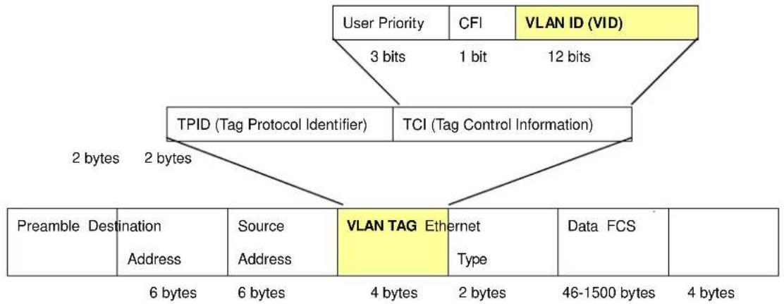
flowchart
graph TD
    A["User Priority"] --> B["3 bits"]
    C["CFI"] --> D["1 bit"]
    E["VLAN ID (VID)"] --> F["12 bits"]
    B --> G["TPID (Tag Protocol Identifier)"]
    D --> G
    F --> H["TCI (Tag Control Information)"]
    G --> I["2 bytes"]
    H --> I
    I --> J["Preamble Destination"]
    I --> K["Source Address"]
    I --> L["VLAN TAG Ethernet Type"]
    L --> M["6 bytes"]
    L --> N["6 bytes"]
    L --> O["4 bytes"]
    L --> P["2 bytes"]
    L --> Q["46-1500 bytes"]
    L --> R["4 bytes"]
The Ether Type and VLAN ID are inserted after the MAC source address, but before the original Ether Type/Length or Logical Link Control. Because the packet is now a bit longer than it was originally, the Cyclic Redundancy Check (CRC) must be recalculated.
Adding an IEEE802.1Q Tag
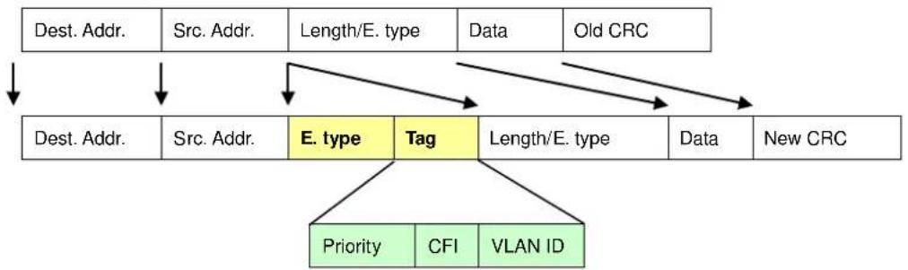
flowchart
graph TD
    A["Dest. Addr."] --> B["Src. Addr."]
    B --> C["Length/E. type"]
    C --> D["Data"]
    D --> E["Old CRC"]
    E --> F["End"]
    G["Dest. Addr."] --> H["Src. Addr."]
    H --> I["E. type"]
    I --> J["Tag"]
    J --> K["Length/E. type"]
    K --> L["Data"]
    L --> M["New CRC"]
    M --> N["Priority"]
    M --> O["CFI"]
    M --> P["VLAN ID"]
Port VLAN ID
Packets that are tagged (are carrying the 802.1Q VID information) can be transmitted from one 802.1Q compliant network device to another with the VLAN information intact. This allows 802.1Q VLAN to span network devices (and indeed, the entire network – if all network devices are 802.1Q compliant).
Every physical port on a switch has a PVID. 802.1Q ports are also assigned a PVID, for use within the switch. If no VLAN are defined on the switch, all ports are then assigned to a default VLAN with a PVID equal to 1. Untagged packets are assigned the
PVID of the port on which they were received. Forwarding decisions are based upon this PVID, in so far as VLAN are concerned. Tagged packets are forwarded according to the VID contained within the tag. Tagged packets are also assigned a PVID, but the PVID is not used to make packet forwarding decisions, the VID is.
Tag-aware switches must keep a table to relate PVID within the switch to VID on the network. The switch will compare the VID of a packet to be transmitted to the VID of the port that is to transmit the packet. If the two VID are different the switch will drop the packet. Because of the existence of the PVID for untagged packets and the VID for tagged packets, tag-aware and tag-unaware network devices can coexist on the same network.
A switch port can have only one PVID, but can have as many VID as the switch has memory in its VLAN table to store them.
Because some devices on a network may be tag-unaware, a decision must be made at each port on a tag-aware device before packets are transmitted – should the packet to be transmitted have a tag or not? If the transmitting port is connected to a tag-unaware device, the packet should be untagged. If the transmitting port is connected to a tag-aware device, the packet should be tagged.
Default VLANs
The Switch initially configures one VLAN, VID = 1, called "default." The factory default setting assigns all ports on the Switch to the "default". As new VLAN are configured in Port-based mode, their respective member ports are removed from the "default."
- Assigning Ports to VLANs
Before enabling VLANs for the switch, you must first assign each port to the VLAN group(s) in which it will participate. By default all ports are assigned to VLAN 1 as untagged ports. Add a port as a tagged port if you want it to carry traffic for one or more VLANs, and any intermediate network devices or the host at the other end of the connection supports VLANs. Then assign ports on the other VLAN-aware network devices along the path that will carry this traffic to the same VLAN(s), either manually or dynamically using GVRP. However, if you want a port on this switch to participate in one or more VLANs, but none of the intermediate network devices nor the host at the other end of the connection supports VLANs, then you should add this port to the VLAN as an untagged port.

VLAN-tagged frames can pass through VLAN-aware or VLAN-unaware network interconnection devices, but the VLAN tags should be stripped off before passing it on to any end-node host that does not support VLAN tagging.
VLAN Classification
When the switch receives a frame, it classifies the frame in one of two ways. If the frame is untagged, the switch assigns the frame to an associated VLAN (based on the default VLAN ID of the receiving port). But if the frame is tagged, the switch uses the tagged VLAN ID to identify the port broadcast domain of the frame.
Port Overlapping
Port overlapping can be used to allow access to commonly shared network resources among different VLAN groups, such as file servers or printers. Note that if you implement VLANs which do not overlap, but still need to communicate, you can connect them by enabled routing on this switch.
■ Untagged VLANs
Untagged (or static) VLANs are typically used to reduce broadcast traffic and to increase security. A group of network users assigned to a VLAN form a broadcast domain that is separate from other VLANs configured on the switch. Packets are forwarded only between ports that are designated for the same VLAN. Untagged VLANs can be used to manually isolate user groups or subnets.
IEEE 802.1Q Tunneling (Q-in-Q)
IEEE 802.1Q Tunneling (Q-in-Q) is designed for service providers carrying traffic for multiple customers across their networks. Q-in-Q tunneling is used to maintain customer-specific VLAN and Layer 2 protocol configurations even when different customers use the same internal VLAN IDs. This is accomplished by inserting Service Provider VLAN (SPVLAN) tags into the customer's frames when they enter the service provider's network, and then stripping the tags when the frames leave the network.
A service provider's customers may have specific requirements for their internal VLAN IDs and number of VLANs supported. VLAN ranges required by different customers in the same service-provider network might easily overlap, and traffic passing through the infrastructure might be mixed. Assigning a unique range of VLAN IDs to each customer would restrict customer configurations, require intensive processing of VLAN mapping tables, and could easily exceed the maximum VLAN limit of 4096.
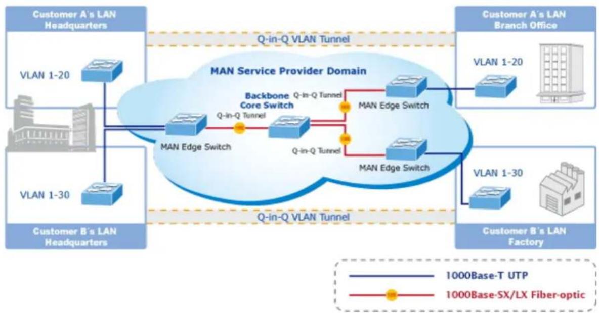
flowchart
graph TD
    subgraph_Customer_A_s_LAN_Headquarters["Customer A's LAN Headquarters"]
        A1["VLAN 1-20"] --> B1["MAN Edge Switch"]
        A2["VLAN 1-30"] --> B2["MAN Edge Switch"]
    end

    subgraph_Customer_B_s_LAN_Headquarters["Customer B's LAN Headquarters"]
        B1 --> C1["MAN Edge Switch"]
        B2 --> C2["MAN Edge Switch"]
    end

    subgraph_Customer_B_s_LAN_Factory["Customer B's LAN Factory"]
        C1 --> D1["MAN Edge Switch"]
        C2 --> D2["MAN Edge Switch"]
    end

    B1 -->|Q-in-Q Tunnel| C1
    B2 -->|Q-in-Q Tunnel| C2

    style B1 fill:#cce5ff,stroke:#333
    style B2 fill:#cce5ff,stroke:#333
    style C1 fill:#cce5ff,stroke:#333
    style C2 fill:#cce5ff,stroke:#333
    linkStyle 0 stroke:#000,stroke-width:2px
    linkStyle 1 stroke:#000,stroke-width:2px
    linkStyle 2 stroke:#000,stroke-width:2px
    linkStyle 3 stroke:#000,stroke-width:2px
    linkStyle 4 stroke:#000,stroke-width:2px
    linkStyle 5 stroke:#000,stroke-width:2px
    linkStyle 6 stroke:#000,stroke-width:2px
    linkStyle 7 stroke:#000,stroke-width:2px
    linkStyle 8 stroke:#000,stroke-width:2px
    linkStyle 9 stroke:#000,stroke-width:2px
    linkStyle 10 stroke:#000,stroke-width:2px
    linkStyle 11 stroke:#000,stroke-width:2px
    linkStyle 12 stroke:#000,stroke-width:2px
    linkStyle 13 stroke:#000,stroke-width:2px
    linkStyle 14 stroke:#000,stroke-width:2px
    linkStyle 15 stroke:#000,stroke-width:2px
    linkStyle 16 stroke:#000,stroke-width:2px
    linkStyle 17 stroke:#000,stroke-width:2px
    linkStyle 18 stroke:#000,stroke-width:2px
    linkStyle 19 stroke:#000,stroke-width:2px
    linkStyle 20 stroke:#000,stroke-width:2px
    linkStyle 21 stroke:#000,stroke-width:2px
    linkStyle 22 stroke:#000,stroke-width:2px
    linkStyle 23 stroke:#000,stroke-width:2px
    linkStyle 24 stroke:#000,stroke-width:2px
    linkStyle 25 stroke:#000,stroke-width:2px
    linkStyle 26 stroke:#000,stroke-width:2px
    linkStyle 27 stroke:#000,stroke-width:2px
    linkStyle 28 stroke:#000,stroke-width:2px
    linkStyle 29 stroke:#000,stroke-width:2px
    linkStyle 30 stroke:#000,stroke-width:2px
    linkStyle 31 stroke:#000,stroke-width:2px
    linkStyle 32 stroke:#000,stroke-width:2px
    linkStyle 33 stroke:#000,stroke-width:2px
    linkStyle 34 stroke:#000,stroke-width:2px
    linkStyle 35 stroke:#000,stroke-width:2px
    linkStyle 36 stroke:#000,stroke-width:2px
    linkStyle 37 stroke:#000,stroke-width:2px
    linkStyle 38 stroke:#000,stroke-width:2px
    linkStyle 39 stroke:#000,stroke-width:2px
    linkStyle 40 stroke:#000,stroke-width:2px
    linkStyle 41 stroke:#000,stroke-width:2px
    linkStyle 42 stroke:#000,stroke-width:2px
    linkStyle 43 stroke:#000,stroke-width:2px
    linkStyle 44 stroke:#000,stroke-width:2px
    linkStyle 45 stroke:#000,stroke-width:2px
    linkStyle 46 stroke:#000,stroke-width:2px
    linkStyle 47 stroke:#000,stroke-width:2px
    linkStyle 48 stroke:#000,stroke-width:2px
    linkStyle 49 stroke:#000,stroke-width:2px
    linkStyle 50 stroke:#000,stroke-width:2px
The Managed Metro Switch supports multiple VLAN tags and can therefore be used in MAN applications as a provider bridge, aggregating traffic from numerous independent customer LANs into the MAN (Metro Access Network) space. One of the purposes of the provider bridge is to recognize and use VLAN tags so that the VLANs in the MAN space can be used independent of the customers' VLANs. This is accomplished by adding a VLAN tag with a MAN-related VID for frames entering the MAN. When leaving the MAN, the tag is stripped and the original VLAN tag with the customer-related VID is again available.
This provides a tunneling mechanism to connect remote costumer VLANs through a common MAN space without interfering with the VLAN tags. All tags use EtherType 0x8100 or 0x88A8, where 0x8100 is used for customer tags and 0x88A8 are used for service provider tags.
In cases where a given service VLAN only has two member ports on the switch, the learning can be disabled for the particular VLAN and can therefore rely on flooding as the forwarding mechanism between the two ports. This way, the MAC table requirements is reduced.
4.3.3.3 VLAN Port Configuration
This page is used for configuring the Managed Metro Switch port VLAN. The VLAN per Port Configuration page contains fields for managing ports that are part of a VLAN. The port default VLAN ID (PVID) is configured on the VLAN Port Configuration page. All untagged packets arriving to the device are tagged by the ports PVID.
Understand nomenclature of the Switch
IEEE 802.1Q Tagged and Untagged
Every port on an 802.1Q compliant switch can be configured as tagged or untagged.
- Tagged:
Ports with tagging enabled will put the VID number, priority and other VLAN information into the header of all packets that flow into those ports. If a packet has previously been tagged, the port will not alter the packet, thus keeping the VLAN information intact. The VLAN information in the tag can then be used by other 802.1Q compliant devices on the network to make packet-forwarding decisions. - Untagged: Ports with untagging enabled will strip the 802.1Q tag from all packets that flow into those ports. If the packet doesn't have an 802.1Q VLAN tag, the port will not alter the packet. Thus, all packets received by and forwarded by an untagging port will have no 802.1Q VLAN information. (Remember that the PVID is only used internally within the Switch). Untagging is used to send packets from an 802.1Q-compliant network device to a non-compliant network device.
| Frame IncomeFrame Leave | Income Frame is tagged | Income Frame is untagged |
| Leave port is tagged | Frame remains tagged | Tag is inserted |
| Leave port is untagged | Tag is removed | Frame remain untagged |
Table 4-3-3-1: Ingress / Egress Port with VLAN VID Tag / Untag Table
Global VLAN Configuration
The Global VLAN Configuration screen in Figure 4-3-3-1 appears.
| Global VLAN Configuration | |
| Allowed Access VLANs | 1 |
| Ethertype for Custom S-ports | 88A8 |
Figure 4-3-3-1 : Global VLAN Configuration Screenshot
The page includes the following fields:
| Object Description | |
| • Allowed Access VLANs | This field shows the allowed Access VLANs, it only affects ports configured as Access ports. Ports in other modes are members of all VLANs specified in the Allowed VLANs field.By default, only VLAN 1 is enabled. More VLANs may be created by using a list syntax where the individual elements are separated by commas. Ranges are specified with a dash separating the lower and upper bound.The following example will create VLANs 1, 10, 11, 12, 13, 200, and 300: 1, 10–13, 200, 300. Spaces are allowed in between the delimiters. |
| • Ethertype for Custom S-ports | This field specifies the ethertype/TPID (specified in hexadecimal) used for Custom S-ports. The setting is in force for all ports whose Port Type is set to S-Custom-Port. |
Port VLAN Configuration
The VLAN Port Configuration screen in Figure 4-3-3-2 appears.
Port VLAN Configuration
| Port | Mode | Port VLAN | Port Type | Ingress Filtering | Ingress Acceptance | Egress Tagging | Allowed VLANs | Forbidden VLANs |
| * | 1 | 1 | ||||||
| 1 | Access | C-Port | Tagged and Untagged | Untag Port VLAN | ||||
| 2 | Access | C-Port | Tagged and Untagged | Untag Port VLAN | ||||
| 3 | Access | C-Port | Tagged and Untagged | Untag Port VLAN | ||||
| 4 | Access | C-Port | Tagged and Untagged | Untag Port VLAN | ||||
| 5 | Access | C-Port | Tagged and Untagged | Untag Port VLAN | ||||
| 6 | Access | C-Port | Tagged and Untagged | Untag Port VLAN | ||||
| 7 | Access | C-Port | Tagged and Untagged | Untag Port VLAN | ||||
| 8 | Access | C-Port | Tagged and Untagged | Untag Port VLAN |
Figure 4-3-3-2 : Port VLAN Configuration Screenshot
The page includes the following fields:
| Object Description | ||
| • Port | This is the logical port number for this row. | |
| • Mode | Access | Access ports are normally used to connect to end stations. Dynamic features like Voice VLAN may add the port to more VLANs behind the scenes. Access ports have the following characteristics:• Member of exactly one VLAN, the Port VLAN (Access VLAN), which by default is 1Accepts untagged and C-tagged framesDiscards all frames that are not classified to the Access VLANOn egress all frames classified to the Access VLAN are transmitted untagged. Other (dynamically added VLANs) are transmitted tagged |
| Trunk | Trunk ports can carry traffic on multiple VLANs simultaneously, and are normally used to connect to other switches. Trunk ports have the following characteristics:By default, a trunk port is member of all VLANs (1-4095)The VLANs that a trunk port is member of may be limited by the use of Allowed VLANsFrames classified to a VLAN that the port is not a member of are discardedBy default, all frames but frames classified to the Port VLAN (a.k.a. Native VLAN) get tagged on egress. Frames classified to the Port VLAN do not get C-tagged on egressEgress tagging can be changed to tag all frames, in which case only tagged frames are accepted on ingress | |
| Hybrid | Hybrid ports resemble trunk ports in many ways, but adds additional port configuration features. In addition to the characteristics described for trunk ports, hybrid ports have these abilities:Can be configured to be VLAN tag unaware, C-tag aware, S-tag aware, or S-custom-tag awareIngress filtering can be controlledIngress acceptance of frames and configuration of egress tagging can be configured independently | |
| • Port VLAN | Determines the port's VLAN ID (PVID). Allowed VLANs are in the range 1 through 4095, default being 1.On ingress, frames get classified to the Port VLAN if the port is configured as VLAN unaware, the frame is untagged, or VLAN awareness is enabled on the port, but the frame is priority tagged (VLAN ID = 0).On egress, frames classified to the Port VLAN do not get tagged if Egress Tagging configuration is set to untag Port VLAN.The Port VLAN is called an "Access VLAN" for ports in Access mode and Native VLAN for ports in Trunk or Hybrid mode. | |
| • Port Type | Ports in hybrid mode allow for changing the port type, that is, whether a frame's VLAN tag is used to classify the frame on ingress to a particular VLAN, and if so, which TPID it reacts on. Likewise, on egress, the Port Type determines the TPID of the tag, if a tag is required.Unaware:On ingress, all frames, whether carrying a VLAN tag or not, get classified to the Port VLAN, and possible tags are not removed on egress. | |
| ■ C-Port:On ingress, frames with a VLAN tag with TPID = 0x8100 get classified to the VLAN ID embedded in the tag. If a frame is untagged or priority tagged, the frame gets classified to the Port VLAN. If frames must be tagged on egress, they will be tagged with a C-tag.■ S-Port:On ingress, frames with a VLAN tag with TPID = 0x8100 or 0x88A8 get classified to the VLAN ID embedded in the tag. If a frame is untagged or priority tagged, the frame gets classified to the Port VLAN. If frames must be tagged on egress, they will be tagged with an S-tag.■ S-Custom-Port:On ingress, frames with a VLAN tag with a TPID = 0x8100 or equal to the Ethertype configured for Custom-S ports get classified to the VLAN ID embedded in the tag. If a frame is untagged or priority tagged, the frame gets classified to the Port VLAN. If frames must be tagged on egress, they will be tagged with the custom S-tag. | ||
| • Ingress Filtering | Hybrid ports allow for changing ingress filtering. Access and Trunk ports always have ingress filtering enabled.■ If ingress filtering is enabled (checkbox is checked), frames classified to a VLAN that the port is not a member of get discarded.■ If ingress filtering is disabled, frames classified to a VLAN that the port is not a member of are accepted and forwarded to the switch engine.However, the port will never transmit frames classified to VLANs that it is not a member of. | |
| • Ingress Acceptance | Hybrid ports allow for changing the type of frames that are accepted on ingress.■ Tagged and UntaggedBoth tagged and untagged frames are accepted.■ Tagged OnlyOnly tagged frames are accepted on ingress. Untagged frames are discarded.■ Untagged OnlyOnly untagged frames are accepted on ingress. Tagged frames are discarded. | |
| Egress Tagging | This option is only available for ports in Hybrid mode. Ports in Trunk and Hybrid mode may control the tagging of frames on egress.■ Untag Port VLANFrames classified to the Port VLAN are transmitted untagged. Other frames are transmitted with the relevant tag.■ Tag AllAll frames, whether classified to the Port VLAN or not, are transmitted with a tag.■ Untag AllAll frames, whether classified to the Port VLAN or not, are transmitted without a tag. | |
| • Allowed VLANs | Ports in Trunk and Hybrid mode may control which VLANs they are allowed to become members of. The field's syntax is identical to the syntax used in the Enabled VLANs field.By default, a Trunk or Hybrid port will become member of all VLANs, and is therefore set to 1-4095. The field may be left empty, which means that the port will not become member of any VLANs. | |
| • Forbidden VLANs | A port may be configured to never be member of one or more VLANs. This is particularly useful when dynamic VLAN protocols like MVRP and GVRP must be prevented from dynamically adding ports to VLANs. The trick is to mark such VLANs as forbidden on the port in question. The syntax is identical to the syntax used in the Enabled VLANs field.By default, the field is left blank, which means that the port may become a member of all possible VLANs. | |

The port must be a member of the same VLAN as the Port VLAN ID.
Buttons
Apply
: Click to apply changes
Reset
: Click to undo any changes made locally and revert to previously saved values.
4.3.3.4 VLAN Membership Status
This page provides an overview of membership status for VLAN users. The VLAN Membership Status screen in Figure 4-3-3-3 appears.
VLAN Membership Status for Combined users


| Port Members | ||||||||||
| VLAN ID | 1 | 2 | 3 | 4 | 5 | 6 | 7 | 8 | 9 | 10 |
| 1 | ✓ | ✓ | ✓ | ✓ | ✓ | ✓ | ✓ | ✓ | ✓ | ✓ |
Figure 4-3-3-3: VLAN Membership Status for Static User Page Screenshot
The page includes the following fields:
| Object Description | |
| • VLAN User | A VLAN User is a module that uses services of the VLAN management functionality to configure VLAN memberships and VLAN port configuration such as PVID, UVID. Currently we support following VLAN: - Admin: This is referred as static. - NAS: NAS provides port-based authentication, which involves communications between a Supplicant, Authenticator, and an Authentication Server. - GVRP: GVRP (GARP VLAN Registration Protocol or Generic VLAN Registration Protocol) is a protocol that facilitates control of virtual local area networks (VLANs) within a larger network. - Voice VLAN: Voice VLAN is a VLAN configured specially for voice traffic typically originating from IP phones. - MVR: MVR is used to eliminate the need to duplicate multicast traffic for subscribers in each VLAN. Multicast traffic for all channels is sent only on a single (multicast) VLAN. |
| • Port Members | A row of check boxes for each port is displayed for each VLAN ID. If a port is included in a VLAN, an image will be displayed. If a port is included in a Forbidden port list, an image will be displayed. If a port is included in a Forbidden port list and dynamic VLAN user register VLAN on same Forbidden port, then conflict port will be displayed as conflict port. |
| • VLAN Membership | The VLAN Membership Status page shall show the current VLAN port members for all VLANs configured by a selected VLAN User (selection shall be allowed by a Combo Box). When ALL VLAN Users are selected, it shall show this information for all the VLAN Users, and this is by default. VLAN membershipallows the frames classified to the VLAN ID to be forwarded on the respective VLAN member ports. |
Buttons
: Select VLAN Users from this drop down list.
Auto-refresh ☐: Check this box to refresh the page automatically. Automatic refresh occurs every 3 seconds.

Click to refresh the page immediately.

Updates the table starting from the first entry in the VLAN Table, i.e. the entry with the lowest VLAN ID.

Updates the table, starting with the entry after the last entry currently displayed.
4.3.3.5 VLAN Port Status
This page provides VLAN Port Status. The VLAN Port Status screen in Figure 4-3-3-4 appears.
VLAN Port Status for Combined users
| Combined Auto-refresh Refresh | |||||||
| Port | Port Type | Ingress Filtering | Frame Type | Port VLAN ID | Tx Tag | Untagged VLAN ID | Conflicts |
| 1 | C-Port | √ | All | 1 | Untag PVID | No | |
| 2 | C-Port | √ | All | 1 | Untag PVID | No | |
| 3 | C-Port | √ | All | 1 | Untag PVID | No | |
| 4 | C-Port | √ | All | 1 | Untag PVID | No | |
| 5 | C-Port | √ | All | 1 | Untag PVID | No | |
| 6 | C-Port | √ | All | 1 | Untag PVID | No | |
| 7 | C-Port | √ | All | 1 | Untag PVID | No | |
| √ | All | No | |||||
Figure 4-3-3-4: VLAN Port Status for Combined users Page Screenshot
The page includes the following fields:
| Object Description | |
| • Port | The logical port for the settings contained in the same row. |
| • Port Type | Show the VLAN Awareness for the port.If VLAN awareness is enabled, the tag is removed from tagged frames received on the port. VLAN tagged frames are classified to the VLAN ID in the tag.If VLAN awareness is disabled, all frames are classified to the Port VLAN ID and tags are not removed. |
| • Ingress Filtering | Show the ingress filtering for a port. This parameter affects VLAN ingress processing. If ingress filtering is enabled and the ingress port is not a member ofthe classified VLAN of the frame, the frame is discarded. |
| • Frame Type | Shows whether the port accepts all frames or only tagged frames. This parameter affects VLAN ingress processing. If the port only accepts tagged frames, untagged frames received on that port are discarded. |
| • Port VLAN ID | Shows the PVID setting for the port. |
| • Tx Tag | Shows egress filtering frame status whether tagged or untagged. |
| • Untagged VLAN ID | Shows UVID (untagged VLAN ID). Port's UVID determines the packet's behavior at the egress side. |
| • Conflicts | Shows status of Conflicts whether exists or Not. When a Volatile VLAN User requests to set VLAN membership or VLAN port configuration, the following conflicts can occur:■ Functional Conflicts between feature.■ Conflicts due to hardware limitation.■ Direct conflict between user modules. |
Buttons
Static

Select VLAN Users from this drop down list.
Auto-refresh ☐: Check this box to refresh the page automatically. Automatic refresh occurs every 3 seconds.
Refresh
Click to refresh the page immediately.
4.3.3.6 Private VLAN
The Private VLAN membership configurations for the switch can be monitored and modified here. Private VLANs can be added or deleted here. Port members of each Private VLAN can be added or removed here.
Private VLANs are based on the source port mask, and there are no connections to VLANs. This means that VLAN IDs and Private VLAN IDs can be identical.
A port must be a member of both a VLAN and a Private VLAN to be able to forward packets. By default, all ports are VLAN unaware and members of VLAN 1 and Private VLAN 1.
A VLAN unaware port can only be a member of one VLAN, but it can be a member of multiple Private VLANs. The VLAN Port Status screen in Figure 4-3-3-5 appears.
Auto-refresh □ Refresh
Private VLAN Membership Configuration
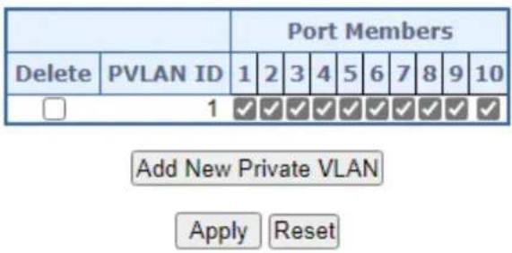
Figure 4-3-3-5: Private VLAN Membership Configuration page screenshot
The page includes the following fields:
| Object Description | |
| Delete | To delete a private VLAN entry, check this box. The entry will be deleted during the next save. |
| Private VLAN ID | Indicates the ID of this particular private VLAN. |
| Port Members | A row of check boxes for each port is displayed for each private VLAN ID. To include a port in a Private VLAN, check the box. To remove or exclude the port from the Private VLAN, make sure the box is unchecked. By default, no ports are members, and all boxes are unchecked. |
| Adding a New Private VLAN | Click “Add New Private VLAN” to add a new private VLAN ID. An empty row is added to the table, and the private VLAN can be configured as needed. The allowed range for a private VLAN ID is the same as the switch port number range. Any values outside this range are not accepted, and a warning message appears. Click "OK" to discard the incorrect entry, or click "Cancel" to return to the editing and make a correction.The Private VLAN is enabled when you click "Save".The “Delete” button can be used to undo the addition of new Private VLANs. |
Buttons
Add New Private VLAN : Click to add new VLAN.
Apply : Click to save changes.
Reset: Click to undo any changes made locally and revert to previously saved values.
Auto-refresh ☐: Check this box to refresh the page automatically. Automatic refresh occurs every 3 seconds.
Refresh: Click to refresh the page immediately.
4.3.3.7 Port Isolation
Overview
When a VLAN is configured to be a private VLAN, communication between ports within that VLAN can be prevented. Two application examples are provided in this section:
- Customers connected to an ISP can be members of the same VLAN, but they are not allowed to communicate with each other within that VLAN.
- Servers in a farm of web servers in a Demilitarized Zone (DMZ) are allowed to communicate with the outside world and with database servers on the inside segment, but are not allowed to communicate with each other
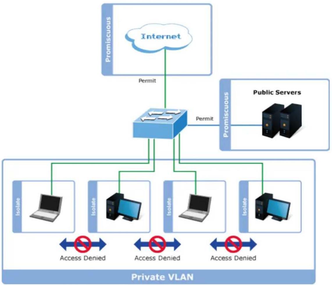
flowchart
graph TD
    A["Internet"] -->|Permit| B["Router"]
    C["Public Servers"] -->|Permit| B
    B --> D["Isolate"]
    B --> E["Isolate"]
    B --> F["Isolate"]
    B --> G["Isolate"]
    D <--> H["Access Denied"]
    E <--> I["Access Denied"]
    F <--> J["Access Denied"]
    G <--> K["Access Denied"]
    L["Private VLAN"] --> M["Isolate"]
    L --> N["Isolate"]
    L --> O["Isolate"]
    L --> P["Isolate"]
For private VLANs to be applied, the switch must first be configured for standard VLAN operation When this is in place, one or more of the configured VLANs can be configured as private VLANs. Ports in a private VLAN fall into one of these two groups:
■ Promiscuous ports
— Ports from which traffic can be forwarded to all ports in the private VLAN
— Ports which can receive traffic from all ports in the private VLAN
■ Isolated ports
— Ports from which traffic can only be forwarded to promiscuous ports in the private VLAN
— Ports which can receive traffic from only promiscuous ports in the private VLAN
The configuration of promiscuous and isolated ports applies to all private VLANs. When traffic comes in on a promiscuous port in a private VLAN, the VLAN mask from the VLAN table is applied. When traffic comes in on an isolated port, the private VLAN mask is applied in addition to the VLAN mask from the VLAN table. This reduces the ports to which forwarding can be done to just the promiscuous ports within the private VLAN.
This page is used for enabling or disabling port isolation on ports in a Private VLAN. A port member of a VLAN can be isolated to other isolated ports on the same VLAN and Private VLAN. The Port Isolation screen in Figure 4-3-3-6 appears.
Auto-refresh □ Refresh
Port Isolation Configuration
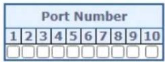

Figure 4-3-3-6: Port Isolation Configuration Page Screenshot
The page includes the following fields:
| Object Description | |
| • Port Member | A check box is provided for each port of a private VLAN. When checked, port isolation is enabled on that port. When unchecked, port isolation is disabled on that port.By default, port isolation isdisabledon all ports. |
Buttons
Apply
: Click to apply changes
Reset
: Click to undo any changes made locally and revert to previously saved values.
Auto-refresh ☐: Check this box to refresh the page automatically. Automatic refresh occurs every 3 seconds.
Refresh
Click to refresh the page immediately.
4.3.3.8 VLAN setting example:
Separate VLAN
802.1Q VLAN Trunk
Port Isolate
4.3.3.8.1 Two Separate 802.1Q VLANs
The diagram shows how the Managed Metro Switch handle Tagged and Untagged traffic flow for two VLANs. VLAN Group 2 and VLAN Group 3 are separated VLAN. Each VLAN isolate network traffic so only members of the VLAN receive traffic from the same VLAN members. The screen in Figure 4-3-3-7 appears and Table 4-3-3-8 describes the port configuration of the Managed Metro Switches.
VLAN Overview
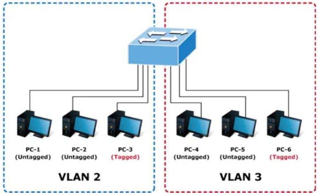
flowchart
graph TD
    subgraph VLAN 2
        PC1["PC-1 (Untagged)"]
        PC2["PC-2 (Untagged)"]
        PC3["PC-3 (Tagged)"]
    end
    subgraph VLAN 3
        PC4["PC-4 (Untagged)"]
        PC5["PC-5 (Untagged)"]
        PC6["PC-6 (Tagged)"]
    end
    PC1 --> PC2
    PC2 --> PC3
    PC3 --> PC4
    PC4 --> PC5
    PC5 --> PC6
    PC1 -.-> PC2
    PC2 -.-> PC3
    PC3 -.-> PC4
    PC4 -.-> PC5
    PC5 -.-> PC6
Figure 4-3-3-7: Two Separate VLANs Diagram
| VLAN Group | VID | Untagged Members | Tagged Members |
| VLAN Group 1 | 1 | Port-7 ~ Port-52 | N/A |
| VLAN Group 2 2 | Port-1,Port-2 | Port-3 | |
| VLAN Group 3 3 | Port-4,Port-5 | Port-6 |
Table 4-1: VLAN and Port Configuration
The scenario is described as follows:
■ Untagged packet entering VLAN 2
- While [PC-1] transmit an untagged packet enters Port-1, the Managed Metro Switch will tag it with a VLAN Tag=2. [PC-2] and [PC-3] will receive the packet through Port-2 and Port-3.
- [PC-4], [PC-5] and [PC-6] received no packet.
-
While the packet leaves Port-2, it will be stripped away it tag becoming an untagged packet.
-
While the packet leaves Port-3, it will keep as a tagged packet with VLAN Tag=2.
■ Tagged packet entering VLAN 2
-
While [PC-3] transmit a tagged packet with VLAN Tag=2 enters Port-3, [PC-1] and [PC-2] will receive the packet through Port-1 and Port-2.
-
While the packet leaves Port-1 and Port-2, it will be stripped away it tag becoming an untagged packet.
■ Untagged packet entering VLAN 3
-
While [PC-4] transmit an untagged packet enters Port-4, the switch will tag it with a VLAN Tag=3. [PC-5] and [PC-6] will receive the packet through Port-5 and Port-6.
-
While the packet leaves Port-5, it will be stripped away it tag becoming an untagged packet.
-
While the packet leaves Port-6, it will keep as a tagged packet with VLAN Tag=3.

For this example, VLAN Group 1 just set as default VLAN, but only focus on VLAN 2 and VLAN 3 traffic flow
Setup steps
1. Add VLAN Group
Add two VLANs – VLAN 2 and VLAN 3
Type 1-3 in Allowed Access VLANs column, the 1-3 is including VLAN1 and 2 and 3.

Figure 4-3-3-8: Add VLAN 2 and VLAN 3
2. Assign VLAN Member and PVID for each port:
VLAN 2 : Port-1, Port-2 and Port-3
| Allowed Access VLANs | 1-3 |
| Ethertype for Custom S-ports | 8848 |
Port VLAN Configuration
| Port | Mode | Port VLAN | Port Type | Ingress Filtering | Ingress Acceptance | Egress Tagging | Allowed VLANs | Forbidden VLANs | |||
| * | 2 | 2 | |||||||||
| 1 | Access | 2 | C-Port | ✓ | Tagged and Untagged | Untag Port VLAN | 2 | ||||
| 2 | Access | 2 | C-Port | ✓ | Tagged and Untagged | Untag Port VLAN | 2 | ||||
| 3 | Access | 2 | C-Port | ✓ | Tagged and Untagged | Untag Port VLAN | 2 | ||||
| 4 | Access | 3 | C-Port | ✓ | Tagged and Untagged | Untag Port VLAN | 3 | ||||
| 5 | Access | 3 | C-Port | ✓ | Tagged and Untagged | Untag Port VLAN | 3 | ||||
| 6 | Access | 3 | C-Port | ✓ | Tagged and Untagged | Untag Port VLAN | 3 | ||||
| 7 | Access | 1 | C-Port | ✓ | Tagged and Untagged | Untag Port VLAN | 1 | ||||
| 8 | Access | 1 | C-Port | ✓ | Tagged and Untagged | Untag Port VLAN | 1 | ||||
| 9 | Access | 1 | C-Port | ✓ | Tagged and Untagged | Untag Port VLAN | 1 | ||||
| 10. | Access | 1 | C-Port | ✓ | Tagged and Untagged | Untag Port VLAN | 1 | ||||
Figure 4-3-3-9: Change Port VLAN of Port 1\~3 to be VLAN2 and Port VLAN of Port 4\~6 to be VLAN3
3. Enable VLAN Tag for specific ports
Link Type: Port-3 (VLAN-2) and Port-6 (VLAN-3)
Change Port 3 Mode as Trunk, Selects Egress Tagging as Tag All and Types 2 in the Allowed VLANs column.
Change Port 6 Mode as Trunk and Selects Egress Tagging as Tag All and Types 3 in the Allowed VLANs column.
The Per Port VLAN configuration in Figure 4-3-3-10 appears.
Global VLAN Configuration
| Allowed Access VLANs | 1-3 |
| Ethertype for Custom S-ports | 8848 |
Port VLAN Configuration
| Port | Mode | Port VLAN | Port Type | Ingress Filtering | Ingress Acceptance | Egress Tagging | Allowed VLANs | Forbidden VLANs |
| * | 2 | 2 | ||||||
| 1 | Access | C-Port | Tagged and Untagged | Untag Port VLAN | 2 | |||
| 2 | Access | C-Port | Tagged and Untagged | Untag Port VLAN | 2 | |||
| 3 | Trunk | C-Port | Tagged Only | Tag All | 2 | |||
| 4 | Access | C-Port | Tagged and Untagged | Untag Port VLAN | 3 | |||
| 5 | Access | C-Port | Tagged and Untagged | Untag Port VLAN | 3 | |||
| 6 | Trunk | C-Port | Tagged Only | Tag All | 3 | |||
| 7 | Access | C-Port | Tagged and Untagged | Untag Port VLAN | 1 |
Figure 4-3-3-10: Check VLAN 2 and 3 Members on VLAN Membership Page
4.3.3.8.2 VLAN Trunking between two 802.1Q aware switches
The most cases are used for "Uplink" to other switches. VLANs are separated at different switches, but they need to access with other switches within the same VLAN group. The screen in Figure 4-3-3-11 appears.
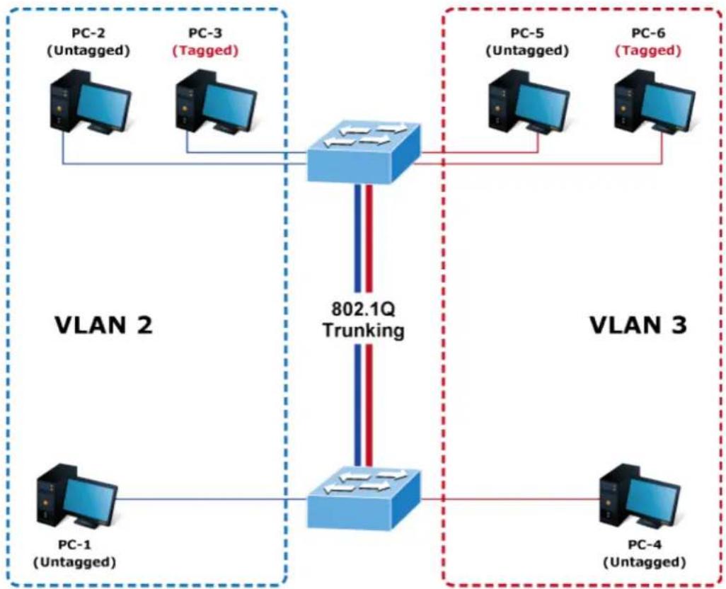
flowchart
graph TD
    subgraph VLAN 2
        PC1["PC-1 (Untagged)"] -->|blue arrow| Trunking["802.1Q Trunking"]
        PC2["PC-2 (Untagged)"] -->|blue arrow| Trunking
        PC3["PC-3 (Tagged)"] -->|blue arrow| Trunking
    end
    subgraph VLAN 3
        PC4["PC-4 (Untagged)"] -->|red arrow| Trunking
        PC5["PC-5 (Untagged)"] -->|red arrow| Trunking
        PC6["PC-6 (Tagged)"] -->|red arrow| Trunking
    end
    PC1 --> Trunking
    PC2 --> Trunking
    PC3 --> Trunking
    PC4 --> Trunking
    PC5 --> Trunking
    PC6 --> Trunking
Figure 4-3-3-11: VLAN Trunking Diagram
Setup steps
1. Add VLAN Group
Add two VLANs - VLAN 2 and VLAN 3
Type 1-3 in Allowed Access VLANs column, the 1-3 is including VLAN1 and 2 and 3.

Figure 4-3-3-12: Add VLAN 2 and VLAN 3
2. Assign VLAN Member and PVID for each port :
VLAN 2 : Port-1, Port-2 and Port-3
| Port VLAN Configuration | ||||||||
| Port | Mode | Port VLAN | Port Type | Ingress Filtering | Ingress Acceptance | Egress Tagging | Allowed VLANs | Forbidden VLANs |
| * | 2 | 2 | ||||||
| 1 | Access | 2 | C-Port | ✓ | Tagged and Untagged | Untag All | 1 | |
| 2 | Access | 2 | C-Port | ✓ | Tagged and Untagged | Untag All | 1 | |
| 3 | Access | 2 | C-Port | ✓ | Tagged and Untagged | Untag All | 1 | |
| 4 | Access | 2 | C-Port | ✓ | Tagged and Untagged | Untag All | 1 | |
| 5 | Access | 2 | C-Port | ✓ | Tagged and Untagged | Untag All | 1 | |
| 6 | Access | 2 | C-Port | ✓ | Tagged and Untagged | Untag All | 1 | |
| 7 | Access | 2 | C-Port | ✓ | Tagged and Untagged | Untag All | 1 | |
| 8 | Access | 2 | C-Port | ✓ | Tagged and Untagged | Untag All | 1 | |
| 9 | Access | 2 | C-Port | ✓ | Tagged and Untagged | Untag All | 1 | |
| 10 | Access | 2 | C-Port | ✓ | Tagged and Untagged | Untag All | 1 | |
Figure 4-3-3-13: Changes Port VLAN of Port 1\~3 to be VLAN2 and Port VLAN of Port 4\~6 to be VLAN3
For the VLAN ports connecting to the hosts, please refer to 4.6.10.1 examples. The following steps will focus on the VLAN Trunk port configuration.
- Specify Port-7 to be the 802.1Q VLAN Trunk port.
- Assign Port-7 to both VLAN 2 and VLAN 3 at the VLAN Member configuration page.
- Define a VLAN 1 as a "Public Area" that overlapping with both VLAN 2 members and VLAN 3 members.
- Assign the VLAN Trunk Port to be the member of each VLAN – which wants to be aggregated. For this example, add Port-7 to be VLAN 2 and VLAN 3 member port.
- Specify Port-7 to be the 802.1Q VLAN Trunk port, and the Trunking port must be a Tagged port while egress. The Port-7 configuration is shown in Figure 4-3-3-14.
| Global VLAN Configuration | ||||||||
| Allowed Access VLANs | 1-3 | |||||||
| Ethertype for Custom S-ports | 88A8 | |||||||
| Port VLAN Configuration | ||||||||
| Port | Mode | Port VLAN | Port Type | Ingress Filtering | Ingress Acceptance | Egress Tagging | Allowed VLANs | Forbidden VLANs |
| * | <All> | 2 | <All> | ☐ | <All> | <All> | 2 | 1 |
| 1 | Access | 2 | C-Port | ✓ | Tagged and Untagged | Untag Port VLAN | 2 | 1 |
| 2 | Access | 2 | C-Port | ✓ | Tagged and Untagged | Untag Port VLAN | 2 | 1 |
| 3 | Access | 2 | C-Port | ✓ | Tagged and Untagged | Untag Port VLAN | 2 | 1 |
| 4 | Access | 3 | C-Port | ✓ | Tagged and Untagged | Untag Port VLAN | 3 | 1 |
| 5 | Access | 3 | C-Port | ✓ | Tagged and Untagged | Untag Port VLAN | 3 | 1 |
| 6 | Access | 3 | C-Port | ✓ | Tagged and Untagged | Untag Port VLAN | 3 | 1 |
| 7 | Trunk | 1 | C-Port | ✓ | Tagged Only | Tag All | 1-3 | |
| 8 | Access | 1 | C-Port | ✓ | Tagged and Untagged | Untag Port VLAN | 1 | |
Figure 4-3-3-14: VLAN Overlap Port Setting & VLAN 1 – The Public Area Member Assign
That is, although the VLAN 2 members: Port-1 to Port-3 and VLAN 3 members: Port-4 to Port-6 also belongs to VLAN 1. But with different PVID settings, packets form VLAN 2 or VLAN 3 is not able to access to the other VLAN.
- Repeat Steps 1 to 6, set up the VLAN Trunk port at the partner switch and add more VLANs to join the VLAN trunk, repeat Steps 1 to 3 to assign the Trunk port to the VLANs.
4.3.3.8.3 Port Isolate
The diagram shows how the Managed Metro Switch handles isolated and promiscuous ports, and the each PC is not able to access the isolated port of each other's PCs. But they all need to access with the same server/AP/Printer. This section will show you how to configure the port for the server – that could be accessed by each isolated port.
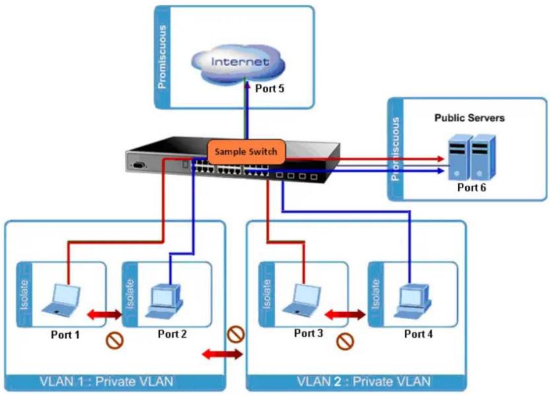
flowchart
graph TD
    subgraph_VLAN1["VIEN 1 : Private VLAN"]
        A["Isolate"] --> B["Port 1"]
        C["Isolate"] --> D["Port 2"]
        E["Isolate"] --> F["Port 3"]
        G["Isolate"] --> H["Port 4"]
        I["Internet"] --> J["Port 5"]
    end

    subgraph_VLAN2["VIEN 2 : Private VLAN"]
        K["Isolate"] --> L["Port 3"]
        M["Isolate"] --> N["Port 4"]
        O["Isolate"] --> P["Port 6"]
        Q["Public Servers"] --> R["Port 6"]
    end

    A --> J
    K --> L
    M --> N
    O --> P
    style A fill:#f9f,stroke:#333
    style B fill:#ccf,stroke:#333
    style C fill:#ccf,stroke:#333
    style D fill:#ccf,stroke:#333
    style E fill:#ccf,stroke:#333
    style F fill:#ccf,stroke:#333
    style G fill:#ccf,stroke:#333
    style H fill:#ccf,stroke:#333
    style I fill:#ccf,stroke:#333
    style J fill:#ccf,stroke:#333
    style K fill:#ccf,stroke:#333
    style L fill:#ccf,stroke:#333
    style M fill:#ccf,stroke:#333
    style N fill:#ccf,stroke:#333
    style O fill:#ccf,stroke:#333
    style P fill:#ccf,stroke:#333
    style Q fill:#ccf,stroke:#333
Setup steps
1. Assign Port Mode
Set Port-1\~Port-4 in Isolate port.
Set Port5 and Port-6 in Promiscuous port. The screen in Figure 4-3-3-15 appears.
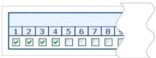
Figure 4-3-3-15: The Configuration of Isolated and Promiscuous Port
4.3.3.9 MAC-based VLAN
The MAC-based VLAN entries can be configured here. This page allows for adding and deleting MAC-based VLAN entries and assigning the entries to different ports. This page shows only static entries. The MAC-based VLAN screen in Figure 4-3-3-16 appears.
MAC-based VLAN Membership Configuration
| Port Members | ||||||||||||
| Delete | MAC Address | VLAN ID | 1 | 2 | 3 | 4 | 5 | 6 | 7 | 8 | 9 | 10 |
| Currently no entries present | ||||||||||||
Add New Entry
Apply Reset
Figure 4-3-3-16: MAC-based VLAN Membership Configuration Page Screenshot
The page includes the following fields:
| Object Description | |
| Delete | To delete a MAC-based VLAN entry, check this box and press save. |
| MAC Address | Indicates the MAC address. |
| VLAN ID | Indicates the VLAN ID. |
| Port Members | A row of check boxes for each port is displayed for each MAC-based VLAN entry. To include a port in a MAC-based VLAN, check the box. To remove or exclude the port from the MAC-based VLAN, make sure the box is unchecked. By default, no ports are members, and all boxes are unchecked. |
| Adding a New MAC-based VLAN | Click “Add New Entry” to add a new MAC-based VLAN entry. An empty row is added to the table, and the MAC-based VLAN entry can be configured as needed. Any unicast MAC address can be configured for the MAC-based VLAN entry. No broadcast or multicast MAC addresses are allowed. Legal values for a VLAN ID are 1 through 4095.The MAC-based VLAN entry is enabled when you click on "Save". A MAC-based VLAN without any port members will be deleted when you click "Save".The “Delete” button can be used to undo the addition of new MAC-based VLANs. |
Buttons
Add New Entry
Click to add a new MAC-based VLAN entry.
Apply
: Click to apply changes
Reset
: Click to undo any changes made locally and revert to previously saved values.
4.3.3.10 IP Subnet-based VLAN Membership Configuration
The IP subnet to VLAN ID mappings can be configured here. This page allows adding, updating and deleting IP subnet to VLAN ID mapping entries and assigning them to different ports. The MAC-based VLAN screen in Figure 4-3-3-17 appears.
Auto-refresh □ Refresh
IP Subnet-based VLAN Membership Configuration
| Port Members | |||||||||||||
| Delete | IP Address | Mask Length | VLAN ID | 1 | 2 | 3 | 4 | 5 | 6 | 7 | 8 | 9 | 10 |
| Currently no entries present | |||||||||||||
Add New Entry
Apply Reset
Figure 4-3-3-17: IP Subnet-based VLAN Membership Configuration page screenshot
The page includes the following fields:
| Object Description | |
| Delete | To delete a MAC-based VLAN entry, check this box and press save. |
| IP Address | Indicates the subnet's IP address (Any of the subnet's host addresses can be also provided here, the application will convert it automatically). |
| Mask Length | Indicates the subnet's mask length. |
| VLAN ID | Indicates the VLAN ID the subnet will be mapped to. IP Subnet to VLAN ID is a unique matching. |
| Port Members | A row of check boxes for each port is displayed for each IP subnet to VLAN ID mapping entry. To include a port in a mapping, simply check the box. To remove or exclude the port from the mapping, make sure the box is unchecked. By default, no ports are members and all boxes are unchecked. |
| Adding a New IP subnet-based VLAN | Click to add a new IP subnet to VLAN ID mapping entry. An empty row is added to the table, and the mapping can be configured as needed. Any IP address/mask can be configured for the mapping. Legal values for the VLAN ID are 1 to 4095.The IP subnet to VLAN ID mapping entry is enabled when you click on "Apply". The delete button can be used to undo the addition of new mappings. The maximum possible IP subnet to VLAN ID mappings are limited to 128 |
Buttons
Add New Entry
Click to add a new IP Subnet based VLAN entry.
Apply
: Click to apply changes
Reset
Click to undo any changes made locally and revert to previously saved values.
Auto-refresh ☐: Check this box to refresh the page automatically. Automatic refresh occurs every 3 seconds.
Refresh
Click to refresh the page immediately.
4.3.3.11 Protocol-based VLAN
This page allows you to add new protocols to Group Name (unique for each Group) mapping entries as well as allow you to see and delete already mapped entries for the switch. The Protocol-based VLAN screen in Figure 4-3-3-18 appears.
Protocol to Group Mapping Table
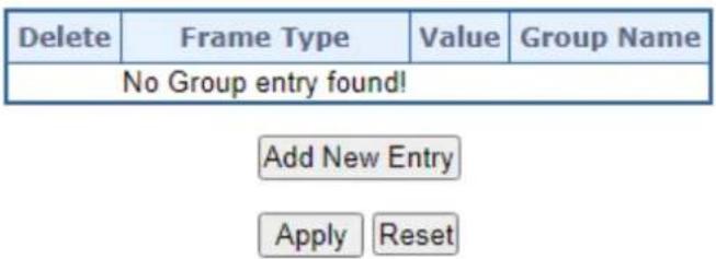
Figure 4-3-3-18: Protocol to Group Mapping Table Page Screenshot
The page includes the following fields:
| Object Description | |
| Delete | To delete a Protocol to Group Name map entry, check this box. The entry will be deleted on the switch during the next Save. |
| Frame Type | Frame Type can have one of the following values:1. Ethernet2. LLC3. SNAPNote: On changing the Frame type field, valid value of the following text field will vary depending on the new frame type you selected. |
| Value | Valid value that can be entered in this text field depends on the option selected from the preceding Frame Type selection menu.Below is the criteria for three different Frame Types:1. For Ethernet: Values in the text field when Ethernet is selected as a Frame Type is called etype. Valid values for etype ranges from 0x0600-0xffff2. For LLC: Valid value in this case is comprised of two different sub-values.a. DSAP: 1-byte long string (0x00-0xff)b. SSAP: 1-byte long string (0x00-0xff)3. For SNAP: Valid value in this case also is comprised of two different sub-values.a. OUI: OUI (Organizationally Unique Identifier) is value in format of xx-xx-xx where each pair (xx) in string is a hexadecimal value ranges from 0x00-0xff.b. PID: If the OUI is hexadecimal 000000, the protocol ID is the Ethernet type (EtherType) field value for the protocol running on top of SNAP; if the OUI is an OUI for a particular organization, the protocol ID is a value assigned by that organization to the protocol running on top of SNAP.In other words, if value of OUI field is 00-00-00 then value of PID will be etype (0x0600-0xffff) and if value of OUI is other than 00-00-00 then valid value of PID will be any value from 0x0000 to 0xffff. |
| • Group Name | A valid Group Name is a unique 16-character long string for every entry which consists of a combination of alphabets (a-z or A-Z) and integers(0-9).Note: special character and underscore(_) are not allowed. |
| • Adding a New Group to VLAN mapping entry | Click “Add New Entry” to add a new entry in mapping table. An empty row is added to the table; Frame Type, Value and the Group Name can be configured as needed.The “Delete” button can be used to undo the addition of new entry. |
Buttons
Add New Entry
Click to add a new entry in mapping table.
Apply
: Click to apply changes
Reset
: Click to undo any changes made locally and revert to previously saved values.
4.3.3.12 Protocol-based VLAN Membership
This page allows you to map a already configured Group Name to a VLAN for the switch. The Group Name to VLAN Mapping Table screen in Figure 4-3-3-19 appears.
Group Name to VLAN Mapping Table
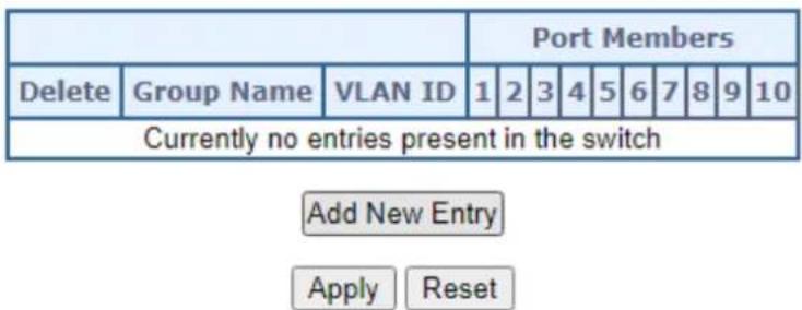
Figure 4-3-3-19: Group Name to VLAN Mapping Table Page Screenshot
The page includes the following fields:
| Object Description | |
| Delete | To delete a Group Name to VLAN map entry, check this box. The entry will be deleted on the switch during the next Save |
| Group Name | A valid Group Name is a string of almost 16 characters which consists of acombination of alphabets (a-z or A-Z) and integers(0-9), no special character is allowed. Whichever Group name you try map to a VLAN must be present in Protocol to Group mapping table and must not be preused by any other existing mapping entry on this page. |
| • VLAN ID | Indicates the ID to which Group Name will be mapped. A valid VLAN ID ranges from 1-4095. |
| • Port Members | A row of check boxes for each port is displayed for each Group Name to VLAN ID mapping. To include a port in a mapping, check the box. To remove or exclude the port from the mapping, make sure the box is unchecked. By default, no ports are members, and all boxes are unchecked. |
| • Adding a New Group to VLAN mapping entry | Click “Add New Entry” to add a new entry in mapping table. An empty row is added to the table, the Group Name, VLAN ID and port members can be configured as needed. Legal values for a VLAN ID are 1 through 4095. The “Delete” button can be used to undo the addition of new entry. |
Buttons
Add New Entry
Click to add a new entry in mapping table.
Apply
: Click to apply changes
Reset
Click to undo any changes made locally and revert to previously saved values.
4.3.2.13 VLAN Translation
This page allows you to configure switch Ports to use a given VLAN Translation Mapping Group. This will enable all VLAN Translation mappings of that group (if any) on the selected switch port. The VLAN Translation provide following items for configuration.
■ Port To Group Configuration
Configure Port to VLAN Translation Mapping Group
The Port To Group Configuration screens in Figure 4-3-3-20 appears.
Auto-refresh □ Refresh
VLAN Translation Port Configuration
| Port | Group Configuration | |
| Default | Group ID | |
| * | ✓ | |
| 1 | 1 ✓ | |
| 2 | 2 ✓ | |
| 3 | 3 ✓ | |
| 4 | 4 ✓ | |
| 5 | 5 ✓ | |
| 6 | 6 ✓ | |
| 7 | 7 ✓ | |
| 8 | 8 ✓ | |
| 9 | 9 ✓ | |
| 10 | 10 ✓ | |

Figure 4-3-2-20 : Port To Group Configuration Page Screenshot
The page includes the following fields:
| Object Description | |
| • Port | The Port column shows the list of ports for which you can configure the VLAN Translation Mapping Group. |
| Group Configuration | |
| • Default | To set the switch port to use the default VLAN Translation Group click the checkbox and press Save. |
| • Group ID | The VLAN Translation mappings are organized into Groups, identified by the Group ID. This way a port is configured to use a number of VLAN Translation mappings easily by simply configuring it to use a given group. Then number of possible groups in a switch is equal to the number of ports present in this switch. A port can be configured to use any of the groups, but only one at any given time.Multiple ports can be configured to use the same group. A valid Group ID is an integer value from 1 to 10.Note: By default, each port is set to use the group with Group ID equal to the port number. For example, port #1 is by default set to use group with GID = 1. |
Buttons
Auto-refresh ☐: Check this box to refresh the page automatically. Automatic refresh occurs every 3 seconds.

Click to refresh the page immediately.

: Click to apply changes

Click to undo any changes made locally and revert to previously saved values.
The VLAN Translation Mappings Configuration screens in Figure 4-3-3-21 & Figure 4-3-3-22 appears.
Auto-refresh □ Refresh Remove All
VLAN Translation Mapping Table
| Group ID | Direction | VID | TVID | |
| 1 | Both | 1 | 2 | e x + |
Figure 4-3-2-21 : LAN Translation Mappings Configuration Page Screenshot
The page includes the following fields:
| Object Description | |
| • Group | The VLAN Translation mappings are organized into Groups, identified by the Group ID. This way a port is configured to use a number of VLAN Translation mappings easily by simply configuring it to use a given group. Then number of possible groups in a switch is equal to the number of ports present in this switch. A port can be configured to use any of the groups, but only one at any given time. Multiple ports can be configured to use the same group. A valid Group ID is an integer value from 1 to 10.Note: By default, each port is set to use the group with Group ID equal to the port number. For example, port #1 is by default set to use group with GID = 1. |
| • Direction | Indicates the direction of the VLAN Translation and it refers to the switch. The direction can be 'Ingress', where the translation takes place on the VLAN ID of frames entering the switch port, 'Egress', where the translation takes place on the VLAN ID of frames exiting the switch port, or 'Both', where the translation takes place on both of the above directions. |
| • VID | Indicates the VLAN ID of the mapping (i.e. 'source' VLAN). A valid VLAN ID ranges from 1 to 4095. |
• TVID | Indicates the translated VLAN ID to which a VLAN ID of a frame will be translated to. A valid translated VLAN ID ranges from 1 to 4095.You can modify each VLAN Translation mapping in the table using the following buttons:Edit: Edits the mapping row.XDelete: Deletes the mapping.Add: Adds a new mapping. |
Press ⭕ button to adds a new mapping and the screen is following appears.

Figure 4-3-2-22 : LAN Translation Mappings Configuration Page Screenshot
The page includes the following fields:
| Object Description | |
| • Group ID | The VLAN Translation mappings are organized into Groups, identified by the Group ID. This way a port is configured to use a number of VLAN Translation mappings easily by simply configuring it to use a given group. Then number of possible groups in a switch is equal to the number of ports present in this switch. A port can be configured to use any of the groups, but only one at any given time. Multiple ports can be configured to use the same group. A valid Group ID is an integer value from 1 to 10.Note: By default, each port is set to use the group with Group ID equal to the port number. For example, port #1 is by default set to use group with GID = 1. |
| • DIR | Indicates the direction of the VLAN Translation and it refers to the switch. The direction can be 'Ingress', where the translation takes place on the VLAN ID of frames entering the switch port, 'Egress', where the translation takes place on the VLAN ID of frames exiting the switch port, or 'Both', where the translation takes place on both of the above directions. |
| • VID | Indicates the VLAN ID of the mapping (i.e. 'source' VLAN). A valid VLAN ID ranges from 1 to 4095. |
| • TVID | Indicates the translated VLAN ID to which a VLAN ID of a frame will be translated to. A valid translated VLAN ID ranges from 1 to 4095. |
Buttons
Save
Click to apply changes
Reset
Click to undo any changes made locally and revert to previously saved values.
Cancel
: Return to the previous page; any changes made locally will be undone..
4.3.4 Spanning Tree Protocol
4.3.4.1 Theory
The Spanning Tree protocol can be used to detect and disable network loops, and to provide backup links between switches, bridges or routers. This allows the switch to interact with other bridging devices in your network to ensure that only one route exists between any two stations on the network, and provide backup links which automatically take over when a primary link goes down. The spanning tree algorithms supported by this switch include these versions:
■ STP – Spanning Tree Protocol (IEEE 802.1D)
■ RSTP – Rapid Spanning Tree Protocol (IEEE 802.1w)
■ MSTP – Multiple Spanning Tree Protocol (IEEE 802.1s)
The IEEE 802.1D Spanning Tree Protocol and IEEE 802.1w Rapid Spanning Tree Protocol allow for the blocking of links between switches that form loops within the network. When multiple links between switches are detected, a primary link is established. Duplicated links are blocked from use and become standby links. The protocol allows for the duplicate links to be used in the event of a failure of the primary link. Once the Spanning Tree Protocol is configured and enabled, primary links are established and duplicated links are blocked automatically. The reactivation of the blocked links (at the time of a primary link failure) is also accomplished automatically without operator intervention.
This automatic network reconfiguration provides maximum uptime to network users. However, the concepts of the Spanning Tree Algorithm and protocol are a complicated and complex subject and must be fully researched and understood. It is possible to cause serious degradation of the performance of the network if the Spanning Tree is incorrectly configured. Please read the following before making any changes from the default values.
The Switch STP performs the following functions:
■ Creates a single spanning tree from any combination of switching or bridging elements.
- Creates multiple spanning trees – from any combination of ports contained within a single switch, in user specified groups.
■ Automatically reconfigures the spanning tree to compensate for the failure, addition, or removal of any element in the tree.
■ Reconfigures the spanning tree without operator intervention.
Bridge Protocol Data Units
For STP to arrive at a stable network topology, the following information is used:
■ The unique switch identifier
■ The path cost to the root associated with each switch port
■ The port identifier
STP communicates between switches on the network using Bridge Protocol Data Units (BPDUs). Each BPDU contains the following information:
■ The unique identifier of the switch that the transmitting switch currently believes is the root switch
■ The path cost to the root from the transmitting port
■ The port identifier of the transmitting port
The switch sends BPDUs to communicate and construct the spanning-tree topology. All switches connected to the LAN on which the packet is transmitted will receive the BPDU. BPDUs are not directly forwarded by the switch, but the receiving switch uses the information in the frame to calculate a BPDU, and, if the topology changes, initiates a BPDU transmission.
The communication between switches via BPDUs results in the following:
■ One switch is elected as the root switch
■ The shortest distance to the root switch is calculated for each switch
A designated switch is selected. This is the switch closest to the root switch through which packets will be forwarded to the root.
A port for each switch is selected. This is the port providing the best path from the switch to the root switch.
■ Ports included in the STP are selected.
Creating a Stable STP Topology
It is to make the root port a fastest link. If all switches have STP enabled with default settings, the switch with the lowest MAC address in the network will become the root switch. By increasing the priority (lowering the priority number) of the best switch, STP can be forced to select the best switch as the root switch.
When STP is enabled using the default parameters, the path between source and destination stations in a switched network might not be ideal. For instance, connecting higher-speed links to a port that has a higher number than the current root port can cause a root-port change.
STP Port States
The BPDUs take some time to pass through a network. This propagation delay can result in topology changes where a port that transitioned directly from a Blocking state to a Forwarding state could create temporary data loops. Ports must wait for new network topology information to propagate throughout the network before starting to forward packets. They must also wait for the packet lifetime to expire for BPDU packets that were forwarded based on the old topology. The forward delay timer is used to allow the network topology to stabilize after a topology change. In addition, STP specifies a series of states a port must transition through to further ensure that a stable network topology is created after a topology change.
Each port on a switch using STP exists is in one of the following five states:
■ Blocking – the port is blocked from forwarding or receiving packets
■ Listening – the port is waiting to receive BPDU packets that may tell the port to go back to the blocking state
■ Learning – the port is adding addresses to its forwarding database, but not yet forwarding packets
■ Forwarding – the port is forwarding packets
■ Disabled – the port only responds to network management messages and must return to the blocking state first
A port transitions from one state to another as follows:
■ From initialization (switch boot) to blocking
■ From blocking to listening or to disabled
■ From listening to learning or to disabled
■ From learning to forwarding or to disabled
■ From forwarding to disabled
■ From disabled to blocking
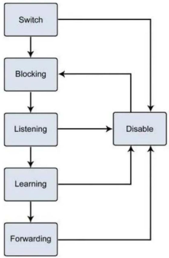
flowchart
graph TD
    A["Switch"] --> B["Blocking"]
    B --> C["Listening"]
    C --> D["Learning"]
    D --> E["Forwarding"]
    E --> F["Disable"]
    F --> B
    C --> G["Disable"]
    G --> F
Figure 4-3-4-1: STP Port State Transitions
You can modify each port state by using management software. When you enable STP, every port on every switch in the network goes through the blocking state and then transitions through the states of listening and learning at power up. If properly configured, each port stabilizes to the forwarding or blocking state. No packets (except BPDUs) are forwarded from, or received by, STP enabled ports until the forwarding state is enabled for that port.
2. STP Parameters
STP Operation Levels
The Switch allows for two levels of operation: the switch level and the port level. The switch level forms a spanning tree consisting of links between one or more switches. The port level constructs a spanning tree consisting of groups of one or more ports. The STP operates in much the same way for both levels.

On the switch level, STP calculates the Bridge Identifier for each switch and then sets the Root Bridge and the Designated Bridges.
On the port level, STP sets the Root Port and the Designated Ports.
The following are the user-configurable STP parameters for the switch level:
| Parameter | Description | Default Value |
| Bridge Identifier(Not user configurable except by setting priority below) | A combination of the User-set priority and the switch's MAC address.The Bridge Identifier consists of two parts: a 16-bit priority and a 48-bit Ethernet MAC address 32768 + MAC | 32768 + MAC |
| Priority | A relative priority for each switch – lower numbers give a higher priority and a greater chance of a given switch being elected as the root bridge | 32768 |
| Hello Time The length of time between broadcasts of the hello message by the switch | 2 seconds | |
| Maximum Age Timer | Measures the age of a received BPDU for a port and ensures that the BPDU is discarded when its age exceeds the value of the maximum age timer. | 20 seconds |
| Forward Delay Timer | The amount time spent by a port in the learning and listening states waiting for a BPDU that may return the port to the blocking state. | 15 seconds |
The following are the user-configurable STP parameters for the port or port group level:
| Variable | Description | Default Value |
| Port Priority | A relative priority for each port –lower numbers give a higher priority and a greater chance of a given port being elected as the root port | 128 |
| Port Cost | A value used by STP to evaluate paths – STP calculates path costs and selects the path with the minimum cost as the active path | 200,000-100Mbps Fast Ethernet ports20,000-1000Mbps Gigabit Ethernet ports0 - Auto |
Default Spanning-Tree Configuration
| Feature Default Value | |
| Enable state | STP disabled for all ports |
| Port priority 128 | |
| Port cost 0 | |
| Bridge Priority 32,768 |
User-Changeable STA Parameters
The Switch's factory default setting should cover the majority of installations. However, it is advisable to keep the default settings as set at the factory; unless, it is absolutely necessary. The user changeable parameters in the Switch are as follows:
Priority – A Priority for the switch can be set from 0 to 65535. 0 is equal to the highest Priority.
Hello Time – The Hello Time can be from 1 to 10 seconds. This is the interval between two transmissions of BPDU packets sent by the Root Bridge to tell all other Switches that it is indeed the Root Bridge. If you set a Hello Time for your Switch, and it is not the Root Bridge, the set Hello Time will be used if and when your Switch becomes the Root Bridge.

The Hello Time cannot be longer than the Max. Age; otherwise, a configuration error will occur.
Max. Age – The Max Age can be from 6 to 40 seconds. At the end of the Max Age, if a BPDU has still not been received from the Root Bridge, your Switch will start sending its own BPDU to all other Switches for permission to become the Root Bridge. If it turns out that your Switch has the lowest Bridge Identifier, it will become the Root Bridge.
Forward Delay Timer – The Forward Delay can be from 4 to 30 seconds. This is the time any port on the
Switch spends in the listening state while moving from the blocking state to the forwarding state.

Observe the following formulas when setting the above parameters:
Max. Age _ 2 x (Forward Delay - 1 second)
Max. Age _ 2 x (Hello Time + 1 second)
Port Priority – A Port Priority can be from 0 to 240. The lower the number, the greater the probability the port will be chosen as the Root Port.
Port Cost – A Port Cost can be set from 0 to 200000000. The lower the number, the greater the probability the port will be chosen to forward packets.
3. Illustration of STP
A simple illustration of three switches connected in a loop is depicted in the below diagram. In this example, you can anticipate some major network problems if the STP assistance is not applied.
If switch A broadcasts a packet to switch B, switch B will broadcast it to switch C, and switch C will broadcast it to back to switch A and so on. The broadcast packet will be passed indefinitely in a loop, potentially causing a network failure. In this example, STP breaks the loop by blocking the connection between switch B and C. The decision to block a particular connection is based on the STP calculation of the most current Bridge and Port settings.
Now, if switch A broadcasts a packet to switch C, then switch C will drop the packet at port 2 and the broadcast will end there. Setting-up STP using values other than the defaults, can be complex. Therefore, you are advised to keep the default factory settings and STP will automatically assign root bridges/ports and block loop connections. Influencing STP to choose a particular switch as the root bridge using the Priority setting, or influencing STP to choose a particular port to block using the Port Priority and Port Cost settings is, however, relatively straight forward.
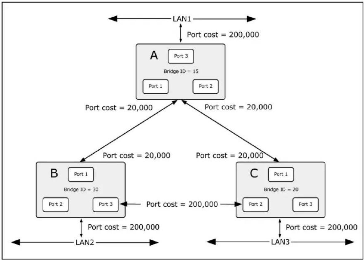
flowchart
graph TD
    A["Bridge ID = 15"] -->|Port cost = 20,000| B["B"]
    A -->|Port cost = 20,000| C["C"]
    B -->|Port cost = 20,000| A
    B -->|Port cost = 20,000| C
    C -->|Port cost = 20,000| A
    C -->|Port cost = 20,000| B
    B -->|Port cost = 200,000| A
    B -->|Port cost = 200,000| C
    A -->|LAN1| A
    C -->|LAN3| C
    style A fill:#f9f,stroke:#333
    style B fill:#ccf,stroke:#333
    style C fill:#ccf,stroke:#333
Figure 4-3-4-2: Before Applying the STA Rules
In this example, only the default STP values are used.
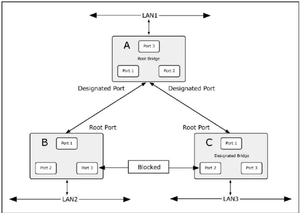
flowchart
graph TD
    A["Root Bridge"] -->|LAN1| A
    A -->|Designated Port| B["Node B"]
    A -->|Designated Port| C["Node C"]
    B -->|LAN2| B
    B -->|LAN2| B
    C -->|LAN3| C
    C -->|LAN3| C
    B -->|Port 1| B
    B -->|Port 2| B
    B -->|Port 3| B
    C -->|Port 1| C
    C -->|Port 2| C
    C -->|Port 3| C
    B -->|Blocked| C
    style A fill:#ccc,stroke:#333
    style B fill:#ccc,stroke:#333
    style C fill:#ccc,stroke:#333
Figure 4-3-4-3: After Applying the STA Rules
The switch with the lowest Bridge ID (switch C) was elected the root bridge, and the ports were selected to give a high port cost between switches B and C. The two (optional) Gigabit ports (default port cost = 20,000) on switch A are connected to one (optional) Gigabit port on both switch B and C. The redundant link between switch B and C is deliberately chosen as a 100 Mbps Fast Ethernet link (default port cost = 200,000). Gigabit ports could be used, but the port cost should be increased from the default to ensure that the link between switch B and switch C is the blocked link.
4.3.4.2 STP System Configuration
This page allows you to configure STP system settings. The settings are used by all STP Bridge instances in the Switch. The Managed Metro Switch support the following Spanning Tree protocols:
- Compatible -- Spanning Tree Protocol (STP): Provides a single path between end stations, avoiding and eliminating loops.
- Normal -- Rapid Spanning Tree Protocol (RSTP) : Detects and uses of network topologies that provide faster spanning tree convergence, without creating forwarding loops.
- Extension – Multiple Spanning Tree Protocol (MSTP) : Defines an extension to RSTP to further develop the usefulness of virtual LANs (VLANs). This "Per-VLAN" Multiple Spanning Tree Protocol configures a separate Spanning Tree for each VLAN group and blocks all but one of the possible alternate paths within each Spanning Tree.
The STP System Configuration screen in Figure 4-3-4-4 appears.
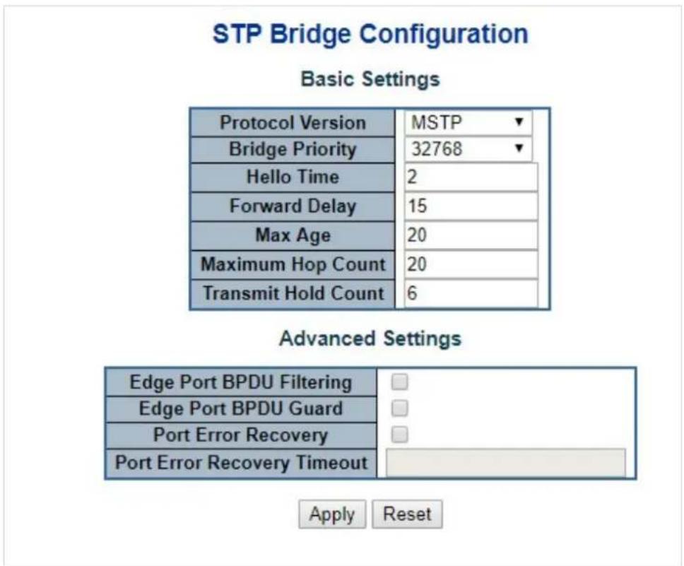
Figure 4-3-4-4: STP Bridge Configuration Page Screenshot
The page includes the following fields:
Basic Settings
| Object Description | |
| Protocol Version | The STP protocol version setting. Valid values are:STP (IEEE 802.1D Spanning Tree Protocol)RSTP (IEEE 802.2w Rapid Spanning Tree Protocol)MSTP (IEEE 802.1s Multiple Spanning Tree Protocol) |
| Bridge Priority | Controls the bridge priority. Lower numeric values have better priority. The bridge priority plus the MSTI instance number, concatenated with the 6-byte MAC address of the switch forms a Bridge Identifier.For MSTP operation, this is the priority of the CIST. Otherwise, this is the priority of the STP/RSTP bridge. |
| Hello Time | The interval between sending STP BPDU's. Valid values are in the range 1 to 10 seconds, default is 2 seconds |
| Forward Delay | The delay used by STP Bridges to transition Root and Designated Ports to Forwarding (used in STP compatible mode). Valid values are in the range 4 to 30 seconds-Default: 15-Minimum: The higher of 4 or [(Max. Message Age / 2) + 1]-Maximum: 30 |
| Max Age | The maximum age of the information transmitted by the Bridge when it is the Root Bridge. Valid values are in the range 6 to 40 seconds.-Default: 20-Minimum: The higher of 6 or [2 x (Hello Time + 1)].-Maximum: The lower of 40 or [2 x (Forward Delay -1)] |
| Maximum Hop Count | This defines the initial value of remaining Hops for MSTI information generated at the boundary of an MSTI region. It defines how many bridges a root bridge can distribute its BPDU information. Valid values are in the range 6 to 40 hops. |
| Transmit Hold Count | The number of BPDU's a bridge port can send per second. When exceeded, transmission of the next BPDU will be delayed. Valid values are in the range 1 to 10 BPDU's per second. |
Advanced Settings
| Object Description | |
| • Edge Port BPDU Filtering | Control whether a port explicitly configured as Edge will transmit and receive BPDUs. |
| • Edge Port BPDU Guard | Control whether a port explicitly configured as Edge will disable itself upon reception of a BPDU. The port will enter the error-disabled state, and will be removed from the active topology. |
| • Port Error Recovery | Control whether a port in the error-disabled state automatically will be enabled after a certain time. If recovery is not enabled, ports have to be disabled and re-enabled for normal STP operation. The condition is also cleared by a system reboot. |
| • Port Error RecoveryTimeout | The time that has to pass before a port in the error-disabled state can be enabled. Valid values are between 30 and 86400 seconds (24 hours). |

The Managed Metro Switch implements the Rapid Spanning Protocol as the default spanning tree protocol. When selecting “Compatibles” mode, the system uses the RSTP (802.1w) to be compatible and to co-work with another STP (802.1D)'s BPDU control packet.
Buttons
Apply
: Click to apply changes
Reset
: Click to undo any changes made locally and revert to previously saved values.
4.3.4.3 Bridge Status
This page provides a status overview for all STP bridge instances. The displayed table contains a row for each STP bridge instance, where the column displays the following information: The Bridge Status screen in Figure 4-3-4-5 appears.
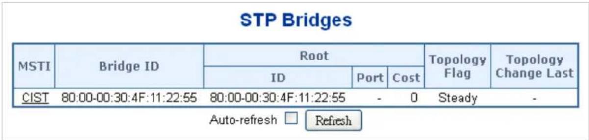
Figure 4-3-4-5: STP Bridge Status Page Screenshot
The page includes the following fields:
| Object Description | |
| • MSTI | The Bridge Instance. This is also a link to the STP Detailed Bridge Status. |
| • Bridge ID | The Bridge ID of this Bridge instance. |
| • Root ID | The Bridge ID of the currently elected root bridge. |
| • Root Port | The switch port currently assigned the root port role. |
| • Root Cost | Root Path Cost. For the Root Bridge this is zero. For all other Bridges, it is the sum of the Port Path Costs on the least cost path to the Root Bridge. |
| • Topology Flag | The current state of the Topology Change Flag for this Bridge instance. |
| • Topology Change Last | The time since last Topology Change occurred. |
Buttons
Auto-refresh ☐: Check this box to refresh the page automatically. Automatic refresh occurs every 3 seconds.
Refresh: Click to refresh the page immediately.
4.3.4.4 CIST Port Configuration
This page allows the user to inspect the current STP CIST port configurations, and possibly change them as well. The CIST Port Configuration screen in Figure 4-3-4-6 appears.
STP CIST Port Configuration
CIST Aggregated Port Configuration
| Port | STP Enabled | Path Cost | Priority | Admin Edge | Auto Edge | Restricted | BPDU Guard | Point-to- Point | |||
| Role | TCN | ||||||||||
| - | □ | Auto | √ | 128 | Non-Edge | √ | □ | □ | □ | Forced True | |
CIST Normal Port Configuration
| Port | STP Enabled | Path Cost | Priority | Admin Edge | Auto Edge | Restricted | BPDU Guard | Point-to- Point | |||
| Role | TCN | ||||||||||
| * | |||||||||||
| 1 | Auto | 128 | ✓ | Auto | |||||||
| 2 | Auto | 128 | ✓ | Auto | |||||||
| 3 | Auto | 128 | ✓ | Auto | |||||||
| 4 | Auto | 128 | ✓ | Auto | |||||||
| 5 | Auto | 128 | ✓ | Auto | |||||||
| 6 | Auto | 128 | ✓ | Auto | |||||||
| 7 | Auto | 128 | ✓ | Auto | |||||||
| 8 | Auto | 128 | ✓ | Auto | |||||||
Figure 4-3-4-6 : STP CIST Port Configuration Page Screenshot
The page includes the following fields:
| Object Description | |
| • Port | The switch port number of the logical STP port. |
| • STP Enabled | Controls whether RSTP is enabled on this switch port. |
| • Path Cost | Controls the path cost incurred by the port. TheAutosetting will set the path cost as appropriate by the physical link speed, using the 802.1D recommended values. Using theSpecificsetting, a user-defined value can be entered. The path cost is used when establishing the active topology of the network. Lower path cost ports are chosen as forwarding ports in favor of higher path cost ports. Valid values are in the range 1 to 200000000. |
| • Priority | Controls the port priority. This can be used to control priority of ports having identical port cost. (See above).Default: 128Range: 0-240, in steps of 16 |
| • AdminEdge | Controls whether the operEdge flag should start as being set or cleared. (Theinitial operEdge state when a port is initialized). |
| • AutoEdge | Controls whether the bridge should enable automatic edge detection on the bridge port. This allows operEdge to be derived from whether BPDU's are received on the port or not. |
| • Restricted Role | If enabled, causes the port not to be selected as Root Port for the CIST or any MSTI, even if it has the best spanning tree priority vector. Such a port will be selected as an Alternate Port after the Root Port has been selected. If set, it can cause lack of spanning tree connectivity. It can be set by a network administrator to prevent bridges external to a core region of the network influence the spanning tree active topology, possibly because those bridges are not under the full control of the administrator. This feature is also known as Root Guard. |
| • Restricted TCN | If enabled, causes the port not to propagate received topology change notifications and topology changes to other ports. If set it can cause temporary loss of connectivity after changes in a spanning tree's active topology as a result of persistently incorrect learned station location information. It is set by a network administrator to prevent bridges external to a core region of the network, causing address flushing in that region, possibly because those bridges are not under the full control of the administrator or the physical link state of the attached LANs transits frequently. |
| • BPDU Guard | If enabled, causes the port to disable itself upon receiving valid BPDU's. Contrary to the similar bridge setting, the port Edge status does not effect this setting.A port entering error-disabled state due to this setting is subject to the bridge Port Error Recovery setting as well. |
| • Point-to-point | Controls whether the port connects to a point-to-point LAN rather than a shared medium. This can be automatically determined, or forced either true or false.Transitions to the forwarding state is faster for point-to-point LANs than for shared media. |
Buttons
Apply
: Click to apply changes
Reset
: Click to undo any changes made locally and revert to previously saved values.
By default, the system automatically detects the speed and duplex mode used on each port, and configures the path cost according to the values shown below. Path cost "0" is used to indicate auto-configuration mode. When the short path cost method is selected and the default path cost recommended by the IEEE 8021w standard exceeds 65,535, the default is set to 65,535.
| Port Type | IEEE 802.1D-1998 | IEEE 802.1w-2001 |
| Ethernet | 50-600 | 200,000-20,000,000 |
| Fast Ethernet | 10-60 | 20,000-2,000,000 |
| Gigabit Ethernet | 3-10 | 2,000-200,000 |
Table 4-3-4-1: Recommended STP Path Cost Range
| Port Type | Link Type | IEEE 802.1D-1998 | IEEE 802.1w-2001 |
| Ethernet | Half Duplex | 100 | 2,000,000 |
| Full Duplex | 95 | 1,999,999 | |
| Trunk | 90 | 1,000,000 | |
| Fast Ethernet | Half Duplex | 19 | 200,000 |
| Full Duplex | 18 | 100,000 | |
| Trunk | 15 | 50,000 | |
| Gigabit Ethernet | Full Duplex | 4 | 10,000 |
| Trunk | 3 | 5,000 |
Table 4-3-4-2: Recommended STP Path Costs
| Port Type | Link Type | IEEE 802.1w-2001 |
| Ethernet | Half Duplex | 2,000,000 |
| Full Duplex | 1,000,000 | |
| Trunk | 500,000 | |
| Fast Ethernet | Half Duplex | 200,000 |
| Full Duplex | 100,000 | |
| Trunk | 50,000 | |
| Gigabit Ethernet | Full Duplex | 10,000 |
| Trunk | 5,000 |
Table 4-3-4-3: Default STP Path Costs
4.3.4.5 MSTI Priorities
This page allows the user to inspect the current STP MSTI bridge instance priority configurations, and possibly change them as well. The MSTI Priority screen in Figure 4-3-4-7 appears.
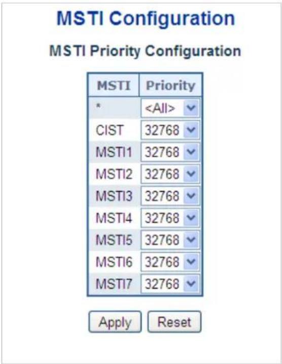
Figure 4-3-4-7: MSTI Priority Page Screenshot
The page includes the following fields:
| Object Description | |
| • MSTI | The bridge instance. The CIST is the default instance, which is always active. |
| • Priority | Controls the bridge priority. Lower numerical values have better priority. The bridge priority plus the MSTI instance number, concatenated with the 6-byte MAC address of the switch forms a Bridge Identifier. |
Buttons
Apply
: Click to apply changes
Reset
: Click to undo any changes made locally and revert to previously saved values.
4.3.4.6 MSTI Configuration
This page allows the user to inspect the current STP MSTI bridge instance priority configurations, and possibly change them as well. The MSTI Configuration screen in Figure 4-3-4-8 appears.
MSTI Configuration
Add VLANs separated by spaces or comma.
Unmapped VLANs are mapped to the CIST. (The default bridge instance).
Configuration Identification
| Configuration Name | 00-30-4f-11-22-33 |
| Configuration Revision | 0 |
MSTI Mapping
| MSTI | VLANs Mapped |
| MSTI1 | |
| MSTI2 | |
| MSTI3 | |
| MSTI4 | |
| MSTI5 | |
| MSTI6 | |
| MSTI7 |


Figure 4-3-4-8: MSTI Configuration Page Screenshot
The page includes the following fields:
Configuration Identification
| Object Description | |
| Configuration Name | The name identifying the VLAN to MSTI mapping. Bridges must share the name and revision (see below), as well as the VLAN-to-MSTI mapping configuration in order to share spanning trees for MSTI's. (Intra-region). The name is at most 32 characters. |
| Configuration Revision | The revision of the MSTI configuration named above. This must be an integer between 0 and 65535. |
MSTI Mapping
| Object Description | |
| • MSTI | The bridge instance. The CIST is not available for explicit mapping, as it will receive the VLANs not explicitly mapped. |
| • VLANs Mapped | The list of VLAN's mapped to the MSTI. The VLANs must be separated with comma and/or space. A VLAN can only be mapped to one MSTI. A unused MSTI should just be left empty. (i.e. not having any VLANs mapped to it.) |
Buttons

: Click to apply changes
Click to undo any changes made locally and revert to previously saved values.
4.3.4.7 MSTI Ports Configuration
This page allows the user to inspect the current STP MSTI port configurations, and possibly change them as well. A MSTI port is a virtual port, which is instantiated separately for each active CIST (physical) port for each MSTI instance configured and applicable for the port. The MSTI instance must be selected before displaying actual MSTI port configuration options.
This page contains MSTI port settings for physical and aggregated ports. The aggregation settings are global. The MSTI Port Configuration screen in Figure 4-3-4-9 & Figure 4-3-4-10 appears.
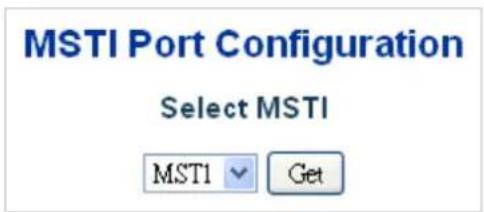
Figure 4-3-4-9 : MSTI Port Configuration Page Screenshot
The page includes the following fields:
MSTI Port Configuration
| Object Description | |
| • Select MSTI | Select the bridge instance and set more detail configuration. |
MST1 MSTI Port Configuration
MSTI Aggregated Ports Configuration
| Port | Path Cost | Priority | ||
| - | Auto | ✓ | 128 ✓ | |
MSTI Normal Ports Configuration
| Port | Path Cost | Priority | |
| * | |||
| 1 | Auto | 128 | |
| 2 | Auto | 128 | |
| 3 | Auto | 128 | |
| 4 | Auto | 128 | |
| 5 | Auto | 128 | |
| 6 | Auto | 128 | |
| 7 | Auto | 128 | |
| 8 | Auto | 128 | |
Figure 4-3-4-10 : MST1 MSTI Port Configuration Page Screenshot
The page includes the following fields:
MSTx MSTI Port Configuration
| Object Description | |
| • Port | The switch port number of the corresponding STP CIST (and MSTI) port. |
| • Path Cost | Controls the path cost incurred by the port. The Auto setting will set the path cost as appropriate by the physical link speed, using the 802.1D recommended values. Using the Specific setting, a user-defined value can be entered. The path cost is used when establishing the active topology of the network. Lower path cost ports are chosen as forwarding ports in favor of higher path cost ports. Valid values are in the range 1 to 200000000. |
| • Priority | Controls the port priority. This can be used to control priority of ports having identical port cost. |
Buttons

Click to set MSTx configuration

: Click to apply changes

: Click to undo any changes made locally and revert to previously saved values.
4.3.4.8 Port Status
This page displays the STP CIST port status for port physical ports in the currently selected switch.
The STP Port Status screen in Figure 4-3-4-11 appears.
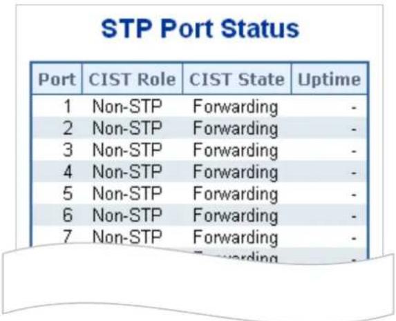
Figure 4-3-4-11: STP Port Status Page Screenshot
The page includes the following fields:
| Object Description | |
| • Port | The switch port number of the logical STP port. |
| • CIST Role | The current STP port role of the ICST port. The port role can be one of the following values:■ AlternatePort■ BackupPort■ RootPort■ DesignatedPort■ Disable |
| • CIST State | The current STP port state of the CIST port . The port state can be one of the following values:■ Disabled■ Learning■ Forwarding |
| • Uptime | The time since the bridge port was last initialized. |
Buttons
Refresh
Click to refresh the page immediately.
Auto-refresh ☐: Check this box to refresh the page automatically. Automatic refresh occurs every 3 seconds
4.3.4.9 Port Statistics
This page displays the STP port statistics counters for port physical ports in the currently selected switch.
The STP Port Statistics screen in Figure 4-3-4-12 appears.
STP Statistics
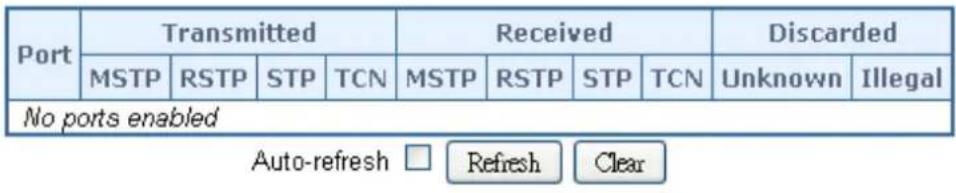
Figure 4-3-4-12: STP Statistics Page Screenshot
The page includes the following fields:
| Object Description | |
| • Port | The switch port number of the logical RSTP port. |
| • MSTP | The number of MSTP Configuration BPDU's received/transmitted on the port. |
| • RSTP | The number of RSTP Configuration BPDU's received/transmitted on the port. |
| • STP | The number of legacy STP Configuration BPDU's received/transmitted on the port. |
| • TCN | The number of (legacy) Topology Change Notification BPDU's received/transmitted on the port. |
| • Discarded Unknown | The number of unknown Spanning Tree BPDU's received (and discarded) on the port. |
| • Discarded Illegal | The number of illegal Spanning Tree BPDU's received (and discarded) on the port. |
Buttons
Auto-refresh ☐: Automatic refresh occurs every 3 seconds.
Refresh
Click to refresh the page immediately.
Clear
: Clears the counters for all ports.
4.3.5 Multicast
4.3.5.1 IGMP Snooping
The Internet Group Management Protocol (IGMP) lets host and routers share information about multicast groups memberships. IGMP snooping is a switch feature that monitors the exchange of IGMP messages and copies them to the CPU for feature processing. The overall purpose of IGMP Snooping is to limit the forwarding of multicast frames to only ports that are a member of the multicast group.
About the Internet Group Management Protocol (IGMP) Snooping
Computers and network devices that want to receive multicast transmissions need to inform nearby routers that they will become members of a multicast group. The Internet Group Management Protocol (IGMP) is used to communicate this information. IGMP is also used to periodically check the multicast group for members that are no longer active. In the case where there is more than one multicast router on a sub network, one router is elected as the 'queried'. This router then keeps track of the membership of the multicast groups that have active members. The information received from IGMP is then used to determine if multicast packets should be forwarded to a given sub network or not. The router can check, using IGMP, to see if there is at least one member of a multicast group on a given subnet work. If there are no members on a sub network, packets will not be forwarded to that sub network.
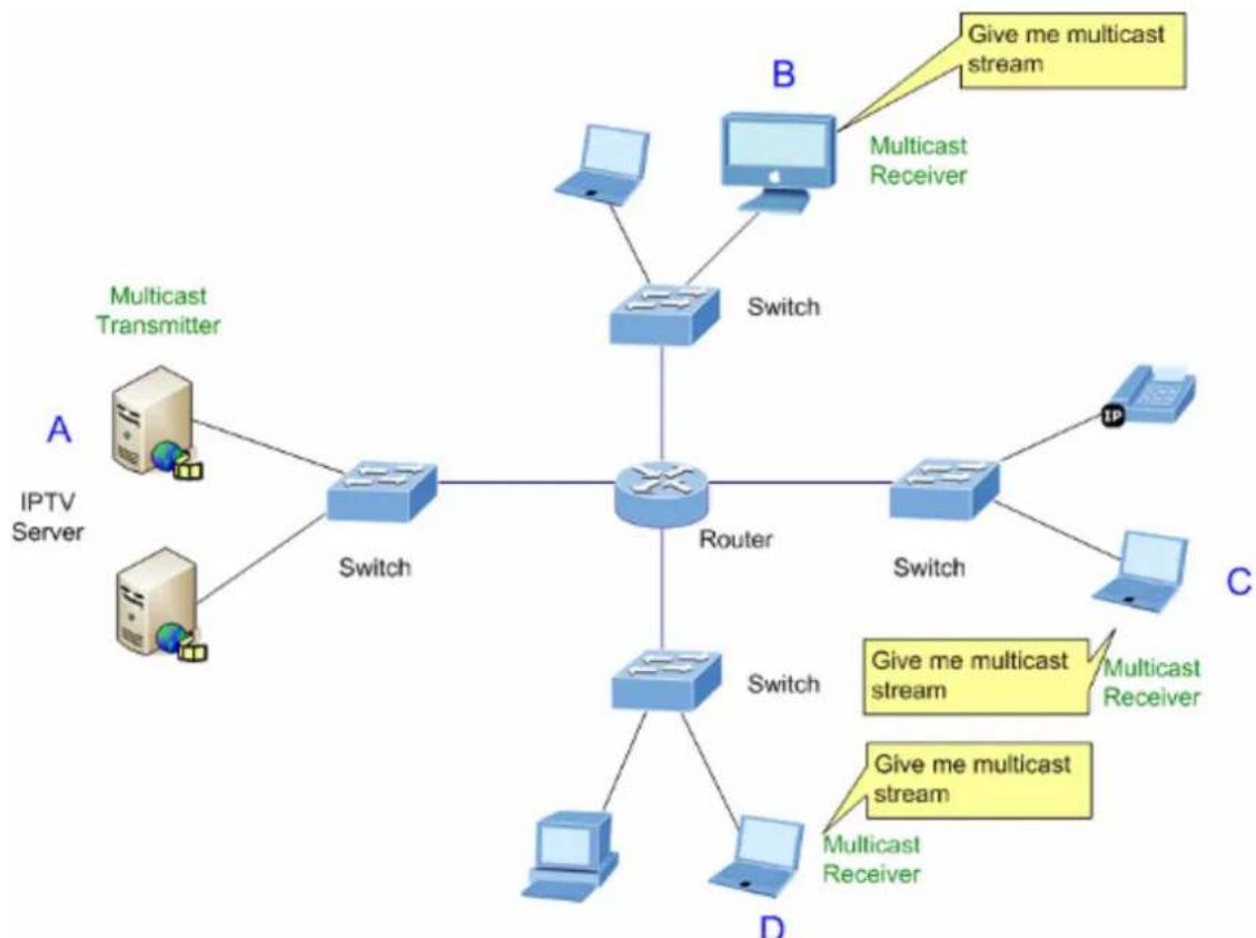
flowchart
graph TD
    A["IPTV Server"] -->|A| Switch1["Switch"]
    A -->|A| Switch2["Switch"]
    A -->|B| B["Multicast Receiver"]
    B -->|B| Switch3["Switch"]
    B -->|C| Switch4["Switch"]
    B -->|D| Switch5["Switch"]
    Switch1 -->|A| Router
    Switch2 -->|A| Router
    Switch3 -->|A| Router
    Switch4 -->|C| Router
    Switch5 -->|D| Router
    Router -->|D| MulticastReceiver["Multicast Receiver"]
    Router -->|B| MulticastReceiver["B"]
    style Router fill:#f9f9f9,stroke:#333
    note right of Router "Give me multicast stream"
Figure 4-3-5-1: Multicast Service
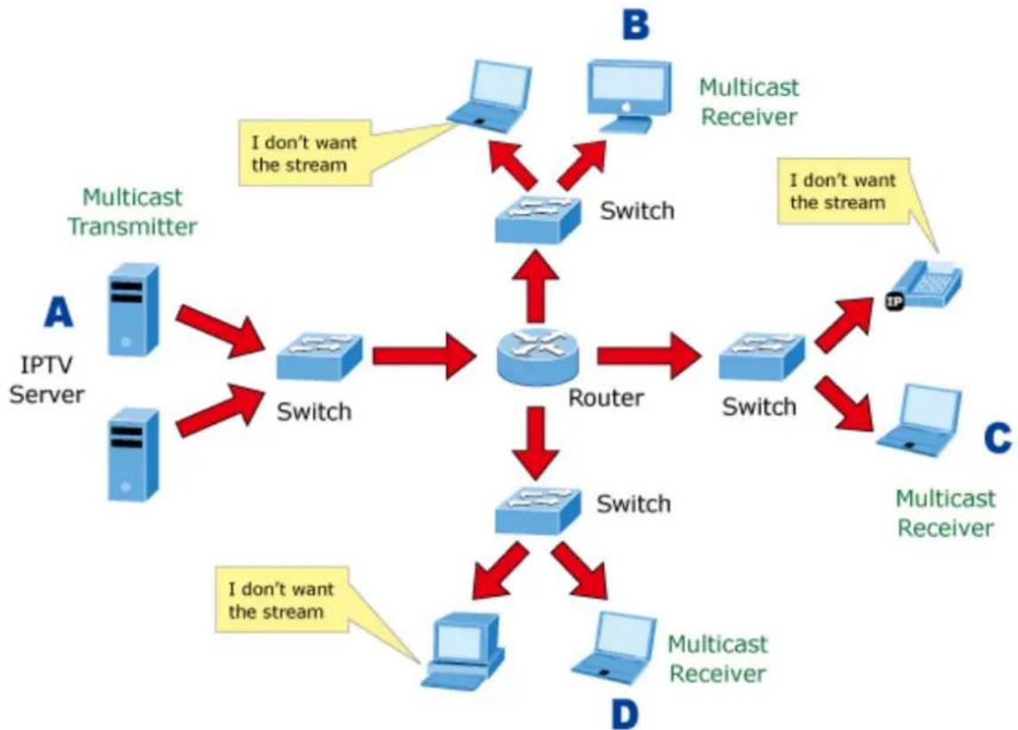
flowchart
graph TD
    A["IPTV Server"] -->|I don't want the stream| B["Switch"]
    A -->|I don't want the stream| C["Router"]
    D["Multicast Transmitter"] -->|I don't want the stream| B
    D -->|I don't want the stream| C
    E["Multicast Receiver"] -->|I don't want the stream| B
    F["Multicast Receiver"] -->|I don't want the stream| C
    G["Multicast Receiver"] -->|I don't want the stream| C
    H["Multicast Receiver"] -->|I don't want the stream| C
    I["Switch"] --> B
    I --> C
    J["Switch"] --> B
    J --> C
    K["Switch"] --> B
    K --> C
    L["Switch"] --> B
    L --> C
Figure 4-3-5-2: Multicast Flooding
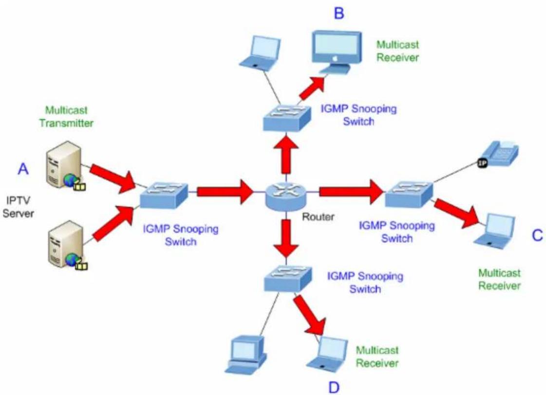
flowchart
graph TD
    A["IPTV Server"] -->|Multicast Transmitter| B["IGMP Snooping Switch"]
    A -->|Multicast Transmitter| C["IGMP Snooping Switch"]
    A -->|Multicast Transmitter| D["IGMP Snooping Switch"]
    B --> E["Router"]
    C --> E
    D --> E
    E --> F["Multicast Receiver"]
    E --> G["Multicast Receiver"]
    E --> H["Multicast Receiver"]
    E --> I["Multicast Receiver"]
    B --> J["IGMP Snooping Switch"]
    C --> J
    D --> J
    J --> K["IP"]
    style A fill:#f9f,stroke:#333
    style B fill:#ccf,stroke:#333
    style C fill:#ccf,stroke:#333
    style D fill:#ccf,stroke:#333
    style E fill:#cfc,stroke:#333
    style F fill:#fcc,stroke:#333
    style G fill:#fcc,stroke:#333
    style H fill:#fcc,stroke:#333
    style I fill:#fcc,stroke:#333
    style J fill:#cff,stroke:#333
Figure 4-3-5-3: IGMP Snooping Multicast Stream Control
IGMP Versions 1 and 2
Multicast groups allow members to join or leave at any time. IGMP provides the method for members and multicast routers to communicate when joining or leaving a multicast group. IGMP version 1 is defined in RFC 1112. It has a fixed packet size and no optional data. The format of an IGMP packet is shown below:
IGMP Message Format
Octets
| Type Response Time | Checksum |
| Group Address (all zeros if this is a query) | |
The IGMP Type codes are shown below:
| Type Meaning | |
| 0x11 | Membership Query (if Group Address is 0.0.0.0) |
| 0x11 | Specific Group Membership Query (if Group Address is Present) |
| 0x16 | Membership Report (version 2) |
| 0x17 | Leave a Group (version 2) |
| 0x12 | Membership Report (version 1) |
IGMP packets enable multicast routers to keep track of the membership of multicast groups, on their respective sub networks.
The following outlines what is communicated between a multicast router and a multicast group member using IGMP.
A host sends an IGMP "report" to join a group
A host will never send a report when it wants to leave a group (for version 1).
A host will send a "leave" report when it wants to leave a group (for version 2).
Multicast routers send IGMP queries (to the all-hosts group address: 224.0.0.1) periodically to see whether any group members exist on their sub networks. If there is no response from a particular group, the router assumes that there are no group members on the network.
The Time-to-Live (TTL) field of query messages is set to 1 so that the queries will not be forwarded to other sub networks.
IGMP version 2 introduces some enhancements such as a method to elect a multicast queried for each LAN, an explicit leave message, and query messages that are specific to a given group.
The states a computer will go through to join or to leave a multicast group are shown below:
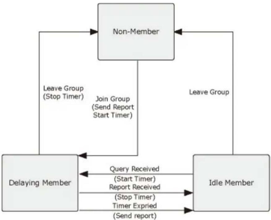
flowchart
graph TD
    A["Non-Member"] -->|Leave Group (Stop Timer)| B["Delaying Member"]
    A -->|Leave Group| C["Idle Member"]
    B -->|Query Received (Start Timer) Report Received (Stop Timer) Timer Expried (Send report)| C
    C -->|Join Group (Send Report Start Timer)| A
Figure 4-3-5-4: IGMP State Transitions
■ IGMP Querier –
A router, or multicast-enabled switch, can periodically ask their hosts if they want to receive multicast traffic. If there is more than one router/switch on the LAN performing IP multicasting, one of these devices is elected "querier" and assumes the role of querying the LAN for group members. It then propagates the service requests on to any upstream multicast switch/router to ensure that it will continue to receive the multicast service.

Multicast routers use this information, along with a multicast routing protocol such as DVMRP or PIM, to support IP multicasting across the Internet.
4.3.5.2 Profile Table
This page provides IPMC Profile related configurations. The IPMC profile is used to deploy the access control on IP multicast streams. It is allowed to create at maximum 64 Profiles with at maximum 128 corresponding rules for each. The Profile Table screen in Figure 4-3-5-5 appears.
IPMC Profile Configurations

IPMC Profile Table Setting

Figure 4-3-5-5: IPMC Profile Configuration Page
The page includes the following fields:
| Object Description | |
| • Global Profile Mode | Enable/Disable the Global IPMC Profile. System starts to do filtering based on profile settings only when the global profile mode is enabled. |
| • Delete | Check to delete the entry. The designated entry will be deleted during the next save. |
| • Profile Name | The name used for indexing the profile table. Each entry has the unique name which is composed of at maximum 16 alphabetic and numeric characters. At least one alphabet must be present. |
| • Profile Description | Additional description, which is composed of at maximum 64 alphabetic and numeric characters, about the profile. No blank or space characters are permitted as part of description. Use "_" or "-" to separate the description sentence. |
| • Rule | When the profile is created, click the edit button to enter the rule setting page of the designated profile. Summary about the designated profile will be shown by clicking the view button. You can manage or inspect the rules of the designated profile by using the following buttons: ☐: List the rules associated with the designated profile. ☑: Adjust the rules associated with the designated profile. |
Buttons
Add New IPMC Profile: Click to add new IPMC profile. Specify the name and configure the new entry. Click "Save".
Apply : Click to apply changes
Reset: Click to undo any changes made locally and revert to previously saved values.
4.3.5.3 Address Entry
This page provides address range settings used in IPMC profile. The address entry is used to specify the address range that will be associated with IPMC Profile. It is allowed to create at maximum 128 address entries in the system. The Profile Table screen in Figure 4-3-5-6 appears.
IPMC Profile Address Configuration

Navigate Address Entry Setting in IPMC Profile by 20 entries per page.
| Delete | Entry Name | Start Address | End Address |
| Delete |


Figure 4-3-5-6: IPMC Profile Address Configuration Page
The page includes the following fields:
| Object Description | |
| Delete | Check to delete the entry.The designated entry will be deleted during the next save. |
| Entry Name | The name used for indexing the address entry table.Each entry has the unique name which is composed of at maximum 16 alphabetic and numeric characters. At least one alphabet must be present. |
| Start Address | The starting IPv4/IPv6 Multicast Group Address that will be used as an address range. |
| End Address | The ending IPv4/IPv6 Multicast Group Address that will be used as an address range. |
Buttons
Add New Address (Range) Entry: Click to add new address range. Specify the name and configure the addresses. Click "Save".
Apply : Click to apply changes
Reset: Click to undo any changes made locally and revert to previously saved values.
Refresh: Refreshes the displayed table starting from the input fields.
|<<: Updates the table starting from the first entry in the IPMC Profile Address Configuration.
: Updates the table, starting with the entry after the last entry currently displayed.
4.3.5.4 IGMP Snooping Configuration
This page provides IGMP Snooping related configuration. The IGMP Snooping Configuration screen in Figure 4-3-5-7 appears.
IGMP Snooping Configuration
Stack Global Settings
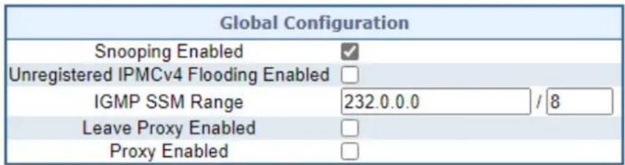
Port Related Configuration
| Port | Router Port | Fast Leave | Throttling |
| * | |||
| 1 | Auto | Unlimited | |
| 2 | Auto | Unlimited | |
| 3 | Auto | Unlimited | |
| 4 | Auto | Unlimited | |
| 5 | Auto | Unlimited | |
| 6 | Auto | Unlimited | |
| 7 | Auto | Unlimited | |
| 8 | Auto | Unlimited | |
| 9 | Auto | Unlimited | |
| 10 | Auto | Unlimited |

Figure 4-3-5-7: IGMP Snooping Configuration Page Screenshot
The page includes the following fields:
| Object Description | |
| • Snooping Enabled | Enable the Global IGMP Snooping. |
| • Unregistered IPMCv4Flooding Enabled | Enable unregistered IPMCv4 traffic flooding.The flooding control takes effect only when IGMP Snooping is enabled.When IGMP Snooping is disabled, unregistered IPMCv4 traffic flooding is alwaysactive in spite of this setting. |
| • IGMP SSM Range | SSM (Source-Specific Multicast) Range allows the SSM-aware hosts and routers run the SSM service model for the groups in the address range. |
| • Leave Proxy Enable | Enable IGMP Leave Proxy. This feature can be used to avoid forwarding unnecessary leave messages to the router side. |
| • Proxy Enable | Enable IGMP Proxy. This feature can be used to avoid forwarding unnecessary join and leave messages to the router side. |
| • Router Port | Specify which ports act as IGMP router ports. A router port is a port on the Ethernet switch that leads towards the Layer 3 multicast device or IGMP querier. The Switch forwards IGMP join or leave packets to an IGMP router port.■ Auto:Select “Auto” to have the Managed Metro Switch automatically uses the port as IGMP Router port if the port receives IGMP query packets.■ Fix:The Managed Metro Switch always uses the specified port as an IGMP Router port. Use this mode when you connect an IGMP multicast server or IP camera which applied with multicast protocol to the port.■ None:The Managed Metro Switch will not use the specified port as an IGMP Router port. The Managed Metro Switch will not keep any record of an IGMP router being connected to this port. Use this mode when you connect other IGMP multicast servers directly on the non-querier Managed Metro Switch and don’t want the multicast stream to be flooded by uplinking switch through the port that is connected to the IGMP querier. |
| • Fast Leave | Enable the fast leave on the port. |
| • Throtting | Enable to limit the number of multicast groups to which a switch port can belong. |
Buttons
Apply
: Click to apply changes
Reset
: Click to undo any changes made locally and revert to previously saved values.
4.3.5.5 IGMP Snooping VLAN Configuration
Each page shows up to 99 entries from the VLAN table, default being 20, selected through the "entries per page" input field. When first visited, the web page will show the first 20 entries from the beginning of the VLAN Table. The first displayed will be the one with the lowest VLAN ID found in the VLAN Table.
The "VLAN" input fields allow the user to select the starting point in the VLAN Table. The IGMP Snooping VLAN Configuration screen in Figure 4-3-5-8 appears.
IGMP Snooping VLAN Configuration

Start from VLAN 1 with 20 entries per page.
| VLAN ID | Snooping Enabled | Querier Election | Querier Address | Compatibility | PRI | RV | QI (sec) | QRI (0.1 sec) | LLQI (0.1 sec) | URI (sec) |
| 1 | 192.168.0 100 | IGMP-Auto | 0 | 2 | 125 | 100 | 10 | 1 |
Figure 4-3-5-8: IGMP Snooping VLAN Configuration Page Screenshot
The page includes the following fields:
| Object Description | |
| • VLAN ID | The VLAN ID of the entry. |
| • IGMP Snooping Enable | Enable the per-VLAN IGMP Snooping. Up to 8 VLANs can be selected for IGMP Snooping. |
| • Querier Election | Enable to join IGMP Querier election in the VLAN. Disable to act as an IGMP Non-Querier. |
| • Querier Address | erier AddressDefine the IPv4 address as source address used in IP header for IGMP Querier election.When the Querier address is not set, system uses IPv4 management address of the IP interface associated with this VLAN.When the IPv4 management address is not set, system uses the first available IPv4 management address.Otherwise, system uses a pre-defined value. |
| • Compatibility | Compatibility is maintained by hosts and routers taking appropriate actions depending on the versions of IGMP operating on hosts and routers within a network. The allowed selection is IGMP-Auto, Forced IGMPv1, Forced IGMPv2, Forced IGMPv3.Default compatibility value is IGMP-Auto. |
| • PRI | (PRI) Priority of Interface. It indicates the IGMP control frame priority level generated by the system. These values can be used to prioritize different classes of traffic.The allowed range is 0 (best effort) to 7 (highest), default interface priority value is 0 |
| • RV | Robustness Variable. The Robustness Variable allows tuning for the expected packet loss on a network.The allowed range is 1 to 255, default robustness variable value is 2. |
| • QI | Query Interval. The Query Interval is the interval between General Queries sent by the Querier. The allowed range is 1 to 31744 seconds, default query interval is 125 seconds. |
| • QRI | Query Response Interval. The Max Response Time used to calculate the Max Resp Code inserted into the periodic General Queries.The allowed range is 0 to 31744 in tenths of seconds, default query response interval is 100 in tenths of seconds (10 seconds). |
| • LLQI (LMQI for IGMP) | Last Member Query Interval. The Last Member Query Time is the time value represented by the Last Member Query Interval, multiplied by the Last Member Query Count.The allowed range is 0 to 31744 in tenths of seconds, default last member query interval is 10 in tenths of seconds (1 second). |
| • URI | Unsolicited Report Interval. The Unsolicited Report Interval is the time between repetitions of a host's initial report of membership in a group.The allowed range is 0 to 31744 seconds, default unsolicited report interval is 1 second. |
Buttons

Updates the table starting from the first entry in the VLAN Table, i.e. the entry with the lowest VLAN ID.

Updates the table, starting with the entry after the last entry currently displayed.

: Click to apply changes

: Click to undo any changes made locally and revert to previously saved values.
4.3.5.6 IGMP Snooping Port Group Filtering
In certain switch applications, the administrator may want to control the multicast services that are available to end users. For example, an IP/TV service based on a specific subscription plan. The IGMP filtering feature fulfills this requirement by restricting access to specified multicast services on a switch port, and IGMP throttling limits the number of simultaneous multicast groups a port can join.
IGMP filtering enables you to assign a profile to a switch port that specifies multicast groups that are permitted or denied on the port. An IGMP filter profile can contain one or more, or a range of multicast addresses; but only one profile can be assigned to a port. When enabled, IGMP join reports received on the port are checked against the filter profile. If a requested multicast group is permitted, the IGMP join report is forwarded as normal. If a requested multicast group is denied, the IGMP join report is dropped.
IGMP throttling sets a maximum number of multicast groups that a port can join at the same time. When the maximum number of groups is reached on a port, the switch can take one of two actions; either "deny" or "replace". If the action is set to deny, any new IGMP join reports will be dropped. If the action is set to replace, the switch randomly removes an existing group and replaces it with the new multicast group. The IGMP Snooping Port Group Filtering Configuration screen in Figure 4-3-5-9 appears.
IGMP Snooping Port Filtering Profile Configuration
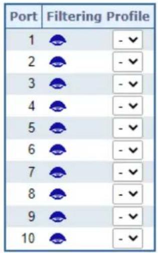
Apply Reset
Figure 4-3-5-9: IGMP Snooping Port Filtering Profile Configuration Page Screenshot
The page includes the following fields:
| Object Description | |
| • Port | The logical port for the settings. |
| • Filtering Profile | Select the IPMC Profile as the filtering condition for the specific port. Summary about the designated profile will be shown by clicking the view button |
Buttons
: Click to apply changes
: Click to undo any changes made locally and revert to previously saved values.
4.3.5.7 IGMP Snooping Status
This page provides IGMP Snooping status. The IGMP Snooping Status screen in Figure 4-3-5-10 appears.
Auto-refresh □ Refresh Clear
IGMP Snooping Status
Statistics
| VLAN ID | Querier Version | Host Version | Querier Status | Queries Transmitted | Queries Received | V1 Reports Received | V2 Reports Received | V3 Reports Received | V2 Leaves Received |
| 1 | v3 | v3 | ACTIVE | 142 | 0 | 0 | 0 | 0 | 0 |
Router Port
| Port | Status |
| 1 | - |
| 2 | - |
| 3 | - |
| 4 | - |
| 5 | - |
| 6 | - |
| 7 | - |
| 8 | - |
| 9 | - |
| 10 | - |
Figure 4-3-5-10: IGMP Snooping Status Page Screenshot
The page includes the following fields:
| Object Description | |
| • VLAN ID | The VLAN ID of the entry. |
| • Querier Version | Working Querier Version currently. |
| • Host Version | Working Host Version currently. |
| • Querier Status | Show the Querier status is "ACTIVE" or "IDLE". |
| • Querier Transmitted | The number of Transmitted Querier. |
| • Querier Received | The number of Received Querier. |
| • V1 Reports Received | The number of Received V1 Reports. |
| • V2 Reports Received | The number of Received V2 Reports. |
| • V3 Reports Received | The number of Received V3 Reports. |
| • V2 Leave Received | The number of Received V2 Leave. |
| • Router Port | Display which ports act as router ports. A router port is a port on the Ethernet switch that leads towards the Layer 3 multicast device or IGMP querier.Static denotes the specific port is configured to be a router port.Dynamic denotes the specific port is learnt to be a router port.Both denote the specific port is configured or learnt to be a router port. |
| • Port | Switch port number. |
| • Status | Indicate whether specific port is a router port or not. |
Buttons
Auto-refresh ☐: Automatic refresh occurs every 3 seconds.

Click to refresh the page immediately.
: Clears all Statistics counters.
4.3.5.8 IGMP Groups Information
Entries in the IGMP Group Table are shown on this Page. The IGMP Group Table is sorted first by VLAN ID, and then by group. Each page shows up to 99 entries from the IGMP Group table, default being 20, selected through the "entries per page" input field. When first visited, the web page will show the first 20 entries from the beginning of the IGMP Group Table. The "Start from VLAN", and "group" input fields allow the user to select the starting point in the IGMP Group Table. The IGMP Groups Information screen in Figure 4-3-5-11 appears.
IGMP Snooping Group Information
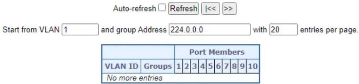
Figure 4-3-5-11: IGMP Snooping Groups Information Page Screenshot
The page includes the following fields:
| Object Description | |
| • VLAN ID | VLAN ID of the group. |
| • Groups | Group address of the group displayed. |
| • Port Members | Ports under this group. |
Buttons
Auto-refresh ☐: Automatic refresh occurs every 3 seconds.

Refreshes the displayed table starting from the input fields.

Updates the table, starting with the first entry in the IGMP Group Table.

Updates the table, starting with the entry after the last entry currently displayed.
4.3.5.9 IGMPv3 Information
Entries in the IGMP SFM Information Table are shown on this page. The IGMP SFM (Source-Filtered Multicast) Information Table also contains the SSM (Source-Specific Multicast) information. This table is sorted first by VLAN ID, then by group, and then by Port. Different source addresses belong to the same group are treated as single entry. The IGMPv3 Information screen in Figure 4-3-5-12 appears.
IGMP SFM Information
Auto-refresh □ Refresh |<< >>
Start from VLAN 1 and Group 224.0.0.0 with 20 entries per page.
| VLAN ID | Group | Port | Mode | Source Address | Type | Hardware Filter/Switch |
| No more entries | ||||||
Figure 4-3-5-12: IGMPv3 Information Page Screenshot
The page includes the following fields:
| Object Description | |
| • VLAN ID | VLAN ID of the group. |
| • Groups | Group address of the group displayed. |
| • Port | Switch port number. |
| • Mode | Indicates the filtering mode maintained per (VLAN ID, port number, Group Address) basis. It can be either Include or Exclude. |
| • Source Address | IP Address of the source.Currently, the maximum number of IPv4 source address for filtering (per group) is 8.When there is no any source filtering address, the text "None" is shown in the Source Address field. |
| • Type | Indicates the Type. It can be either Allow or Deny. |
| • Hardware Filter/Switch | Indicates whether data plane destined to the specific group address from the source IPv4 address could be handled by chip or not. |
Buttons
Auto-refresh ☐: Automatic refresh occurs every 3 seconds.
Refresh
Refreshes the displayed table starting from the input fields.
k<
Updates the table starting from the first entry in the IGMP SFM Information Table.
: Updates the table, starting with the entry after the last entry currently displayed.
4.3.6 MLD Snooping
4.3.6.1 MLD Snooping Configuration
This page provides MLD Snooping related configuration. The MLD Snooping Configuration screen in Figure 4-3-6-1 appears.
MLD Snooping Configuration

Port Related Configuration
| Port | Router Port | Fast Leave | Throttling |
| * | |||
| 1 | Auto | Unlimited | |
| 2 | Auto | Unlimited | |
| 3 | Auto | Unlimited | |
| 4 | Auto | Unlimited | |
| 5 | Auto | Unlimited | |
| 6 | Auto | Unlimited | |
| 7 | Auto | Unlimited | |
| 8 | Auto | Unlimited | |
| 9 | Auto | Unlimited | |
| 10 | Auto | Unlimited |
Apply Reset
Figure 4-3-6-1: MLD Snooping Configuration Page Screenshot
The page includes the following fields:
| Object Description | |
| • Snooping Enabled | Enable the Global MLD Snooping. |
| • Unregistered IPMCv6Flooding enabled | Enable unregistered IPMCv6 traffic flooding.The flooding control takes effect only when MLD Snooping is enabled.When MLD Snooping is disabled, unregistered IPMCv6 traffic flooding is always active in spite of this setting. |
| • MLD SSM Range | SSM (Source-Specific Multicast) Range allows the SSM-aware hosts and routers run the SSM service model for the groups in the address range. |
| • Leave Proxy Enable | Enable MLD Leave Proxy. This feature can be used to avoid forwarding unnecessary leave messages to the router side. |
| Proxy Enable | Enable MLD Proxy. This feature can be used to avoid forwarding unnecessary join and leave messages to the router side. |
| Router Port | Specify which ports act as router ports. A router port is a port on the Ethernet switch that leads towards the Layer 3 multicast device or MLD querier.If an aggregation member port is selected as a router port, the whole aggregation will act as a router port. The allowed selection isAuto, Fix, Fone, default compatibility value is Auto. |
| Fast Leave | Enable the fast leave on the port. |
| Throtting | Enable to limit the number of multicast groups to which a switch port can belong. |
Buttons
Apply
: Click to apply changes
Reset
: Click to undo any changes made locally and revert to previously saved values.
4.3.6.2 MLD Snooping VLAN Configuration
Each page shows up to 99 entries from the VLAN table, default being 20, selected through the "entries per page" input field. When first visited, the web page will show the first 20 entries from the beginning of the VLAN Table. The first displayed will be the one with the lowest VLAN ID found in the VLAN Table.
The "VLAN" input fields allow the user to select the starting point in the VLAN Table. The MLD Snooping VLAN Configuration screen in Figure 4-3-6-2 appears.
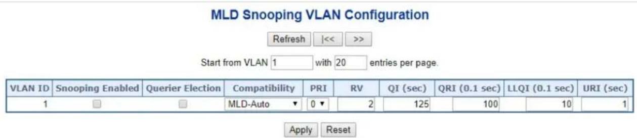
Figure 4-3-6-2: IGMP Snooping VLAN Configuration Page Screenshot
The page includes the following fields:
| Object Description | |
| • VLAN ID | The VLAN ID of the entry. |
| • MLD Snooping Enable | Enable the per-VLAN MLD Snooping. Up to 8 VLANs can be selected for MLD Snooping. |
| • Querier Election | Enable to join MLD Querier election in the VLAN. Disable to act as a MLDNon-Querier. |
| • Compatibility | Compatibility is maintained by hosts and routers taking appropriate actions depending on the versions of MLD operating on hosts and routers within a network. The allowed selection is MLD-Auto, Forced MLDv1, Forced MLDv2, default compatibility value is MLD-Auto. |
| • PRI | (PRI) Priority of Interface. It indicates the MLD control frame priority level generated by the system. These values can be used to prioritize different classes of traffic. The allowed range is 0 (best effort) to 7 (highest), default interface priority value is 0 |
| • RV | Robustness Variable. The Robustness Variable allows tuning for the expected packet loss on a network. The allowed range is 1 to 255, default robustness variable value is 2. |
| • QI | Query Interval. The Query Interval is the interval between General Queries sent by the Querier. The allowed range is 1 to 31744 seconds, default query interval is 125 seconds. |
| • QRI | Query Response Interval. The Max Response Time used to calculate the Max Resp Code inserted into the periodic General Queries. The allowed range is 0 to 31744 in tenths of seconds, default query response interval is 100 in tenths of seconds (10 seconds). |
| • LLQI (LMQI for IGMP) | Last Member Query Interval. The Last Member Query Time is the time value represented by the Last Member Query Interval, multiplied by the Last Member Query Count. The allowed range is 0 to 31744 in tenths of seconds, default last member query interval is 10 in tenths of seconds (1 second). |
| • URI | Unsolicited Report Interval. The Unsolicited Report Interval is the time between repetitions of a host's initial report of membership in a group. The allowed range is 0 to 31744 seconds, default unsolicited report interval is 1 second. |
Buttons

Refreshes the displayed table starting from the "VLAN" input fields.

Updates the table starting from the first entry in the VLAN Table, i.e. the entry with the lowest VLAN ID.

Updates the table, starting with the entry after the last entry currently displayed.

: Click to apply changes

: Click to undo any changes made locally and revert to previously saved values.
4.3.6.3 MLD Snooping Port Group Filtering
In certain switch applications, the administrator may want to control the multicast services that are available to end users. For example, an IP/TV service based on a specific subscription plan. The MLD filtering feature fulfills this requirement by restricting access to specified multicast services on a switch port, and MLD throttling limits the number of simultaneous multicast groups a port can join.
MLD filtering enables you to assign a profile to a switch port that specifies multicast groups that are permitted or denied on the port. A MLD filter profile can contain one or more, or a range of multicast addresses; but only one profile can be assigned to a port. When enabled, MLD join reports received on the port are checked against the filter profile. If a requested multicast group is permitted, the MLD join report is forwarded as normal. If a requested multicast group is denied, the MLD join report is dropped.
MLD throttling sets a maximum number of multicast groups that a port can join at the same time. When the maximum number of groups is reached on a port, the switch can take one of two actions; either "deny" or "replace". If the action is set to deny, any new MLD join reports will be dropped. If the action is set to replace, the switch randomly removes an existing group and replaces it with the new multicast group. The MLD Snooping Port Group Filtering Configuration screen in Figure 4-3-6-3 appears.
MLD Snooping Port Filtering Profile Configuration
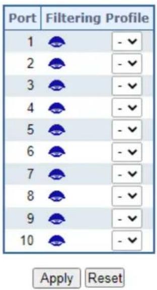
Figure 4-3-6-3: MLD Snooping Port Group Filtering Configuration Page Screenshot
The page includes the following fields:
| Object Description | |
| • Port | The logical port for the settings. |
| • Filtering Profile | Select the IPMC Profile as the filtering condition for the specific port. Summary about the designated profile will be shown by clicking the view button. |
Buttons
Click to apply changes
Click to undo any changes made locally and revert to previously saved values.
4.3.6.4 MLD Snooping Status
This page provides MLD Snooping status. The IGMP Snooping Status screen in Figure 4-3-6-4 appears.

MLD Snooping Status
Statistics
| VLAN ID | Querier Version | Host Version | Querier Status | Queries Transmitted | Queries Received | V1 Reports Received | V2 Reports Received | V1 Leaves Received |
| 1 | v2 | v1 | ACTIVE | 2014 | 0 | 15810 | 878 | 545 |
Router Port
| Port | Status |
| 1 | - |
| 2 | - |
| 3 | - |
| 4 | - |
| 5 | - |
| 6 | - |
| 7 | - |
| 8 | - |
| 9 | - |
| 10 | - |
Figure 4-3-6-4: MLD Snooping Status Page Screenshot
The page includes the following fields:
| Object Description | |
| • VLAN ID | The VLAN ID of the entry. |
| • Querier Version | Working Querier Version currently. |
| • Host Version | Working Host Version currently. |
| • Querier Status | Shows the Querier status is "ACTIVE" or "IDLE"."DISABLE" denotes the specific interface is administratively disabled. |
| • Querier Transmitted | The number of Transmitted Querier. |
| • Querier Received | The number of Received Querier. |
| • V1 Reports Received | The number of Received V1 Reports. |
| • V2 Reports Received | The number of Received V2 Reports. |
| • V1 Leave Received | The number of Received V1 Leaves. |
| • Router Port | Display which ports act as router ports. A router port is a port on the Ethernet switch that leads towards the Layer 3 multicast device or MLD querier.Static denotes the specific port is configured to be a router port.Dynamic denotes the specific port is learnt to be a router port.Both denote the specific port is configured or learnt to be a router port. |
| • Port | Switch port number. |
| • Status | Indicates whether specific port is a router port or not. |
Buttons
Auto-refresh ☐: Automatic refresh occurs every 3 seconds.


Automatic refresh occurs every 3 seconds.
Click to refresh the page immediately.
: Clears all Statistics counters.
4.3.6.5 MLD Groups Information
Entries in the MLD Group Table are shown on this page. The MLD Group Table is sorted first by VLAN ID, and then by group. Each page shows up to 99 entries from the MLD Group table, default being 20, selected through the "entries per page" input field. When first visited, the web page will show the first 20 entries from the beginning of the MLD Group Table.
The "Start from VLAN", and "group" input fields allow the user to select the starting point in the MLD Group Table. The MLD Groups Information screen in Figure 4-3-6-5 appears.
MLD Snooping Group Information

Start from VLAN 1 and group Address ff00: with 20 entries per page.
| Port Members | |||||||||||
| VLAN ID | Groups | 1 | 2 | 3 | 4 | 5 | 6 | 7 | 8 | 9 | 10 |
| 1 | ff02::c | ✓ | |||||||||
| 1 | ff02::fb | ✓ | |||||||||
| 1 | ff02::1:3 | ✓ | |||||||||
| 1 | ff02::1:ff00:0 | ✓ | |||||||||
| 1 | ff02::1:ff00:665 | ✓ | |||||||||
| 1 | ff02::1:ff1a:a605 | ✓ | |||||||||
| 1 | ff02::1:ff1a:b235 | ✓ | |||||||||
| 1 | ff02::1:ff1e:19e9 | ✓ | |||||||||
| 1 | ff02::1:ff24:ad12 | ✓ | |||||||||
| 1 | ff02::1:ff25:827c | ✓ | |||||||||
| 1 | ff02::1:ff2d:d7d | ✓ | |||||||||
| 1 | ff02::1:ff2f:4a02 | ✓ | |||||||||
| 1 | ff02::1:ff34:200 | ✓ | |||||||||
| 1 | ff02::1:ff34:3131 | ✓ | |||||||||
| 1 | ff02::1:ff37:aa10 | ✓ | |||||||||
| 1 | ff02::1:ff3d:acb1 | ✓ | |||||||||
| 1 | ff02::1:ff43:bb6e | ✓ | |||||||||
| 1 | ff02::1:ff44:d567 | ✓ | |||||||||
| 1 | ff02::1:ff45:7273 | ✓ | |||||||||
| 1 | ff02::1:ff48:a519 | ✓ | |||||||||
Figure 4-3-6-5: MLD Snooping Groups Information Page Screenshot
The page includes the following fields:
| Object Description | |
| • VLAN ID | VLAN ID of the group. |
| • Groups | Group address of the group displayed. |
| • Port Members | Ports under this group. |
Buttons
Auto-refresh ☐: Automatic refresh occurs every 3 seconds.

☐: Automatic refresh occurs every 3 seconds.

Updates the table, starting with the first entry in the IGMP Group Table.

Updates the table, starting with the entry after the last entry currently displayed.
4.3.6.6 MLDv2 Information
Entries in the MLD SFM Information Table are shown on this page. The MLD SFM (Source-Filtered Multicast) Information Table also contains the SSM (Source-Specific Multicast) information. This table is sorted first by VLAN ID, then by group, and then by Port. Different source addresses belong to the same group are treated as single entry. Each page shows up to 99 entries from the MLD SFM Information table, default being 20, selected through the "entries per page" input field. When first visited, the web Page will show the first 20 entries from the beginning of the MLD SFM Information Table.
The "Start from VLAN", and "group" input fields allow the user to select the starting point in the MLD SFM Information Table. The MLDv2 Information screen in Figure 4-3-6-6 appears.
MLD SFM Information
Auto-refresh □ Refresh |<< >>
Start from VLAN 1 and Group ff00:: with 20 entries per page.
| VLAN ID | Group | Port | Mode | Source Address | Type | Hardware Filter/Switch |
| 1 | ff02::c | 1 | Exclude | None | Deny | Yes |
| 1 | ff02::fb | 1 | Exclude | None | Deny | Yes |
| 1 | ff02::1:3 | 1 | Exclude | None | Deny | Yes |
| 1 | ff02::1:ff00:0 | 1 | Exclude | None | Deny | Yes |
| 1 | ff02::1:ff00:665 | 1 | Exclude | None | Deny | Yes |
| 1 | ff02::1:ff1a:a605 | 1 | Exclude | None | Deny | Yes |
| 1 | ff02::1:ff1a:b235 | 1 | Exclude | None | Deny | Yes |
| 1 | ff02::1:ff1e:19e9 | 1 | Exclude | None | Deny | Yes |
| 1 | ff02::1:ff24:ad12 | 1 | Exclude | None | Deny | Yes |
| 1 | ff02::1:ff25:827c | 1 | Exclude | None | Deny | Yes |
| 1 | ff02::1:ff2d:d7d | 1 | Exclude | None | Deny | Yes |
| 1 | ff02::1:ff2f:4a02 | 1 | Exclude | None | Deny | Yes |
| 1 | ff02::1:ff34:200 | 1 | Exclude | None | Deny | Yes |
| 1 | ff02::1:ff34:3131 | 1 | Exclude | None | Deny | Yes |
| 1 | ff02::1:ff37:aa10 | 1 | Exclude | None | Deny | Yes |
| 1 | ff02::1:ff3d:acb1 | 1 | Exclude | None | Deny | Yes |
| 1 | ff02::1:ff43:bb6e | 1 | Exclude | None | Deny | Yes |
| 1 | ff02::1:ff44:d567 | 1 | Exclude | None | Deny | Yes |
| 1 | ff02::1:ff45:7273 | 1 | Exclude | None | Deny | Yes |
| 1 | ff02::1:ff48:a519 | 1 | Exclude | None | Deny | Yes |
Figure 4-3-6-6: MLD SSM Information Page Screenshot
The page includes the following fields:
| Object Description | |
| • VLAN ID | VLAN ID of the group. |
| • Group | Group address of the group displayed. |
| • Port | Switch port number. |
| • Mode | Indicates the filtering mode maintained per (VLAN ID, port number, Group Address) basis. It can be either Include or Exclude. |
| • Source Address | IP Address of the source. Currently, system limits the total number of IP source addresses for filtering to be 128. |
| • Type | Indicates the Type. It can be either Allow or Deny. |
| • Hardware Filter/Switch | Indicates whether data plane destined to the specific group address from the source IPv6 address could be handled by chip or not. |
Buttons
Auto-refresh
☐: Automatic refresh occurs every 3 seconds.
Refresh
Refreshes the displayed table starting from the input fields.
k
Updates the table starting from the first entry in the MLD SFM Information Table.
Updates the table, starting with the entry after the last entry currently displayed.
4.3.7 MVR (Multicast VLAN Registration)
The MVR feature enables multicast traffic forwarding on the Multicast VLANs.
In a multicast television application, a PC or a network television or a set-top box can receive the multicast stream.
■ Multiple set-top boxes or PCs can be connected to one subscriber port, which is a switch port configured as an MVR receiver port. When a subscriber selects a channel, the set-top box or PC sends an IGMP/MLD report message to Switch A to join the appropriate multicast group address.
■ Uplink ports that send and receive multicast data to and from the multicast VLAN are called MVR source ports.
It is allowed to create at maximum 8 MVR VLANs with corresponding channel settings for each Multicast VLAN. There will be totally at maximum 256 group addresses for channel settings.
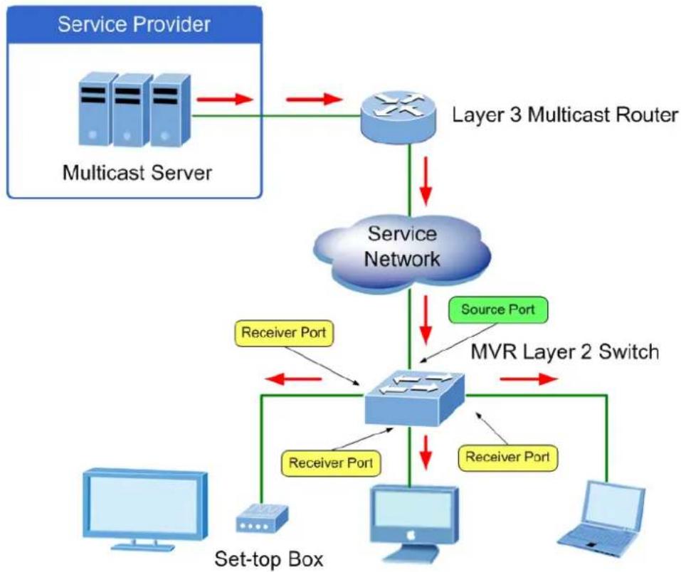
flowchart
graph TD
    A["Service Provider"] --> B["Multicast Server"]
    B --> C["Service Network"]
    C --> D["MVR Layer 2 Switch"]
    D --> E["Server"]
    D --> F["Server"]
    D --> G["Computer"]
    D --> H["Laptop"]
    C --> I["Source Port"]
    I --> D
    C --> J["Receiver Port"]
    J --> D
    C --> K["Receiver Port"]
    K --> D
    style A fill:#cce5ff,stroke:#333
    style B fill:#cce5ff,stroke:#333
    style C fill:#cce5ff,stroke:#333
    style D fill:#cce5ff,stroke:#333
    style E fill:#cce5ff,stroke:#333
    style F fill:#cce5ff,stroke:#333
    style G fill:#cce5ff,stroke:#333
    style H fill:#cce5ff,stroke:#333
    style I fill:#cce5ff,stroke:#333
    style J fill:#cce5ff,stroke:#333
    style K fill:#cce5ff,stroke:#333
    style L fill:#cce5ff,stroke:#333
4.3.7.1 MVR Configuration
. This page provides MVR related configuration. The MVR screen in Figure 4-3-7-1 appears
MVR Configurations

VLAN Interface Setting (Role [I:Inactive / S:Source / R:Receiver])
| Delete | MVR VID | MVR Name | Querier Election | IGMP Address | Mode | Tagging | Priority | LLQI | Interface Channel Profile |
MVR source ports are not recommended to be overlapped with management VLAN ports.
Add New MVR VLAN
Immediate Leave Setting
| Port | Immediate Leave |
| * | |
| 1 | Disabled |
| 2 | Disabled |
| 3 | Disabled |
| 4 | Disabled |
| 5 | Disabled |
| 6 | Disabled |
| 7 | Disabled |
| 8 | Disabled |
| 9 | Disabled |
| 10 | Disabled |
Apply Reset
Figure 4-3-7-1: MVR Configuration Page Screenshot
The page includes the following fields:
| Object Description | |
| • MVR Mode | Enable/Disable the Global MVR.The Unregistered Flooding control depends on the current configuration in IGMP/MLD Snooping.It is suggested to enable Unregistered Flooding control when the MVR group table is full. |
| • Delete | Check to delete the entry. The designated entry will be deleted during the next save. |
| • MVR VID | Specify the Multicast VLAN ID.Be Caution: MVR source ports are not recommended to be overlapped with management VLAN ports. |
| • MVR Name | MVR Name is an optional attribute to indicate the name of the specific MVR VLAN. Maximum length of the MVR VLAN Name string is 16. MVR VLAN Namecan only contain alphabets or numbers. When the optional MVR VLAN name is given, it should contain at least one alphabet. MVR VLAN name can be edited for the existing MVR VLAN entries or it can be added to the new entries. |
| • Querier Election | Enable to join IGMP Querier election in the VLAN. Disable to act as an IGMP Non-Querier. |
| • IGMP Address | Define the IPv4 address as source address used in IP header for IGMP control frames. The default IGMP address is not set (0.0.0.0).When the IGMP address is not set, system uses IPv4 management address of the IP interface associated with this VLAN.When the IPv4 management address is not set, system uses the first available IPv4 management address. Otherwise, system uses a pre-defined value. By default, this value will be 192.0.2.1. |
| • Mode | Specify the MVR mode of operation. In Dynamic mode, MVR allows dynamic MVR membership reports on source ports. In Compatible mode, MVR membership reports are forbidden on source ports. The default is Dynamic mode. |
| • Tagging | Specify whether the traversed IGMP/MLD control frames will be sent as Untagged or Tagged with MVR VID. The default is Tagged. |
| • Priority | Specify how the traversed IGMP/MLD control frames will be sent in prioritized manner. The default Priority is 0. |
| • LLQI | Define the maximum time to wait for IGMP/MLD report memberships on a receiver port before removing the port from multicast group membership. The value is in units of tenths of a seconds. The range is from 0 to 31744. The default LLQI is 5 tenths or one-half second. |
| • Interface Channel Profile | When the MVR VLAN is created, select the IPMC Profile as the channel filtering condition for the specific MVR VLAN. Summary about the Interface Channel Profiling (of the MVR VLAN) will be shown by clicking the view button. Profile selected for designated interface channel is not allowed to have overlapped permit group address. |
| • Port | The logical port for the settings. |
| • Port Role | Configure an MVR port of the designated MVR VLAN as one of the following roles.Inactive: The designated port does not participate MVR operations.Source: Configure uplink ports that receive and send multicast data as source ports. Subscribers cannot be directly connected to source ports.Receiver: Configure a port as a receiver port if it is a subscriber port and should only receive multicast data. It does not receive data unless it becomes a member of the multicast group by issuing IGMP/MLD messages.Be Caution: MVR source ports are not recommended to be overlapped with management VLAN ports.Select the port role by clicking the Role symbol to switch the setting. I indicates Inactive; S indicates Source; R indicates Receiver The default Role is Inactive. |
| • Immediate Leave | Enable the fast leave on the port. System will remove group record and stop forwarding data upon receiving the IGMPv2/MLDv1 leave message without sending last member query messages. It is recommended to enable this feature only when a single IGMPv2/MLDv1 host is connected to the specific port. |
Buttons
Add New MVR VLAN
Click to add new MVR VLAN. Specify the VID and configure the new entry. Click "Save"
Apply
: Click to apply changes
Reset
: Click to undo any changes made locally and revert to previously saved values.
4.3.7.2 MVR Status
This page provides MVR status. The MVR Status screen in Figure 4-3-7-2 appears.
| VLAN ID | IGMP/MLD Queries Received | IGMP/MLD Queries Transmitted | IGMPv1 Joins Received | IGMPv2/MLDv1 Reports Received | IGMPv3/MLDv2 Reports Received | IGMPv2/MLDv1 Leaves Received |
| No more entries | ||||||
| Auto-refresh ☐ Refresh Clear | ||||||
Figure 4-3-7-2: MVR Status Page Screenshot
The page includes the following fields:
| Object Description | |
| • VLAN ID | The Multicast VLAN ID. |
| • IGMP/MLD Queries Received | The number of Received Queries for IGMP and MLD, respectively. |
| • IGMP/MLD Queries Transmitted | The number of Transmitted Queries for IGMP and MLD, respectively. |
| • IGMPv1 Joins Received | The number of Received IGMPv1 Joins. |
| • IGMPv2/MLDv1 Reports Received | The number of Received IGMPv2 Joins and MLDv1 Reports, respectively. |
| • IGMPv3/MLDv2 Reports Received | The number of Received IGMPv1 Joins and MLDv2 Reports, respectively. |
| • IGMPv2/MLDv1 Leaves Received | The number of Received IGMPv2 Leaves and MLDv1 Dones, respectively. |
Buttons
Auto-refresh

Automatic refresh occurs every 3 seconds.
Refresh
Click to refresh the page immediately.
Clear
: Clears all Statistics counters.
4.3.7.3 MVR Groups Information
Entries in the MVR Group Table are shown on this page. The MVR Group Table is sorted first by VLAN ID, and then by group. Each page shows up to 99 entries from the MVR Group table, default being 20, selected through the "entries per page" input field. When first visited, the web page will show the first 20 entries from the beginning of the MVR Group Table.
The "Start from VLAN", and "group" input fields allow the user to select the starting point in the MVR Group Table. The MVR Groups Information screen in Figure 4-3-7-3 appears.
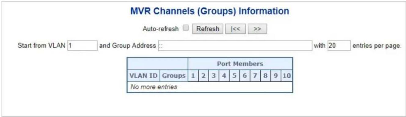
Figure 4-3-7-3: MVR Groups Information Page Screenshot
The page includes the following fields:
| Object Description | |
| • VLAN | VLAN ID of the group. |
| • Groups | Group ID of the group displayed. |
| • Port Members | Ports under this group. |
Buttons
Auto-refresh ☐: Automatic refresh occurs every 3 seconds.
Refresh: Refreshes the displayed table starting from the input fields.
k: Updates the table starting from the first entry in the MVR Channels (Groups) Information Table.
: Updates the table, starting with the entry after the last entry currently displayed.
4.3.7.4 MVR SFM Information
Entries in the MVR SFM Information Table are shown on this page. The MVR SFM (Source-Filtered Multicast) Information Table also contains the SSM (Source-Specific Multicast) information. This table is sorted first by VLAN ID, then by group, and then by Port. Different source addresses belong to the same group are treated as single entry.
Each page shows up to 99 entries from the MVR SFM Information Table, default being 20, selected through the "entries per page" input field. When first visited, the web page will show the first 20 entries from the beginning of the MVR SFM Information Table.
The "Start from VLAN", and "Group Address" input fields allow the user to select the starting point in the MVR SFM Information Table. The MVR SFM Information screen in Figure 4-3-7-4 appears.
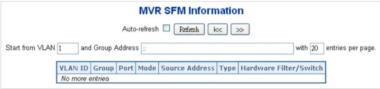
Figure 4-3-7-4: MVR SFM Information Page Screenshot
The page includes the following fields:
| Object Description | |
| • VLAN ID | VLAN ID of the group. |
| • Group | Group address of the group displayed. |
| • Port | Switch port number. |
| • Mode | Indicates the filtering mode maintained per (VLAN ID, port number, Group Address) basis. It can be either Include or Exclude. |
| • Source Address | IP Address of the source. Currently, system limits the total number of IP source addresses for filtering to be 128. When there is no any source filtering address, the text "None" is shown in the Source Address field. |
| • Type | Indicates the Type. It can be either Allow or Deny. |
| • Hardware Filter/Switch | Indicates whether data plane destined to the specific group address from the source IPv4/IPv6 address could be handled by chip or not. |
Buttons
Auto-refresh ☐: Automatic refresh occurs every 3 seconds.
Refresh: Refreshes the displayed table starting from the input fields.
Updates the table starting from the first entry in the MVR SFM Information Table.
4.3.8 LLDP
4.3.8.1 Link Layer Discovery Protocol
Link Layer Discovery Protocol (LLDP) is used to discover basic information about neighboring devices on the local broadcast domain. LLDP is a Layer 2 protocol that uses periodic broadcasts to advertise information about the sending device. Advertised information is represented in Type Length Value (TLV) format according to the IEEE 802.1ab standard, and can include details such as device identification, capabilities and configuration settings. LLDP also defines how to store and maintain information gathered about the neighboring network nodes it discovers.
Link Layer Discovery Protocol - Media Endpoint Discovery (LLDP-MED) is an extension of LLDP intended for managing endpoint devices such as Voice over IP phones and network switches. The LLDP-MED TLVs advertise information such as network policy, power, inventory, and device location details. LLDP and LLDP-MED information can be used by SNMP applications to simplify troubleshooting, enhance network management, and maintain an accurate network topology.
4.3.8.2 LLDP Configuration
This page allows the user to inspect and configure the current LLDP port settings. The LLDP Configuration screen in Figure 4-3-8-1 appears.
LLDP Configuration
LLDP Parameters
| Tx Interval | 30 | seconds |
| Tx Hold | 4 | times |
| Tx Delay | 2 | seconds |
| Tx Reinit | 2 | seconds |
LLDP Port Configuration
| Optional TLVs | |||||||
| Port | Mode | CDP Aware | Trap | Remote Port ID | System Name | System Capabilities | Management Address |
| * | |||||||
| 1 | Disabled | ||||||
| 2 | Disabled | ||||||
| 3 | Disabled | ||||||
| 4 | Disabled | ||||||
| 5 | Disabled | ||||||
| 6 | Disabled | ||||||
| 7 | Disabled | ||||||
| 8 | Disabled | ||||||
| 9 | Disabled | ||||||
| 10 | Disabled | ||||||
Figure 4-3-8-1: LLDP Configuration Page Screenshot
The page includes the following fields:
LLDP Parameters
| Object Description | |
| • Tx Interval | The switch is periodically transmitting LLDP frames to its neighbors for having the network discovery information up-to-date. The interval between each LLDP frame is determined by the Tx Interval value. Valid values are restricted to 5 - 32768 seconds.Default: 30 secondsThis attribute must comply with the following rule:(Transmission Interval * Hold Time Multiplier) ≤65536, and Transmission Interval >= (4 * Delay Interval) |
| • Tx Hold | Each LLDP frame contains information about how long the information in the LLDP frame shall be considered valid. The LLDP information valid period is set to Tx Hold multiplied by Tx Interval seconds. Valid values are restricted to 2 - 10 times.TTL in seconds is based on the following rule:(Transmission Interval * Holdtime Multiplier) ≤ 65536.Therefore, the default TTL is 4*30 = 120 seconds. |
| • Tx Delay | If some configuration is changed (e.g. the IP address) a new LLDP frame is transmitted, but the time between the LLDP frames will always be at least the value of Tx Delay seconds. Tx Delay cannot be larger than 1/4 of the Tx Interval value. Valid values are restricted to 1 - 8192 seconds.This attribute must comply with the rule:(4 * Delay Interval) ≤Transmission Interval |
| • Tx Reinit | When a port is disabled, LLDP is disabled or the switch is rebooted a LLDP shutdown frame is transmitted to the neighboring units, signaling that the LLDP information isn't valid anymore. Tx Reinit controls the amount of seconds between the shutdown frame and a new LLDP initialization. Valid values are restricted to 1 - 10 seconds. |
LLDP Port Configuration
The LLDP port settings relate to the switch, as reflected by the page header.
| Object Description | |
| • Port | The switch port number of the logical LLDP port. |
| • Mode | Select LLDP mode.■ Rx only The switch will not send out LLDP information, but LLDP information from neighbor units is analyzed.■ Tx only The switch will drop LLDP information received from neighbors, but will send out LLDP information.■ Disabled The switch will not send out LLDP information, and will drop LLDP information received from neighbors.■ Enabled The switch will send out LLDP information, and will analyze LLDP information received from neighbors. |
| • CDP Aware | Select CDP awareness.The CDP operation is restricted to decoding incoming CDP frames (The switch doesn't transmit CDP frames). CDP frames are only decoded if LLDP on the port is enabled.Only CDP TLVs that can be mapped to a corresponding field in the LLDP neighbours' table are decoded. All other TLVs are discarded (Unrecognized CDP TLVs and discarded CDP frames are not shown in the LLDP statistics.). CDP TLVs are mapped onto LLDP neighbours' table as shown below.CDP TLV "Device ID" is mapped to the LLDP "Chassis ID" field.CDP TLV "Address" is mapped to the LLDP "Management Address" field. The CDP address TLV can contain multiple addresses, but only the first address is shown in the LLDP neighbours table.CDP TLV "Port ID" is mapped to the LLDP "Port ID" field.CDP TLV "Version and Platform" is mapped to the LLDP "System Description" field.Both the CDP and LLDP support "system capabilities", but the CDP capabilities cover capabilities that are not part of the LLDP. These capabilities are shown as "others" in the LLDP neighbours' table.If all ports have CDP awareness disabled the switch forwards CDP frames received from neighbour devices. If at least one port has CDP awareness enabled all CDP frames are terminated by the switch.Note: When CDP awareness on a port is disabled the CDP information isn't removed immediately, but gets removed when the hold time is exceeded. |
| • Port Description | Optional TLV: When checked the "port description" is included in LLDP information transmitted. |
| • System Name | Optional TLV: When checked the "system name" is included in LLDP information transmitted. |
| • System Description | Optional TLV: When checked the "system description" is included in LLDP information transmitted. |
| • System Capabilities | Optional TLV: When checked the "system capability" is included in LLDP information transmitted. |
| • Management Address | Optional TLV: When checked the "management address" is included in LLDP information transmitted. |
Buttons
Apply
: Click to apply changes
Reset
: Click to undo any changes made locally and revert to previously saved values.
4.3.8.3 LLDP Neighbors
This page provides a status overview for all LLDP neighbors. The displayed table contains a row for each port on which an LLDP neighbor is detected. The LLDP Neighbor Information screen in Figure 4-3-8-2 appears.
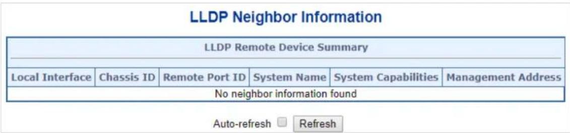
Figure 4-3-8-2: LLDP Neighbor Information Page Screenshot
The page includes the following fields:
| Object Description | |
| • Local Interface | The port on which the LLDP frame was received. |
| • Chassis ID | The Chassis ID is the identification of the neighbor's LLDP frames. |
| • Remote Port ID | The Remote Port ID is the identification of the neighbor port. |
| • Port Description | Port Description is the port description advertised by the neighbor unit. |
| • System Name | System Name is the name advertised by the neighbor unit. |
| • System Capabilities | System Capabilities describes the neighbor unit's capabilities. The possible capabilities are:1. Other2. Repeater3. Bridge4. WLAN Access Point5. Router6. Telephone7. DOCSIS cable device8. Station only9. ReservedWhen a capability is enabled, the capability is followed by (+). If the capability is disabled, the capability is followed by (-). |
| • Management Address | Management Address is the neighbor unit's address that is used for higher layer entities to assist the discovery by the network management. This could for instance hold the neighbor's IP address. |
Buttons
Auto-refresh ☐: Check this box to refresh the page automatically. Automatic refresh occurs every 3 seconds.
Refresh
Click to refresh the page immediately.
4.3.8.4 LLDP-MED Configuration
This page allows you to configure the LLDP-MED. The LLDPMED Configuration screen in Figure 4-3-8-3 appears.
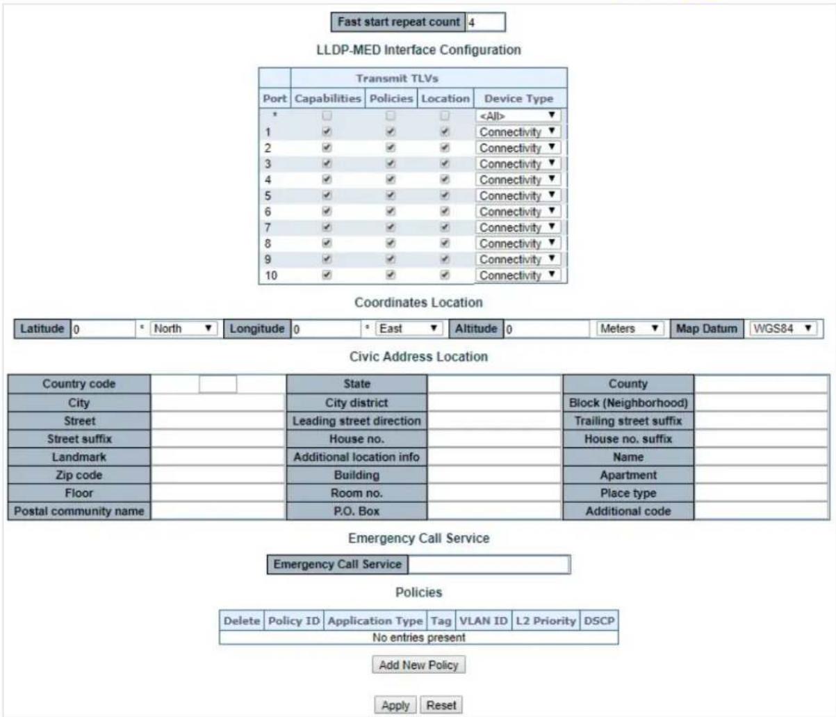
Figure 4-3-8-3: LLDPMED Configuration Page Screenshot
The page includes the following fields:
Fast start repeat count
| Object Description | |
| • Fast start repeat count | Rapid startup and Emergency Call Service Location Identification Discovery of endpoints is a critically important aspect of VoIP systems in general. In addition, it is best to advertise only those pieces of information which are specifically relevant to particular endpoint types (for example only advertise the voice network policy to permitted voice-capable devices), both in order to conserve the limited LLDPU space and to reduce security and system integrity issues that can come with inappropriate knowledge of the network policy.With this in mind LLDP-MED defines an LLDP-MED Fast Start interaction between the protocol and the application layers on top of the protocol, in order to achieve these related properties. Initially, a Network Connectivity Device will only transmit LLDP TLVs in an LLDPDU. Only after an LLDP-MED Endpoint Device isdetected, will an LLDP-MED capable Network Connectivity Device start to advertise LLDP-MED TLVs in outgoing LLDPDUs on the associated port. The LLDP-MED application will temporarily speed up the transmission of the LLDPDU to start within a second, when a new LLDP-MED neighbour has been detected in order share LLDP-MED information as fast as possible to new neighbours.Because there is a risk of an LLDP frame being lost during transmission between neighbours, it is recommended to repeat the fast start transmission multiple times to increase the possibility of the neighbours receiving the LLDP frame. With Fast start repeat count it is possible to specify the number of times the fast start transmission would be repeated. The recommended value is 4 times, given that 4 LLDP frames with a 1 second interval will be transmitted, when an LLDP frame with new information is received.It should be noted that LLDP-MED and the LLDP-MED Fast Start mechanism is only intended to run on links between LLDP-MED Network Connectivity Devices and Endpoint Devices, and as such does not apply to links between LAN infrastructure elements, including Network Connectivity Devices, or other types of links. |
LLDP-MED Interface Configuration
| Object Description | |
| • Interface | The interface name to which the configuration applies. |
| • Transmit TLVs - Capabilities | When checked the switch's capabilities is included in LLDP-MED information transmitted |
| • Transmit TLVs - Policies | When checked the configured policies for the interface is included in LLDP-MED information transmitted. |
| • Transmit TLVs - Location | When checked the configured location information for the switch is included in LLDP-MEDinformation transmitted. |
| • Transmit TLVs - PoE | When checked the configured PoE (Power Over Ethernet) information for the interface is included in LLDP-MED information transmitted |
| • Device Type | Any LLDP-MED Device is operating as a specific type of LLDP-MED Device, which may be either a Network Connectivity Device or a specific Class of Endpoint Device, as defined below.A Network Connectivity Device is a LLDP-MED Device that provides access to the IEEE 802 based LAN infrastructure for LLDP-MED Endpoint DevicesAn LLDP-MED Network Connectivity Device is a LAN access device based on any of the following technologies :1. LAN Switch/Router2. IEEE 802.1 Bridge3. IEEE 802.3 Repeater (included for historical reasons)4. IEEE 802.11 Wireless Access Point5. Any device that supports the IEEE 802.1AB and MED extensions that can relay IEEE 802 frames via any method.An Endpoint Device a LLDP-MED Device that sits at the network edge and provides some aspect of IP communications service, based on IEEE 802 LAN technology.The main difference between a Network Connectivity Device and an Endpoint Device is that only an Endpoint Device can start the LLDP-MED information exchange.Even though a switch always should be a Network Connectivity Device, it is possible to configure it to act as an Endpoint Device, and thereby start the LLDP-MED information exchange (In the case where two Network Connectivity Devices are connected together) |
Coordinates Location
| Object Description | |
| • Latitude | Latitude SHOULD be normalized to within 0-90 degrees with a maximum of 4 digits.It is possible to specify the direction to either North of the equator or South of the equator. |
| • Longitude | Longitude SHOULD be normalized to within 0-180 degrees with a maximum of 4 digits.It is possible to specify the direction to either East of the prime meridian or West of the prime meridian. |
| • Altitude | Altitude SHOULD be normalized to within -32767 to 32767 with a maximum of 4 digits.It is possible to select between two altitude types (floors or meters).Meters: Representing meters of Altitude defined by the vertical datum specified.Floors: Representing altitude in a form more relevant in buildings which have different floor-to-floor dimensions. An altitude = 0.0 is meaningful even outside a building, and represents ground level at the given latitude and longitude. Inside a building, 0.0 represents the floor level associated with ground level at the main entrance. |
| • Map Datum | The Map Datum used for the coordinates given in this Option■ WGS84: (Geographical 3D) - World Geodesic System 1984, CRS Code 4327, Prime Meridian Name: Greenwich.■ NAD83/NAVD88: North American Datum 1983, CRS Code 4269, Prime Meridian Name: Greenwich; The associated vertical datum is the North American Vertical Datum of 1988 (NAVD88). This datum pair is to be used when referencing locations on land, not near tidal water (which would useDatum = NAD83/MLLW).■NAD83/MLLW: North American Datum 1983, CRS Code 4269, Prime Meridian Name: Greenwich; The associated vertical datum is Mean Lower Low Water (MLLW). This datum pair is to be used when referencing locations on water/sea/ocean. |
Civic Address Location
IETF Geopriv Civic Address based Location Configuration Information (Civic Address LCI).
| Object Description | |
| Country code | The two-letter ISO 3166 country code in capital ASCII letters - Example: DK, DE or US. |
| State | National subdivisions (state, canton, region, province, prefecture). |
| County | County, parish, gun (Japan), district. |
| City | City, township, shi (Japan) - Example: Copenhagen |
| City district | City division, borough, city district, ward, chou (Japan) |
| Block (Neighborhood) | Neighborhood, block |
| Street | Street - Example: Poppelvej |
| Leading street direction | Leading street direction - Example: N |
| Trailing street suffix | Trailing street suffix - Example: SW |
| Street suffix | Street suffix - Example: Ave, Platz |
| House no. | House number - Example: 21 |
| House no. suffix | House number suffix - Example: A, 1/2 |
| Landmark | Landmark or vanity address - Example: Columbia University |
| Additional location info | Additional location info - Example: South Wing |
| Name | Name (residence and office occupant) - Example: Flemming Jahn |
| Zip code | Postal/zip code - Example: 2791 |
| Building | Building (structure) - Example: Low Library |
| Apartment | Unit (Apartment, suite) - Example: Apt 42 |
| Floor | Floor - Example: 4 |
| Room no. | Room number - Example: 450F |
| Place type | Place type - Example: Office |
| Postal community name | Postal community name - Example: Leonia |
| P.O. Box | Post office box (P.O. BOX) - Example: 12345 |
| Additional code | Additional code - Example: 1320300003 |
Emergency Call Service
Emergency Call Service (e.g. E911 and others), such as defined by TIA or NENA.
| Object Description | |
| • Emergency Call Service | Emergency Call Service ELIN identifier data format is defined to carry the ELIN identifier as used during emergency call setup to a traditional CAMA or ISDN trunk-based PSAP. This format consists of a numerical digit string, corresponding to the ELIN to be used for emergency calling. |
Policies
Network Policy Discovery enables the efficient discovery and diagnosis of mismatch issues with the VLAN configuration, along with the associated Layer 2 and Layer 3 attributes, which apply for a set of specific protocol applications on that port. Improper network policy configurations are a very significant issue in VoIP environments that frequently result in voice quality degradation or loss of service.
Policies are only intended for use with applications that have specific 'real-time' network policy requirements, such as interactive voice and/or video services.
The network policy attributes advertised are:
- Layer 2 VLAN ID (IEEE 802.1Q-2003)
- Layer 2 priority value (IEEE 802.1D-2004)
- Layer 3 Diffserv code point (DSCP) value (IETF RFC 2474)
This network policy is potentially advertised and associated with multiple sets of application types supported on a given port.
The application types specifically addressed are:
- Voice
- Guest Voice
- Softphone Voice
- Video Conferencing
- Streaming Video
- Control / Signaling (conditionally support a separate network policy for the media types above)
A large network may support multiple VoIP policies across the entire organization, and different policies per application type. LLDP-MED allows multiple policies to be advertised per port, each corresponding to a different application type. Different ports on the same Network Connectivity Device may advertise different sets of policies, based on the authenticated user identity or port configuration.
It should be noted that LLDP-MED is not intended to run on links other than between Network Connectivity Devices and Endpoints, and therefore does not need to advertise the multitude of network policies that frequently run on an aggregated link interior to the LAN.
| Object Description | |
| Delete | Check to delete the policy. It will be deleted during the next save. |
| Policy ID | ID for the policy. This is auto generated and shall be used when selecting the policies that shall be mapped to the specific ports. |
| Application Type | Intended use of the application types:■Voice- for use by dedicated IP Telephony handsets and other similar appliances supporting interactive voice services. These devices are typically deployed on a separate VLAN for ease of deployment and enhanced security by isolation from data applications.■Voice Signaling (conditional)- for use in network topologies that require a different policy for the voice signaling than for the voice media. This application type should not be advertised if all the same network policies apply as those advertised in the Voice application policy.■Guest Voice- support a separate 'limited feature-set' voice service for guest users and visitors with their own IP Telephony handsets and other similar appliances supporting interactive voice services.■Guest Voice Signaling (conditional)- for use in network topologies that require a different policy for the guest voice signaling than for the guest voice media. This application type should not be advertised if all the same network policies apply as those advertised in the Guest Voice application policy.■Softphone Voice- for use by softphone applications on typical data centric devices, such as PCs or laptops. This class of endpoints frequently does not support multiple VLANs, if at all, and are typically configured to use an 'untagged' VLAN or a single 'tagged' data specific VLAN. When a network policy is defined for use with an 'untagged' VLAN (see Tagged flag below), then the L2 priority field is ignored and only the DSCP value has relevance.■Video Conferencing- for use by dedicated Video Conferencing equipment and other similar appliances supporting real-time interactive video/audio services.■Streaming Video- for use by broadcast or multicast based video content distribution and other similar applications supporting streaming video services that require specific network policy treatment. Video applications relying on TCP with buffering would not be an intended use of this application type.■Video Signaling (conditional)- for use in network topologies that require a separate policy for the video signaling than for the video media. This application type should not be advertised if all the same network policies apply as those advertised in the Video Conferencing application policy. |
| Tag | Tag indicating whether the specified application type is using a 'tagged' or an 'untagged' VLAN.■ Untagged indicates that the device is using an untagged frame format and as such does not include a tag header as defined by IEEE 802.1Q-2003. In this case, both the VLAN ID and the Layer 2 priority fields are ignored and only the DSCP value has relevance.■ Tagged indicates that the device is using the IEEE 802.1Q tagged frame format, and that both the VLAN ID and the Layer 2 priority values are being used, as well as the DSCP value. The tagged format includes an additional field, known as the tag header. The tagged frame format also includes priority tagged frames as defined by IEEE 802.1Q-2003. |
| • VLAN ID | VLAN identifier (VID) for the port as defined in IEEE 802.1Q-2003 |
| • L2 Priority | L2 Priority is the Layer 2 priority to be used for the specified application type. L2 Priority may specify one of eight priority levels (0 through 7), as defined by IEEE 802.1D-2004. A value of 0 represents use of the default priority as defined in IEEE 802.1D-2004. |
| • DSCP | DSCP value to be used to provide Diffserv node behavior for the specified application type as defined in IETF RFC 2474. DSCP may contain one of 64 code point values (0 through 63). A value of 0 represents use of the default DSCP value as defined in RFC 2475. |
| • Adding a new policy | Click Add New Policy to add a new policy. Specify the Application type, Tag, VLAN ID, L2 Priority and DSCP for the new policy. Click "Save".The number of policies supported is 32 |
Port Policies Configuration
Every port may advertise a unique set of network policies or different attributes for the same network policies, based on the authenticated user identity or port configuration.
| Object Description | |
| • Port | The port number for which the configuration applies. |
| • Policy ID | The set of policies that shall apply for a given port. The set of policies is selected by checkmarking the checkboxes that corresponds to the policies |
Buttons

: Click to apply changes

: Click to undo any changes made locally and revert to previously saved values.
4.3.8.5 LLDP-MED Neighbors
This page provides a status overview for all LLDP-MED neighbors. The displayed table contains a row for each port on which an LLDP neighbor is detected. The LLDP-MED Neighbor Information screen in Figure 4-3-8-4 appears. The columns hold the following information:
LLDP-MED Neighbour Information
| Port 1 | |||||
| Device Type | Capabilities | ||||
| Endpoint Class III | LLDP-MED Capabilities, Network Policy, Extended Power via MDI - PD, Inventory | ||||
| Application Type | Policy | Tag | VLAN ID | Priority | DSCP |
| Voice | Defined | Untagged | - | - | 46 |
| Voice Signaling | Defined | Untagged | - | - | 32 |
| Auto-negotiation | Auto-negotiation status | Auto-negotiation Capabilities | MAU Type | ||
| Supported | Enabled | 1000BASE-T half duplex mode, 1000BASE-X, -LX, -SX, -CX full duplex mode , Asymmetric and Symmetric PAUSE for full-duplex inks, Symmetric PAUSE for full-duplex links | 100BaseTXFD - 2 pair category 5 UTP, full duplex mode | ||
Figure 4-3-8-4: LLDP-MED Neighbor Information Page Screenshot
The page includes the following fields:
Fast start repeat count
| Object Description | |
| • Port | The port on which the LLDP frame was received. |
| • Device Type | LLDP-MED Devices are comprised of two primary Device Types: Network Connectivity Devices and Endpoint Devices.LLDP-MED Network Connectivity Device DefinitionLLDP-MED Network Connectivity Devices, as defined in TIA-1057, provide access to the IEEE 802 based LAN infrastructure for LLDP-MED Endpoint Devices. An LLDP-MED Network Connectivity Device is a LAN access device based on any of the following technologies:1. LAN Switch/Router2. IEEE 802.1 Bridge3. IEEE 802.3 Repeater (included for historical reasons)4. IEEE 802.11 Wireless Access Point5. Any device that supports the IEEE 802.1AB and MED extensions defined by TIA-1057 and can relay IEEE 802 frames via any method.LLDP-MED Endpoint Device DefinitionWithin the LLDP-MED Endpoint Device category, the LLDP-MED scheme is broken into further Endpoint Device Classes, as defined in the following.Each LLDP-MED Endpoint Device Class is defined to build upon the capabilities defined for the previous Endpoint Device Class. Fore-example will anyLLDP-MED Endpoint Device claiming compliance as a Media Endpoint (Class II)also support all aspects of TIA-1057 applicable to Generic Endpoints (Class I), and any LLDP-MED Endpoint Device claiming compliance as a Communication Device (Class III) will also support all aspects of TIA-1057 applicable to both Media Endpoints (Class II) and Generic Endpoints (Class I).LLDP-MED Generic Endpoint (Class I)The LLDP-MED Generic Endpoint (Class I) definition is applicable to all endpoint products that require the base LLDP discovery services defined in TIA-1057, however do not support IP media or act as an end-user communication appliance. Such devices may include (but are not limited to) IP Communication Controllers, other communication related servers, or any device requiring basic services as defined in TIA-1057.Discovery services defined in this class include LAN configuration, device location, network policy, power management, and inventory management.LLDP-MED Media Endpoint (Class II)The LLDP-MED Media Endpoint (Class II) definition is applicable to all endpoint products that have IP media capabilities however may or may not be associated with a particular end user. Capabilities include all of the capabilities defined for the previous Generic Endpoint Class (Class I), and are extended to include aspects related to media streaming. Example product categories expected to adhere to this class include (but are not limited to) Voice / Media Gateways, Conference Bridges, Media Servers, and similar.Discovery services defined in this class include media-type-specific network layer policy discovery.LLDP-MED Communication Endpoint (Class III)The LLDP-MED Communication Endpoint (Class III) definition is applicable to all endpoint products that act as end user communication appliances supporting IP media. Capabilities include all of the capabilities defined for the previous Generic Endpoint (Class I) and Media Endpoint (Class II) classes, and are extended to include aspects related to end user devices. Example product categories expected to adhere to this class include (but are not limited to) end user communication appliances, such as IP Phones, PC-based softphones, or other communication appliances that directly support the end user.Discovery services defined in this class include provision of location identifier (including ECS / E911 information), embedded L2 switch support, inventory management |
| • LLDP-MED Capabilities | LLDP-MED Capabilities describes the neighbor unit's LLDP-MED capabilities.The possible capabilities are:1. LLDP-MED capabilities2. Network Policy3. Location Identification4. Extended Power via MDI - PSE5. Extended Power via MDI - PD6. Inventory7. Reserved |
| Application Type | Application Type indicating the primary function of the application(s) defined for this network policy, advertised by an Endpoint or Network Connectivity Device.The possible application types are shown below.Voice- for use by dedicated IP Telephony handsets and other similar appliances supporting interactive voice services. These devices are typically deployed on a separate VLAN for ease of deployment and enhanced security by isolation from data applications.Voice Signaling- for use in network topologies that require a different policy for the voice signaling than for the voice media.Guest Voice- to support a separate limited feature-set voice service for guest users and visitors with their own IP Telephony handsets and other similar appliances supporting interactive voice services.Guest Voice Signaling - for use in network topologies that require a different policy for the guest voice signaling than for the guest voice media.Softphone Voice- for use by softphone applications on typical data centric devices, such as PCs or laptops.Video Conferencing- for use by dedicated Video Conferencing equipment and other similar appliances supporting real-time interactive video/audio services.Streaming Video- for use by broadcast or multicast based video content distribution and other similar applications supporting streaming video services that require specific network policy treatment. Video applications relying on TCP with buffering would not be an intended use of this application type.Video Signaling- for use in network topologies that require a separate policy for the video signaling than for the video media. |
| Policy | Policyindicates that an Endpoint Device wants to explicitly advertise that the policy is required by the device. Can be either Defined or UnknownUnknown:The network policy for the specified application type is currently unknown.Defined:The network policy is defined. |
| TAG | TAG is indicating whether the specified application type is using a tagged or an untagged VLAN. Can be Tagged or UntaggedUntagged:The device is using an untagged frame format and as such does not include a tag header as defined by IEEE 802.1Q-2003.Tagged:The device is using the IEEE 802.1Q tagged frame format |
| VLAN ID | VLAN ID is the VLAN identifier (VID) for the port as defined in IEEE802.1Q-2003. A value of 1 through 4094 is used to define a valid VLAN ID. A value of 0 (Priority Tagged) is used if the device is using priority tagged frames as defined by IEEE 802.1Q-2003, meaning that only the IEEE 802.1D priority level is significant and the default PVID of the ingress port is used instead. |
| • Priority | Priority is the Layer 2 priority to be used for the specified application type. One of eight priority levels (0 through 7) |
| • DSCP | DSCP is the DSCP value to be used to provide Diffserv node behavior for the specified application type as defined in IETF RFC 2474. Contain one of 64 code point values (0 through 63). |
| • Auto-negotiation | Auto-negotiation identifies if MAC/PHY auto-negotiation is supported by the link partner. |
| • Auto-negotiation status | Auto-negotiation status identifies if auto-negotiation is currently enabled at the link partner. If Auto-negotiation is supported and Auto-negotiation status is disabled, the 802.3 PMD operating mode will be determined the operational MAU type field value rather than by auto-negotiation. |
| • Auto-negotiation Capabilities | Auto-negotiation Capabilities shows the link partners MAC/PHY capabilities. |
Buttons
Auto-refresh ☐: Check this box to refresh the page automatically. Automatic refresh occurs every 3 seconds.
Refresh
Click to refresh the page immediately.
4.3.8.6 Port Statistics
This page provides an overview of all LLDP traffic. Two types of counters are shown. Global counters are counters that refer to the whole switch, while local counters refers to counters for the currently selected switch. The LLDP Statistics screen in Figure 4-3-8-5 appears.
LLDP Global Counters
| Global Counters | |
| Clear global counters | √ |
| Neighbor entries were last changed 1970-01-01 Thu 00:00:00+00:00 (75569 secs. ago) | |
| Total Neighbors Entries Added | 0 |
| Total Neighbors Entries Deleted | 0 |
| Total Neighbors Entries Dropped | 0 |
| Total Neighbors Entries Aged Out | 0 |
LLDP Statistics Local Counters
| Local Interface | Tx Frames | Rx Frames | Rx Errors | Frames Discarded | TLVs Discarded | TLVs Unrecognized | Org. Discarded | Age-Outs | Clear |
| * | * | * | * | * | * | * | * | * | □ |
| 1 | 0 | 0 | 0 | 0 | 0 | 0 | 0 | 0 | ☑ |
| 2 | 0 | 0 | 0 | 0 | 0 | 0 | 0 | 0 | ☑ |
| 3 | 0 | 0 | 0 | 0 | 0 | 0 | 0 | 0 | ☑ |
| 4 | 0 | 0 | 0 | 0 | 0 | 0 | 0 | 0 | ☑ |
| 5 | 0 | 0 | 0 | 0 | 0 | 0 | 0 | 0 | ☑ |
| 6 | 0 | 0 | 0 | 0 | 0 | 0 | 0 | 0 | ☑ |
| 7 | 0 | 0 | 0 | 0 | 0 | 0 | 0 | 0 | ☑ |
| 8 | 0 | 0 | 0 | 0 | 0 | 0 | 0 | 0 | ☑ |
| 9 | 0 | 0 | 0 | 0 | 0 | 0 | 0 | 0 | ☑ |
| 10 | 0 | 0 | 0 | 0 | 0 | 0 | 0 | 0 | ☑ |
Auto-refresh □ Refresh Clear
Figure 4-3-8-5: LLDP Statistics Page Screenshot
The page includes the following fields:
Global Counters
| Object Description | |
| Clear global counters | If checked the global counters are cleared when Clear is pressed. |
| Neighbor entries were last changed | It also shows the time when the last entry was last deleted or added. It also shows the time elapsed since the last change was detected. |
| Total Neighbors Entries Added | Shows the number of new entries added since switch reboot. |
| Total Neighbors Entries Deleted | Shows the number of new entries deleted since switch reboot. |
| Total Neighbors Entries Dropped | Shows the number of LLDP frames dropped due to that the entry table was full. |
| Total Neighbors Entries Aged Out | Shows the number of entries deleted due to Time-To-Live expiring. |
LLDP Statistics Local Counters
The displayed table contains a row for each port. The columns hold the following information:
| Object Description | |
| • Local Port | The port on which LLDP frames are received or transmitted. |
| • Tx Frames | The number of LLDP frames transmitted on the port. |
| • Rx Frames | The number of LLDP frames received on the port. |
| • Rx Errors | The number of received LLDP frames containing some kind of error. |
| • Frames Discarded | If an LLDP frame is received on a port, and the switch's internal table has run full, the LLDP frame is counted and discarded. This situation is known as "Too Many Neighbors" in the LLDP standard. LLDP frames require a new entry in the table when the Chassis ID or Remote Port ID is not already contained within the table. Entries are removed from the table when a given port links down, an LLDP shutdown frame is received, or when the entry ages out. |
| • TLVs Discarded | Each LLDP frame can contain multiple pieces of information, known as TLVs (TLV is short for "Type Length Value"). If a TLV is malformed, it is counted and discarded. |
| • TLVs Unrecognized | The number of well-formed TLVs, but with an unknown type value. |
| • Org. Discarded | The number of organizationally TLVs received. |
| • Age-Outs | Each LLDP frame contains information about how long time the LLDP information is valid (age-out time). If no new LLDP frame is received within the age out time, the LLDP information is removed, and the Age-Out counter is incremented. |
Buttons
Auto-refresh ☐: Check this box to refresh the page automatically. Automatic refresh occurs every 3 seconds.
Refresh
Click to refresh the page immediately.
Clear
: Clears the local counters. All counters (including global counters) are cleared upon reboot.
4.3.9 MAC Address Table
Switching of frames is based upon the DMAC address contained in the frame. The Managed Metro Switch builds up a table that maps MAC addresses to switch ports for knowing which ports the frames should go to (based upon the DMAC address in the frame). This table contains both static and dynamic entries. The static entries are configured by the network administrator if the administrator wants to do a fixed mapping between the DMAC address and switch ports.
The frames also contain a MAC address (SMAC address), which shows the MAC address of the equipment sending the frame. The SMAC address is used by the switch to automatically update the MAC table with these dynamic MAC addresses. Dynamic entries are removed from the MAC table if no frame with the corresponding SMAC address have been seen after a configurable age time.
4.3.9.1 MAC Table Configuration
The MAC Address Table is configured on this page. Set timeouts for entries in the dynamic MAC Table and configure the static MAC table here. The MAC Address Table Configuration screen in Figure 4-3-9-1 appears.
MAC Address Table Configuration
Aging Configuration

MAC Table Learning
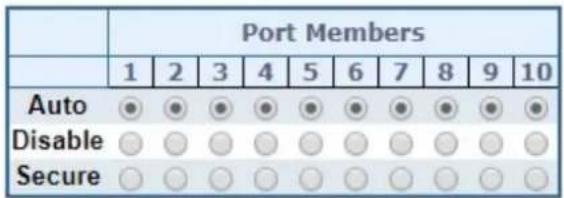
| Learning-disabled VLANs |
Static MAC Table Configuration
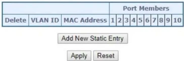
flowchart
graph TD
    A[" "] --> B["Port Members"]
    C["Delete"] --> D["VLAN ID"] --> E["MAC Address"] --> F["1"] --> G["2"] --> H["3"] --> I["4"] --> J["5"] --> K["6"] --> L["7"] --> M["8"] --> N["9"] --> O["10"]
    P["Add New Static Entry"] --> Q["Apply"] --> R["Reset"]
Figure 4-3-9-1: MAC Address Table Configuration Page Screenshot
The page includes the following fields:
Aging Configuration
By default, dynamic entries are removed from the MAC table after 300 seconds. This removal is also called aging.
| Object Description | |
| Disable Automatic Aging | Enables/disables the automatic aging of dynamic entries |
| Aging Time | The time after which a learned entry is discarded. By default, dynamic entries are removed from the MAC after 300 seconds. This removal is also called aging.(Range: 10-10000000 seconds; Default: 300 seconds) |
MAC Table Learning
If the learning mode for a given port is grayed out, another module is in control of the mode, so that it cannot be changed by the user. An example of such a module is the MAC-Based Authentication under 802.1X.
| Object Description | |
| • Auto | Learning is done automatically as soon as a frame with unknown SMAC is received. |
| • Disable | No learning is done. |
| • Secure | Only static MAC entries are learned, all other frames are dropped.Note: Make sure that the link used for managing the switch is added to the Static Mac Table before changing to secure learning mode, otherwise the management link is lost and can only be restored by using another non-secure port or by connecting to the switch via the serial interface. |
Static MAC Table Configuration
The static entries in the MAC table are shown in this table. The static MAC table can contain 64 entries. The MAC table is sorted first by VLAN ID and then by MAC address.
| Object Description | |
| Delete | Check to delete the entry. It will be deleted during the next save. |
| VLAN ID | The VLAN ID of the entry. |
| MAC Address | The MAC address of the entry. |
| Port Members | Checkmarks indicate which ports are members of the entry. Check or uncheck as needed to modify the entry. |
| Adding a New Static Entry | Click to add a new entry to the static MAC table.Specify the VLAN ID, MAC address, and port members for the new entry. Click "Save". |
Buttons
Apply
Click to apply changes
Reset
Click to undo any changes made locally and revert to previously saved values.
4.3.9.2 MAC Address Table Status
Dynamic MAC Table
Entries in the MAC Table are shown on this page. The MAC Table contains up to 8192 entries, and is sorted first by VLAN ID, then by MAC address. The MAC Address Table screen in Figure 4-3-9-2 appears.
MAC Address Table

Query by:
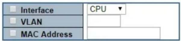
| Port Members | |||||||||||||
| Type | VLAN | MAC Address | CPU | 1 | 2 | 3 | 4 | 5 | 6 | 7 | 8 | 9 | 10 |
| Dynamic | 1 | 00-30-4F-9E-B7-DF | ✓ | ||||||||||
| Static | 1 | 01-00-5E-00-00-01 | ✓ | ✓ | ✓ | ✓ | ✓ | ✓ | ✓ | ✓ | ✓ | ✓ | ✓ |
| Static | 1 | 33-33-00-00-00-01 | ✓ | ✓ | ✓ | ✓ | ✓ | ✓ | ✓ | ✓ | ✓ | ✓ | ✓ |
| Static | 1 | 33-33-FF-11-22-34 | ✓ | ✓ | ✓ | ✓ | ✓ | ✓ | ✓ | ✓ | ✓ | ✓ | ✓ |
| Static | 1 | FF-FF-FF-FF-FF-FF | ✓ | ✓ | ✓ | ✓ | ✓ | ✓ | ✓ | ✓ | ✓ | ✓ | ✓ |
Figure 4-3-9-2: MAC Address Table Status Page Screenshot
Navigating the MAC Table
Each page shows up to 999 entries from the MAC table, default being 20, selected through the "entries per page" input field. When first visited, the web page will show the first 20 entries from the beginning of the MAC Table. The first displayed will be the one with the lowest VLAN ID and the lowest MAC address found in the MAC Table.
The "Start from MAC address" and "VLAN" input fields allow the user to select the starting point in the MAC Table. Clicking the "Refresh" button will update the displayed table starting from that or the closest next MAC Table match.
In addition, the two input fields will - upon a "Refresh" button click - assume the value of the first displayed entry, allowing for continuous refresh with the same start address.
The “>>” will use the last entry of the currently displayed VLAN/MAC address pairs as a basis for the next lookup. When the end is reached the text "no more entries" is shown in the displayed table. Use the "|<<" button to start over.
The page includes the following fields:
| Object Description | |
| • Type | Indicates whether the entry is a static or dynamic entry. |
| • VLAN | The VLAN ID of the entry. |
| • MAC Address | The MAC address of the entry. |
| • Port Members | The ports that are members of the entry. |
Buttons
Auto-refresh ☐: Automatic refresh occurs every 3 seconds.
Refreshes the displayed table starting from the "Start from MAC address" and "VLAN" input fields.
: Flushes all dynamic entries.

Updates the table starting from the first entry in the MAC Table, i.e. the entry with the lowest VLAN ID and MAC address.

Updates the table, starting with the entry after the last entry currently displayed.
4.3.10 Loop Protection
This chapter describes enabling loop protection function that provides loop protection to prevent broadcast loops in Managed Metro Switch.
4.3.10.1 Configuration
This page allows the user to inspect the current Loop Protection configurations, and possibly change them as well as screen in Figure 4-3-10-1 appears.
Loop Protection Configuration
General Settings
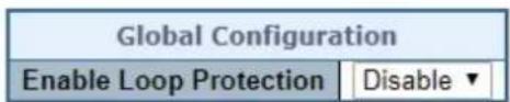
Port Configuration
| Port | Enable | Action | Tx Mode | |
| * | ✓ | |||
| 1 | Shutdown Port | ✓ | Disable ✓ | |
| 2 | Shutdown Port | ✓ | Disable ✓ | |
| 3 | Shutdown Port | ✓ | Disable ✓ | |
| 4 | Shutdown Port | ✓ | Disable ✓ | |
| 5 | Shutdown Port | ✓ | Disable ✓ | |
| 6 | Shutdown Port | ✓ | Disable ✓ | |
| 7 | Shutdown Port | ✓ | Disable ✓ | |
| 8 | Shutdown Port | ✓ | Disable ✓ | |
| 9 | Shutdown Port | ✓ | Disable ✓ | |
| 10 | Shutdown Port | ✓ | Disable ✓ | |
Apply Reset
Figure 4-3-10-1: Loop Protection Configuration Page Screenshot
The page includes the following fields:
General Settings
| Object Description | |
| • Enable Loop Protection | Controls whether loop protection is enabled (as a whole). |
Port Configuration
| Object Description | |
| • Port | The switch port number of the port. |
| • Enable | Controls whether loop protection is enabled on this switch port. |
| • Action | Configures the action performed when a loop is detected on a port. Valid values are Shutdown Port, Shutdown Port and Log or Log Only. |
| • Tx Mode | Controls whether the port is actively generating loop protection PDU's, or whether it is just passively looking for looped PDU's. |
Buttons
Apply
: Click to apply changes
Reset
Click to undo any changes made locally and revert to previously saved values.
4.3.10.2 Loop Protection Status
This page displays the loop protection port status of the switch; screen in Figure 4-3-10-2 appears.
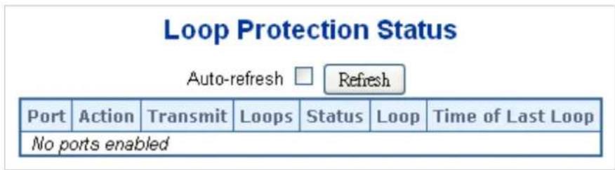
Figure 4-3-10-2: Loop Protection Status Screenshot
The page includes the following fields:
| Object Description | |
| • Port | The Managed Metro Switch port number of the logical port. |
| • Action | The currently configured port action. |
| • Transmit | The currently configured port transmit mode. |
| • Loops | The number of loops detected on this port. |
| • Status | The current loop protection status of the port. |
| • Loop | Whether a loop is currently detected on the port. |
| • Time of Last Loop | The time of the last loop event detected. |
Buttons
Auto-refresh ☐: Check this box to enable an automatic refresh of the page at regular intervals.
Refresh
Click to refresh the page immediately.
4.3.11 UDLD
Unidirectional Link Detection (UDLD) is a data link layer protocol from Cisco Systems to monitor the physical configuration of the cables and detect unidirectional links. UDLD complements the Spanning Tree Protocol which is used to eliminate switching loops..
4.3.11.1 UDLD Port Configuration
This page allows the user to inspect the current UDLDconfigurations, and possibly change them as well. as screen in Figure 4-3-11-1 appears.
UDLD Port Configuration
| Port | UDLD mode | Message Interval |
| * | 7 | |
| 1 | Disable▼ | 7 |
| 2 | Disable▼ | 7 |
| 3 | Disable▼ | 7 |
| 4 | Disable▼ | 7 |
| 5 | Disable▼ | 7 |
| 6 | Disable▼ | 7 |
| 7 | Disable▼ | 7 |
| 8 | Disable▼ | 7 |
| 9 | Disable▼ | 7 |
| 10 | Disable▼ | 7 |
Figure 4-3-11-1: UDLD Configuration Page Screenshot
The page includes the following fields:
General Settings
| Object Description | |
| • Port | Port number of the switch. |
| • UDLD Mode | Configures theUDLDMode on a port. Valid valuesareDisable, Normal and Aggressive. Default mode is Disable.Disable: In disabled mode, UDLD functionality doesn't exists on port..Normal: In normal mode, if the link state of the port was determined to be unidirectional, it will not affect the port state.Aggressive: In aggressive mode, unidirectional detected ports will get shutdown. To bring back the ports up, need to disableUDLDon that port |
| Message Interval | Configures the period of time between UDLD probe messages on ports that are in the advertisement phase and are determined to be bidirectional. The range is from 7 to 90 seconds(Default value is 7 seconds)(Currently default time interval is supported, due to lack of detailed information in RFC 5171). |
Buttons
Save
: Click to apply changes
Reset
Click to undo any changes made locally and revert to previously saved values.
4.3.11.2 UDLD Status
This page displays the UDLD status of the ports as well. as screen in Figure 4-3-11-2 appears.
Detailed UDLD Status for Port 1
Port 1

Auto-refresh

efresh
| UDLD status | |
| UDLD Admin state | Disable |
| Device ID(local) | A8-F7-F0-74-28-F1 |
| Device Name(local) | MGSD-10080F |
| Bidirectional State | Indeterminant |
Neighbour Status
| Port | Device Id | Link Status | Device Name |
| No Neighbour ports enabled or no existing partners | |||
Figure 4-3-11-2: UDLD status Page Screenshot
The page includes the following fields:
UDLD port status
| Object Description | |
| • UDLD Admin State | The current port state of the logical port, Enabled if any of state(Normal,Aggressive) is Enabled. |
| • Device ID(local) | The ID of Device. |
| • Device Name(local) | Name of the Device. |
| • Bidirectional State | The current state of the port. |
Neighbour Status
| Object Description | |
| • Port | The current port of neighbour device |
| • Device ID | The current ID of neighbour device. |
| • Link Status | The current link status of neighbour port. |
| • Device Name | Name of the Neighbour Device. |
Buttons
Auto-refresh ☐: Check this box to enable an automatic refresh of the page at regular intervals.
Refresh
Click to refresh the page immediately.
4.3.12 GVRP
GVRP (GARP VLAN Registration Protocol or Generic VLAN Registration Protocol) is a protocol that facilitates control of virtual local area networks (VLANs) within a larger network. It defines a way for switches to exchange VLAN information in order to register VLAN members on ports across the network.
GVRP - enabled Switches
VLAN Table
VLAN-1
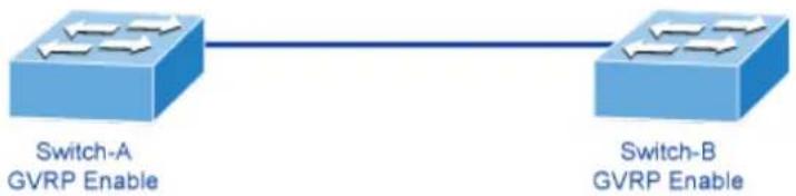
flowchart
graph LR
    A["Switch-A GVRP Enable"] --> B["Switch-B GVRP Enable"]
Switch-A – New VLAN ID Manually Added
VLAN Table
VLAN-1
VLAN-20
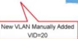

flowchart
graph LR
    A["Switch-A\nGVRP Enable"] -->|GVRP Joins packet\nVID=20| B["Switch-B\nGVRP Enable"]
    B --> C["VLAN Table\nVLAN-1"]
Switch-B Learning Dynamic VLAN from Switch-A
VLAN Table
VLAN-1
VLAN-20

flowchart
graph LR
    A["Switch-A\nGVRP Enable"] --> B["Switch-B\nGVRP Enable"]
    B --> C["VLAN Table\nVLAN-1\nVLAN-20 Dynamic"]
VLANs are dynamically configured based on join messages issued by host devices and propagated throughout the network. GVRP must be enabled to permit automatic VLAN registration, and to support VLANs which extend beyond the local switch.
4.3.12.1 GVRP Configuration
This page allows you to configure the global GVRP configuration settings that are commonly applied to all GVRP enabled ports. as well, as screen in Figure 4-3-12-1 appears.
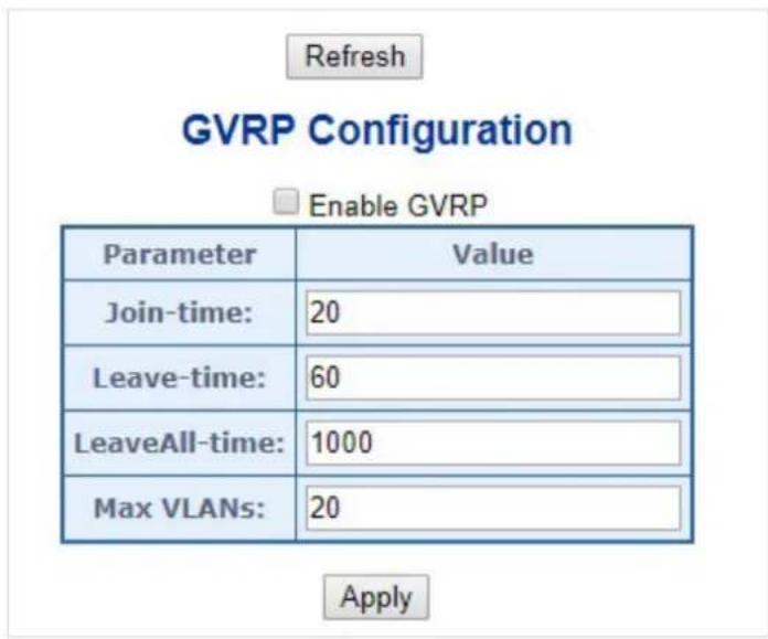
Figure 4-3-12-1: GVRP Configuration Page Screenshot
The page includes the following fields:
General Settings
| Object Description | |
| Enable GVRP globally | The GVRP feature is globally enabled by setting the check mark in the checkbox named Enable GVRP and pressing the Save button. |
| GVRP protocol timers | Join-time is a value in the range of 1-20cs, i.e. in units of one hundredth of a second. The default value is 20cs.Leave-time is a value in the range of 60-300cs, i.e. in units of one hundredth of a second. The default is 60cs.LeaveAll-time is a value in the range of 1000-5000cs, i.e. in units of one hundredth of a second. The default is 1000cs |
| Max number of VLANs | When GVRP is enabled, a maximum number of VLANs supported by GVRP is specified. By default this number is 20. This number can only be changed when GVRP is turned off. |
Buttons
Refresh
: Click to refresh the page. Note that unsaved changes will be lost.
Apply
: Click to apply changes
4.3.12.2 GVRP Port Configuration
This configuration can be performed either before or after GVRP is configured globally - the protocol operation will be the same. as well, as screen in Figure 4-3-12-2 appears.
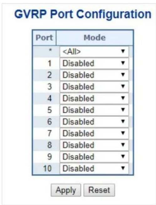
Figure 4-3-11-2: GVRP Port Configuration Page Screenshot
The page includes the following fields:
General Settings
| Object Description | |
| • Port | The logical port that is to be configured. |
| • Mode | Mode can be either 'Disabled' or 'GVRP enabled'. These values turn the GVRP feature off or on respectively for the port in question. |
Buttons

: Click to apply changes

: Click to undo any changes made locally and revert to previously saved values.
4.3.13 PTP
The Precision Time Protocol (PTP) is a protocol used to synchronize clocks throughout a computer network. On a local area network, it achieves clock accuracy in the sub-microsecond range, making it suitable for measurement and control systems.
Time Synchronization in Network
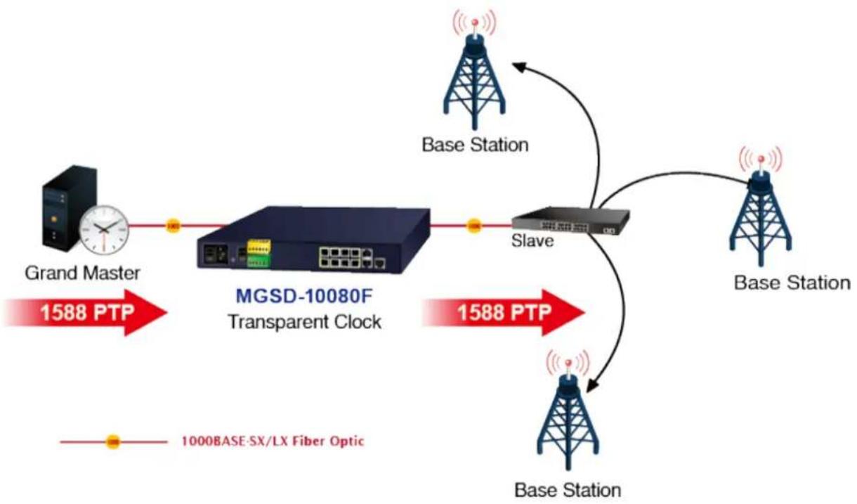
flowchart
graph TD
    A["Grand Master"] -->|1588 PTP| B["MGSD-10080F Transparent Clock"]
    B --> C["Slave"]
    C --> D["Base Station"]
    D --> E["Base Station"]
    E --> F["Base Station"]
    F --> G["1000BASE-SX/LX Fiber Optic"]
    style A fill:#f9f,stroke:#333
    style B fill:#ccf,stroke:#333
    style C fill:#cfc,stroke:#333
    style D fill:#fcc,stroke:#333
    style E fill:#cff,stroke:#333
    style F fill:#ffc,stroke:#333
    style G fill:#fcc,stroke:#333
PTP was originally defined in the IEEE 1588-2002 standard, officially entitled "Standard for a Precision Clock Synchronization Protocol for Networked Measurement and Control Systems" and published in 2002. In 2008 a revised standard, IEEE 588-2008 was released. This new version, also known as PTP Version 2, improves accuracy, precision and robustness but is not backwards compatible with the original 2002 version.
"IEEE 1588 is designed to fill a niche not well served by either of the two dominant protocols, NTP and GPS. IEEE 1588 is designed for local systems requiring accuracies beyond those attainable using NTP. It is also designed for applications that cannot bear the cost of a GPS receiver at each node, or for which GPS signals are inaccessible"
4.3.13.1 PTP Configuration
This page allows the user to configure and inspect the current PTP clock settings as screen in Figure 4-3-12-1 appears.
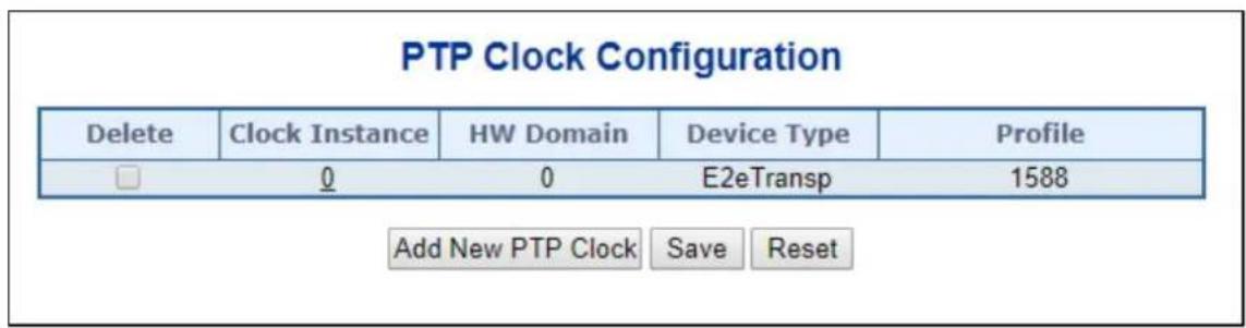
Figure 4-3-13-1: PTP Configuration Page Screenshot
| Object Description | |
| Delete | Check this box and click on 'Save' to delete the clock instance. |
| Clock Instance | Indicates the Instance of a particular Clock Instance [0..3].Click on the Clock Instance number to edit the Clock details |
| HW Domain | Indicates the HW clock domain used by the clock. |
| Device Type | Indicates the Type of the Clock Instance. There are five Device Types.P2p Transp - clock's Device Type is Peer to Peer Transparent Clock.E2e Transp - clock's Device Type is End to End Transparent Clock. |
| Profile | Indicates the profile used by the clock. |
Buttons
Click "Add New PTP Clock" to create a new clock instance
Click on the Clock Instance number to edit the Clock details
Save
: Click to apply changes
Reset
: Click to undo any changes made locally and revert to previously saved values.
PTP Clock's Configuration and Status
Clock Type and Profile
| Clock Instance | HW Domain | Device Type | Profile | Apply Profile Defaults | Filter Type |
| 0 | 0 | E2eTransp | 1588 | Apply | ACI_BASIC_PHASE_LOW▼ |
Port Enable and Configuration
| Port Enable | Configuration | |||||||||
| 1 | 2 | 3 | 4 | 5 | 6 | 7 | 8 | 9 | 10 | Ports Configuration |
Virtual Port Enable and Configuration
| Enable | I/O Pin | Class | Accuracy | Variance | Pri1 | Pri2 | Local Prio |
| False ▼ | 0 | 248 | 254 | 65535 | 128 | 128 | 128 |
Local Clock Current Time
| PTP Time | Clock Adjustment method | Synchronize to System Clock |
| 1970-01-01 Thu 03:41:03+00:00 806,497,060 | Internal Timer | Synchronize to System Clock |
Clock Current DataSet
| stpRm | Offset From Master | Mean Path Delay |
| 0 | 0.000,000,000 | 0.000,000,000 |
Clock Parent DataSet
| Parent Port ID | port | PStat | Var | Rate | GrandMaster ID | GrandMaster Clock Quality | Pri1 | Pri2 |
| a8:f7:00:ff:fe:00:12:34 | 0 | False | 0 | 0 | a8:f7:00:ff:fe:00:12:34 | Cl:248 Ac:Unknown Va:65535 | 128 | 128 |
Clock Default DataSet
| Device Type | One-Way | 2 Step Flag | Ports | Clock Identity | Dom | Clock Quality | |||||
| E2eTransp | False ▼ | False ▼ | 10 | a8:f7:00:ff:fe:00:12:34 | 0 | CI:248 Ac:Unknown Va:65535 | |||||
| Pri1 | Pri2 | Local Prio | Protocol | VID | PCP | DSCP | |||||
| 128 | 128 | 128 | Ethernet ▼ | 1 | 0 ▼ | 0 | |||||
Clock Time Properties DataSet
| UtcOffset | Valid | leap59 | leap61 | Time Trac | Freq Trac | ptp Time Scale | Time Source |
| 0 | False▼ | False▼ | False▼ | False▼ | False▼ | True▼ | 160 |
| Leap Pending | Leap Date | Leap Type | |||||
| False▼ | 1970-01-01 | leap61▼ | |||||
Apply Reset
The page includes the following fields:
Clock Type and Profile
Clock Type and Profile
| Clock Instance | HW Domain | Device Type | Profile | Apply Profile Defaults | Filter Type |
| 0 | 0 | E2eTransp | 1588 | Apply | ACI_BASIC_PHASE_LOW▼ |
| Object Description | ||||
| • Clock Instance | Indicates the instance number of a particular Clock Instance [0..3]. | |||
| • HW Domain | Indicates the HW clock domain used by the clock. | |||
| • Device Type | Indicates the Type of the Clock Instance. There are two Device Types. | |||
| ■ P2p Transp - clock's Device Type is Peer to Peer Transparent Clock.■ E2e Transp - clock's Device Type is End to End Transparent Clock. | ||||
| • Profile | Indicates the profile used by the clock. | |||
| • Apply Profile Defaults | If the clock has been configured to use a profile, clicking the 'Apply' button will reset configured values to profile defaults. | |||
| • Filter Type | The PTP filter type determines should match the operating conditions of the network and the PTP profile. | |||
| Filter Types | ||||
| PTP Profile | SyncE enabled(hybrid) | Filter type | Description | |
| 1588 | No | ACI_BASIC_PHASE | Requires PTP Sync and Delay_req frame rate of 16 fps or higher. | |
| 1588 | Yes | ACI_BASIC_PHASE_SYNCE | Requires PTP Sync and Delay_req frame rate of 16 fps or higher. | |
| 1588 | No | ACI_BASIC_PHASE_LOW | Use when the PTP Sync and Delay_req frame rate is between 1 fps to 16 fps. | |
| 1588 | Yes | ACI_BASIC_PHASE_LOW_SYNCE | Use when the PTP Sync and Delay_req frame rate is between 1 fps to 16 fps. | |
| None | No | ACI_BC_FULL_ON_PATH_FREQ | Used for Syntonized TC with basic filter. | |
Port Enable and Configuration
Port Enable and Configuration
| Port Enable | Configuration | |||||||||
| 1 | 2 | 3 | 4 | 5 | 6 | 7 | 8 | 9 | 10 | Ports Configuration |
| Object Description | |
| • Port Enable | Set check mark for each port configured for this Clock Instance. |
| • Configuration | Click 'Ports Configuration' to edit the port data set for the ports assigned to this clock instance. |
The port data set is defined in the IEEE 1588 Standard. It holds three groups of data: the static members, the dynamic members, and configurable members which can be set here.
PTP Clock's Port Data Set Configuration
| Port | Stat | MDR | PeerMeanPathDel | Anv | ATo | Syv | Dlm | MPR | Delay Asymmetry | Ingress Latency | Egress Latency | Version | Mcast Addr | Not Slave | Local Prio | 2 Step Flag |
| 1 | dsbl | 0 | 0.000,000,000 | 1 | 3 | 0 | e2e ▼ | 0 | 0 | 0 | 0 | 2 | Default ▼ | False ▼ | 128 | Clock Def. ▼ |
| 2 | dsbl | 0 | 0.000,000,000 | 1 | 3 | 0 | e2e ▼ | 0 | 0 | 0 | 0 | 2 | Default ▼ | False ▼ | 128 | Clock Def. ▼ |
Apply Reset
Port Data Set
| Object Description | |
| • Port | Static member port Identity: Port number [1..max port no] |
| • Stat | Dynamic member portState: Current state of the port. |
| • MDR | Dynamic member log Min Delay Req Interval: The delay request interval announced by the master. |
| • Peer Mean Path Del | The path delay measured by the port in P2P mode. In E2E mode this value is 0 |
| • Anv | The interval for issuing announce messages in master state. Range is -3 to 4. |
| • ATo | The timeout for receiving announce messages on the port. Range is 1 to 10. |
| • Syv | The interval for issuing sync messages in master. Range is -7 to 4. |
| • Dlm | Configurable member delayMechanism:The delay mechanism used for the port:e2e End to end delay measurementp2p Peer to peer delay measurement.Can be defined per port in an Ordinary/Boundary clock.In a transparent clock all ports use the same delay mechanism, determined by the clock type. |
| • MPR | The interval for issuing Delay_Req messages for the port in E2e mode.This value is announced from the master to the slave in an announce message.The value is reflected in the MDR field in the SlaveThe interval for issuing Pdelay_Req messages for the port in P2P modeRange is -7 to 5.Note:The interpretation of this parameter has changed from release 2.40. In earlier versions the value was interpreted relative to the Sync interval, this was a violation of the standard, so now the value is interpreted as an interval. I.e.MPR=0 => 1 Delay_Req pr sec, independent of the Sync rate. |
| • Delay Asymmetry | If the transmission delay for a link in not symmetric, the asymmetry can be configured here, see IEEE 1588 Section 7.4.2 Communication path asymmetryRange is -100000 to 100000.VersionThe current implementation only supports PTP version 2 |
| • Ingress latency | Ingress latency measured in ns, as defined in IEEE 1588 Section 7.3.4.2.Range is -100000 to 100000. |
| • Egress Latency | Egress latency measured in ns, as defined in IEEE 1588 Section 7.3.4.2.Range is -100000 to 100000. |
| • Version | PTP version used by this port |
| • Mcast Addr | Configured destination address for multicast packets (PTP default or LinkLocal) |
| • Not Slave | TRUE indicates that this interface cannot enter slave mode |
| • Local Prio | 1-255, priority used in the 8275.1 BMCA |
| • 2 Step Flag | Option to override the 2-step option on port level */ // IEEE 802.1AS specific parameters are only available when the 802.1AS profile is selected |
Virtual Port Enable and Configuration
Virtual Port Enable and Configuration
| Enable | I/O Pin | Class | Accuracy | Variance | Pri1 | Pri2 | Local Prio |
| False ▼ | 0 | 248 | 254 | 65535 | 128 | 128 | 128 |
| Object Description | |
| Enable | Disabled or Enabled. |
| I/O Pin | Virtual Port I/O Pin. The valid range is 0 to 3. |
| Class | Clock class value for clock as defined in IEEE Std 1588. The valid range is from 0 to 255. |
| Accuracy | Clock accuracy value as defined in IEEE Std 1588. The valid range is 0 to 255. |
| Variance | offsetScaledLogVariance for clock as defined in IEEE Std 1588. The valid range is 0 to 65535. |
| Pri1 | Clock priority 1 [0..255] used by the BMC master select algorithm. |
| Pri2 | Clock priority 2 [0..255] used by the BMC master select algorithm. |
| Local Prio | Priority [1..255]used in the 8275.1 BMCA. |
Local Clock Current Time
Local Clock Current Time
| PTP Time | Clock Adjustment method | Synchronize to System Clock |
| 1970-01-01 Thu 03:41:03+00:00 806,497,060 | Internal Timer | Synchronize to System Clock |
| Object Description | |
| PTP Time | Shows the actual PTP time with nanosecond resolution. |
| Clock Adjustment Method | Shows the actual clock adjustment method. The method depends on the available hardware. |
| Synchronize to System Clock | Activate this button to synchronize the System Clock to PTP Time. |
Clock current Data Set
Clock Current DataSet
| stpRm | Offset From Master | Mean Path Delay |
| 0 | 0.000,000,000 | 0.000,000,000 |
| Object Description | |
| • stpRm | Steps Removed : It is the number of PTP clocks traversed from the grandmaster to the local slave clock. |
| Offset from master | Time difference between the master clock and the local slave clock, measured in ns. |
| Mean Path Delay | The mean propagation time for the link between the master and the local slave |
Clock Parent Data Set
The clock parent data set is defined in the IEEE 1588 standard. The parent data set is dynamic.
Clock Parent DataSet
| Parent Port ID | port | PStat | Var | Rate | GrandMaster ID | GrandMaster Clock Quality | Pri1 | Pri2 |
| a8:f7:00:ff:fe:00:12:34 | 0 | False | 0 | 0 | a8:f7:00:ff:fe:00:12:34 | CI:248 Ac:Unknown Va:65535 | 128 | 128 |
| Object Description | |
| • Parent Port Identity | Clock identity for the parent clock, if the local clock is not a slave, the value is the clocks own id. |
| • Port | Port Id for the parent master port |
| • P Stat | Parents Stats (always false). |
| • Var | It is observed parent offset scaled log variance |
| • Rate | Observed Parent Clock Phase Change Rate. i.e. the slave clocks rate offset compared to the master. (unit = ns per s). |
| • Grand Master ID | Clock identity for the grand master clock, if the local clock is not a slave, the value is the clocks own id. |
| • Grand Master Clock Quality | The clock quality announced by the grand master (See description of Clock Default Data Set: Clock Quality) |
| • Pri1 | Clock priority 1 announced by the grand master |
| • Pri2 | Clock priority 2 announced by the grand master |
Clock Default Data Set
The clock default data set is defined in the IEEE 1588 Standard. It holds three groups of data: the static members defined at clock creation time, the Dynamic members defined by the system, and the configurable members which can be set here.
Clock Default DataSet
| Device Type | One-Way | 2 Step Flag | Ports | Clock Identity | Dom | Clock Quality | |||||
| E2eTransp | False ▼ | False ▼ | 10 | a8:f7:00:ff:fe:00:12:34 | 0 | CI:248 Ac:Unknown Va:65535 | |||||
| Pri1 | Pri2 | Local Prio | Protocol | VID | PCP | DSCP | |||||
| 128 | 128 | 128 | Ethernet ▼ | 1 | 0 ▼ | 0 | |||||
| Object Description | |
| • Device Type | Indicates the Type of the Clock Instance. There are five Device Types.P2p Transp - clock's Device Type is Peer to Peer Transparent Clock.E2e Transp - clock's Device Type is End to End Transparent Clock. |
| One-Way | If true, one way measurements are used.This parameter applies only to a slave. In one-way mode no delay measurements are performed, i.e. this is applicable only if frequency synchronization is needed.The master always responds to delay requests. |
| 2 Step Flag | Static member: defined by the system, true if two-step Sync events and Pdelay_Resp events are used |
| Ports | The total number of physical ports in the node |
| Clock Identity | It shows unique clock identifier |
| Dom | Clock domain [0..127]. |
| Clock Quality | The clock quality is determined by the system, and holds 3 parts: Clock Class,Clock Accuracy and OffsetScaledLog Variance as defined in IEEE1588.The Clock Accuracy values are defined in IEEE1588 table 6 (Currently the clock Accuracy is set to 'Unknown' as default). |
| Pri1 | Clock priority 1 [0..255] used by the BMC master select algorithm. |
| Pri2 | Clock priority 2 [0..255] used by the BMC master select algorithm. |
| Local Prio | Priority [1..255] used in the 8275.1 BMCA. |
| Protocol | Transport protocol used by the PTP protocol engine■ Ethernet PTP over Ethernet multicast■ EthernetMixed PTP using a combination of Ethernet multicast and unicast■ IPv4Multi PTP over IPv4 multicast■ IPv4Mixed PTP using a combination of IPv4 multicast and unicast■ IPv4Uni PTP over IPv4 unicast |
| VID | VLAN Identifier used for tagging the VLAN packets. |
| PCP | Priority Code Point value used for PTP frames. |
| DSCP | DSCP value used when transmitting IPv4 encapsulated packets |
Clock Time Properties Data Set
The clock time properties data set is defined in the IEEE 1588 Standard. The data set is both configurable and dynamic, i.e. the parameters can be configured for a grandmaster. In a slave clock the parameters are overwritten by the grandmasters timing properties. The parameters are not used in the current PTP implementation.
The valid values for the Time Source parameter are:
■ 16 (0x10) ATOMIC_CLOCK
■ 32 (0x20) GPS
■ 48 (0x30) TERRESTRIAL_RADIO
64 (0x40) PTP
■ 80 (0x50) NTP
■ 96 (0x60) HAND_SET
144 (0x90) OTHER
■ 160 (0xA0) INTERNAL_OSCILLATOR
Clock Time Properties DataSet
| UtcOffset | Valid | leap59 | leap61 | Time Trac | Freq Trac | ptp Time Scale | Time Source |
| 0 | False▼ | False▼ | False▼ | False▼ | False▼ | True▼ | 160 |
| Leap Pending | Leap Date | Leap Type | |||||
| False▼ | 1970-01-01 | leap61▼ | |||||
| Object Description | |
| • UtcOffset | In systems whose epoch is UTC, it is the offset between TAI and UTC |
| • Valid | When true, the value of currentUtcOffset is valid |
| • leap59 | When true, this field indicates that last minute of the current UTC day has only 59 seconds. |
| • leap61 | When true, this field indicates that last minute of the current UTC day has 61 seconds. |
| • Time Trac | True if the timescale and the value of currentUtcOffset are traceable to a primary reference. |
| • Freq Trac | True if the frequency determining the timescale is traceable to a primary reference. |
| • ptp Time Scale | True if the clock timescale of the grandmaster clock and false otherwise. |
| • Time Source | The source of time used by the grandmaster clock. |
| • Leap Pending | When true, there is a leap event pending at the date defined by leapDate. |
| • Leap Date | The date for which the leap will occur at the end of its last minute.Date is represented as the number of days after 1970-01-01 (the latter represented as 0). |
| • Leap Type | The type of leap event i.e. leap59 or leap61. |
4.3.14 Link OAM
4.3.14.1 Statistics
This page provides detailed OAM traffic statistics for a specific switch port. Use the port select box to select which switch port details to display. The displayed counters represent the total number of OAM frames received and transmitted for the selected port. Discontinuities of these counter can occur at re-initialization of the management system. as screen in Figure 4-3-14-1 appears.
| Receive Total | Transmit Total |
| Rx OAM Information PDU's 0 | Tx OAM Information PDU's 0 |
| Rx Unique Error Event Notification 0 | Tx Unique Error Event Notification 0 |
| Rx Duplicate Error Event Notification 0 | Tx Duplicate Error Event Notification 0 |
| Rx Loopback Control 0 | Tx Loopback Control 0 |
| Rx Variable Request 0 | Tx Variable Request 0 |
| Rx Variable Response 0 | Tx Variable Response 0 |
| Rx Org Specific PDU's 0 | Tx Org Specific PDU's 0 |
| Rx Unsupported Codes 0 | Tx Unsupported Codes 0 |
| Rx Link Fault PDU's 0 | Tx Link Fault PDU's 0 |
| Rx Dying Gasp 0 | Tx Dying Gasp 0 |
| Rx Critical Event PDU's 0 | Tx Critical Event PDU's 0 |
Figure 4-3-14-1: Link OAM Statistic Page Screenshot
The page includes the following fields:
General Settings
| Object Description | |
| Rx and Tx OAM Information PDU's | The number of received and transmitted OAM Information PDU's. Discontinuities of this counter can occur at re-initialization of the management system. |
| Rx and Tx Unique Error Event Notification | A count of the number of unique Event OAMPDUs received and transmitted on this interface. Event Notifications may be sent in duplicate to increase the probability of successfully being received, given the possibility that a frame may be lost in transit. Duplicate Event Notification transmissions are counted by Duplicate Event Notification counters for Tx and Rx respectively.A unique Event Notification OAMPDU is indicated as an Event Notification OAMPDU with a Sequence Number field that is distinct from the previously transmitted Event Notification OAMPDU Sequence Number. |
| Rx and Tx Duplicate Error Event Notification | A count of the number of duplicate Event OAMPDUs received and transmitted on this interface. Event Notification OAMPDUs may be sent in duplicate to increase the probability of successfully being received, given the possibility that a frame may be lost in transit.A duplicate Event Notification OAMPDU is indicated as an Event Notification |
| OAMPDU with a Sequence Number field that is identical to the previously transmitted Event Notification OAMPDU Sequence Number. | |
| Rx and Tx Loopback Control | A count of the number of Loopback Control OAMPDUs received and transmitted on this interface. |
| Rx and Tx Variable Request | A count of the number of Variable Request OAMPDUs received and transmitted on this interface. |
| Rx and Tx Variable Response | A count of the number of Variable Response OAMPDUs received and transmitted on this interface. |
| Rx and Tx Org Specific PDU's | A count of the number of Organization Specific OAMPDUs transmitted on this interface. |
| Rx and Tx Unsupported Codes | A count of the number of OAMPDUs transmitted on this interface with an unsupported op-code. |
| Rx and Tx Link fault PDU's | A count of the number of Link fault PDU's received and transmitted on this interface. |
| Rx and Tx Dying Gasp | A count of the number of Dying Gasp events received and transmitted on this interface. |
| Rx and Tx Critical Event PDU's | A count of the number of Critical event PDU's received and transmitted on this interface. |
Buttons
Auto-refresh ☐: Automatic refresh occurs every 3 seconds.
Refresh
Click to refresh the page immediately.
Clear
: Clears the counters for the selected port.
4.3.14.2 Port Status
This page provides Link OAM configuration operational status. The displayed fields shows the active configuration status for the selected port. as well. as screen in Figure 4-3-14-2 appears.
Detailed Link OAM Status for Port 1
| Port 1 Auto-refresh Refresh | |
| PDU Permission | Receive only |
| Discovery State | Fault state |
| Peer MAC Address | ---- |
| Local | Peer | ||
| Mode | Passive | Mode | ---- |
| Unidirectional Operation Support | Disabled | Unidirectional Operation Support | ---- |
| Remote Loopback Support | Disabled | Remote Loopback Support | ---- |
| Link Monitoring Support | Enabled | Link Monitoring Support | ---- |
| MIB Retrieval Support | Disabled | MIB Retrieval Support | ---- |
| MTU Size | 1500 | MTU Size | ---- |
| Multiplexer State | Forwarding | Multiplexer State | ---- |
| Parser State | Forwarding | Parser State | ---- |
| Organizational Unique Identification | a8-f7-e0 | Organizational Unique Identification | ---- |
| PDU Revision | 0 | PDU Revision | ---- |
Figure 4-3-14-2: Port Status Page Screenshot
The page includes the following fields:
General Settings
| Object Description | |
| PDU Permission | This field is available only for the Local DTE.It displays the current permission rules set for the local DTE. Possible values are■ Link fault■ Receive only■ Information exchange only■ ANY |
| Discovery State | Displays the current state of the discovery process.Possible states are■ Fault state■ Active state■ Passive state■ SEND_LOCAL_REMOTE_STATE■ SEND_LOCAL_REMOTE_OK_STATE■ SEND_ANY_STATE |
| Mode | The Mode in which the Link OAM is operating, Active or Passive. |
| UnidirectionalOperation Support | This feature is not available to be configured by the user. The status of this configuration is retrieved from the PHY. |
| • Remote Loopback Support | If status is enabled, DTE is capable of OAM remote loopback mode. |
| • Link Monitoring Support | If status is enabled, DTE supports interpreting Link Events. |
| • MIB Retrieval Support | If status ie enabled DTE supports sending Variable Response OAMPDUs. |
| • MTU Size | It represents the largest OAMPDU, in octets, supported by the DTE.This value is compared to the remotes Maximum PDU Size and the smaller of the two is used. |
| • Multiplexer State | When in forwarding state, the Device is forwarding non-OAMPDUs to the lower sublayer. Incase of discarding, the device discards all the non-OAMPDU's. |
| • Parser State | When in forwarding state, Device is forwarding non-OAMPDUs to higher sublayer.When in loopback, Device is looping back non-OAMPDUs to the lower sublayer.When in discarding state, Device is discarding non-OAMPDUs. |
| • Organizational Unique Identification | 24-bit Organizationally Unique Identifier of the vendor. |
| • PDU Revision | It indicates the current revision of the Information TLV.The value of this field shall start at zero and be incremented each time something in the Information TLV changes. Upon reception of an Information TLV from a peer, an OAM client may use this field to decide if it needs to be processed (an Information TLV that is identical to the previous Information TLV doesn't need to be parsed as nothing in it has changed). |
Buttons
Auto-refresh ☐: Check this box to enable an automatic refresh. Automatic refresh occurs every 3 seconds.
Refresh
Click to refresh the page immediately.
4.3.14.3 Event Status
This page allows the user to inspect the current Link OAM Link Event configurations, and change them as well. as screen in Figure 4-3-14-3 appears.
| Detailed Link OAM Link Status for Port 1 Port 1 Auto-refresh Refresh | |
| Local Frame Error Status | Remote Frame Error Status |
| Sequence Number 0 Frame Error Event Timestamp 0 Frame error event window 0 Frame error event threshold 0 Frame errors 0 Total frame errors 0 Total frame error events 0 | Frame Error Event Timestamp 0 Frame error event window 0 Frame error event threshold 0 Frame errors 0 Total frame errors 0 Total frame error events 0 |
| Local Frame Period Status | Remote Frame Period Status |
| Frame Period Error Event Timestamp 0 Frame Period Error Event Window 0 Frame Period Error Event Threshold 0 Frame Period Errors 0 Total frame period errors 0 Total frame period error events 0 | Frame Period Error Event Timestamp 0 Frame Period Error Event Window 0 Frame Period Error Event Threshold 0 Frame Period Errors 0 Total frame period errors 0 Total frame period error events 0 |
| Local Symbol Period Status | Remote Symbol Period Status |
| Symbol Period Error Event Timestamp 0 Symbol Period Error Event Window 0 Symbol Period Error Event Threshold 0 Symbol Period Errors 0 Total symbol period errors 0 Total Symbol period error events 0 | Symbol Period Error Event Timestamp 0 Symbol Period Error Event Window 0 Symbol Period Error Event Threshold 0 Symbol Period Errors 0 Total symbol period errors 0 Total Symbol period error events 0 |
| Local Event Seconds Summary Status | Remote Event Seconds Summary Status |
| Error Frame Seconds Summary Event Timestamp 0 Error Frame Seconds Summary Event window 0 Error Frame Seconds Summary Event Threshold 0 Error Frame Seconds Summary Errors 0 Total Error Frame Seconds Summary Errors 0 Total Error Frame Seconds Summary Events 0 | Error Frame Seconds Summary Event Timestamp 0 Error Frame Seconds Summary Event window 0 Error Frame Seconds Summary Event Threshold 0 Error Frame Seconds Summary Errors 0 Total Error Frame Seconds Summary Errors 0 Total Error Frame Seconds Summary Events 0 |
Figure 4-3-14-3: Link OAM Statistic Page Screenshot
The page includes the following fields:
General Settings
| Object Description | |
| • Port | The switch port number. |
| • Sequence Number | This two-octet field indicates the total number of events occurred at the remote end. |
| • Frame Error Event Timestamp | This two-octet field indicates the time reference when the event was generated, in terms of 100 ms intervals. |
| • Frame error event window | This two-octet field indicates the duration of the period in terms of 100 ms intervals. 1) The default value is one second. 2) The lower bound is one second. 3) The upper bound is one minute. |
| • Frame error event threshold | This four-octet field indicates the number of detected errored frames in the period is required to be equal to or greater than in order for the event to be generated. 1) The default value is one frame error. 2) The lower bound is zero frame errors. 3) The upper bound is unspecified. |
| Frame errors | This four-octet field indicates the number of detected errored frames in the period. |
| Total frame errors | This eight-octet field indicates the sum of errored frames that have been detected since the OAM sublayer was reset. |
| Total frame error events | This four-octet field indicates the number of Errored Frame Event TLVs that have been generated since the OAM sublayer was reset. |
| Frame Period Error Event Timestamp | This two-octet field indicates the time reference when the event was generated, in terms of 100 ms intervals. |
| Frame Period Error Event Window | This four-octet field indicates the duration of period in terms of frames. |
| Frame Period Error Event Threshold | This four-octet field indicates the number of errored frames in the period is required to be equal to or greater than in order for the event to be generated. |
| Frame Period Errors | This four-octet field indicates the number of frame errors in the period. |
| Total frame period errors | This eight-octet field indicates the sum of frame errors that have been detected since the OAM sublayer was reset. |
| Total frame period error events | This four-octet field indicates the number of Errored Frame Period Event TLVs that have been generated since the OAM sublayer was reset |
| Symbol Period Error Event Timestamp | This two-octet field indicates the time reference when the event was generated, in terms of 100 ms intervals. |
| Symbol Period Error Event Window | This eight-octet field indicates the number of symbols in the period. |
| Symbol Period Error Event Threshold | This eight-octet field indicates the number of errored symbols in the period is required to be equal to or greater than in order for the event to be generated. |
| Symbol Period Errors | This eight-octet field indicates the number of symbol errors in the period. |
| Total symbol period errors | This eight-octet field indicates the sum of symbol errors since the OAM sublayer was reset. |
| Total Symbol period error events | This four-octet field indicates the number of Errored Symbol Period Event TLVs that have been generated since the OAM sublayer was reset. |
| Error Frame Seconds Summary Event Timestamp | This two-octet field indicates the time reference when the event was generated, in terms of 100 ms intervals, encoded as a 16-bit unsigned integer. |
| Error Frame Seconds Summary Event window | This two-octet field indicates the duration of the period in terms of 100 ms intervals, encoded as a 16-bit unsigned integer. |
| Error Frame Seconds Summary Event Threshold | This two-octet field indicates the number of errored frame seconds in the period is required to be equal to or greater than in order for the event to be generated, encoded as a 16-bit unsigned integer. |
| Error Frame Seconds Summary Errors | This two-octet field indicates the number of errored frame seconds in the period, encoded as a 16-bit unsigned integer. |
| • Total Error FrameSeconds SummaryErrors | This four-octet field indicates the sum of errored frame seconds that have been detected since the OAM sublayer was reset. |
| • Total Error FrameSeconds SummaryEvents | This four-octet field indicates the number of Errored Frame Seconds Summary Event TLVs that have been generated since the OAM sublayer was reset, encoded as a 32bit unsigned integer. |
Buttons
Auto-refresh ☐: Check this box to enable an automatic refresh. Automatic refresh occurs every 3 seconds.
Refresh
Click to refresh the page immediately.
4.3.14.4 Port Settings
This page allows the user to inspect the current Link OAM port configurations, and change them as well, as screen in Figure 4-3-14-4 appears.
Link OAM Port Configuration
| Port | OAM Enabled | OAM Mode | Loopback Support | Link Monitor Support | MIB Retrieval Support | Loopback Operation |
| * | □ | □ | □ | □ | □ | |
| 1 | □ | Passive | □ | ✓ | □ | □ |
| 2 | □ | Passive | □ | ✓ | □ | □ |
| 3 | □ | Passive | □ | ✓ | □ | □ |
| 4 | □ | Passive | □ | ✓ | □ | □ |
| 5 | □ | Passive | □ | ✓ | □ | □ |
| 6 | □ | Passive | □ | ✓ | □ | □ |
| 7 | □ | Passive | □ | ✓ | □ | □ |
| 8 | □ | Passive | □ | ✓ | □ | □ |
| 9 | □ | Passive | □ | ✓ | □ | □ |
| 10 | □ | Passive | □ | ✓ | □ | □ |
Figure 4-3-14-4: Port Status Page Screenshot
The page includes the following fields:
General Settings
| Object Description | |
| • Port | The switch port number. |
| • OAM Enabled | Controls whether Link OAM is enabled on this switch port. Enabling Link OAM provides the network operators the ability to monitor the health of the network and quickly determine the location of failing links or fault conditions. |
| • OAM Mode | Configures the OAM Mode as Active or Passive. The default mode is Passive.■ Active modeDTE's configured in Active mode initiate the exchange of InformationOAMPDUs as defined by the Discovery process. Once the Discovery process completes, Active DTE's are permitted to send any OAMPDU while connected to a remote OAM peer entity in Active mode. Active DTE's operate in a limited respect if the remote OAM entity is operating in Passive mode. Active devices should not respond to OAM remote loopback commands and variable requests from a Passive peer.■ Passive modeDTE's configured in Passive mode do not initiate the Discovery process.Passive DTE's react to the initiation of the Discovery process by the remote DTE. This eliminates the possibility of passive to passive links. Passive DTE's shall not send Variable Request or Loopback Control OAMPDUs. |
| • Loopback Support | Controls whether the loopback support is enabled for the switch port. Link OAM remote loopback can be used for fault localization and link performance testing.Enabling the loopback support will allow the DTE to execute the remote loopback command that helps in the fault detection. |
| • Link Monitor Support | Controls whether the Link Monitor support is enabled for the switch port. On enabling the Link Monitor support, the DTE supports event notification that permits the inclusion of diagnostic information. |
| • MIB Retrieval Support | Controls whether the MIB Retrieval Support is enabled for the switch port. On enabling the MIB retrieval support, the DTE supports polling of various Link OAM based MIB variables' contents. |
| • Loopback Operation | If the Loopback support is enabled, enabling this field will start a loopback operation for the port. |
Buttons
Save
: Click to apply changes
Reset
Click to undo any changes made locally and revert to previously saved values.
4.3.14.5 Event Settings
This page allows the user to inspect the current Link OAM Link Event configurations, and change them as well, as screen in Figure 4-3-14-5 appears.
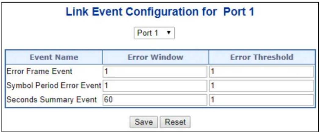
Figure 4-3-14-5: Event Settings Page Screenshot
The page includes the following fields:
General Settings
| Object | Description |
| • Port | The switch port number. |
| • Event Name | Name of the Link Event which is being configured. |
| • Error Window | Represents the window period in the order of 1 sec for the observation of various link events. |
| • Error Threshold | Represents the threshold value for the window period for the appropriate Link event so as to notify the peer of this error. |
| • Error Frame Event | The Errored Frame Event counts the number of errored frames detected during the specified period. The period is specified by a time interval (Window in order of 1 sec). This event is generated if the errored frame count is equal to or greater than the specified threshold for that period (Period Threshold). Errored frames are frames that had transmission errors as detected at the Media Access Control sublayer. Error Window for 'Error Frame Event' must be an integer value between 1-60 and its default value is '1'. Whereas Error Threshold must be between 0-4294967295 and its default value is '1'. |
| • Symbol Period Error Event | ved in a time interval on the underlying physical layer. This event is generated if the symbol error count is equal to or greater than the specified threshold for that period. Error Window for 'Symbol Period Error Event' must be an integer value between 1-60 and its default value is '1'. Whereas Error Threshold must be between 0-4294967295 and its default value is '1'. |
| • Seconds Summary Event | The Errored Frame Seconds Summary Event TLV counts the number of errored frame seconds that occurred during the specified period. The period is specifiedby a time interval. This event is generated if the number of errored frame seconds is equal to or greater than the specified threshold for that period. An errored frame second is a one second interval wherein at least one frame error was detected. Errored frames are frames that had transmission errors as detected at the Media Access Control sublayer. Error Window for 'Seconds Summary Event' must be an integer value between 10-900 and its default value is '60'. Whereas Error Threshold must be between 0-65535 and its default value is '1'. |
Buttons
Save
: Click to apply changes
Reset
Click to undo any changes made locally and revert to previously saved values.
4.3.14.6 MIB Retrieval
This page allows you to configure Link OAM MIB Retrieval, as screen in Figure 4-3-14-6 appears.
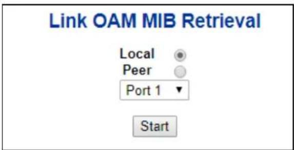
Figure 4-3-14-6: MIB Retrieval Page Screenshot
4.3.14.7 Link-OAM Example
CE and PE devices with point-to-point link enable EFM OAM to monitor "the First Mile" link performance. It will report the log information to network management system when occurring fault event and use remote loopback function to detect the link in necessary instance
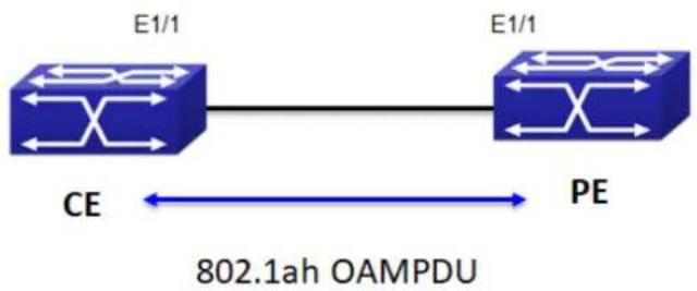
flowchart
graph LR
    A["E1/1"] --> B["802.1ah OAMPDU"]
    C["CE"] <--> D["PE"]
    style A fill:#4CAF50,stroke:#333
    style B fill:#4CAF50,stroke:#333
    style C fill:#4CAF50,stroke:#333
Figure 4-3-14-7: Typical OAM application topology
The configuration of link-oam is quite simple.
Step 1. Set CE as Passive OAM mode
Link OAM Port Configuration
| Port | OAM Enabled | OAM Mode | Loopback Support | Link Monitor Support | MIB Retrieval Support | Loopback Operation |
| * | □ | <All> ▼ | □ | □ | □ | □ |
| 1 | ☑ | Passive ▼ | □ | ☑ | □ | □ |
Step 2. Set PE as Active OAM mode
Link OAM Port Configuration
| Port | OAM Enabled | OAM Mode | Loopback Support | Link Monitor Support | MIB Retrieval Support | Loopback Operation |
| * | □ | <All> ▼ | □ | □ | □ | □ |
| 1 | ☑ | Active ▼ | □ | ☑ | □ | □ |
Step 3. Check OAM status and statistic from CE device
Detailed Link OAM Status for Port 1
| Port 1 | Auto-refresh | Refresh |
| PDU Permission | Any | |
| Discovery State | SEND_ANY_STATE | |
| Peer MAC Address | 00:30:4f:11:22:55 |
| Local | Peer | ||
| Mode | Passive | Mode | Active |
| Unidirectional Operation Support | Disabled | Unidirectional Operation Support | Disabled |
| Remote Loopback Support | Disabled | Remote Loopback Support | Disabled |
| Link Monitoring Support | Enabled | Link Monitoring Support | Enabled |
| MIB Retrieval Support | Disabled | MIB Retrieval Support | Disabled |
| MTU Size | 1500 | MTU Size | 1500 |
| Multiplexer State | Forwarding | Multiplexer State | Forwarding |
| Parser State | Forwarding | Parser State | Forwarding |
| Organizational Unique Identification | 00-30-4f | Organizational Unique Identification | 00-30-4f |
| PDU Revision | 1 | PDU Revision | 0 |
Detailed Link OAM Statistics for Port 1
| Receive Total | Transmit Total | ||
| Rx OAM Information PDU's | 232 | Tx OAM Information PDU's | 232 |
4.4 Quality of Service
4.4.1 General
Quality of Service (QoS) is an advanced traffic prioritization feature that allows you to establish control over network traffic. QoS enables you to assign various grades of network service to different types of traffic, such as multi-media, video, protocol-specific, time critical, and file-backup traffic.
QoS reduces bandwidth limitations, delay, loss, and jitter. It also provides increased reliability for delivery of your data and allows you to prioritize certain applications across your network. You can define exactly how you want the switch to treat selected applications and types of traffic. You can use QoS on your system to:
• Control a wide variety of network traffic by:
• Classifying traffic based on packet attributes.
- Assigning priorities to traffic (for example, to set higher priorities to time-critical or business-critical applications).
- Applying security policy through traffic filtering.
- Provide predictable throughput for multimedia applications such as video conferencing or voice over IP by minimizing delay and jitter.
- Improve performance for specific types of traffic and preserve performance as the amount of traffic grows.
- Reduce the need to constantly add bandwidth to the network.
- Manage network congestion.
QoS Terminology
- Classifier—classifies the traffic on the network. Traffic classifications are determined by protocol, application, source, destination, and so on. You can create and modify classifications. The Switch then groups classified traffic in order to schedule them with the appropriate service level.
- DiffServ Code Point (DSCP) — is the traffic prioritization bits within an IP header that are encoded by certain applications and/or devices to indicate the level of service required by the packet across a network.
- Service Level—defines the priority that will be given to a set of classified traffic. You can create and modify service levels.
- Policy—comprises a set of “rules” that are applied to a network so that a network meets the needs of the business. That is, traffic can be prioritized across a network according to its importance to that particular business type.
- QoS Profile—consists of multiple sets of rules (classifier plus service level combinations). The QoS profile is assigned to a port(s).
- Rules—comprises a service level and a classifier to define how the Switch will treat certain types of traffic. Rules are associated with a QoS Profile (see above).
To implement QoS on your network, you need to carry out the following actions:
- Define a service level to determine the priority that will be applied to traffic.
- Apply a classifier to determine how the incoming traffic will be classified and thus treated by the Switch.
- Create a QoS profile which associates a service level and a classifier.
- Apply a QoS profile to a port(s).
4.4.1.1 QoS Port Classification
This page allows you to configure the basic QoS Classification settings for all switch ports. The Port classification screen in
Figure 4-4-1-1 appears.
QoS Port Classification
| Port | Ingress | ||||||
| CoS | DPL | PCP | DEI | Tag Class. | DSCP Based | Address Mode | |
| * | |||||||
| 1 | 0✓ | 0✓ | 0✓ | 0✓ | Disabled | Source✓ | |
| 2 | 0✓ | 0✓ | 0✓ | 0✓ | Disabled | Source✓ | |
| 3 | 0✓ | 0✓ | 0✓ | 0✓ | Disabled | Source✓ | |
| 4 | 0✓ | 0✓ | 0✓ | 0✓ | Disabled | Source✓ | |
| 5 | 0✓ | 0✓ | 0✓ | 0✓ | Disabled | Source✓ | |
| 6 | 0✓ | 0✓ | 0✓ | 0✓ | Disabled | Source✓ | |
| 7 | 0✓ | 0✓ | 0✓ | 0✓ | Disabled | Source✓ | |
| 8 | 0✓ | 0✓ | 0✓ | 0✓ | Disabled | Source✓ | |
| 9 | 0✓ | 0✓ | 0✓ | 0✓ | Disabled | Source✓ | |
| 10 | 0✓ | 0✓ | 0✓ | 0✓ | Disabled | Source✓ | |
Figure 4-4-1-1: QoS Ingress Port Policers Page Screenshot
The page includes the following fields:
| Object Description | |
| • Port | The port number for which the configuration below applies. |
| • CoS | Controls the default CoS value.All frames are classified to a CoS. There is a one to one mapping between CoS,queue and priority. A CoS of 0 (zero) has the lowest priority.If the port is VLANaware, the frame is tagged and Tag Class. is enabled, then the frame is classifiedto a CoS that is mapped from the PCP and DEI value in the tag. Otherwise theframe is classified to the default CoS.The classified CoS can be overruled by a QCL entry.Note:If the default CoS has been dynamically changed, then the actual defaultCoS is shown in parentheses after the configured default CoS. |
| • DPL | Controls the default DPL value.All frames are classified to a Drop Precedence Level.If the port is VLAN aware,the frame is tagged and Tag Class. is enabled, then the frame is classified to aDPL that is mapped from the PCP and DEI value in the tag. Otherwise the frameis classified to the default DPL.The classified DPL can be overruled by a QCL entry. |
| • PCP | Controls the default PCP value.All frames are classified to a PCP value.If the port is VLAN aware and the frame is tagged, then the frame is classified to the PCP value in the tag. Otherwise the frame is classified to the default PCP value. |
| • DEI | Controls the default DEI value.All frames are classified to a DEI value.If the port is VLAN aware and the frame is tagged, then the frame is classified to the DEI value in the tag. Otherwise the frame is classified to the default DEI value. |
| • Tag Class. | Shows the classification mode for tagged frames on this port.Disabled: Use default CoS and DPL for tagged frames.Enabled: Use mapped versions of PCP and DEI for tagged frames.Click on the mode in order to configure the mode and/or mapping.Note: This setting has no effect if the port is VLAN unaware. Tagged frames received on VLAN unaware ports are always classified to the default CoS and DPL. |
| • DSCP Based | Click to Enable DSCP Based QoS Ingress Port Classification. |
| • Address Mode | The IP/MAC address mode specifying whether the QCL classification must be based on source (SMAC/SIP) or destination (DMAC/DIP) addresses on this port. The allowed values are:Source: Enable SMAC/SIP matching.Destination: Enable DMAC/DIP matching. |
Buttons
Apply
: Click to apply changes
Reset
: Click to undo any changes made locally and revert to previously saved values.
4.4.1.2 Queue Policing
This page allows you to configure the Queue Policer settings for all switch ports.. The Queue Policing screen in Figure 4-4-1-2 appears.
QoS Ingress Queue Policers
| Port | Queue 0 | Queue 1 | Queue 2 | Queue 3 | Queue 4 | Queue 5 | Queue 6 | Queue 7 |
| Enable | Enable | Enable | Enable | Enable | Enable | Enable | Enable | |
| * | ||||||||
| 1 | ||||||||
| 2 | ||||||||
| 3 | ||||||||
| 4 | ||||||||
| 5 | ||||||||
| 6 | ||||||||
| 7 | ||||||||
| 8 | ||||||||
| 9 | ||||||||
| 10 |

Figure 4-4-1-2 : QoS Ingress Port Classification Page Screenshot
The page includes the following fields:
| Object Description | |
| • Port | The port number for which the configuration below applies. |
| • Enable (E) | Enable or disable the queue policer for this switch port. |
| • Rate | Controls the rate for the queue policer. This value is restricted to 25-13128147 when "Unit" is kbps, and 1-13128 when "Unit" is Mbps. The rate is internally rounded up to the nearest value supported by the queue policer.This field is only shown if at least one of the queue policers are enabled. |
| • Unit | Controls the unit of measure for the queue policer rate as kbps or Mbps.This field is only shown if at least one of the queue policers are enabled. |
Buttons
Apply
: Click to apply changes
Reset
: Click to undo any changes made locally and revert to previously saved values.
4.4.1.3 Port Tag Remarking
This page provides an overview of QoS Egress Port Tag Remarking for all switch ports. The Port tag remarking screen in Figure 4-4-1-3 appears.
QoS Egress Port Tag Remarking
| Port | Mode |
| 1/2 | Classified |
| 3/4 | Classified |
| 5/6 | Classified |
| 7/8 | Classified |
| 9/10 | Classified |
Figure 4-4-1-3: Port Tag Remarking Page Screenshot
The page includes the following fields:
| Object Description | |
| • Port | The logical port for the settings contained in the same row.Click on the port number in order to configure tag remarking |
| • Mode | Shows the tag remarking mode for this port.Classified: Use classified PCP/DEI values.Default: Use default PCP/DEI values.Mapped: Use mapped versions of CoS and DPL. |
4.4.1.4 Statistics
This page provides statistics for the different queues for all switch ports. The statistics screen in Figure 4-4-1-4 appears.
| Port | Q0 | Q1 | Q2 | Q3 | Q4 | Q5 | Q6 | Q7 | |||||||||||
| Rx | Tx | Rx | Tx | Rx | Tx | Rx | Tx | Rx | Tx | Rx | Tx | Rx | Tx | Rx | Tx | ||||
| 1/2/3/4/5/6/7/8/9/10 | 0 26828 0 0 0 0 0 0 0 0 0 0 0 0 0 0 0 0 0 0 0 0 0 0 0 0 0 0 0 0 0 0 0 0 0 0 0 0 0 0 0 0 0 0 0 0 0 0 0 0 0 0 1013 1012 | 0 6284130 0 0 0 0 0 0 0 0 0 0 0 0 0 0 0 0 0 0 0 0 0 0 0 0 0 5785758 5778763 5779738 5784794 | 0 6284130 6284130 6284130 6284130 6284130 6284130 6284130 6284130 6284130 6284130 6284130 6284130 6284130 6285758 5778763 5779738 5784794 | 0 6284130 6284130 6284130 6284130 6284130 6284130 6284130 6284130 6285758 5778763 5779738 5784794 | 0 6 6284130 6284130 6284130 6284130 6284130 6284130 6284130 6285758 5778763 5779738 5784794 | Q1 | Q2 | Q3 | Q4 | Q5 | Q6 | Q7 | |||||||
Figure 4-4-1-4: QoS Statistics Page Screenshot
The page includes the following fields:
| Object Description | |
| • Port | The logical port for the settings contained in the same row. |
| • Qn | There are 8 QoS queues per port. Q0 is the lowest priority queue. |
| • Rx/Tx | The number of received and transmitted packets per queue. |
Buttons
Auto-refresh ☐: Check this box to enable an automatic refresh. Automatic refresh occurs every 3 seconds.
Click to refresh the page immediately.
:Clears the counters for all ports
4.4.2 Bandwidth Control
4.4.2.1 Port Policing
This page allows you to configure the Policer settings for all switch ports. The Port Policing screen in Figure 4-4-2-1 appears.
QoS Ingress Port Policers
| Port | Enable | Rate | Unit | Flow Control |
| * | □ | 500 | □ | |
| 1 | □ | 500 | kbps | □ |
| 2 | □ | 500 | kbps | □ |
| 3 | □ | 500 | kbps | □ |
| 4 | □ | 500 | kbps | □ |
| 5 | □ | 500 | kbps | □ |
| 6 | □ | 500 | kbps | □ |
| 7 | □ | 500 | kbps | □ |
| 8 | □ | 500 | kbps | □ |
| 9 | □ | 500 | kbps | □ |
| 10 | □ | 500 | kbps | □ |
Figure 4-4-2-1: QoS Ingress Port Policers Page Screenshot
The page includes the following fields:
| Object Description | |
| • Port | The port number for which the configuration below applies. |
| • Enable | Controls whether the policer is enabled on this switch port. |
| • Rate | Controls the rate for the policer. This value is restricted to 100-1000000 when the "Unit" is "kbps" or "fps", and it is restricted to 1-3300 when the "Unit" is "Mbps" or "kfps".The default value is 500. |
| • Unit | Controls the unit of measure for the policer rate as kbps, Mbps, fps or kfps .The default value is "kbps". |
| • Flow Control | If flow control is enabled and the port is in flow control mode, then pause frames are sent instead of discarding frames. |
Buttons
Apply
: Click to apply changes
Reset
: Click to undo any changes made locally and revert to previously saved values.
4.4.2.2 Port Schedule
The Port Scheduler and Shapers for a specific port are configured on this page. The QoS Egress Port Schedule and Shaper screen in Figure 4-4-2-2 appears.
QoS Egress Port Schedulers
| Port | Mode | Weight | |||||
| Q0 | Q1 | Q2 | Q3 | Q4 | Q5 | ||
| 1 | Strict Priority | - | - | - | - | - | - |
| 2 | Strict Priority | - | - | - | - | - | - |
| 3 | Strict Priority | - | - | - | - | - | - |
| 4 | Strict Priority | - | - | - | - | - | - |
| 5 | Strict Priority | - | - | - | - | - | - |
| 6 | Strict Priority | - | - | - | - | - | - |
| 7 | Strict Priority | - | - | - | - | - | - |
| 8 | Strict Priority | - | - | - | - | - | - |
| 9 | Strict Priority | - | - | - | - | - | - |
| 10 | Strict Priority | - | - | - | - | - | - |
Port 1
QoS Egress Port Scheduler and Shapers Port 1

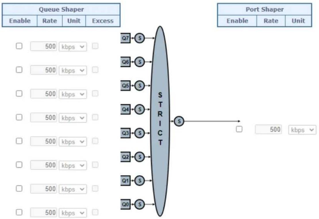
flowchart
graph LR
    subgraph_Queue_Shaper["Queue Shaper"]
        A1["Enable"] --> B1["Rate"] --> C1["Unit"] --> D1["Excess"]
        E1[" "] --> F1["500 kbps"]
        G1[" "] --> H1["500 kbps"]
        I1[" "] --> J1["500 kbps"]
        K1[" "] --> L1["500 kbps"]
        M1[" "] --> N1["500 kbps"]
        O1[" "] --> P1["500 kbps"]
        Q1[" "] --> R1["500 kbps"]
        S1[" "] --> T1["500 kbps"]
    end

    subgraph_Port_Shaper["Port Shaper"]
        U1["Enable"] --> V1["Rate"] --> W1["Unit"]
        X1[" "] --> Y1["500 kbps"]
        Z1[" "] --> AA1["500 kbps"]
        AB1[" "] --> AC1["500 kbps"]
        AD1[" "] --> AE1["500 kbps"]
        AF1[" "] --> AG1["500 kbps"]
        AH1[" "] --> AI1["500 kbps"]
        AJ1[" "] --> AK1["500 kbps"]
        AL1[" "] --> AM1["500 kbps"]
        AN1[" "] --> AO1["500 kbps"]
        AP1[" "] --> AQ1["500 kbps"]
        AR1[" "] --> AS1["500 kbps"]
        AT1[" "] --> AU1["500 kbps"]
        AV1[" "] --> AW1["500 kbps"]
    end

    F2["STRICT"] --> S2["S"]
    G2["S"] --> S2
    H2["S"] --> S2
    I2["S"] --> S2
    Q2["S"] --> S2
    Q3["S"] --> S2
    Q4["S"] --> S2
    Q5["S"] --> S2
    Q6["S"] --> S2
    Q7["S"] --> S2
    style STRICT fill:#999,stroke:#333,stroke-width:2px
Figure 4-4-2-2: QoS Egress Port Schedule and Shapers Page Screenshot
The page includes the following fields:
| Object Description | |
| Schedule Mode | Controls whether the scheduler mode is "Strict Priority" or "Weighted" on this switch port. |
| Queue Shaper Enable | Controls whether the queue shaper is enabled for this queue on this switch port. |
| Queue Shaper Rate | Controls the rate for the queue shaper.This value is restricted to 100-1000000 when the "Unit" is "kbps", and it is restricted to 1-13200 when the "Unit" is "Mbps".The default value is 500. |
| Queue Shaper Unit | Controls the unit of measure for the queue shaper rate as "kbps" or "Mbps".The default value is "kbps". |
| Queue Shaper Excess | Controls whether the queue is allowed to use excess bandwidth. |
| Queue Scheduler Weight | Controls the weight for this queue.This value is restricted to 1-100. This parameter is only shown if "Scheduler Mode" is set to "Weighted".The default value is "17". |
| Queue Scheduler Percent | Shows the weight in percent for this queue. This parameter is only shown if "Scheduler Mode" is set to "Weighted". |
| Port Shaper Enable | Controls whether the port shaper is enabled for this switch port. |
| Port Shaper Rate | Controls the rate for the port shaper.This value is restricted to 100-1000000 when the "Unit" is "kbps", and it is restricted to 1-13200 when the "Unit" is "Mbps".The default value is 500. |
| Port Shaper Unit | Controls the unit of measure for the port shaper rate as "kbps" or "Mbps".The default value is "kbps". |
Buttons
Apply
: Click to apply changes
Reset
: Click to undo any changes made locally and revert to previously saved values.
Cancel
: Click to undo any changes made locally and return to the previous page.
4.4.2.3 Port Shaping
This page provides an overview of QoS Egress Port Shapers for all switch ports. The Port shaping screen in Figure 4-4-2-3 appears.
QoS Egress Port Shapers
| Port | Shapers | ||||||||
| Q0 | Q1 | Q2 | Q3 | Q4 | Q5 | Q6 | Q7 | Port | |
| 12 | - | - | - | - | - | - | - | - | - |
| 34 | - | - | - | - | - | - | - | - | - |
| 56 | - | - | - | - | - | - | - | - | - |
| 78 | - | - | - | - | - | - | - | - | - |
| 910 | - | - | - | - | - | - | - | - | - |
QoS Egress Port Scheduler and Shapers Port 1
| Scheduler Mode | Strict Priority |
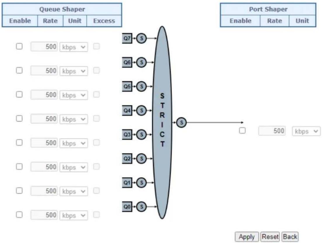
flowchart
graph TD
    subgraph_Queue_Shaper["Queue Shaper"]
        A1["Enable"] --> B1["Rate"] --> C1["Unit"] --> D1["Excess"]
        E1["□"] --> F1["500 kbps ▼"]
        G1["□"] --> H1["500 kbps ▼"]
        I1["□"] --> J1["500 kbps ▼"]
        K1["□"] --> L1["500 kbps ▼"]
        M1["□"] --> N1["500 kbps ▼"]
        O1["□"] --> P1["500 kbps ▼"]
        Q1["□"] --> R1["500 kbps ▼"]
        S1["□"] --> T1["500 kbps ▼"]
        U1["□"] --> V1["500 kbps ▼"]
        W1["□"] --> X1["500 kbps ▼"]
        Y1["□"] --> Z1["500 kbps ▼"]
    end

    subgraph_Port_Shaper["Port Shaper"]
        AA["Enable"] --> AB["Rate"] --> AC["Unit"]
        AD["□"] --> AE["500 kbps ▼"]
        AF["□"] --> AG["500 kbps ▼"]
        AH["□"] --> AI["500 kbps ▼"]
        AJ["□"] --> AK["500 kbps ▼"]
        AL["□"] --> AM["500 kbps ▼"]
        AN["□"] --> AO["500 kbps ▼"]
        AP["□"] --> AQ["500 kbps ▼"]
        AR["□"] --> AS["500 kbps ▼"]
    end

    A2["Q7"] --> B2["S"]
    A3["Q6"] --> B3["S"]
    A4["Q5"] --> B4["S"]
    A5["Q4"] --> B5["S"]
    A6["Q3"] --> B6["S"]
    A7["Q2"] --> B7["S"]
    A8["Q1"] --> B8["S"]
    A9["Q0"] --> B9["S"]
    B1 & B2 & B3 & B4 & B5 & B6 & B7 & B8 & B9 --> STRICT
    STRICT --> S
    S --> PortShaper
    S --> PortShaper
    style PortShaper fill:#f9f,stroke:#333,stroke-width:2px
    note right of Port Shaper
        Apply Reset Back
    end
Figure 4-4-2-3: QoS Egress Port Schedule and Shapers Page Screenshot
The page includes the following fields:
| Object Description | |
| Schedule Mode | Controls whether the scheduler mode is "Strict Priority" or "Weighted" on this switch port. |
| Queue Shaper Enable | Controls whether the queue shaper is enabled for this queue on this switch port. |
| Queue Shaper Rate | Controls the rate for the queue shaper.This value is restricted to 100-1000000 when the "Unit" is "kbps", and it is restricted to 1-13200 when the "Unit" is "Mbps".The default value is 500. |
| Queue Shaper Unit | Controls the unit of measure for the queue shaper rate as "kbps" or "Mbps".The default value is "kbps". |
| Queue Shaper Excess | Controls whether the queue is allowed to use excess bandwidth. |
| Queue Scheduler Weight | Controls the weight for this queue.This value is restricted to 1-100. This parameter is only shown if "Scheduler Mode" is set to "Weighted".The default value is "17". |
| Queue Scheduler Percent | Shows the weight in percent for this queue. This parameter is only shown if "Scheduler Mode" is set to "Weighted". |
| Port Shaper Enable | Controls whether the port shaper is enabled for this switch port. |
| Port Shaper Rate | Controls the rate for the port shaper.This value is restricted to 100-1000000 when the "Unit" is "kbps", and it is restricted to 1-13200 when the "Unit" is "Mbps".The default value is 500. |
| Port Shaper Unit | Controls the unit of measure for the port shaper rate as "kbps" or "Mbps".The default value is "kbps". |
Buttons
Apply
: Click to apply changes
Reset
: Click to undo any changes made locally and revert to previously saved values.
Cancel
: Click to undo any changes made locally and return to the previous page.
4.4.3 Storm Control
4.4.3.1 Storm Policing Configuration
Storm control for the switch is configured on this page. There is a unicast storm rate control, multicast storm rate control, and a broadcast storm rate control. These only affect flooded frames, i.e. frames with a (VLAN ID, DMAC) pair not present on the MAC Address table.
The configuration indicates the permitted packet rate for unicast, multicast or broadcast traffic across the switch.
The Storm Control Configuration screen in Figure 4-4-3-1 appears.
Global Storm Policer Configuration
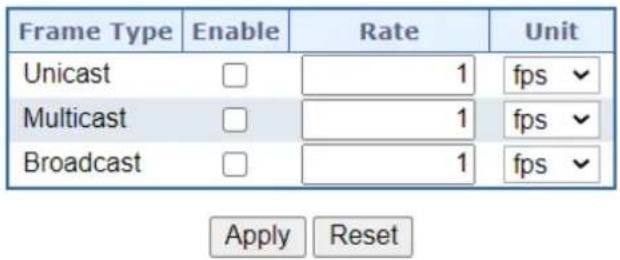
Figure 4-4-3-1: Storm Control Configuration Page Screenshot
The page includes the following fields:
| Object Description | |
| • Port | The port number for which the configuration below applies. |
| • Enable | Controls whether the storm control is enabled on this switch port. |
| • Rate | Controls the rate for the global storm policer. This value is restricted to 1-1024000 when "Unit" is fps, and 1-1024 when "Unit" is kfps. The rate is internally rounded up to the nearest value supported by the global storm policer. Supported rates are 1, 2, 4, 8, 16, 32, 64, 128, 256 and 512 fps for rates <= 512 fps and 1, 2, 4, 8, 16, 32, 64, 128, 256, 512 and 1024 kfps for rates >512 fps. |
| • Unit | Controls the unit of measure for the global storm policer rate as fps or kfps.. |
Buttons
Apply
: Click to apply changes
Reset
: Click to undo any changes made locally and revert to previously saved values.
4.4.4 Differentiated Service
4.4.4.1 Port DSCP
This page allows you to configure the basic QoS Port DSCP Configuration settings for all switch ports. The Port DSCP screen in Figure 4-9-8 appears.
QoS Port DSCP Configuration
| Port | Ingress | Egress | ||
| Translate | Classify | Rewrite | ||
| * | □ | √ | ||
| 1 | □ | Disable √ | Disable | √ |
| 2 | □ | Disable √ | Disable | √ |
| 3 | □ | Disable √ | Disable | √ |
| 4 | □ | Disable √ | Disable | √ |
| 5 | □ | Disable √ | Disable | √ |
| 6 | □ | Disable √ | Disable | √ |
| 7 | □ | Disable √ | Disable | √ |
| 8 | □ | Disable √ | Disable | √ |
| 9 | □ | Disable √ | Disable | √ |
| 10 | □ | Disable √ | Disable | √ |

Figure 4-4-4-1: QoS Port DSCP Configuration Page Screenshot
The page includes the following fields:
| Object Description | |
| • Port | The Port column shows the list of ports for which you can configure dscp ingress and egress settings. |
| • Ingress | In Ingress settings you can change ingress translation and classification settings for individual ports.There are two configuration parameters available in Ingress:■Translate■Classify |
| • Translate | To Enable the Ingress Translation click the checkbox. |
| • Classify | Classification for a port have 4 different values.■Disable: No Ingress DSCP Classification.■DSCP=0: Classify if incoming (or translated if enabled) DSCP is 0.■Selected: Classify only selected DSCP for which classification is enabled as specified in DSCP Translation window for the specific DSCP.■All: Classify all DSCP. |
| • Egress | Port Egress Rewriting can be one of -■ Disable: No Egress rewrite.■ Enable: Rewrite enable without remapped.■ Remap DP Unaware: DSCP from analyzer is remapped and frame is remarked with remapped DSCP value. The remapped DSCP value is always taken from the 'DSCP Translation->Egress Remap DP0' table.■ Remap DP Aware: DSCP from analyzer is remapped and frame is remarked with remapped DSCP value. Depending on the DP level of the frame, the remapped DSCP value is either taken from the 'DSCP Translation->Egress Remap DP0' table or from the 'DSCP Translation->Egress Remap DP1' table. |
Buttons
Save
: Click to apply changes
Reset
: Click to undo any changes made locally and revert to previously saved values.
4.4.4.2 DSCP-based QoS
This page allows you to configure the basic QoS DSCP-based QoS Ingress Classification settings for all switches. The DSCP-based QoS screen in Figure 4-4-4-2 appears.
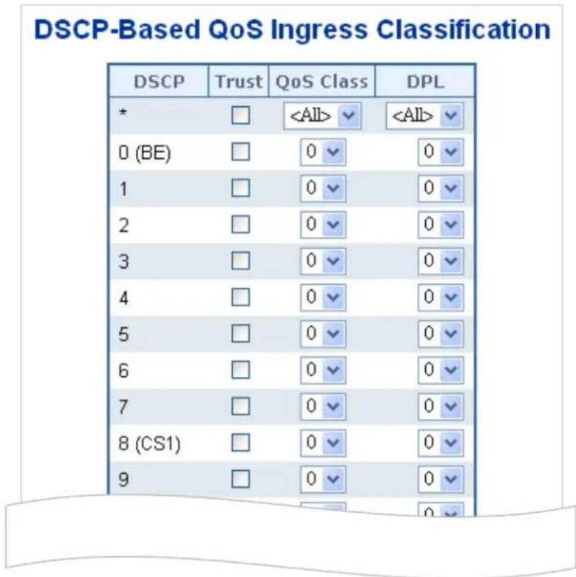
other
DSCP-Based QoS Ingress Classification | DSCP | Trust | QoS Class | DPL | | :--- | :--- | :--- | :--- | | * | □ |Figure 4-4-4-2: DSCP-based QoS Ingress Classification Page Screenshot
The page includes the following fields:
| Object Description | |
| • DSCP | Maximum number of supported DSCP values are 64. |
| • Trust | Controls whether a specific DSCP value is trusted. Only frames with trusted DSCP values are mapped to a specific QoS class and Drop Precedence Level. Frames with untrusted DSCP values are treated as a non-IP frame. |
| • QoS Class | QoS Class value can be any of (0-7) |
| • DPL | Drop Precedence Level (0-1) |
4.4.4.3 DSCP Translation
This page allows you to configure the basic QoS DSCP Translation settings for all switches. DSCP translation can be done in Ingress or Egress. The DSCP Translation screen in Figure 4-4-4-3 appears.
DSCP Translation
| DSCP | Ingress | Egress | ||
| Translate | Classify | Remap DPO | Remap DP1 | |
| * | ||||
| 0 (BE) | 0 (BE) | 0 (BE) | 0 (BE) | |
| 1 | 1 | 1 | 1 | |
| 2 | 2 | 2 | 2 | |
| 3 | 3 | 3 | 3 | |
| 4 | 4 | 4 | 4 | |
| 5 | 5 | 5 | 5 | |
| 6 | 6 | 6 | 6 | |
| 7 | 7 | 7 | 7 | |
| 8 (CS1) | 8 (CS1) | 8 (CS1) | 8 (CS1) | |
| 9 | 9 | 9 | 9 | |
Figure 4-4-4-3: DSCP Translation Page Screenshot
The page includes the following fields:
| Object Description | |
| • DSCP | Maximum number of supported DSCP values are 64 and valid DSCP value ranges from 0 to 63. |
| • Ingress | Ingress side DSCP can be first translated to new DSCP before using the DSCP for QoS class and DPL map.There are two configuration parameters for DSCP Translation –■ Translate■ Classify |
| • Translate | DSCP at Ingress side can be translated to any of (0-63) DSCP values. |
| • Classify | Click to enable Classification at Ingress side. |
| • Egress | There is following configurable parameter for Egress side -■ Remap |
| • Remap DP | Select the DSCP value from select menu to which you want to remap. DSCP value ranges form 0 to 63. |
Buttons
Apply
: Click to apply changes
Reset
Click to undo any changes made locally and revert to previously saved values.
4.4.4.4 DSCP Classification
This page allows you to map DSCP value to a QoS Class and DPL value. The DSCP Classification screen in Figure 4-4-4-4 appears.
DSCP Classification
| CoS | DSCP DP0 | DSCP DP1 | ||
| * | ✓ | ✓ | ||
| 0 | 0 (BE) | ✓ | 0 (BE) | ✓ |
| 1 | 0 (BE) | ✓ | 0 (BE) | ✓ |
| 2 | 0 (BE) | ✓ | 0 (BE) | ✓ |
| 3 | 0 (BE) | ✓ | 0 (BE) | ✓ |
| 4 | 0 (BE) | ✓ | 0 (BE) | ✓ |
| 5 | 0 (BE) | ✓ | 0 (BE) | ✓ |
| 6 | 0 (BE) | ✓ | 0 (BE) | ✓ |
| 7 | 0 (BE) | ✓ | 0 (BE) | ✓ |
Apply Reset
Figure 4-4-4-4: DSCP Classification Page Screenshot
The page includes the following fields:
| Object Description | |
| • QoS Class | Available QoS Class value ranges from 0 to 7. QoS Class (0-7) can be mapped to followed parameters. |
| • DPL | Actual Drop Precedence Level. |
| • DSCP | Select DSCP value (0-63) from DSCP menu to map DSCP to corresponding QoS Class and DPL value |
Buttons

: Click to apply changes

: Click to undo any changes made locally and revert to previously saved values.
4.4.5 QCL
4.4.5.1 QoS Control List
This page shows the QoS Control List(QCL), which is made up of the QCEs. Each row describes a QCE that is defined. The maximum number of QCEs is 256 on each switch.
Click on the lowest plus sign to add a new QCE to the list. The QoS Control List screen in Figure 4-4-5-1 appears.
QoS Control List Configuration
| QCE | Port | DMAC | SMAC | Tag Type | VID | PCP | DEI | Frame Type | Action | ||||||
| CoS | DPL | DSCP | PCP | DEI | Policy | ||||||||||
Figure 4-4-5-1: QoS Control List Configuration Page Screenshot
The page includes the following fields:
| Object Description | |
| • QCE# | Indicates the index of QCE. |
| • Port | Indicates the list of ports configured with the QCE. |
| • DMAC | Specify the type of Destination MAC addresses for incoming frame. Possible values are:■ Any: All types of Destination MAC addresses are allowed.■ Unicast: Only Unicast MAC addresses are allowed.■ Multicast: Only Multicast MAC addresses are allowed.■ Broadcast: Only Broadcast MAC addresses are allowed.The default value is 'Any'. |
| • SMAC | Displays the OUI field of Source MAC address, i.e. first three octet (byte) of MAC address. |
| • Tag Type | Indicates tag type. Possible values are:■ Any: Match tagged and untagged frames.■ Untagged: Match untagged frames.■ Tagged: Match tagged frames.The default value is 'Any' |
| • VID | Indicates (VLAN ID), either a specific VID or range of VIDs. VID can be in the range 1-4095 or 'Any' |
| • PCP | Priority Code Point: Valid value PCP are specific(0, 1, 2, 3, 4, 5, 6, 7) or range(0-1, 2-3, 4-5, 6-7, 0-3, 4-7) or 'Any'. |
| • DEI | Drop Eligible Indicator: Valid value of DEI can be any of values between 0, 1 or 'Any'. |
| • Frame Type | Indicates the type of frame to look for incoming frames. Possible frame types are:■ Any: The QCE will match all frame type.■ Ethernet: Only Ethernet frames (with Ether Type 0x600-0xFFFF) are allowed.■ LLC: Only (LLC) frames are allowed.■ SNAP: Only (SNAP) frames are allowed.■ IPv4: The QCE will match only IPV4 frames.■ IPv6: The QCE will match only IPV6 frames. |
| • Action | Indicates the classification action taken on ingress frame if parameters configured are matched with the frame's content.Possible actions are:CoS: Classify Class of Service.DPL: Classify Drop Precedence Level.DSCP: Classify DSCP value.PCP: Classify PCP value.DEI: Classify DEI value.Policy: Classify ACL Policy number. |
| • Modification Buttons | You can modify each QCE in the table using the following buttons:+: Inserts a new QCE before the current row.⊕: Edits the QCE.↑: Moves the QCE up the list.↓: Moves the QCE down the list.✕: Deletes the QCE.+: The lowest plus sign adds a new entry at the bottom of the list of QCL. |
4.4.5.2 QoS Control Entry Configuration
The QCE Configuration screen in Figure 4-4-5-2 appears.
QCE Configuration
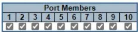
Key Parameters
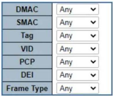
Action Parameters
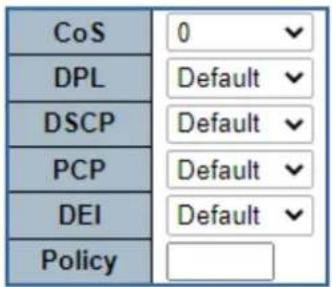

Figure 4-4-5-2: QCE Configuration Page Screenshot
The page includes the following fields:
| Object Description | |
| • Port Members | Check the checkbox button in case you what to make any port member of the QCL entry. By default all ports will be checked |
| • Key Parameters | Key configuration are described as below:■DMAC Type Destination MAC type: possible values are unicast(UC), multicast(MC), broadcast(BC) or 'Any'■SMAC Source MAC address: 24 MS bits (OUI) or 'Any'■Tag Value of Tag field can be 'Any', 'Untag' or 'Tag'■VID Valid value of VLAN ID can be any value in the range 1-4095 or 'Any'; user can enter either a specific value or a range of VIDs■PCP Priority Code Point: Valid value PCP are specific(0, 1, 2, 3, 4, 5, 6, 7) or range(0-1, 2-3, 4-5, 6-7, 0-3, 4-7) or 'Any'■DEI Drop Eligible Indicator: Valid value of DEI can be any of values between 0, 1 or 'Any'■Frame Type Frame Type can have any of the following values1. Any2. Ethernet3. LLC4. SNAP5. IPv46. IPv6Note: all frame types are explained below. |
| Any | Allow all types of frames. |
| EtherType | Ethernet Type Valid Ethernet type can have value within 0x600-0xFFFF or 'Any' but excluding 0x800(IPv4) and 0x86DD(IPv6), default value is 'Any'. |
| LLC | ■ SSAP Address Valid SSAP(Source Service Access Point) can vary from 0x00 to 0xFF or 'Any', the default value is 'Any'■ DSAP Address Valid DSAP(Destination Service Access Point) can vary from 0x00 to 0xFF or 'Any', the default value is 'Any'■ Control Address Valid Control Address can vary from 0x00 to 0xFF or 'Any', the default value is 'Any' |
| SNAP | PID Valid PID(a.k.a Ethernet type) can have value within 0x00-0xFFFF or 'Any', default value is 'Any' |
| IPv4 | ■ Protocol IP protocol number: (0-255, TCP or UDP) or 'Any'■ Source IP Specific Source IP address in value/mask format or 'Any'. IP and Mask are in the format x.y.z.w where x, y, z, and w are decimal numbers between 0 and 255. When Mask is converted to a 32-bit binary string and read from left to right, all bits following the first zero must also be zeroDSCP Diffserv Code Point value(DSCP): It can be specific value, range of value or 'Any'. DSCP values are in the range 0-63 including BE, CS1-CS7, EF or AF11-AF43■ IP Fragment IPv4 frame fragmented option: yes|no|any■ Sport Source TCP/UDP port:(0-65535) or 'Any', specific or port range applicable for IP protocol UDP/TCP■ Dport Destination TCP/UDP port:(0-65535) or 'Any', specific or port range applicable for IP protocol UDP/TCP |
| IPv6 | Protocol IP protocol number: (0-255, TCP or UDP) or 'Any'Source IP IPv6 source address: (a.b.c.d) or 'Any', 32 LS bitsDSCP Diffserv Code Point value(DSCP): It can be specific value, range of value or 'Any'. DSCP values are in the range 0-63 including BE, CS1-CS7, EF or AF11-AF43Sport Source TCP/UDP port:(0-65535) or 'Any', specific or port range applicable for IP protocol UDP/TCPDport Destination TCP/UDP port:(0-65535) or 'Any', specific or port range applicable for IP protocol UDP/TCP |
| Action Parameters | CoS Class of Service: (0-7) or 'Default'.DPL Drop Precedence Level: (0-1) or 'Default'.DSCP DSCP: (0-63, BE, CS1-CS7, EF or AF11-AF43) or 'Default'.PCP PCP: (0-7) or 'Default'. Note: PCP and DEI cannot be set individually.DEI DEI: (0-1) or 'Default'.Policy ACL Policy number: (0-255) or 'Default' (empty field).'Default' means that the default classified value is not modified by this QCE. |
Buttons
Apply
: Click to apply changes
Reset
: Click to undo any changes made locally and revert to previously saved values
Cancel
Return to the previous page without saving the configuration change
4.4.5.3 QCL Status
This page shows the QCL status by different QCL users. Each row describes the QCE that is defined. It is a conflict if a specific QCE is not applied to the hardware due to hardware limitations. The maximum number of QCEs is 256 on each switch. The QoS Control List Status screen in Figure 4-4-5-3 appears.

QoS Control List Status
| User | QCE | Port | Frame Type | Action | Conflict | |||||
| CoS | DPL | DSCP | PCP | DEI | Policy | |||||
| No entries | ||||||||||
Figure 4-4-5-3: QoS Control List Status Page Screenshot
The page includes the following fields:
| Object Description | |
| User | Indicates the QCL user. |
| QCE# | Indicates the index of QCE. |
| Port | Indicates the list of ports configured with the QCE. |
| Frame Type | Indicates the type of frame to look for incoming frames. Possible frame types are:■ Any: The QCE will match all frame types.■ Ethernet: Only Ethernet frames (with Ether Type 0x600-0xFFFF) are allowed.■ LLC: Only (LLC) frames are allowed.SNAP: Only (SNAP) frames are allowed.IPv4: The QCE will match only IPV4 frames.IPv6: The QCE will match only IPV6 frames. |
| • Action | Indicates the classification action taken on ingress frame if parameters configured are matched with the frame's content.Possible actions are:CoS: Classify Class of Service.DPL: Classify Drop Precedence Level.DSCP: Classify DSCP value.PCP: Classify PCP value.DEI: Classify DEI value.Policy: Classify ACL Policy number. |
| • Conflict | Displays Conflict status of QCL entries. As H/W resources are shared by multiple applications. It may happen that resources required to add a QCE may not be available, in that case it shows conflict status as 'Yes', otherwise it is always 'No'.Please note that conflict can be resolved by releasing the H/W resources required to add QCL entry on pressing 'Resolve Conflict' button. |
Buttons
Combined
Select the QCL status from this drop down list.
Auto-refresh ☐: Check this box to refresh the page automatically. Automatic refresh occurs every 3 seconds.
Resolve Conflict
Click to release the resources required to add QCL entry, in case the conflict status for any QCL entry is
'yes'.
Refresh
Click to refresh the page.
4.4.5.4 Voice VLAN Configuration
The Voice VLAN feature enables voice traffic forwarding on the Voice VLAN, then the switch can classify and schedule network traffic. It is recommended that there be two VLANs on a port - one for voice, one for data.
Before connecting the IP device to the switch, the IP phone should configure the voice VLAN ID correctly. It should be configured through its own GUI. The Voice VLAN Configuration screen in Figure 4-4-5-4 appears.
Voice VLAN Configuration
| Mode | Disabled | |
| VLAN ID | 1000 | |
| Aging Time | 86400 | seconds |
| Traffic Class | 7 (High) | |
Port Configuration
| Port | Mode | Security | Discovery Protocol |
| * | |||
| 1 | Disabled | Disabled | OUI |
| 2 | Disabled | Disabled | OUI |
| 3 | Disabled | Disabled | OUI |
| 4 | Disabled | Disabled | OUI |
| 5 | Disabled | Disabled | OUI |
| 6 | Disabled | Disabled | OUI |
| 7 | Disabled | Disabled | OUI |
| 8 | Disabled | Disabled | OUI |
| 9 | Disabled | Disabled | OUI |
| 10 | Disabled | Disabled | OUI |
Figure 4-4-5-4: Voice VLAN Configuration Page Screenshot
The page includes the following fields:
| Object Description | |
| • Mode | Indicates the Voice VLAN mode operation. We must disable MSTP feature before we enable Voice VLAN. It can avoid the conflict of ingress filter. Possible modes are:■ Enabled: Enable Voice VLAN mode operation.■ Disabled: Disable Voice VLAN mode operation. |
| • VLAN ID | Indicates the Voice VLAN ID. It should be a unique VLAN ID in the system and cannot equal each port PVID. It is conflict configuration if the value equal management VID, MVR VID, PVID etc.The allowed range is 1 to 4095. |
| • Aging Time | Indicates the Voice VLAN secure learning age time. The allowed range is 10 to 10000000 seconds. It used when security mode or auto detect mode is enabled.In other cases, it will based hardware age time.The actual age time will be situated in the [age_time; 2 * age_time] interval. |
| • Traffic Class | Indicates the Voice VLAN traffic class. All traffic on Voice VLAN will apply this class. |
| • Mode | Indicates the Voice VLAN port mode.Possible port modes are:■Disabled: Disjoin from Voice VLAN.■Auto: Enable auto detect mode. It detects whether there is VoIP phone attached to the specific port and configures the Voice VLAN members automatically.■Forced: Force join to Voice VLAN. |
| • Port Security | Indicates the Voice VLAN port security mode. When the function is enabled, all non-telephone MAC address in Voice VLAN will be blocked 10 seconds. Possible port modes are:■Enabled: Enable Voice VLAN security mode operation.■Disabled: Disable Voice VLAN security mode operation. |
| • Port Discovery Protocol | Indicates the Voice VLAN port discovery protocol. It will only work when auto detect mode is enabled. We should enable LLDP feature before configuring discovery protocol to "LLDP" or "Both". Changing the discovery protocol to "OUI" or "LLDP" will restart auto detect process. Possible discovery protocols are:■OUI: Detect telephony device by OUI address.■LLDP: Detect telephony device by LLDP.■Both: Both OUI and LLDP. |
4.4.5.5 Voice VLAN OUI Table
Configure VOICE VLAN OUI table on this page. The maximum entry number is 16. Modifying the OUI table will restart auto detection of OUI process. The Voice VLAN OUI Table screen in Figure 4-4-5-5 appears.
Voice VLAN OUI Table
| Delete | Telephony OUI | Description |
| 00-01-e3 | Siemens AG phones | |
| 00-03-6b | Cisco phones | |
| 00-0f-e2 | H3C phones | |
| 00-30-4f | Planet phones | |
| 00-60-b9 | Philips and NEC AG phones | |
| 00-d0-1e | Pingtel phones | |
| 00-e0-75 | Polycom phones | |
| 00-e0-bb | 3Com phones |
Add New Entry
Apply Reset
Figure 4-4-5-5: Voice VLAN OUI Table Page Screenshot
The page includes the following fields:
| Object Description | |
| Delete | Check to delete the entry. It will be deleted during the next save. |
| Telephony OUI | An telephony OUI address is a globally unique identifier assigned to a vendor by IEEE. It must be 6 characters long and the input format is "xx-xx-xx" (x is a hexadecimal digit). |
| Description | The description of OUI address. Normally, it describes which vendor telephony device it belongs to.The allowed string length is 0 to 32. |
Buttons
Add New Entry
Click to add a new access management entry.
Apply
: Click to apply changes
Reset
: Click to undo any changes made locally and revert to previously saved values.
4.5 Security
4.5.1 Access Security
4.5.1.1 Access Management
Configure access management table on this page. The maximum entry number is 16. If the application's type match any one of the access management entries, it will allow access to the switch. The Access Management Configuration screen in Figure 4-5-1-1 appears.
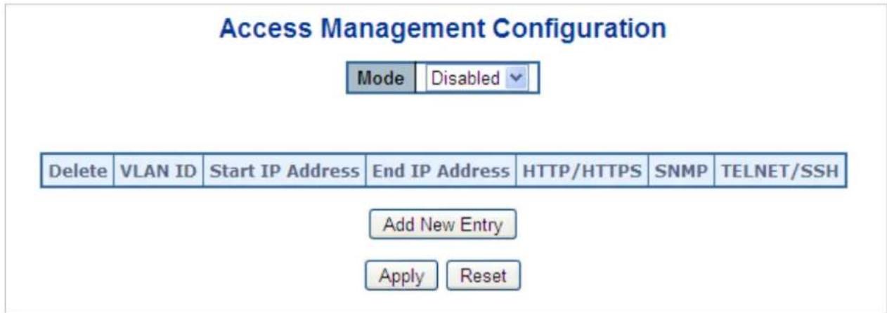
Figure 4-5-1-1: Access Management Configuration Overview Page Screenshot
The page includes the following fields:
| Object Description | |
| • Mode | Indicates the access management mode operation. Possible modes are:Enabled: Enable access management mode operation level. Disabled: Disable access management mode operation. |
| • Delete | Check to delete the entry. It will be deleted during the next apply . |
| • VLAN ID | Indicates the VLAN ID for the access management entry. |
| • Start IP address | Indicates the start IP address for the access management entry. |
| • End IP address | Indicates the end IP address for the access management entry. |
| • HTTP/HTTPS | Indicates the host can access the switch from HTTP/HTTPS interface that the host IP address matched the entry. |
| • SNMP | Indicates the host can access the switch from SNMP interface that the host IP address matched the entry. |
| • Telnet/SSH | Indicates the host can access the switch from TELNET/SSH interface that the host IP address matched the entry. |
Buttons
Add New Entry
Click to add a new access management entry.
Apply
: Click to apply changes
Reset
: Click to undo any changes made locally and revert to previously saved values.
4.5.1.2 Access Management Statistics
This page provides statistics for access management. The Access Management Statistics screen in Figure 4-5-1-2 appears.
Access Management Statistics
| Interface | Received Packets | Allowed Packets | Discarded Packets |
| HTTP | 0 | 0 | 0 |
| HTTPS | 0 | 0 | 0 |
| SNMP | 0 | 0 | 0 |
| TELNET | 0 | 0 | 0 |
| SSH | 0 | 0 | 0 |
Figure 4-5-1-2: Access Management Statistics Overview Page Screenshot
The page includes the following fields:
| Object Description | |
| • Interface | The interface that allowed remote host can access the switch. |
| • Receive Packets | The received packets number from the interface under access management mode is enabled. |
| • Allow Packets | The allowed packets number from the interface under access management mode is enabled. |
| • Discard Packets | The discarded packets number from the interface under access management mode is enabled. |
Buttons
Auto-refresh ☐: Check this box to refresh the page automatically. Automatic refresh occurs every 3 seconds.
Refresh
Click to refresh the page immediately.
Clear
: Clears all statistics.
4.5.1.3 SSH
Configure SSH on this page. This page shows the Port Security status. Port Security is a module with no direct configuration. Configuration comes indirectly from other modules - the user modules. When a user module has enabled port security on a port, the port is set-up for software-based learning. In this mode, frames from unknown MAC addresses are passed on to the port security module, which in turn asks all user modules whether to allow this new MAC address to forward or block it. For a MAC address to be set in the forwarding state, all enabled user modules must unanimously agree on allowing the MAC address to forward. If only one chooses to block it, it will be blocked until that user module decides otherwise.
The status page is divided into two sections - one with a legend of user modules and one with the actual port status. The SSH Configuration screen in Figure 4-5-1-3 appears.
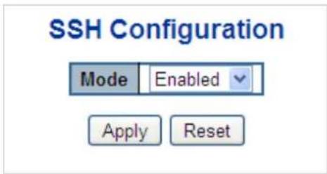
Figure 4-5-1-3: SSH Configuration Screen Page Screenshot
The page includes the following fields:
| Object Description | |
| • Mode | Indicates the SSH mode operation. Possible modes are:■ Enabled: Enable SSH mode operation.■ Disabled: Disable SSH mode operation. |
Buttons
Apply
: Click to apply changes
Reset
: Click to undo any changes made locally and revert to previously saved values.
4.5.1.4 HTTPS
Configure HTTPS on this page. The HTTPS Configuration screen in Figure 4-5-1-4 appears.
HTTPS Configuration
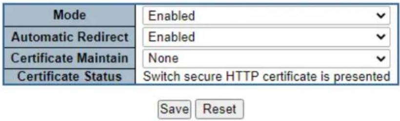
Figure 4-5-1-4: HTTPS Configuration Screen Page Screenshot
The page includes the following fields:
| Object Description | |
| • Mode | Indicates the HTTPS mode operation. When the current connection is HTTPS, to apply HTTPS disabled mode operation will automatically redirect web browser to an HTTP connection. Possible modes are:■ Enabled: Enable HTTPS mode operation.■ Disabled: Disable HTTPS mode operation. |
| • Automatic Redirect | Indicates the HTTPS redirect mode operation. It only significant if HTTPS mode "Enabled" is selected. Automatically redirects web browser to an HTTPS connection when both HTTPS mode and Automatic Redirect are enabled or redirects web browser to an HTTP connection when both are disabled. Possible modes are:■ Enabled: Enable HTTPS redirect mode operation.■ Disabled: Disable HTTPS redirect mode operation. |
| • Certificate Maintain | The operation of certificate maintenance.Possible operations are:None: No operation.Delete: Delete the current certificate.Upload: Upload a certificate PEM file. Possible methods are: Web Browser or URL.Generate: Generate a new self-signed RSA certificate. |
| • Certificate Pass Phrase | Enter the pass phrase in this field if your uploading certificate is protected by a specific passphrase. |
| • Certificate Upload | Upload a certificate PEM file into the switch. The file should contain the certificate and private key together. If you have two separated files for saving certificate and private key. Use the Linux cat command to combine them into a single PEM file. For example, cat my.cert my.key > my.pemNotice that the RSA certificate is recommended since most of the new version of browsers has removed support for DSA in certificate, e.g. Firefox v37 and Chrome v39.Possible methods are:Web Browser: Upload a certificate via Web browser.URL: Upload a certificate via URL, the supported protocols are HTTP, HTTPS, TFTP and FTP. The URL format is://[<username>@]<host>[:<port>]//. For example, tftp://10.10.10/ new_image_path/new_image.dat, http://username:password@10.10.10.10:80/new_image_path/new_image.dat. A valid file name is a text string drawn from alphabet (A-Za-z), digits (0-9), dot (.), hyphen (-), under score( ). The maximum length is 63 and hyphen must not be first character. The file name content that only contains '.' is not allowed. |
| • Certificate Status | Display the current status of certificate on the switch.Possible statuses are:Switch secure HTTP certificate is presented.Switch secure HTTP certificate is not presented.Switch secure HTTP certificate is generating ... |
Buttons
Save
Click to save changes.
Reset
Click to undo any changes made locally and revert to previously saved values.
4.5.2 AAA
This section is to control the access to the Managed Metro Switch, including the user access and management control. The Authentication section contains links to the following main topics:
■ User Authentication
■ IEEE 802.1X Port-based Network Access Control
■ MAC-based Authentication
Overview of 802.1X (Port-Based) Authentication
In the 802.1X-world, the user is called the supplicant, the switch is the authenticator, and the RADIUS server is the authentication server. The switch acts as the man-in-the-middle, forwarding requests and responses between the supplicant and the authentication server. Frames sent between the supplicant and the switch are special 802.1X frames, known as EAPOL (EAP Over LANs) frames. EAPOL frames encapsulate EAP PDUs (RFC3748). Frames sent between the switch and the RADIUS server are RADIUS packets. RADIUS packets also encapsulate EAP PDUs together with other attributes like the switch's IP address, name, and the supplicant's port number on the switch. EAP is very flexible, in that it allows for different authentication methods, like MD5-Challenge, PEAP, and TLS. The important thing is that the authenticator (the switch) doesn't need to know which authentication method the supplicant and the authentication server are using, or how many information exchange frames are needed for a particular method. The switch simply encapsulates the EAP part of the frame into the relevant type (EAPOL or RADIUS) and forwards it.
When authentication is complete, the RADIUS server sends a special packet containing a success or failure indication. Besides forwarding this decision to the supplicant, the switch uses it to open up or block traffic on the switch port connected to the supplicant.
Overview of MAC-based Authentication
Unlike 802.1X, MAC-based authentication is not a standard, but merely a best-practices method adopted by the industry. In MAC-based authentication, users are called clients, and the switch acts as the supplicant on behalf of clients. The initial frame (any kind of frame) sent by a client is snooped by the switch, which in turn uses the client's MAC address as both username and password in the subsequent EAP exchange with the RADIUS server. The 6-byte MAC address is converted to a string on the following form "xx-xx-xx-xx-xx-xx", that is, a dash (-) is used as separator between the lower-cased hexadecimal digits. The switch only supports the MD5-Challenge authentication method, so the RADIUS server must be configured accordingly.
When authentication is complete, the RADIUS server sends a success or failure indication, which in turn causes the switch to open up or block traffic for that particular client, using static entries into the MAC Table. Only then will frames from the client be forwarded on the switch. There are no EAPOL frames involved in this authentication, and therefore, MAC-based Authentication has nothing to do with the 802.1X standard.
The advantage of MAC-based authentication over 802.1X is that several clients can be connected to the same port (e.g. through a 3rd party switch or a hub) and still require individual authentication, and that the clients don't need special supplicant software to authenticate. The disadvantage is that MAC addresses can be spoofed by malicious users, equipment whose MAC address is a valid RADIUS user can be used by anyone, and only the MD5-Challenge method is supported.
The 802.1X and MAC-Based Authentication configuration consists of two sections, a system- and a port-wide.
Overview of User Authentication
It is allowed to configure the Managed Metro Switch to authenticate users logging into the system for management access using local or remote authentication methods, such as telnet and Web browser. This Managed Metro Switch provides secure network management access using the following options:
■ Remote Authentication Dial-in User Service (RADIUS)
■ Terminal Access Controller Access Control System Plus (TACACS+)
■ Local user name and Privilege Level control
RADIUS and TACACS+ are logon authentication protocols that use software running on a central server to control access to RADIUS-aware or TACACS-aware devices on the network. An authentication server contains a database of multiple user name / password pairs with associated privilege levels for each user that requires management access to the Managed Metro Switch.
Understanding IEEE 802.1X Port-based Authentication
The IEEE 802.1X standard defines a client-server-based access control and authentication protocol that restricts unauthorized clients from connecting to a LAN through publicly accessible ports. The authentication server authenticates each client connected to a switch port before making available any services offered by the switch or the LAN.
Until the client is authenticated, 802.1X access control allows only Extensible Authentication Protocol over LAN (EAPOL) traffic through the port to which the client is connected. After authentication is successful, normal traffic can pass through the port.
This section includes this conceptual information:
- Device Roles
• Authentication Initiation and Message Exchange - Ports in Authorized and Unauthorized States
■ Device Roles
With 802.1X port-based authentication, the devices in the network have specific roles as shown below.
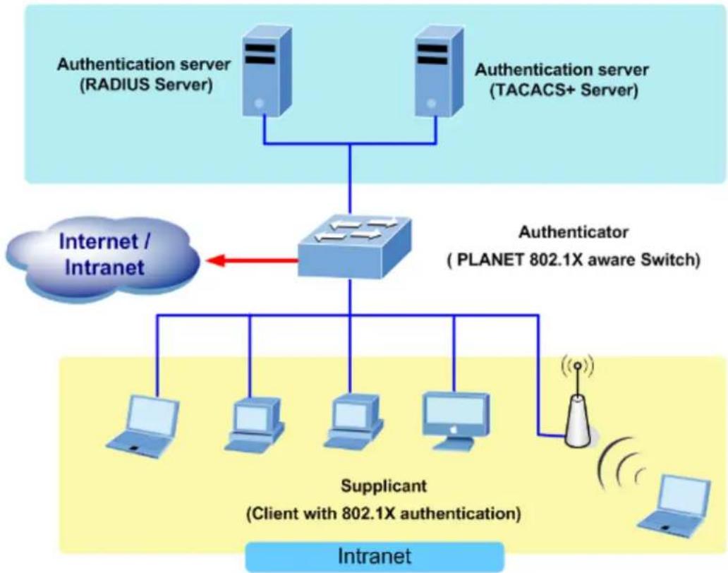
flowchart
graph TD
    A["Authentication server (RADIUS Server)"] --> C["Router"]
    B["Authentication server (TACACS+ Server)"] --> C
    C --> D["Authenticator (PLANET 802.1X aware Switch)"]
    D --> E["Supplicant (Client with 802.1X authentication)"]
    E --> F["Intranet"]
    E --> G["Intranet / Intranet"]
    style A fill:#cce5ff,stroke:#333
    style B fill:#cce5ff,stroke:#333
    style C fill:#cce5ff,stroke:#333
    style D fill:#cce5ff,stroke:#333
    style E fill:#cce5ff,stroke:#333
    style F fill:#cce5ff,stroke:#333
    style G fill:#cce5ff,stroke:#333
Figure 4-5-2-1
- Client—the device (workstation) that requests access to the LAN and switch services and responds to requests from the switch. The workstation must be running 802.1X-compliant client software such as that offered in the Microsoft Windows XP operating system. (The client is the supplicant in the IEEE 802.1X specification.)
- Authentication server—performs the actual authentication of the client. The authentication server validates the identity of the client and notifies the switch whether or not the client is authorized to access the LAN and switch services. Because the switch acts as the proxy, the authentication service is transparent to the client. In this release, the Remote Authentication Dial-In User Service (RADIUS) security system with Extensible Authentication Protocol (EAP) extensions is the only supported authentication server; it is available in Cisco Secure Access Control Server version 3.0. RADIUS operates in a client/server model in which secure authentication information is exchanged between the RADIUS server and one or more RADIUS clients.
- Switch (802.1X device)—controls the physical access to the network based on the authentication status of the client. The switch acts as an intermediary (proxy) between the client and the authentication server, requesting identity information from the client, verifying that information with the authentication server, and relaying a response to the client. The switch includes the RADIUS client, which is responsible for encapsulating and decapsulating the Extensible Authentication Protocol (EAP) frames and interacting with the authentication server. When the switch receives EAPOL frames and relays them to the authentication server, the Ethernet header is stripped and the remaining EAP frame is re-encapsulated in the RADIUS format. The EAP frames are not modified or examined during encapsulation, and the authentication server must support EAP within the native frame format. When the switch receives frames from the authentication server, the server's frame header is removed, leaving the EAP frame, which is then encapsulated for Ethernet and sent to the client.
■ Authentication Initiation and Message Exchange
The switch or the client can initiate authentication. If you enable authentication on a port by using the dot1x port-control auto interface configuration command, the switch must initiate authentication when it determines that the port link state transitions from down to up. It then sends an EAP-request/identity frame to the client to request its identity (typically, the switch sends an initial identity/request frame followed by one or more requests for authentication information). Upon receipt of the frame, the client responds with an EAP-response/identity frame.
However, if during bootup, the client does not receive an EAP-request/identity frame from the switch, the client can initiate authentication by sending an EAPOL-start frame, which prompts the switch to request the client's identity

If 802.1X is not enabled or supported on the network access device, any EAPOL frames from the client are dropped. If the client does not receive an EAP-request/identity frame after three attempts to start authentication, the client transmits frames as if the port is in the authorized state. A port in the authorized state effectively means that the client has been successfully authenticated.
When the client supplies its identity, the switch begins its role as the intermediary, passing EAP frames between the client and the authentication server until authentication succeeds or fails. If the authentication succeeds, the switch port becomes authorized.
The specific exchange of EAP frames depends on the authentication method being used. "Figure 4-5-2" shows a message exchange initiated by the client using the One-Time-Password (OTP) authentication method with a RADIUS server.
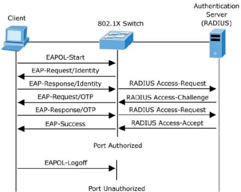
flowchart
graph TD
    A["Client"] -->|EAPOL-Start| B["802.1X Switch"]
    B -->|EAP-Request/Identity| A
    B -->|EAP-Response/Identity| A
    B -->|EAP-Request/OTP| B
    B -->|EAP-Response/OTP| B
    B -->|EAP-Success| A
    B -->|RADIUS Access-Request| C["Authentication Server (RADIUS)"]
    B -->|RADIUS Access-Challenge| C
    B -->|RADIUS Access-Request| C
    B -->|RADIUS Access-Accept| C
    D["EAPOL-Logoff"] --> E["Port Unauthorized"]
    F["Port Authorized"] --> G["Port Unauthorized"]
Figure 4-5-2-2: EAP Message Exchange
■ Ports in Authorized and Unauthorized States
The switch port state determines whether or not the client is granted access to the network. The port starts in the unauthorized state. While in this state, the port disallows all ingress and egress traffic except for 802.1X
protocol packets. When a client is successfully authenticated, the port transitions to the authorized state, allowing all traffic for the client to flow normally.
If a client that does not support 802.1X is connected to an unauthorized 802.1X port, the switch requests the client's identity. In this situation, the client does not respond to the request, the port remains in the unauthorized state, and the client is not granted access to the network.
In contrast, when an 802.1X-enabled client connects to a port that is not running the 802.1X protocol, the client initiates the authentication process by sending the EAPOL-start frame. When no response is received, the client sends the request for a fixed number of times. Because no response is received, the client begins sending frames as if the port is in the authorized state
If the client is successfully authenticated (receives an Accept frame from the authentication server), the port state changes to authorized, and all frames from the authenticated client are allowed through the port. If the authentication fails, the port remains in the unauthorized state, but authentication can be retried. If the authentication server cannot be reached, the switch can retransmit the request. If no response is received from the server after the specified number of attempts, authentication fails, and network access is not granted.
When a client logs off, it sends an EAPOL-logoff message, causing the switch port to transition to the unauthorized state.
If the link state of a port transitions from up to down, or if an EAPOL-logoff frame is received, the port returns to the unauthorized state.
4.5.2.1 Authentication Configuration
This page allows you to configure how a user is authenticated when he logs into the switch via one of the management client interfaces. The Authentication Method Configuration screen in Figure 4-5-2-3 appears.
Authentication Method Configuration
| Client | Methods | ||
| console | local ▼ | no ▼ | no ▼ |
| telnet | local ▼ | no ▼ | no ▼ |
| ssh | local ▼ | no ▼ | no ▼ |
| http | local ▼ | no ▼ | no ▼ |
Command Authorization Method Configuration
| Client | Method | Cmd Lvl | Cfg Cmd |
| console | no ▼ | 0 | □ |
| telnet | no ▼ | 0 | □ |
| ssh | no ▼ | 0 | □ |
Accounting Method Configuration
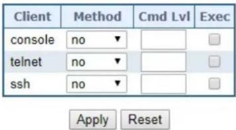
Figure 4-5-2-3: Authentication Method Configuration Page Screenshot
The page includes the following fields:
Authentication Method Configuration
The authentication section allows you to configure how a user is authenticated when he logs into the switch via one of the management client interfaces.
The table has one row for each client type and a number of columns, which are:
| Object Description | |
| • Client | The management client for which the configuration below applies. |
| • Methods | Method can be set to one of the following values:no: Authentication is disabled and login is not possible.local: Use the local user database on the switch for authentication.radius: Use remote RADIUS server(s) for authentication.tacacs: Use remote TACACS+ server(s) for authentication.. |
Command Authorization Method Configuration
The command authorization section allows you to limit the CLI commands available to a user.
The table has one row for each client type and a number of columns, which are:
| Object Description | |
| • Client | The management client for which the configuration below applies. |
| • Methods | Method can be set to one of the following values:no: Command authorization is disabled. User is granted access to CLI commands according to his privilege level.tacacs: Use remoteTACACS+server(s) for command authorization. If all remote servers are offline, the user is granted access to CLI commands according to his privilege leve |
| • Cmd Lvl | Authorize all commands with a privilege level higher than or equal to this level. Valid values are in the range 0 to 15. |
| • Cfg Cmd | Also authorize configuration commands |
Accounting Method Configuration
The accounting section allows you to configure command and exec (login) accounting.
The table has one row for each client type and a number of columns, which are:
| Object Description | |
| Client | The management client for which the configuration below applies. |
| Methods | Method can be set to one of the following values:no: Accounting is disabled.tacacs: Use remoteTACACS+server(s) for accounting. |
| Cmd Lvl | Enable accounting of all commands with a privilege level higher than or equal to this level.Valid values are in the range 0 to 15. Leave the field empty to disable command accounting. |
| • Exec | Enable exec (login) accounting. |
Buttons

: Click to apply changes

: Click to undo any changes made locally and revert to previously saved values.
4.5.2.2 RADIUS
This page allows you to configure the RADIUS Servers. The RADIUS Configuration screen in Figure 4-5-2-4 appears.
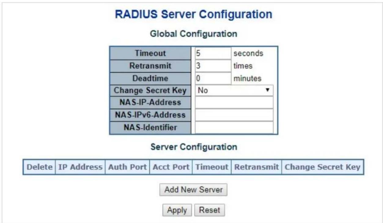
Figure 4-5-2-4: RADIUS Server Configuration Page Screenshot
The page includes the following fields:
Global Configuration
These setting are common for all of the RADIUS Servers.
| Object Description | |
| Timeout | Timeout is the number of seconds, in the range 1 to 1000, to wait for a reply from a RADIUS server before retransmitting the request. |
| Retransmit | Retransmit is the number of times, in the range from 1 to 1000; a RADIUS request is retransmitted to a server that is not responding. If the server has not responded after the last retransmit, it is considered to be dead. |
| Dead Time | The Dead Time, which can be set to a number between 0 and 3600 seconds, is the period during which the switch will not send new requests to a server that hasfailed to respond to a previous request. This will stop the switch from continually trying to contact a server that it has already determined as dead.Setting the Dead Time to a value greater than 0 (zero) will enable this feature, but only if more than one server has been configured. |
| • Key | The secret key - up to 63 characters long - shared between the RADIUS server and the switch. |
| • NAS-IP-Address | The IPv4 address to be used as attribute 4 in RADIUS Access-Request packets.If this field is left blank, the IP address of the outgoing interface is used. |
| • NAS-IPv6-Address | The IPv6 address to be used as attribute 95 in RADIUS Access-Request packets. If this field is left blank, the IP address of the outgoing interface is used. |
| • NAS-Identifier | The identifier - up to 253 characters long - to be used as attribute 32 in RADIUS Access-Request packets. If this field is left blank, the NAS-Identifier is not included in the packet. |
Server Configuration
The table has one row for each RADIUS Server and a number of columns, which are:
| Object Description | |
| Delete | To delete a RADIUS server entry, check this box. The entry will be deleted during the next Save. |
| Hostname | The IP address or hostname of the RADIUS server. |
| Auth Port | The UDP port to use on the RADIUS server for authentication. |
| Acct Port | The UDP port to use on the RADIUS server for accounting. |
| Timeout | This optional setting overrides the global timeout value. Leaving it blank will use the global timeout value. |
| Retransmit | This optional setting overrides the global retransmit value. Leaving it blank will use the global retransmit value. |
| Key | This optional setting overrides the global key. Leaving it blank will use the global key. |
Buttons
Add New Server
Click to add a new RADIUS server. An empty row is added to the table, and the RADIUS server can be configured as needed. Up to 5 servers are supported.
Delete
: Click to undo the addition of the new server.
Apply
: Click to apply changes
Reset
: Click to undo any changes made locally and revert to previously saved values.
4.5.2.3 TACACS+
This page allows you to configure the TACACS+ Servers. The TACACS+ Configuration screen in Figure 4-5-2-5 appears.
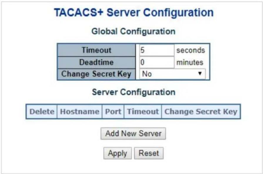
Figure 4-5-2-5: TACACS+ Server Configuration Page Screenshot
The page includes the following fields:
Global Configuration
These setting are common for all of the TACACS+ Servers.
| Object Description | |
| Timeout | Timeout is the number of seconds, in the range 1 to 1000, to wait for a reply from a TACACS+ server before it is considered to be dead. |
| Dead Time | The Dead Time, which can be set to a number between 0 to 1440 minutes, is the period during which the switch will not send new requests to a server that has failed to respond to a previous request. This will stop the switch from continually trying to contact a server that it has already determined as dead.Setting the Dead Time to a value greater than 0 (zero) will enable this feature, but only if more than one server has been configured. |
| Key | Specify to change the secret key or not. When "Yes" is selected for the option, you can change the secret key - up to 63 characters long - shared between the TACACS+ server and the switch. |
Server Configuration
The table has one row for each TACACS+ server and a number of columns, which are:
| Object Description | |
| Delete | To delete a TACACS+ server entry, check this box. The entry will be deleted during the next Save. |
| Hostname | The IP address or hostname of the TACACS+ server. |
| Port | The TCP port to use on the TACACS+ server for authentication. |
| Timeout | This optional setting overrides the global timeout value. Leaving it blank will use the global timeout value. |
| Key | This optional setting overrides the global key. Leaving it blank will use the global key. |
Buttons
Add New Server
Click to add a new TACACS+ server. An empty row is added to the table, and the
TACACS+ server can be configured as needed. Up to 5 servers are supported.
Delete
Click to undo the addition of the new server.
Apply
: Click to apply changes
Reset
: Click to undo any changes made locally and revert to previously saved values.
4.5.2.4 RADIUS Overview
This page provides an overview of the status of the RADIUS servers configurable on the authentication configuration page. The RADIUS Authentication/Accounting Server Overview screen in Figure 4-5-2-6 appears.
RADIUS Server Status Overview
| # | IP Address | Authentication Port | Authentication Status | Accounting Port | Accounting Status |
| 1/2345 | Disabled | Disabled | |||
| Disabled | Disabled | ||||
| Disabled | Disabled | ||||
| Disabled | Disabled | ||||
| Disabled | Disabled | ||||
Auto-refresh ☐ Refresh
Figure 4-5-2-6: RADIUS Authentication/Accounting Server Overview Page Screenshot
The page includes the following fields:
RADIUS Authentication Server Status Overview
| Object Description | |
| # | The RADIUS server number. Click to navigate to detailed statistics for this server. |
| IP Address | The IP address and UDP port number (in: notation) of this server. |
| Authentication Port | UDP port number for authentication. |
| Authentication Status | The current status of the server. This field takes one of the following values:Disabled: The server is disabled.Not Ready: The server is enabled, but IP communication is not yet up and running.Ready: The server is enabled, IP communication is up and running, and the RADIUS module is ready to accept access attempts.Dead (X seconds left): Access attempts were made to this server, but it did not reply within the configured timeout. The server has temporarily been disabled, but will get re-enabled when the dead-time expires. The number of seconds left before this occurs is displayed in parentheses. This state is only reachable when more than one server is enabled. |
| Accounting Port | UDP port number for accounting |
| Accounting Status | The current status of the server. This field takes one of the following values:Disabled: The server is disabled.Not Ready: The server is enabled, but IP communication is not yet up and running.Ready: The server is enabled, IP communication is up and running, and the RADIUS module is ready to accept access attempts.Dead (X seconds left): Access attempts were made to this server, but it did not reply withinthe configured timeout. The server has temporarily been disabled, but will get re-enabled when the dead-time expires. The number of seconds left before this occurs is displayed in parentheses. This state is only reachable when more than one server is enabled. |
Buttons
Auto-refresh ☐: Check this box to refresh the page automatically. Automatic refresh occurs every 3 seconds.
Refresh
Click to refresh the page immediately.
4.5.2.5 RADIUS Details
This page provides detailed statistics for a particular RADIUS server. The RADIUS Authentication/Accounting for Server Overview screen in Figure 4-5-2-7 appears.
RADIUS Authentication Statistics for Server #1
| Server #1 | |||
| Receive Packets | Transmit Packets | ||
| Access Accepts | 0 | Access Requests | 0 |
| Access Rejects | 0 | Access Retransmissions | 0 |
| Access Challenges | 0 | Pending Requests | 0 |
| Malformed Access Responses | 0 | Timeouts | 0 |
| Bad Authenticators | 0 | ||
| Unknown Types | 0 | ||
| Packets Dropped | 0 | ||
| Other Info | |||
| IP Address | 0.0.0.0.0 | ||
| State | Disabled | ||
| Round-Trip Time | 0 ms | ||
RADIUS Accounting Statistics for Server #1
| Receive Packets | Transmit Packets | ||
| Responses | 0 | Requests | 0 |
| Malformed Responses | 0 | Retransmissions | 0 |
| Bad Authenticators | 0 | Pending Requests | 0 |
| Unknown Types | 0 | Timeouts | 0 |
| Packets Dropped | 0 | ||
| Other Info | |||
| IP Address | 0.0.0.0:0 | ||
| State | Disabled | ||
| Round-Trip Time | 0 ms | ||
| Auto-refresh ☐ Refresh Clear | |||
Figure 4-5-2-7: RADIUS Authentication/Accounting for Server Overview Screenshot
The page includes the following fields:
RADIUS Authentication Statistics
The statistics map closely to those specified in RFC4668 - RADIUS Authentication Client MIB. Use the server select box to switch between the backend servers to show details for.
| Object Description | ||||
| Packet Counters | RADIUS authentication server packet counter. There are seven receive and four transmit counters. | |||
| Direction | Name | RFC4668 Name | Description | |
| Rx Access | Accepts | radiusAuthClientExtAccessAccepts | The number of RADIUS Access-Accept packets (valid or invalid) received from the server. | |
| Rx | Access Rejects | radiusAuthClientExtAccessRejects | The number of RADIUS Access-Reject packets (valid or invalid) received from the server. | |
| Rx Access | Challenges | radiusAuthClientExtAccessChallenges | The number of RADIUS Access-Challenge packets (valid or invalid) received from the server. | |
| Rx Malformed | AccessResponses | radiusAuthClientExtMalformedAccessResponses | The number of malformed RADIUS Access-Response packets received from the server. Malformed packets include packets with an invalid length. Bad authenticators or Message Authenticator attributes or unknown types are not included as malformed access responses. | |
| Rx Bad | Authenticators | radiusAuthClientExtBadAuthenticators | The number of RADIUS Access-Response packets containing invalid authenticators or Message Authenticator attributes received from the server. | |
| Rx Unknown | Types | radiusAuthClientExtUnknownTypes | The number of RADIUS packets that were received from the server on the authentication port and dropped for some other | |
| reason. | |||
| Rx Packets | Dropped | radiusAuthClientExtP packetsDropped | The number of RADIUS packets that were received from the server on the authentication port and dropped for some other reason. |
| Tx Access | Requests | radiusAuthClientExtA cccessRequests | The number of RADIUS Access-Request packets sent to the server. This does not include retransmissions. |
| Tx Access | Retransmissio ns | radiusAuthClientExtA cccessRetransmission s | The number of RADIUS Access-Request packets retransmitted to the RADIUS authentication server. |
| Tx Pending | Requests | radiusAuthClientExtP endingRequests | The number of RADIUS Access-Request packets destined for the server that have not yet timed out or received a response. This variable is incremented when an Access-Request is sent and decremented due to receipt of an Access-Accept, Access-Reject, Access-Challenge, timeout, or retransmission. |
| Tx | Timeouts | radiusAuthClientExtT timeouts | The number of authentication timeouts to the server. After a timeout, the client may retry to the same server, send to a different server, or give up. A retry to the same server is counted as a retransmit as well as a timeout. A send to a different server is counted as a Request as well as a timeout. |
| • Other Info | This section contains information about the state of the server and the latest round-trip time. | ||
| Name | RFC4668 Name | Description | |
| IP Address | - | IP address and UDP port for the authentication server in question. | |
| State | - | Shows the state of the server. It takes one of the following values:■Disabled:The selected server is disabled.■Not Ready:The server is enabled, but IP communication is not yet up and running.■Ready:The server is enabled, IP communication is up and running, and the RADIUS module is ready to accept access attempts.■Dead (X seconds left):Access attempts were made to this server, but it did not reply within the configured timeout. The server has temporarily been disabled, but will get re-enabled when the dead-time expires. The number of seconds left before this occurs is displayed in parentheses. This state is only reachable when more than one server is enabled. | |
| Round-Trip Time | radiusAuthClientExtRoundTripTime | The time interval (measured in milliseconds) between the most recent Access-Reply/Access-Challenge and the Access-Request that matched it from the RADIUS authentication server. The granularity of this measurement is 100 ms. A value of 0 ms indicates that there hasn't been round-trip communication with the server yet. | |
RADIUS Accounting Statistics
The statistics map closely to those specified in RFC4670 - RADIUS Accounting Client MIB. Use the server select box to switch between the backend servers to show details for.
| Object Description | ||||
| • Packet Counters | RADIUS accounting server packet counter. There are five receive and four transmit counters. | |||
| Direction | Name | RFC4670 Name | Description | |
| Rx | Responses | radiusAccClientExt | The number of RADIUS packets (valid or invalid) | |
| Responses | received from the server. | ||
| Rx MalformedResponses | radiusAccClientExtMalformedResponses | The number of malformed RADIUS packets received from the server. Malformed packets include packets with an invalid length. Bad authenticators or unknown types are not included as malformed access responses. | |
| Rx BadAuthenticators | radiusAcctClientExtBadAuthenticators | The number of RADIUS packets containing invalid authenticators received from the server. | |
| Rx | Unknown Types | radiusAccClientExtUnknownTypes | The number of RADIUS packets of unknown types that were received from the server on the accounting port. |
| Rx | Packets Dropped | radiusAccClientExtPacketsDropped | The number of RADIUS packets that were received from the server on the accounting port and dropped for some other reason. |
| Tx | Requests | radiusAccClientExtRequests | The number of RADIUS packets sent to the server. This does not include retransmissions. |
| Tx | Retransmissions | radiusAccClientExtRetransmissions | The number of RADIUS packets retransmitted to the RADIUS accounting server. |
| Tx PendingRequests | radiusAccClientExtPendingRequests | The number of RADIUS packets destined for the server that have not yet timed out or received a response. This variable is incremented when a Request is sent and decremented due to receipt of a Response, timeout, or | |
| retransmission. | |||
| TxTimeoutsradiusAccClientExtTimeouts | The number of accounting timeouts to the server. After a timeout, the client may retry to the same server, send to a different server, or give up. A retry to the same server is counted as a retransmit as well as a timeout. A send to a different server is counted as a Request as well as a timeout. | ||
| • Other Info | This section contains information about the state of the server and the latest round-trip time. | ||
| Name | RFC4670 Name | Description | |
| IP Address | - | IP address and UDP port for the accounting server in question. | |
| State | - | Shows the state of the server. It takes one of the following values:■Disabled:The selected server is disabled.■Not Ready:The server is enabled, but IP communication is not yet up and running.■Ready:The server is enabled, IP communication is up and running, and the RADIUS module is ready to accept accounting attempts.■Dead (X seconds left): Accounting attempts were made to this server, but it did not reply within the configured timeout. The server has temporarily been disabled, but will get re-enabled when the dead-time expires. The number of seconds left before this occurs is displayed in parentheses. This state is only reachable when more than one server is enabled. | |
| Round-Trip Time | radiusAccClientExtRo undTripTime | ■The time interval (measured in milliseconds) between the most recent Response and the Request that matched it from the RADIUS accounting server. The granularity of this measurement is | |
100 ms. A value of 0 ms indicates that
there hasn't been round-trip
communication with the server yet.
Buttons
Auto-refresh ☐: Check this box to refresh the page automatically. Automatic refresh occurs every 3 seconds.
Refresh
Click to refresh the page immediately.
Clear
: Clears the counters for the selected server. The "Pending Requests" counter will not be cleared by this operation.
4.5.3 Port Authentication
4.5.3.1 Network Access Server Configuration
This page allows you to configure the IEEE 802.1X and MAC-based authentication system and port settings.
The IEEE 802.1X standard defines a port-based access control procedure that prevents unauthorized access to a network by requiring users to first submit credentials for authentication. One or more central servers, the backend servers, determine whether the user is allowed access to the network. These backend (RADIUS) servers are configured on the
"Configuration→Security→AAA" Page. The IEEE802.1X standard defines port-based operation, but non-standard variants overcome security limitations as shall be explored below.
MAC-based authentication allows for authentication of more than one user on the same port, and doesn't require the user to have special 802.1X supplicant software installed on his system. The switch uses the user's MAC address to authenticate against the backend server. Intruders can create counterfeit MAC addresses, which makes MAC-based authentication less secure than 802.1X authentication. The NAS configuration consists of two sections, a system- and a port-wide. The Network Access Server Configuration screen in Figure 4-5-3-1 appears.
Network Access Server Configuration
System Configuration
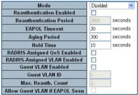
Port Configuration
| Port | Admin State | RADIUS-Assigned QoS Enabled | RADIUS-Assigned VLAN Enabled | Guest VLAN Enabled | Port State | Restart | |
| * | |||||||
| 1 | Force Authorized | Globally Disabled | Reauthenticate | Reinitialize | |||
| 2 | Force Authorized | Globally Disabled | Reauthenticate | Reinitialize | |||
| 3 | Force Authorized | Globally Disabled | Reauthenticate | Reinitialize | |||
| 4 | Force Authorized | Globally Disabled | Reauthenticate | Reinitialize | |||
| 5 | Force Authorized | Globally Disabled | Reauthenticate | Reinitialize | |||
| 6 | Force Authorized | Globally Disabled | Reauthenticate | Reinitialize | |||
| 7 | Force Authorized | Globally Disabled | Reauthenticate | Reinitialize | |||
| 8 | Force Authorized | Globally Disabled | Reauthenticate | Reinitialize | |||
Figure 4-5-3-1: Network Access Server Configuration Page Screenshot
The page includes the following fields:
System Configuration
| Object Description | |
| • Mode | Indicates if NAS is globally enabled or disabled on the switch. If globally disabled, all ports are allowed forwarding of frames. |
| • Reauthentication Enabled | If checked, successfully authenticated supplicants/clients are reauthenticated after the interval specified by the Reauthentication Period. Reauthentication for 802.1X-enabled ports can be used to detect if a new device is plugged into a switch port or if a supplicant is no longer attached.For MAC-based ports, reauthentication is only useful if the RADIUS server configuration has changed. It does not involve communication between the switch and the client, and therefore doesn't imply that a client is still present on a port. |
| • Reauthentication Period | Determines the period, in seconds, after which a connected client must be reauthenticated. This is only active if the Reauthentication Enabled checkbox is checked. Valid values are in the range 1 to 3600 seconds. |
| • EAPOL Timeout | Determines the time for retransmission of Request Identity EAPOL frames. Valid values are in the range 1 to 65535 seconds. This has no effect for MAC-based ports. |
| • Aging Period | This setting applies to the following modes, i.e. modes using the Port Security functionality to secure MAC addresses:■ Single 802.1X■ Multi 802.1X■ MAC-Based Auth.When the NAS module uses the Port Security module to secure MAC addresses, the Port Security module needs to check for activity on the MAC address in question at regular intervals and free resources if no activity is seen within a given period of time. This parameter controls exactly this period and can be set to a number between 10 and 1000000 seconds.If reauthentication is enabled and the port is in a 802.1X-based mode, this is not so critical, since supplicants that are no longer attached to the port will get removed upon the next reauthentication, which will fail. But if reauthentication is not enabled, the only way to free resources is by aging the entries.For ports in MAC-based Auth. mode, reauthentication doesn't cause direct communication between the switch and the client, so this will not detect whether the client is still attached or not, and the only way to free any resources is to agethe entry. |
| Hold Time | This setting applies to the following modes, i.e. modes using the Port Security functionality to secure MAC addresses:Single 802.1XMulti 802.1XMAC-Based Auth.If a client is denied access, either because the RADIUS server denies the client access or because the RADIUS server request times out (according to the timeout specified on the "Configuration→Security→AAA" page), the client is put on hold in the Unauthorized state. The hold timer does not count during an on-going authentication.In MAC-based Auth. mode, the switch will ignore new frames coming from the client during the hold time.The Hold Time can be set to a number between 10 and 1000000 seconds. |
| RADIUS-Assigned QoS Enabled | RADIUS-assigned QoS provides a means to centrally control the traffic class to which traffic coming from a successfully authenticated supplicant is assigned on the switch. The RADIUS server must be configured to transmit special RADIUS attributes to take advantage of this feature.The "RADIUS-Assigned QoS Enabled" checkbox provides a quick way to globally enable/disable RADIUS-server assigned QoS Class functionality. When checked, the individual ports' ditto setting determines whether RADIUS-assigned QoS Class is enabled for that port. When unchecked, RADIUS-server assigned QoS Class is disabled for all ports. |
| RADIUS-Assigned VLAN Enabled | RADIUS-assigned VLAN provides a means to centrally control the VLAN on which a successfully authenticated supplicant is placed on the switch. Incoming traffic will be classified to and switched on the RADIUS-assigned VLAN. The RADIUS server must be configured to transmit special RADIUS attributes to take advantage of this feature.The "RADIUS-Assigned VLAN Enabled" checkbox provides a quick way to globally enable/disable RADIUS-server assigned VLAN functionality. When checked, the individual ports' ditto setting determines whether RADIUS-assigned VLAN is enabled for that port. When unchecked, RADIUS-server assigned VLAN is disabled for all ports. |
| Guest VLAN Enabled | A Guest VLAN is a special VLAN - typically with limited network access - on which 802.1X-unaware clients are placed after a network administrator-defined timeout. The switch follows a set of rules for entering and leaving the GuestVLAN as listed below.The "Guest VLAN Enabled" checkbox provides a quick way to globally enable/disable Guest VLAN functionality. When checked, the individual ports' ditto setting determines whether the port can be moved into Guest VLAN. When unchecked, the ability to move to the Guest VLAN is disabled for all ports. |
| • Guest VLAN ID | This is the value that a port's Port VLAN ID is set to if a port is moved into the Guest VLAN. It is only changeable if the Guest VLAN option is globally enabled.Valid values are in the range [1; 4095]. |
| • Max. Reauth. Count | The number of times that the switch transmits an EAPOL Request Identity frame without response before considering entering the Guest VLAN is adjusted with this setting. The value can only be changed if the Guest VLAN option is globally enabled.Valid values are in the range [1; 255]. |
| • Allow Guest VLAN if EAPOL Seen | The switch remembers if an EAPOL frame has been received on the port for the life-time of the port. Once the switch considers whether to enter the Guest VLAN, it will first check if this option is enabled or disabled. If disabled (unchecked; default), the switch will only enter the Guest VLAN if an EAPOL frame has not been received on the port for the life-time of the port. If enabled (checked), the switch will consider entering the Guest VLAN even if an EAPOL frame has been received on the port for the life-time of the port.The value can only be changed if the Guest VLAN option is globally enabled. |
Buttons
Refresh
Click to refresh the page immediately.
Apply
Click to apply changes
Reset
Click to undo any changes made locally and revert to previously saved values.
4.5.3.2 Network Access Overview
This page provides an overview of the current NAS port states for the selected switch. The Network Access Overview screen in Figure 4-5-3-2 appears.
Network Access Server Switch Status
| Port | Admin State | Port State | Last Source | Last ID | QoS Class | Port VLAN ID |
| 1 | Force Authorized | Globally Disabled | - | |||
| 2 | Force Authorized | Globally Disabled | - | |||
| 3 | Force Authorized | Globally Disabled | - | |||
| 4 | Force Authorized | Globally Disabled | - | |||
| 5 | Force Authorized | Globally Disabled | - | |||
| 6 | Force Authorized | Globally Disabled | - | |||
| 7 | Force Authorized | Globally Disabled | - | |||
| 8 | Force Authorized | Globally Disabled | - |
Figure 4-5-3-2: Network Access Server Switch Status Page Screenshot
The page includes the following fields:
| Object Description | |
| • Port | The switch port number. Click to navigate to detailed NAS statistics for this port. |
| • Admin State | The port's current administrative state. Refer to NAS Admin State for a description of possible values. |
| • Port State | The current state of the port. Refer to NAS Port State for a description of the individual states. |
| • Last Source | The source MAC address carried in the most recently received EAPOL frame for EAPOL-based authentication, and the most recently received frame from a new client for MAC-based authentication. |
| • Last ID | The user name (supplicant identity) carried in the most recently received Response Identity EAPOL frame for EAPOL-based authentication, and the source MAC address from the most recently received frame from a new client for MAC-based authentication. |
| • QoS Class | QoS Class assigned to the port by the RADIUS server if enabled. |
| • Port VLAN ID | The VLAN ID that NAS has put the port in. The field is blank, if the Port VLAN ID is not overridden by NAS.If the VLAN ID is assigned by the RADIUS server,"(RADIUS-assigned)" is appended to the VLAN ID. Read moreabout RADIUS-assigned VLANs here.If the port is moved to the Guest VLAN, "(Guest)" is appended to the VLAN ID. Read more about Guest VLANs here. |
Buttons
Auto-refresh ☐: Check this box to refresh the page automatically. Automatic refresh occurs every 3 seconds.
Refresh: Click to refresh the page immediately.
4.5.3.3 Network Access Statistics
This page provides detailed NAS statistics for a specific switch port running EAPOL-based IEEE 802.1X authentication. For MAC-based ports, it shows selected backend server (RADIUS Authentication Server) statistics, only. Use the port select box to select which port details to be displayed. The Network Access Statistics screen in Figure 4-5-3-3 appears.
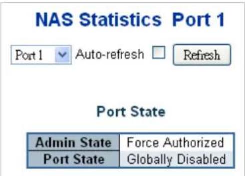
Figure 4-5-3-3: Network Access Statistics Page Screenshot
The page includes the following fields:
Port State
| Object Description | |
| • Admin State | The port's current administrative state. Refer to NAS Admin State for a description of possible values. |
| • Port State | The current state of the port. Refer to NAS Port State for a description of the individual states. |
| • QoS Class | The QoS class assigned by the RADIUS server. The field is blank if no QoS class is assigned. |
| • Port VLAN ID | The VLAN ID that NAS has put the port in. The field is blank, if the Port VLAN ID is not overridden by NAS.If the VLAN ID is assigned by the RADIUS server, "(RADIUS-assigned)" is appended to the VLAN ID. Read more about RADIUS-assigned VLANs here.If the port is moved to the Guest VLAN, "(Guest)" is appended to the VLAN ID.Read more about Guest VLANs here. |
Port Counters
| Object Description | ||||
| • EAPOL Counters | These supplicant frame counters are available for the following administrative states:■ Force Authorized■ Force Unauthorized■ Port-based 802.1X■ Single 802.1X■ Multi 802.1X | |||
| Direction | Name | IEEE Name | Description | |
| Rx | Total | dot1xAuthEapolFramesRx | The number of valid EAPOL frames of any type that have been received by the switch. | |
| Rx | Response ID | dot1xAuthEapolRespId FramesRx | The number of valid EAPOL Response Identity frames that have been received by the switch. | |
| Rx | Responses | dot1xAuthEapolRespFramesRx | The number of valid EAPOL response frames (other than Response Identity frames) that have been received by the switch. | |
| Rx | Start | dot1xAuthEapolStartFramesRx | The number of EAPOL Start frames that have been received by the switch. | |
| Rx | Logoff | dot1xAuthEapolLogoffFramesRx | The number of valid EAPOL Logoff frames that have been received by the switch. | |
| Rx | Invalid Type | dot1xAuthInvalidEapolFramesRx | The number of EAPOL frames that have been received by the switch in which the frame type is not recognized. | |
| Rx | Invalid Length | dot1xAuthEapLengthErrorFramesRx | The number of EAPOL frames that have been received by the switch in which the Packet BodyLength field is invalid. | |
| Tx | Total | dot1xAuthEapolFrames Tx | The number of EAPOL frames of any type that have been transmitted by the switch. | |
| Tx | Request ID | dot1xAuthEapolReqIdFramesTx | The number of EAPOL Request Identity frames that have been transmitted by the switch. | |
| Tx | Requests | dot1xAuthEapolReqFramesTx | The number of valid EAPOL Request frames (other than Request Identity frames) that have been transmitted by the switch. | |
| • Backend Server Counters | These backend (RADIUS) frame counters are available for the following administrative states:■ Port-based 802.1X■ Single 802.1X■ Multi 802.1X■ MAC-based Auth. | |||
| Direction | Name | IEEE Name | Description | |
| Rx AccessChallenges | dot1xAuthBackendAccessChallenges | 802.1X-based:Counts the number of times that the switch receives the first request from the backend server following the first response from the supplicant. Indicates that the backend server has communication with the switch.MAC-based:Counts all Access Challenges received from the backend server for this port (left-most table) or client (right-most table). | ||
| Rx | Other | dot1xAuthBackendOther | 802.1X-based: | |
| Requests | RequestsToSupplicant | Counts the number of times that the switch sends an EAP Request packet following the first to the supplicant. Indicates that the backend server chose an EAP-method. MAC-based: Not applicable. | |
| Rx Auth. | Successes | dot1xAuthBackendAuth Successes | 802.1X- and MAC-based: Counts the number of times that the switch receives a success indication. Indicates that the supplicant/client has successfully authenticated to the backend server. |
| Rx Auth. | Failures | dot1xAuthBackendAuth Fails | 802.1X- and MAC-based: Counts the number of times that the switch receives a failure message. This indicates that the supplicant/client has not authenticated to the backend server. |
| Tx | Responses | dot1xAuthBackendResp onses | 802.1X-based: Counts the number of times that the switch attempts to send a supplicant's first response packet to the backend server. Indicates the switch attempted communication with the backend server. Possible retransmissions are not counted. MAC-based: Counts all the backend server packets sent from the switch towards the backend server for a given port (left-most table) or client (right-most |
| table). Possible retransmissions are not counted. | ||
| • Last Supplicant/Client Info | Information about the last supplicant/client that attempted to authenticate. This information is available for the following administrative states:■ Port-based 802.1X■ Single 802.1X■ Multi 802.1X■ MAC-based Auth. | |
| Name IEEE | Name Description | |
| MAC Address | dot1xAuthLastEapolF rameSource | |
| VLAN ID | - | |
| Version | dot1xAuthLastEapolF rameVersion | |
| Identity | - | |
Buttons
Auto-refresh ☐: Check this box to refresh the page automatically. Automatic refresh occurs every 3 seconds.
Refresh
Click to refresh the page immediately.
4.5.4 Port Security
4.5.4.1 Port Limit Control
This page allows you to configure the Port Security global and per-port settings.
Port Security allows for limiting the number of users on a given port. A user is identified by a MAC address and VLAN ID. If Port Security is enabled on a port, the limit specifies the maximum number of users on the port. If this number is exceeded, an action is taken depending on violation mode. The violation mode can be one of the four different described below.
The Port Security configuration consists of two sections, a global and a per-port.. The Port Limit Control Configuration screen in Figure 4-5-4-1 appears.
Port Security Configuration
Global Configuration
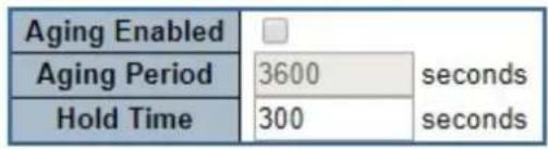
Port Configuration
| Port | Mode | Limit | Violation Mode | Violation Limit | State | ||
| * | 4 | 4 | |||||
| 1 | Disabled ▼ | 4 | Protect ▼ | 4 | Disabled | ||
| 2 | Disabled ▼ | 4 | Protect ▼ | 4 | Disabled | ||
| 3 | Disabled ▼ | 4 | Protect ▼ | 4 | Disabled | ||
| 4 | Disabled ▼ | 4 | Protect ▼ | 4 | Disabled | ||
| 5 | Disabled ▼ | 4 | Protect ▼ | 4 | Disabled | ||
| 6 | Disabled ▼ | 4 | Protect ▼ | 4 | Disabled | ||
| 7 | Disabled ▼ | 4 | Protect ▼ | 4 | Disabled | ||
| 8 | Disabled ▼ | 4 | Protect ▼ | 4 | Disabled | ||
| 9 | Disabled ▼ | 4 | Protect ▼ | 4 | Disabled | ||
| 10 | Disabled ▼ | 4 | Protect ▼ | 4 | Disabled | ||

Figure 4-5-4-1: Port Limit Control Configuration Overview Page Screenshot
The page includes the following fields:
System Configuration
| Object Description | |
| • Aging Enabled | If checked, secured MAC addresses are subject to aging as discussed under Aging Period . |
| • Aging Period | If Aging Enabled is checked, then the aging period is controlled with this input. If other modules are using the underlying port security for securing MACaddresses, they may have other requirements to the aging period. The underlying port security will use the shorter requested aging period of all modules that use the functionality.The Aging Period can be set to a number between 10 and 10,000,000 seconds.To understand why aging may be desired, consider the following scenario:Suppose an end-host is connected to a 3rd party switch or hub, which in turn is connected to a port on this switch on which Limit Control is enabled. The end-host will be allowed to forward if the limit is not exceeded. Now suppose that the end-host logs off or powers down. If it wasn't for aging, the end-host would still take up resources on this switch and will be allowed to forward. To overcome this situation, enable aging. With aging enabled, a timer is started once the end-host gets secured. When the timer expires, the switch starts looking for frames from the end-host, and if such frames are not seen within the next Aging Period, the end-host is assumed to be disconnected, and the corresponding resources are freed on the switch. |
| • Hold Time | The hold time - measured in seconds - is used to determine how long a MAC address is held in the MAC table if it has been found to violate the limit. Valid range is between 10 and 10000000 seconds with a default of 300 seconds.The reason for holding a violating MAC address in the MAC table is primarily to ensure that the same MAC address doesn't give rise to continuous notifications (if notifications on violation count is enabled). |
Port Configuration
The table has one row for each port and a number of columns, which are:
| Object Description | |
| • Port | The port number for which the configuration below applies. |
| • Mode | Controls whether Limit Control is enabled on this port. Both this and the Global Mode must be set to Enabled for Limit Control to be in effect. Notice that other modules may still use the underlying port security features without enabling Limit Control on a given port. |
| • Limit | The maximum number of MAC addresses that can be secured on this port. This number cannot exceed 1024. If the limit is exceeded, the corresponding action is taken.The switch is "born" with a total number of MAC addresses from which all ports draw whenever a new MAC address is seen on a Port Security-enabled port.Since all ports draw from the same pool, it may happen that a configured maximum cannot be granted, if the remaining ports have already used allavailable MAC addresses. |
| Violation Mode | If Limit is reached, the switch can take one of the following actions:Protect: Do not allow more than Limit MAC addresses on the port, but take no further action.Restrict: If Limit is reached, subsequent MAC addresses on the port will be counted and marked as violating. Such MAC addresses are removed from the MAC table when the hold time expires. At most Violation Limit MAC addresses can be marked as violating at any given time.Shutdown: If Limit is reached, one additional MAC address will cause the port to be shut down. This implies that all secured MAC addresses be removed from the port, and no new addresses be learned. There are three ways to re-open the port:In the "Configuration→Ports" page's "Configured" column, first disable the port, then restore the original mode.Make a Port Security configuration change on the port.Boot the switch. |
| Violation Limit | The maximum number of MAC addresses that can be marked as violating on this port. This number cannot exceed 1024. Default is 4. It is only used whenViolation Modeis Restrict. |
| State | This column shows the current state of the port as seen from the Limit Control's point of view. The state takes one of four values:Disabled: Limit Control is either globally disabled or disabled on the port.Ready: The limit is not yet reached. This can be shown for all actions.Limit Reached: Indicates that the limit is reached on this port. This state can only be shown if Action is set to None or Trap.Shutdown: Indicates that the port is shut down by the Limit Control module. This state can only be shown if Action is set to Shutdown or Trap & Shutdown. |
Buttons
Apply
: Click to apply changes
Reset
: Click to undo any changes made locally and revert to previously saved values.
Refresh
Click to refresh the page. Note that non-committed changes will be lost.
4.5.4.2 Port Security Status
This page shows the Port Security status. Port Security is a module with no direct configuration. Configuration comes indirectly from other modules - the user modules. When a user module has enabled port security on a port, the port is set-up for software-based learning. In this mode, frames from unknown MAC addresses are passed on to the port security module, which in turn asks all user modules whether to allow this new MAC address to forward or block it. For a MAC address to be set in the forwarding state, all enabled user modules must unanimously agree on allowing the MAC address to forward. If only one chooses to block it, it will be blocked until that user module decides otherwise.
The status page is divided into two sections - one with a legend of user modules and one with the actual port status. The Port Security Status screen in Figure 4-5-4-2 appears.
Port Security Switch Status
User Module Legend
| User Module Name | Abbr |
| Port Security (Admin) | P |
| 802.1X | 8 |
| Voice VLAN | V |
Port Status
| Clear | Port | Users | Violation Mode | State | MAC Count | ||
| Current | Violating | Limit | |||||
| Clear | 1 | --- | Disabled | Disabled | - | - | - |
| Clear | 2 | --- | Disabled | Disabled | - | - | - |
| Clear | 3 | --- | Disabled | Disabled | - | - | - |
| Clear | 4 | --- | Disabled | Disabled | - | - | - |
| Clear | 5 | --- | Disabled | Disabled | - | - | - |
| Clear | 6 | --- | Disabled | Disabled | - | - | - |
| Clear | 7 | --- | Disabled | Disabled | - | - | - |
| Clear | 8 | --- | Disabled | Disabled | - | - | - |
| Clear | 9 | --- | Disabled | Disabled | - | - | - |
| Clear | 10 | --- | Disabled | Disabled | - | - | - |
Figure 4-5-4-2: Port Security Status Screen Page Screenshot
The page includes the following fields:
User Module Legend
The legend shows all user modules that may request Port Security services.
| Object Description | |
| User Module Name | The full name of a module that may request Port Security services. |
| Abbr | A one-letter abbreviation of the user module. This is used in the Users column in the port status table. |
Port Status
The table has one row for each port on the selected switch in the switch and a number of columns, which are:
| Object Description | |
| Clear | Click to remove all MAC addresses on all VLANs on this port. The button is only clickable if number of secured MAC addresses is non-zero. |
| Port | The port number for which the status applies. Click the port number to see the status for this particular port. |
| Users | Each of the user modules has a column that shows whether that module has enabled Port Security or not. A '-' means that the corresponding user module is not enabled, whereas a letter indicates that the user module abbreviated by that letter has enabled port security. |
| Violation Mode | Shows the configured Violation Mode of the port. It can take one of four values:Disabled: Port Security is not administratively enabled on this port.Protect: Port Security is administratively enabled in Protect mode.Restrict: Port Security is administratively enabled in Restrict mode.Shutdown: Port Security is administratively enabled in Shutdown mode. |
| State | Shows the current state of the port. It can take one of four values:■ Disabled: No user modules are currently using the Port Security service.■ Ready: The Port Security service is in use by at least one user module, and is awaiting frames from unknown MAC addresses to arrive.■ Limit Reached: The Port Security service is enabled by at least the Limit Control user module, and that module has indicated that the limit is reached and no more MAC addresses should be taken in.■ Shutdown: The Port Security service is enabled by at least the Limit Control user module, and that module has indicated that the limit is exceeded. No MAC addresses can be learned on the port until it is administratively re-opened on the Limit Control configuration web page. |
| MAC Count(Current, Limit) | The two columns indicate the number of currently learned MAC addresses (forwarding as well as blocked) and the maximum number of MAC addresses that can be learned on the port, respectively.If no user modules are enabled on the port, the Current column will show a dash (-).If the Limit Control user module is not enabled on the port, the Limit column will show a dash (-). |
Buttons
Auto-refresh ☐: Check this box to refresh the page automatically. Automatic refresh occurs every 3 seconds.
Refresh
Click to refresh the page immediately.
4.5.4.3 Port Security Detail
This page shows the MAC addresses secured by the Port Security module. Port Security is a module with no direct configuration. Configuration comes indirectly from other modules - the user modules. When a user module has enabled port security on a port, the port is set-up for software-based learning. In this mode, frames from unknown MAC addresses are passed on to the port security module, which in turn asks all user modules whether to allow this new MAC address to forward or block it. For a MAC address to be set in the forwarding state, all enabled user modules must unanimously agree on allowing the MAC address to forward. If only one chooses to block it, it will be blocked until that user module decides otherwise. The Port Security Detail screen in Figure 4-5-4-3 appears.
Port Security Port Status Port 1
Port 1 ▼ Auto-refresh □ Refresh
| Clear | VLAN ID | MAC Address | State | Age/Hold |
| No MAC addresses attached | ||||
Figure 4-5-4-3: Port Security Detail Screen Page Screenshot
The page includes the following fields:
| Object Description | |
| • MAC Address & VLAN ID | The MAC address and VLAN ID that is seen on this port. If no MAC addresses are learned, a single row stating "No MAC addresses attached" is displayed. |
| • State | Indicates whether the corresponding MAC address is blocked or forwarding. In the blocked state, it will not be allowed to transmit or receive traffic. |
| • Age/Hold | ● If at least one user module has decided to block this MAC address, it will stay in the blocked state until the hold time (measured in seconds) expires.● If all user modules have decided to allow this MAC address to forward, and aging is enabled, the Port Security module will periodically check that this MAC address still forwards traffic.● If the age period (measured in seconds) expires and no frames have been seen, the MAC address will be removed from the MAC table. Otherwise a new age period will begin.● If aging is disabled or a user module has decided to hold the MAC address indefinitely, a dash (-) will be shown. |
Buttons
Auto-refresh ☐: Check this box to refresh the page automatically. Automatic refresh occurs every 3 seconds.
Refresh
Click to refresh the page immediately.
4.5.5 Access Control Lists
ACL is an acronym for Access Control List. It is the list table of ACEs, containing access control entries that specify individual users or groups permitted or denied to specific traffic objects, such as a process or a program.
Each accessible traffic object contains an identifier to its ACL. The privileges determine whether there are specific traffic object access rights.
ACL implementations can be quite complex, for example, when the ACEs are prioritized for the various situation. In networking, the ACL refers to a list of service ports or network services that are available on a host or server, each with a list of hosts or servers permitted or denied to use the service. ACL can generally be configured to control inbound traffic, and in this context, they are similar to firewalls.
ACE is an acronym for Access Control Entry. It describes access permission associated with a particular ACE ID.
There are three ACE frame types (Ethernet Type, ARP, and IPv4) and two ACE actions (permit and deny). The ACE also contains many detailed, different parameter options that are available for individual application.
4.5.5.1 Access Control List Status
This page shows the ACL status by different ACL users. Each row describes the ACE that is defined. It is a conflict if a specific ACE is not applied to the hardware due to hardware limitations. The maximum number of ACEs is 512 on each switch. The Voice VLAN OUI Table screen in Figure 4-5-5-1 appears.
| User | ACE | Frame Type | Action | Rate Limiter | Mirror | CPU | Counter | Conflict |
| No entries | ||||||||
| Combined Auto-refresh Refresh | ||||||||
Figure 4-5-5-1: ACL Status Page Screenshot
The page includes the following fields:
| Object Description | |
| • User | Indicates the ACL user. |
| • ACE | Indicates the ACE ID on local switch. |
| • Frame Type | Indicates the frame type of the ACE. Possible values are:■ Any: The ACE will match any frame type.■ EType: The ACE will match Ethernet Type frames. Note that an Ethernet Type based ACE will not get matched by IP and ARP frames.■ ARP: The ACE will match ARP/RARP frames.■ IPv4: The ACE will match all IPv4 frames.■ IPv4/ICMP: The ACE will match IPv4 frames with ICMP protocol. ■ IPv4/UDP: The ACE will match IPv4 frames with UDP protocol. ■ IPv4/TCP: The ACE will match IPv4 frames with TCP protocol. ■ IPv4/Other: The ACE will match IPv4 frames, which are not ICMP/UDP/TCP. ■ IPv6: The ACE will match all IPv6 standard frames. |
| • Action | Indicates the forwarding action of the ACE. ■ Permit: Frames matching the ACE may be forwarded and learned. ■ Deny: Frames matching the ACE are dropped. |
| • Rate Limiter | Indicates the rate limiter number of the ACE. The allowed range is 1 to 16. When Disabled is displayed, the rate limiter operation is disabled. |
| • CPU | Forward packet that matched the specific ACE to CPU |
| • Counter | The counter indicates the number of times the ACE was hit by a frame. |
| • Conflict | Indicates the hardware status of the specific ACE. The specific ACE is not applied to the hardware due to hardware limitations. |
Buttons
Auto-refresh ☐: Check this box to refresh the page automatically. Automatic refresh occurs every 3 seconds.
Refresh
Click to refresh the page.
4.5.5.2 Access Control List Configuration
This page shows the Access Control List (ACL), which is made up of the ACEs defined on this switch. Each row describes the ACE that is defined. The maximum number of ACEs is 512 on each switch.
Click on the lowest plus sign to add a new ACE to the list. The reserved ACEs used for internal protocol, cannot be edited or deleted, the order sequence cannot be changed and the priority is highest. The Access Control List Configuration screen in
Figure 4-5-5-2 appears.

Figure 4-5-5-2: Access Control List Configuration Page Screenshot
The page includes the following fields:
| Object Description | |
| • ACE | Indicates the ACE ID. |
| • Ingress Port | Indicates the ingress port of the ACE. Possible values are:■ All: The ACE will match all ingress port.■ Port: The ACE will match a specific ingress port. |
| • Policy / Bitmask | Indicates the policy number and bitmask of the ACE. |
| • Frame Type | Indicates the frame type of the ACE. Possible values are:■ Any: The ACE will match any frame type.■ EType: The ACE will match Ethernet Type frames. Note that an Ethernet Type based ACE will not get matched by IP and ARP frames.■ ARP: The ACE will match ARP/RARP frames.■ IPv4: The ACE will match all IPv4 frames.■ IPv4/ICMP: The ACE will match IPv4 frames with ICMP protocol.■ IPv4/UDP: The ACE will match IPv4 frames with UDP protocol.■ IPv4/TCP: The ACE will match IPv4 frames with TCP protocol.■ IPv4/Other: The ACE will match IPv4 frames, which are not ICMP/UDP/TCP.■ IPv6: The ACE will match all IPv6 standard frames. |
| • Action | Indicates the forwarding action of the ACE.■ Permit: Frames matching the ACE may be forwarded and learned.■ Deny: Frames matching the ACE are dropped.■ Filter: Frames matching the ACE are filtered. |
| • Rate Limiter | Indicates the rate limiter number of the ACE. The allowed range is 1 to 16. When Disabled is displayed, the rate limiter operation is disabled. |
| • Port Redirect | Indicates the port redirect operation of the ACE. Frames matching the ACE are redirected to the port number.The allowed values areDisabledor a specific port number. WhenDisabledis displayed, the port redirect operation is disabled. |
| • Mirror | pecify the mirror operation of this port. Frames matching the ACE are mirrored to the destination mirror port. The allowed values are:Enabled: Frames received on the port are mirrored level. Disabled: Frames received on the port are not mirrored. The default value is "Disabled". |
| • Counter | The counter indicates the number of times the ACE was hit by a frame. |
| • Modification Buttons | You can modify each ACE (Access Control Entry) in the table using the following buttons:+: Inserts a new ACE before the current row.⊕: Edits the ACE row.↑: Moves the ACE up the list.↓: Moves the ACE down the list.✕: Deletes the ACE.⊕: The lowest plus sign adds a new entry at the bottom of the ACE listings. |
Buttons
Auto-refresh ☐: Check this box to refresh the page automatically. Automatic refresh occurs every 3 seconds.
Refresh
Click to refresh the page; any changes made locally will be undone.
Clear
: Click to clear the counters.
Remove All
Click to remove all ACEs.
4.5.5.3 ACE Configuration
Configure an ACE (Access Control Entry) on this page. An ACE consists of several parameters. These parameters vary according to the frame type that you select. First select the ingress port for the ACE, and then select the frame type. Different parameter options are displayed depending on the frame type selected. A frame that hits this ACE matches the configuration that is defined here. The ACE Configuration screen in Figure 4-5-5-3 appears.
ACE Configuration
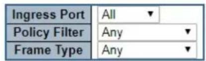
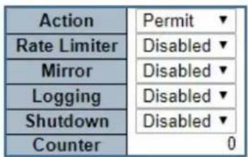
VLAN Parameters
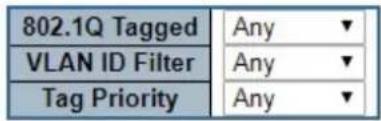

Figure 4-5-5-3: ACE Configuration Page Screenshot
The page includes the following fields:
| Object Description | |
| • Ingress Port | Select the ingress port for which this ACE applies.■ Any: The ACE applies to any port.■ Port n: The ACE applies to this port number, where n is the number of the switch port. |
| • Policy Filter | Specify the policy number filter for this ACE.■ Any: No policy filter is specified. (policy filter status is "don't-care".)■ Specific: If you want to filter a specific policy with this ACE, choose this value. Two field for entering an policy value and bitmask appears. |
| • Policy Value | When "Specific" is selected for the policy filter, you can enter a specific policy value. The allowed range is 0 to 255. |
| • Policy Bitmask | When "Specific" is selected for the policy filter, you can enter a specific policy bitmask. The allowed range is 0x0 to 0xff. |
| • Frame Type | Select the frame type for this ACE. These frame types are mutually exclusive.■ Any: Any frame can match this ACE.Ethernet Type: Only Ethernet Type frames can match this ACE. The IEEE 802.3 describes the value of Length/Type Field specifications to be greater than or equal to 1536 decimal (equal to 0600 hexadecimal).ARP: Only ARP frames can match this ACE. Notice the ARP frames won't match the ACE with Ethernet type.IPv4: Only IPv4 frames can match this ACE. Notice the IPv4 frames won't match the ACE with Ethernet type.IPv6: Only IPv6 frames can match this ACE. Notice the IPv6 frames won't match the ACE with Ethernet type. |
| Action | Specify the action to take with a frame that hits this ACE Permit: The frame that hits this ACE is granted permission for the ACE operation.Deny: The frame that hits this ACE is dropped. |
| Rate Limiter | Specify the rate limiter in number of base units.The allowed range is 1 to 16.Disabled indicates that the rate limiter operation is disabled. |
| Port Redirect | Frames that hit the ACE are redirected to the port number specified here.The allowed range is the same as the switch port number range.Disabled indicates that the port redirect operation is disabled. |
| Mirror | Specify the mirror operation of this port. Frames matching the ACE are mirrored to the destination mirror port. The rate limiter will not affect frames on the mirror port. The allowed values are:Enabled: Frames received on the port are mirrored level. Disabled: Frames received on the port are not mirrored. The default value is "Disabled" |
| Logging | Specify the logging operation of the ACE. The allowed values are:Enabled: Frames matching the ACE are stored in the System Log.Disabled: Frames matching the ACE are not logged.Note: The logging feature only works when the packet length is less than 1518(without VLAN tags) and the System Log memory size and logging rate is limited. |
| Shutdown | Specify the port shut down operation of the ACE. The allowed values are:Enabled: If a frame matches the ACE, the ingress port will be disabled.Disabled: Port shut down is disabled for the ACE.Note: The shutdown feature only works when the packet length is less than 1518(without VLAN tags). |
| Counter | The counter indicates the number of times the ACE was hit by a frame. |
■ MAC Parameters
| Object Description | |
| • SMAC Filter | (Only displayed when the frame type is Ethernet Type or ARP.)Specify the source MAC filter for this ACE.■ Any: No SMAC filter is specified. (SMAC filter status is "don't-care".)■ Specific: If you want to filter a specific source MAC address with this ACE, choose this value. A field for entering an SMAC value appears. |
| • SMAC Value | When "Specific" is selected for the SMAC filter, you can enter a specific source MAC address. The legal format is "xx-xx-xx-xx-xx-xx" or "xx.xx.xx.xx.xx.xx" or "xxxxxxxxxxxxx" (x is a hexadecimal digit). A frame that hits this ACE matches this SMAC value. |
| • DMAC Filter | Specify the destination MAC filter for this ACE.■ Any: No DMAC filter is specified. (DMAC filter status is "don't-care".)■ MC: Frame must be multicast.■ BC: Frame must be broadcast.■ UC: Frame must be unicast.■ Specific: If you want to filter a specific destination MAC address with this ACE, choose this value. A field for entering a DMAC value appears. |
| • DMAC Value | When "Specific" is selected for the DMAC filter, you can enter a specific destination MAC address. The legal format is "xx-xx-xx-xx-xx-xx" or "xx.xx.xx.xx.xx.xx" or "xxxxxxxxxxxxx" (x is a hexadecimal digit). A frame that hits this ACE matches this DMAC value. |
■ VLAN Parameters
| Object Description | |
| • 802.1Q Tagged | Specify whether frames can hit the action according to the 802.1Q tagged. The allowed values are:Any: Any value is allowed ("don't-care").Enabled: Tagged frame only.Disabled: Untagged frame only.The default value is "Any". |
| • VLAN ID Filter | Specify the VLAN ID filter for this ACE.■ Any: No VLAN ID filter is specified. (VLAN ID filter status is "don't-care".)■ Specific: If you want to filter a specific VLAN ID with this ACE, choose this value. A field for entering a VLAN ID number appears. |
| • VLAN ID | When "Specific" is selected for the VLAN ID filter, you can enter a specific VLAN ID number. The allowed range is 1 to 4095. A frame that hits this ACE matches this VLAN ID value. |
| • Tag Priority | Specify the tag priority for this ACE. A frame that hits this ACE matches this tag priority.The allowed number range is 0 to 7. The value Any means that no tag priority is specified (tag priority is "don't-care".) |
■ ARP Parameters
The ARP parameters can be configured when Frame Type "ARP" is selected.
| Object Description | |
| ARP/RARP | Specify the available ARP/RARP opcode (OP) flag for this ACE.Any: No ARP/RARP OP flag is specified. (OP is "don't-care".)ARP: Frame must have ARP/RARP opcode set to ARP.RARP: Frame must have ARP/RARP opcode set to RARP.Other: Frame has unknown ARP/RARP Opcode flag. |
| Request/Reply | Specify the available ARP/RARP opcode (OP) flag for this ACE.Any: No ARP/RARP OP flag is specified. (OP is "don't-care".)Request: Frame must have ARP Request or RARP Request OP flag set.Reply: Frame must have ARP Reply or RARP Reply OP flag. |
| Sender IP Filter | Specify the sender IP filter for this ACE.Any: No sender IP filter is specified. (Sender IP filter is "don't-care".)Host: Sender IP filter is set to Host. Specify the sender IP address in the SIP Address field that appears.Network: Sender IP filter is set to Network. Specify the sender IP address and sender IP mask in the SIP Address and SIP Mask fields that appear. |
| Sender IP Address | When "Host" or "Network" is selected for the sender IP filter, you can enter a specific sender IP address in dotted decimal notation. |
| Sender IP Mask | When "Network" is selected for the sender IP filter, you can enter a specific sender IP mask in dotted decimal notation. |
| Target IP Filter | Specify the target IP filter for this specific ACE.Any: No target IP filter is specified. (Target IP filter is "don't-care".)Host: Target IP filter is set to Host. Specify the target IP address in the Target IP Address field that appears.Network: Target IP filter is set to Network. Specify the target IP address and target IP mask in the Target IP Address and Target IP Mask fields that appear. |
| Target IP Address | When "Host" or "Network" is selected for the target IP filter, you can enter a specific target IP address in dotted decimal notation. |
| Target IP Mask | When "Network" is selected for the target IP filter, you can enter a specific target IP mask in dotted decimal notation. |
| ARP Sender MAC Match | Specify whether frames can hit the action according to their sender hardware address field (SHA) settings.0: ARP frames where SHA is not equal to the SMAC address.■ 1: ARP frames where SHA is equal to the SMAC address.■ Any: Any value is allowed ("don't-care"). |
| • RARP Target MAC Match | Specify whether frames can hit the action according to their target hardware address field (THA) settings.■ 0: RARP frames where THA is not equal to the SMAC address.■ 1: RARP frames where THA is equal to the SMAC address.■ Any: Any value is allowed ("don't-care"). |
| • IP/Ethernet Length | Specify whether frames can hit the action according to their ARP/RARP hardware address length (HLN) and protocol address length (PLN) settings.■ 0: ARP/RARP frames where the HLN is equal to Ethernet (0x06) and the (PLN) is equal to IPv4 (0x04).■ 1: ARP/RARP frames where the HLN is equal to Ethernet (0x06) and the (PLN) is equal to IPv4 (0x04).■ Any: Any value is allowed ("don't-care"). |
| • IP | Specify whether frames can hit the action according to their ARP/RARP hardware address space (HRD) settings.■ 0: ARP/RARP frames where the HLD is equal to Ethernet (1).■ 1: ARP/RARP frames where the HLD is equal to Ethernet (1).■ Any: Any value is allowed ("don't-care"). |
| • Ethernet | Specify whether frames can hit the action according to their ARP/RARP protocol address space (PRO) settings.■ 0: ARP/RARP frames where the PRO is equal to IP (0x800).■ 1: ARP/RARP frames where the PRO is equal to IP (0x800).■ Any: Any value is allowed ("don't-care"). |
■ IP Parameters
The IP parameters can be configured when Frame Type "IPv4" is selected.
| Object Description | |
| • IP Protocol Filter | Specify the IP protocol filter for this ACE.■ Any: No IP protocol filter is specified ("don't-care").■ Specific: If you want to filter a specific IP protocol filter with this ACE, choose this value. A field for entering an IP protocol filter appears.■ ICMP: Select ICMP to filter IPv4 ICMP protocol frames. Extra fields for defining ICMP parameters will appear. These fields are explained later in this help file.■ UDP: Select UDP to filter IPv4 UDP protocol frames. Extra fields for defining UDP parameters will appear. These fields are explained later in this help file.■ TCP: Select TCP to filter IPv4 TCP protocol frames. Extra fields for defining TCP parameters will appear. These fields are explained later in this helpfile. |
| IP Protocol Value | When "Specific" is selected for the IP protocol value, you can enter a specific value. The allowed range is 0 to 255. A frame that hits this ACE matches this IP protocol value. |
| IP TTL | Specify the Time-to-Live settings for this ACE.zero: IPv4 frames with a Time-to-Live field greater than zero must not be able to match this entry.non-zero: IPv4 frames with a Time-to-Live field greater than zero must be able to match this entry.Any: Any value is allowed ("don't-care"). |
| IP Fragment | Specify the fragment offset settings for this ACE. This involves the settings for the More Fragments (MF) bit and the Fragment Offset (FRAG OFFSET) field for an IPv4 frame.No: IPv4 frames where the MF bit is set or the FRAG OFFSET field is greater than zero must not be able to match this entry.Yes: IPv4 frames where the MF bit is set or the FRAG OFFSET field is greater than zero must be able to match this entry.Any: Any value is allowed ("don't-care"). |
| IP Option | Specify the options flag setting for this ACE.No: IPv4 frames where the options flag is set must not be able to match this entry.Yes: IPv4 frames where the options flag is set must be able to match this entry.Any: Any value is allowed ("don't-care"). |
| SIP Filter | Specify the source IP filter for this ACE.Any: No source IP filter is specified. (Source IP filter is "don't-care".)Host: Source IP filter is set to Host. Specify the source IP address in the SIP Address field that appears.Network: Source IP filter is set to Network. Specify the source IP address and source IP mask in the SIP Address and SIP Mask fields that appear. |
| SIP Address | When "Host" or "Network" is selected for the source IP filter, you can enter a specific SIP address in dotted decimal notation. |
| SIP Mask | When "Network" is selected for the source IP filter, you can enter a specific SIP mask in dotted decimal notation. |
| DIP Filter | Specify the destination IP filter for this ACE.Any: No destination IP filter is specified. (Destination IP filter is "don't-care".)Host: Destination IP filter is set to Host. Specify the destination IP address in the DIP Address field that appears.Network: Destination IP filter is set to Network. Specify the destination IPaddress and destination IP mask in the DIP Address and DIP Mask fields that appear. |
| • DIP Address | When "Host" or "Network" is selected for the destination IP filter, you can enter a specific DIP address in dotted decimal notation. |
| • DIP Mask | When "Network" is selected for the destination IP filter, you can enter a specific DIP mask in dotted decimal notation. |
■ IPv6 Parameters
| Object Description | |
| • Next Header Filter | Specify the IPv6 next header filter for this ACE.■ Any: No IPv6 next header filter is specified ("don't-care").■ Specific: If you want to filter a specific IPv6 next header filter with this ACE, choose this value. A field for entering an IPv6 next header filter appears.■ ICMP: Select ICMP to filter IPv6 ICMP protocol frames. Extra fields for defining ICMP parameters will appear. These fields are explained later in this help file.■ UDP: Select UDP to filter IPv6 UDP protocol frames. Extra fields for defining UDP parameters will appear. These fields are explained later in this help file.■ TCP: Select TCP to filter IPv6 TCP protocol frames. Extra fields for defining TCP parameters will appear. These fields are explained later in this help file. |
| • Next Header Value | When "Specific" is selected for the IPv6 next header value, you can enter a specific value. The allowed range is 0 to 255. A frame that hits this ACE matches this IPv6 protocol value. |
| • SIP Filter | Specify the source IPv6 filter for this ACE.■ Any: No source IPv6 filter is specified. (Source IPv6 filter is "don't-care".)■ Specific: Source IPv6 filter is set to Network. Specify the source IPv6 address and source IPv6 mask in the SIP Address fields that appear. |
| • SIP Address | When "Specific" is selected for the source IPv6 filter, you can enter a specific SIPv6 address. The field only supported last 32 bits for IPv6 address. |
| • SIP BitMask | When "Specific" is selected for the source IPv6 filter, you can enter a specific SIPv6 mask. The field only supported last 32 bits for IPv6 address. Notice the usage of bitmask, if the binary bit value is "0", it means this bit is "don't-care".The real matched pattern is [sipv6_address & sipv6_bitmask] (last 32 bits). For example, if the SIPv6 address is 2001::3 and the SIPv6 bitmask is 0xFFFFFFFFFE(bit 0 is "don't-care" bit), then SIPv6 address 2001::2 and 2001::3 are applied to this rule. |
| • Hop Limit | Specify the hop limit settings for this ACE.■ zero: IPv6 frames with a hop limit field greater than zero must not be able to match this entry.■ non-zero: IPv6 frames with a hop limit field greater than zero must be able to match this entry.■ Any: Any value is allowed ("don't-care"). |
■ ICMP Parameters
| Object Description | |
| • ICMP Type Filter | Specify the ICMP filter for this ACE.■ Any: No ICMP filter is specified (ICMP filter status is "don't-care").■ Specific: If you want to filter a specific ICMP filter with this ACE, you can enter a specific ICMP value. A field for entering an ICMP value appears. |
| • ICMP Type Value | When "Specific" is selected for the ICMP filter, you can enter a specific ICMP value.The allowed range is 0 to 255. A frame that hits this ACE matches this ICMP value. |
| • ICMP Code Filter | Specify the ICMP code filter for this ACE.■ Any: No ICMP code filter is specified (ICMP code filter status is "don't-care").■ Specific: If you want to filter a specific ICMP code filter with this ACE, you can enter a specific ICMP code value. A field for entering an ICMP code value appears. |
| • ICMP Code Value | When "Specific" is selected for the ICMP code filter, you can enter a specific ICMP code value.The allowed range is 0 to 255. A frame that hits this ACE matches this ICMP code value. |
■ TCP/UDP Parameters
| Object Description | |
| TCP/UDP Source Filter | Specify the TCP/UDP source filter for this ACE.Any: No TCP/UDP source filter is specified (TCP/UDP source filter status is "don't-care").Specific: If you want to filter a specific TCP/UDP source filter with this ACE, you can enter a specific TCP/UDP source value. A field for entering a TCP/UDP source value appears.Range: If you want to filter a specific TCP/UDP source range filter with this ACE, you can enter a specific TCP/UDP source range value. A field for entering a TCP/UDP source value appears. |
| TCP/UDP Source No. | When "Specific" is selected for the TCP/UDP source filter, you can enter a specific TCP/UDP source value. The allowed range is 0 to 65535. A frame that hits this ACE matches this TCP/UDP source value. |
| TCP/UDP Source Range | When "Range" is selected for the TCP/UDP source filter, you can enter a specific TCP/UDP source range value. The allowed range is 0 to 65535. A frame that hits this ACE matches this TCP/UDP source value. |
| TCP/UDP Destination Filter | Specify the TCP/UDP destination filter for this ACE.Any: No TCP/UDP destination filter is specified (TCP/UDP destination filter status is "don't-care").Specific: If you want to filter a specific TCP/UDP destination filter with this ACE, you can enter a specific TCP/UDP destination value. A field for entering a TCP/UDP destination value appears.Range: If you want to filter a specific range TCP/UDP destination filter with this ACE, you can enter a specific TCP/UDP destination range value. A field for entering a TCP/UDP destination value appears. |
| TCP/UDP Destination Number | When "Specific" is selected for the TCP/UDP destination filter, you can enter a specific TCP/UDP destination value. The allowed range is 0 to 65535. A frame that hits this ACE matches this TCP/UDP destination value. |
| TCP/UDP Destination Range | When "Range" is selected for the TCP/UDP destination filter, you can enter a specific TCP/UDP destination range value. The allowed range is 0 to 65535. A frame that hits this ACE matches this TCP/UDP destination value. |
| TCP FIN | Specify the TCP "No more data from sender" (FIN) value for this ACE.0: TCP frames where the FIN field is set must not be able to match this entry.TCP frames where the FIN field is set must be able to match this entry.Any: Any value is allowed ("don't-care"). |
| TCP SYN | Specify the TCP "Synchronize sequence numbers" (SYN) value for this ACE.0: TCP frames where the SYN field is set must not be able to match this entry.TCP frames where the SYN field is set must be able to match this entry.Any: Any value is allowed ("don't-care"). |
| TCP RST | Specify the TCP "Reset the connection" (RST) value for this ACE.0: TCP frames where the RST field is set must not be able to match this entry.TCP frames where the RST field is set must be able to match this entry.Any: Any value is allowed ("don't-care"). |
| TCP PSH | Specify the TCP "Push Function" (PSH) value for this ACE.0: TCP frames where the PSH field is set must not be able to match this entry.TCP frames where the PSH field is set must be able to match this entry.■ Any: Any value is allowed ("don't-care"). |
| • TCP ACK | Specify the TCP "Acknowledgment field significant" (ACK) value for this ACE. ■ 0: TCP frames where the ACK field is set must not be able to match this entry. ■ 1: TCP frames where the ACK field is set must be able to match this entry. ■ Any: Any value is allowed ("don't-care"). |
| • TCP URG | Specify the TCP "Urgent Pointer field significant" (URG) value for this ACE. ■ 0: TCP frames where the URG field is set must not be able to match this entry. ■ 1: TCP frames where the URG field is set must be able to match this entry. ■ Any: Any value is allowed ("don't-care"). |
■ Ethernet Type Parameters
The Ethernet Type parameters can be configured when Frame Type "Ethernet Type" is selected.
| Object Description | |
| • EtherType Filter | Specify the Ethernet type filter for this ACE.■ Any: No EtherType filter is specified (EtherType filter status is "don't-care").■ Specific: If you want to filter a specific EtherType filter with this ACE, you can enter a specific EtherType value. A field for entering a EtherType value appears. |
| • Ethernet Type Value | When "Specific" is selected for the EtherType filter, you can enter a specific EtherType value.The allowed range is 0x600 to 0xFFFF but excluding 0x800(IPv4), 0x806(ARP) and 0x86DD(IPv6). A frame that hits this ACE matches this EtherType value. |
Buttons
Apply
: Click to apply changes
Reset
: Click to undo any changes made locally and revert to previously saved values.
Cancel
: Return to the previous page.
4.5.5.4 ACL Ports Configuration
Configure the ACL parameters (ACE) of each switch port. These parameters will affect frames received on a port unless the frame matches a specific ACE. The ACL Ports Configuration screen in Figure 4-5-5-4 appears.
ACL Ports Configuration
| Port | Policy ID | Action | Rate Limiter ID | Port Redirect | Mirror | Logging | Shutdown | State | Counter | |
| * | 0 | * | ||||||||
| 1 | 0 | Permit▼ | Disabled▼ | Disabled▼ | Disabled▼ | Disabled▼ | Enabled▼ | 0 | ||
| 2 | 0 | Permit▼ | Disabled▼ | Disabled▼ | Disabled▼ | Disabled▼ | Enabled▼ | 18006 | ||
| 3 | 0 | Permit▼ | Disabled▼ | Disabled▼ | Disabled▼ | Disabled▼ | Enabled▼ | 0 | ||
| 4 | 0 | Permit▼ | Disabled▼ | Disabled▼ | Disabled▼ | Disabled▼ | Enabled▼ | 0 | ||
| 5 | 0 | Permit▼ | Disabled▼ | Disabled▼ | Disabled▼ | Disabled▼ | Enabled▼ | 0 | ||
| 6 | 0 | Permit▼ | Disabled▼ | Disabled▼ | Disabled▼ | Disabled▼ | Enabled▼ | 0 | ||
| 7 | 0 | Permit▼ | Disabled▼ | Disabled▼ | Disabled▼ | Disabled▼ | Enabled▼ | 0 | ||
| 8 | 0 | Permit▼ | Disabled▼ | Disabled▼ | Disabled▼ | Disabled▼ | Enabled▼ | 0 | ||
| 9 | 0 | Permit▼ | Disabled▼ | Disabled▼ | Disabled▼ | Disabled▼ | Enabled▼ | 0 | ||
| 10 | 0 | Permit▼ | Disabled▼ | Disabled▼ | Disabled▼ | Disabled▼ | Enabled▼ | 0 | ||

Figure 4-5-5-4: ACL Ports Configuration Page Screenshot
The page includes the following fields:
| Object Description | |
| • Port | The logical port for the settings contained in the same row. |
| • Policy ID | Select the policy to apply to this port. The allowed values are 0 through 255.The default value is 0. |
| • Action | Select whether forwarding is permitted ("Permit") or denied ("Deny").The default value is "Permit". |
| • Rate Limiter ID | Select which rate limiter to apply on this port. The allowed values are Disabled or the values 1 through 16.The default value is "Disabled". |
| • Port Redirect | Select which port frames are redirected on. The allowed values are Disabled or a specific port number and it can't be set when action is permitted. The default value is "Disabled". |
| • Mirror | Specify the mirror operation of this port. The allowed values are:Enabled: Frames received on the port are mirrored level. Disabled: Frames received on the port are not mirrored.The default value is "Disabled". |
| • Logging | Specify the logging operation of this port. The allowed values are:■ Enabled: Frames received on the port are stored in the System Log.■ Disabled: Frames received on the port are not logged.The default value is "Disabled".Please note that the System Log memory size and logging rate are limited. |
| • Shutdown | Specify the port shut down operation of this port. The allowed values are:■ Enabled: If a frame is received on the port, the port will be disabled. ■ Disabled: Port shut down is disabled. The default value is "Disabled". |
| • State | Specify the port state of this port. The allowed values are: ■ Enabled: To reopen ports by changing the volatile port configuration of the ACL user module. ■ Disabled: To close ports by changing the volatile port configuration of the ACL user module. The default value is "Enabled". |
| • Counter | Counts the number of frames that match this ACE. |
Buttons
Apply : Click to apply changes
Reset : Click to undo any changes made locally and revert to previously saved values.
Refresh: Click to refresh the page; any changes made locally will be undone.
Clear : Click to clear the counters.
4.5.5.5 ACL Rate Limiters
Configure the rate limiter for the ACL of the switch. The ACL Rate Limiter Configuration screen in Figure 4-5-5-5 appears.
ACL Rate Limiter Configuration
| Rate Limiter ID | Rate | Unit |
| * | 1 | |
| 1 | 1 | pps |
| 2 | 1 | pps |
| 3 | 1 | pps |
| 4 | 1 | pps |
| 5 | 1 | pps |
| 6 | 1 | pps |
| 7 | 1 | pps |
| 8 | 1 | pps |
| 9 | 1 | pps |
| 10 | 1 | pps |
| 11 | 1 | pps |
| 12 | 1 | pps |
| 13 | 1 | pps |
| 14 | 1 | pps |
| 15 | 1 | pps |
| 16 | 1 | pps |

Figure 4-5-5-5: ACL Rate Limiter Configuration Page Screenshot
The page includes the following fields:
| Object Description | |
| • Rate Limiter ID | The rate limiter ID for the settings contained in the same row. |
| • Rate (pps) | The allowed values are: 0-3276700 in pps or 0, 100, 200, 300, ..., 1000000 in kbps. |
| • Unit | Specify the rate unit. The allowed values are:pps: packets per second.kbps: Kbits per second. |
Buttons
Apply
: Click to apply changes
Reset
: Click to undo any changes made locally and revert to previously saved values.
4.5.6 DHCP Snooping
DHCP Snooping is used to block intruder on the untrusted ports of DUT when it tries to intervene by injecting a bogus DHCP reply packet to a legitimate conversation between the DHCP client and server.
DHCP Snooping Overview
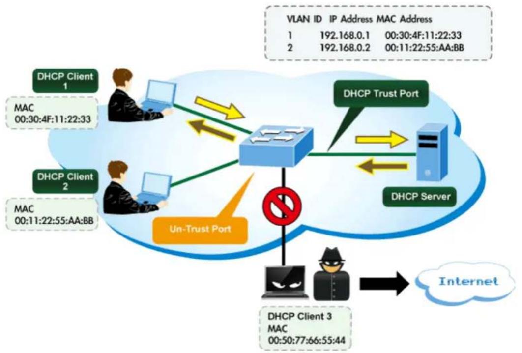
flowchart
graph TD
    subgraph_DHCP_Client_1["DHCP Client 1"]
        A["User"] --> B["Desktop"]
        C["User"] --> D["Desktop"]
        E["User"] --> F["Desktop"]
    end

    subgraph_DHCP_Client_2["DHCP Client 2"]
        G["User"] --> H["Desktop"]
        I["User"] --> J["Desktop"]
        K["User"] --> L["Desktop"]
    end

    subgraph_DHCP_Server["DHCP Server"]
        M["Client"] --> N["Internet"]
    end

    B <--> D
    D <--> F
    F <--> M
    style DHCP Client_1 fill:#4CAF50,stroke:#388E3C
    style DHCP Client_2 fill:#4CAF50,stroke:#388E3C
    style DHCP Server fill:#2196F3,stroke:#1976D2
    style DHCP Client_3 fill:#FFA500,stroke:#388E3C
    style DHCP Client_3 fill:#FFA500,stroke:#388E3C
    style DHCP Client_3 fill:#FFA500,stroke:#388E3C
    style DHCP Client_3 fill:#FFA500,stroke:#388E3C
    style DHCP Client_3 fill:#FFA500,stroke:#388E3C
    style DHCP Client_3 stroke:#000,stroke-width:2px
    note right of DHCP Client_1: UN-Trust Port
    note left of DHCP Client_2: MAC 00:30:4F:11:22:33
    note right of DHCP Client_3: MAC 00:50:77:66:55:44
    note right of DHCP Client_1: VLAN ID 1, IP Address 1, MAC Address 2
    note right of DHCP Client_2: VLAN ID 1, IP Address 2, MAC ID 2
    note right of DHCP Client_3: VLAN ID 1, IP Address 3, MAC ID 3
    note right of DHCP Client_4: VLAN ID 1, IP Address 4, MAC ID 4
    note right of DHCP Client_5: VLAN ID 2, IP Address 5, MAC ID 5
    note right of DHCP Client_6: VLAN ID 2, IP Address 6, MAC ID 6
    note right of DHCP Client_7: VLAN ID 3, IP Address 7, MAC ID 7
    note right of DHCP Client_8: VLAN ID 3, IP Address 8, MAC ID 8
    note right of DHCP Client_9: VLAN ID 4, IP Address 9, MAC ID 9
    note right of DHCP Client_10: VLAN ID 5, IP Address 10, MAC ID 10
    note right of DHCP Client_11: VLAN ID 6, IP Address 11, MAC ID 11
    note right of DHCP Client_12: VLAN ID 7, IP Address 12, MAC ID 12
    note right of DHCP Client_13: VLAN ID 8, IP Address 13, MAC ID 13
    note right of DHCP Client_14: VLAN ID 9, IP Address 14, MAC ID 14
    note right of DHCP Client_15: VLAN ID 10, IP Address 10, MAC ID 10
    note right of DHCP Client_16: VLAN ID 11, IP Address 11, MAC ID 11
    note right of DHCP Client_17: VLAN ID 12, IP Address 12, MAC ID 12
    note right of DHCP Client_18: VLAN ID 13, IP Address 13, MAC ID 13
    note right of DHCP Client_19: VLAN ID 14, IP Address 14, MAC ID 14
    note right of DHCP Client_20: VLAN ID 15, IP Address 15, MAC ID 15
    note right of DHCP Client_21: VLAN ID 16, IP Address 16, MAC ID 16
    note right of DHCP Client_22: VLAN ID 17, IP Address 17, MAC ID 17
    note right of DHCP Client_23: VLAN ID 18, IP Address 18, MAC ID 18
    note right of DHCP Client_24: VLAN ID 19, IP Address 19, MAC ID 19
    note right of DHCP Client_25: VLAN ID 20, IP Address 20, MAC ID 20
    note right of DHCP Client_26: VLAN ID 21, IP Address 21, MAC ID 21
    note right of DHCP Client_27: VLAN ID 22, IP Address 22, MAC ID 22
    note right of DHCP Client_28: VLAN ID 23, IP Address 23, MAC ID 23
    note right of DHCP Client_29: VLAN ID 24, IP Address 24, MAC ID 24
    note right of DHCP Client_30: VLAN ID 25, IP Address 35, MAC ID 35
4.5.6.1 DHCP Snooping Configuration
Configure DHCP Snooping on this page. in Figure 4-5-6-1 appears.
DHCP Snooping Configuration

Port Mode Configuration
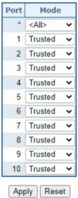
Figure 4-5-6-1: DHCP Snooping Configuration Screen Page Screenshot
The page includes the following fields:
| Object Description | |
| • Snooping Mode | Indicates the DHCP snooping mode operation. Possible modes are:■ Enabled: Enable DHCP snooping mode operation. When enable DHCP snooping mode operation, the request DHCP messages will be forwarded to trusted ports and only allowed reply packets from trusted ports.■ Disabled: Disable DHCP snooping mode operation. |
| • Port ModeConfiguration | Indicates the DHCP snooping port mode. Possible port modes are:■ Trusted: Configures the port as trusted sources of the DHCP message.■ Untrusted: Configures the port as untrusted sources of the DHCP message. |
Buttons

: Click to apply changes
: Click to undo any changes made locally and revert to previously saved values.
4.5.6.2 Snooping Table
This page displays the dynamic IP assigned information after DHCP Snooping mode is disabled. All DHCP clients obtained the dynamic IP address from the DHCP server will be listed in this table except for local VLAN interface IP addresses. Entries in the Dynamic DHCP snooping Table are shown on this page. The Dynamic DHCP Snooping Table screen in Figure 4-5-6-2 appears.
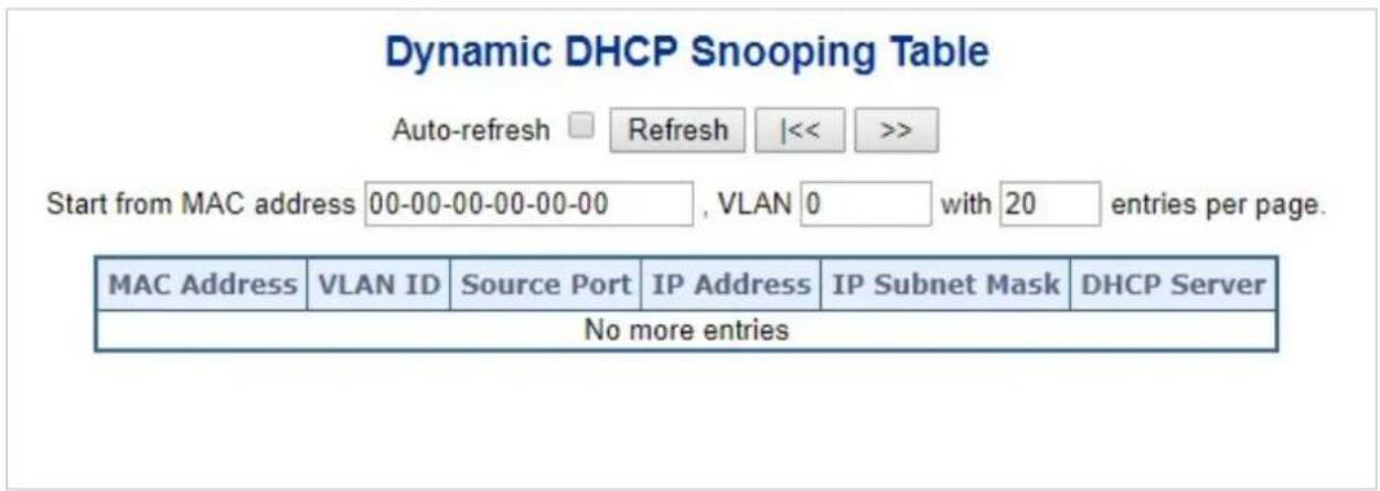
Figure 4-5-6-2: Dynamic DHCP Snooping Table Screen Page Screenshot
| Object Description | |
| • MAC Address | User MAC address of the entry. |
| • VLAN ID | VLAN-ID in which the DHCP traffic is permitted. |
| • Source Port | Switch Port Number for which the entries are displayed. |
| • IP Address | User IP address of the entry. |
| • IP Subnet Mask | User IP subnet mask of the entry. |
| • DHCP Server Address | DHCP Server address of the entry. |
Buttons
Auto-refresh ☐: Check this box to refresh the page automatically. Automatic refresh occurs every 3 seconds.
Refresh: Refreshes the displayed table starting from the input fields
Clear : Flushes all dynamic entries.
: It will use the last entry of the currently displayed table as a basis for the next lookup. When the end is reached the text "No more entries" is shown in the displayed table
|<<: To start over
4.5.7 IP Source Guard
4.5.7.1 IP Source Guard Configuration
IP Source Guard is a secure feature used to restrict IP traffic on DHCP snooping untrusted ports by filtering traffic based on the DHCP Snooping Table or manually configured IP Source Bindings. It helps prevent IP spoofing attacks when a host tries to spoof and use the IP address of another host. This page provides IP Source Guard related configuration. The IP Source Guard Configuration screen in Figure 4-5-7-1 appears.
IP Source Guard Configuration
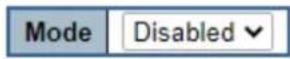
Translate Dynamic to Static
Port Mode Configuration
| Port | Mode | Max Dynamic Clients |
| * | ||
| 1 | Disabled | Unlimited |
| 2 | Disabled | Unlimited |
| 3 | Disabled | Unlimited |
| 4 | Disabled | Unlimited |
| 5 | Disabled | Unlimited |
| 6 | Disabled | Unlimited |
| 7 | Disabled | Unlimited |
| 8 | Disabled | Unlimited |
| 9 | Disabled | Unlimited |
| 10 | Disabled | Unlimited |
Apply Reset
Figure 4-5-7-1: IP Source Guard Configuration Screen Page Screenshot
The page includes the following fields:
| Object Description | |
| • Mode of IP Source Guard Configuration | Enable the Global IP Source Guard or disable the Global IP Source Guard. All configured ACEs will be lost when the mode is enabled. |
| • Port Mode Configuration | Specify IP Source Guard is enabled on which ports. Only when both Global Mode and Port Mode on a given port are enabled, IP Source Guard is enabled on this given port. |
| • Max Dynamic Clients | Specify the maximum number of dynamic clients can be learned on given ports. This value can be 0, 1, 2 and unlimited. If the port mode is enabled and the value of max dynamic client is equal 0, it means only allow the IP packets forwarding that are matched in static entries on the specific port. |
Buttons
Translate Dynamic to Static : Click to translate all dynamic entries to static entries.
Apply : Click to apply changes Reset : Click to undo any changes made locally and revert to previously saved values.
4.5.7.2 Static IP Source Guard Table
This page provides Static IP Source Guard Table. The Static IP Source Guard Table screen in Figure 4-5-7-2 appears.
Static IP Source Guard Table
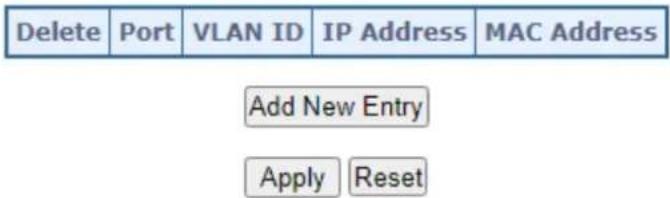
flowchart
graph TD
    A["Delete"] --> B["Port"]
    B --> C["VLAN ID"]
    C --> D["IP Address"]
    D --> E["MAC Address"]
    F["Add New Entry"] --> G["Apply Reset"]
Figure 4-5-7-2: Static IP Source Guard Table Screen Page Screenshot
The page includes the following fields:
| Object Description | |
| Delete | Check to delete the entry. It will be deleted during the next save. |
| Port | The logical port for the settings. |
| VLAN ID | The VLAN ID for the settings. |
| IP Address | Allowed Source IP address. |
| MAC Address | Allowed Source MAC address. |
Buttons
Add New Entry: Click to add a new entry to the Static IP Source Guard table.
Apply : Click to apply changes Reset : Click to undo any changes made locally and revert to previously saved values.
4.5.7.3 Dynamic IP Source Guard Table
This page provides Static IP Source Guard Table. The Static IP Source Guard Table screen in Figure 4-5-7-3 appears.
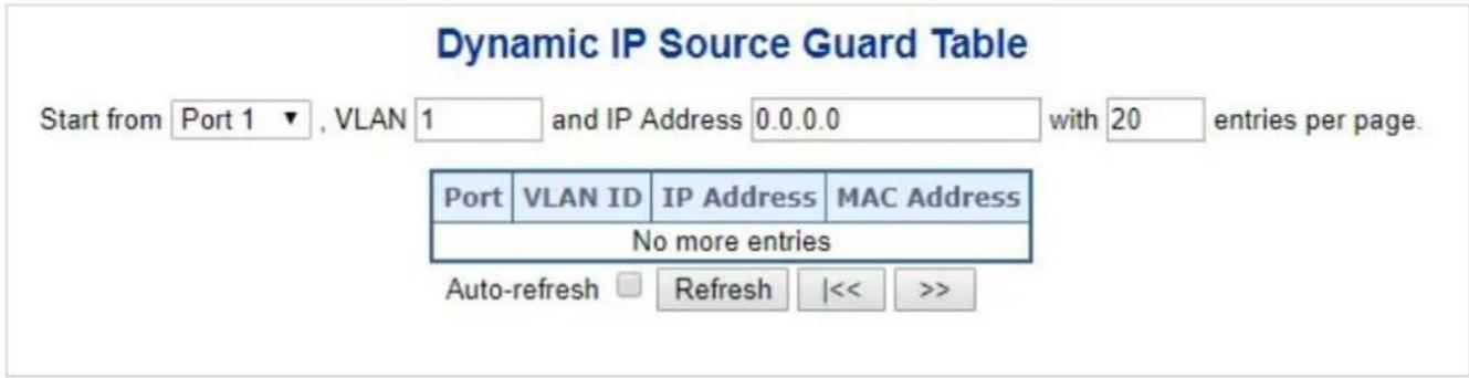
Figure 4-5-7-3: Static IP Source Guard Table Screen Page Screenshot
The page includes the following fields:
| Object Description | |
| • Port | Switch Port Number for which the entries are displayed. |
| • VLAN ID | VLAN-ID in which the IP traffic is permitted. |
| • IP Address | User IP address of the entry. |
| • MAC Address | Source MAC address. |
Buttons
Auto-refresh : Check this box to refresh the page automatically. Automatic refresh occurs every 3 seconds
Refresh
Refreshes the displayed table starting from the input fields..
Clear
Flushes all dynamic entries.
: Updates the table starting from the first entry in the Dynamic IP Source Guard Table.
|<<
Updates the table, starting with the entry after the last entry currently displayed.
4.5.8 ARP Inspection
4.5.8.1 ARP Inspection
ARP Inspection is a secure feature. Several types of attacks can be launched against a host or devices connected to Layer 2 networks by "poisoning" the ARP caches. This feature is used to block such attacks. Only valid ARP requests and responses can go through DUT. This page provides ARP Inspection related configuration. The ARP Inspection Configuration screen in Figure 4-5-8-1 appears.
ARP Inspection Configuration
Translate Dynamic to Static
Port Mode Configuration
| Port | Mode | Check VLAN | Log Type |
| * | |||
| 1 | Disabled | Disabled | None |
| 2 | Disabled | Disabled | None |
| 3 | Disabled | Disabled | None |
| 4 | Disabled | Disabled | None |
| 5 | Disabled | Disabled | None |
| 6 | Disabled | Disabled | None |
| 7 | Disabled | Disabled | None |
| 8 | Disabled | Disabled | None |
| 9 | Disabled | Disabled | None |
| 10 | Disabled | Disabled | None |
Save Reset
Figure 4-5-8-1: ARP Inspection Configuration Screen Page Screenshot
The page includes the following fields:
| Object Description | |
| • Mode of ARP Inspection Configuration | Enable the Global ARP Inspection or disable the Global ARP Inspection. |
| • Port Mode Configuration | Specify ARP Inspection is enabled on which ports. Only when both Global Mode and Port Mode on a given port are enabled, ARP Inspection is enabled on this given port. Possible modes are: |
■ Enabled: Enable ARP Inspection operation.
■ Disabled: Disable ARP Inspection operation.
If you want to inspect the VLAN configuration, you have to enable the setting of "Check VLAN". The default setting of "Check VLAN" is disabled. When the setting of "Check VLAN" is disabled, the log type of ARP Inspection will refer to the port setting. And the setting of "Check VLAN" is enabled, the log type of ARP Inspection will refer to the VLAN setting. Possible setting of "Check VLAN" are:
■ Enabled: Enable check VLAN operation.
■ Disabled: Disable check VLAN operation.
Only the Global Mode and Port Mode on a given port are enabled, and the setting of "Check VLAN" is disabled, the log type of ARP Inspection will refer to the port setting. There are four log types and possible types are:
■ None: Log nothing.
■ Deny: Log denied entries.
■ Permit: Log permitted entries.
■ ALL: Log all entries.
Buttons
Translate Dynamic to Static
Click to translate all dynamic entries to static entries.
Apply
: Click to apply changes
Reset
: Click to undo any changes made locally and revert to previously saved values.
4.5.8.2 ARP Inspection Static Table
This page provides Static ARP Inspection Table. The Static ARP Inspection Table screen in Figure 4-5-8-2 appears.
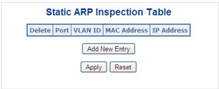
Figure 4-5-8-2: Static ARP Inspection Table Screen Page Screenshot
The page includes the following fields:
| Object Description | |
| Delete | Check to delete the entry. It will be deleted during the next save. |
| Port | The logical port for the settings. |
| VLAN ID | The VLAN ID for the settings. |
| MAC Address | Allowed Source MAC address in ARP request packets. |
| IP Address | Allowed Source IP address in ARP request packets. |
Buttons
Add New Entry
Click to add a new entry to the Static ARP Inspection table.
Apply
: Click to apply changes
Reset
: Click to undo any changes made locally and revert to previously saved values.
4.5.8.3 Dynamic ARP Inspection Table
Entries in the Dynamic ARP Inspection Table are shown on this page. The Dynamic ARP Inspection Table contains up to 1024 entries, and is sorted first by port, then by VLAN ID, then by MAC address, and then by IP address. The Dynamic ARP Inspection Table screen in Figure 5-8-3 appears.

Figure 5-8-3: Dynamic ARP Inspection Table Screenshot
Navigating the ARP Inspection Table
Each page shows up to 99 entries from the Dynamic ARP Inspection table, default being 20, selected through the "entries per Page" input field. When first visited, the web page will show the first 20 entries from the beginning of the Dynamic ARP Inspection Table.
The "Start from port address", "VLAN", "MAC address" and "IP address" input fields allow the user to select the starting point in the Dynamic ARP Inspection Table. Clicking the "Refresh" button will update the displayed table starting from that or the closest next Dynamic ARP Inspection Table match. In addition, the two input fields will - upon a "Refresh" button click - assume the value of the first displayed entry, allowing for continuous refresh with the same start address.
The “>>” will use the last entry of the currently displayed as a basis for the next lookup. When the end is reached the text "No more entries" is shown in the displayed table. Use the "|<<" button to start over. The page includes the following fields:
| Object Description | |
| • Port | The port number for which the status applies. Click the port number to see the status for this particular port. |
| • VLAN ID | The VLAN ID of the entry. |
| • MAC Address | The MAC address of the entry. |
| • IP Address | The IP address of the entry. |
Buttons
Auto-refresh ☐: Check this box to refresh the page automatically. Automatic refresh occurs every 3 seconds.
Refresh
Refreshes the displayed table starting from the "Start from MAC address" and "VLAN" input fields.
Clear
: Flushes all dynamic entries.
k<
Updates the table starting from the first entry in the MAC Table, i.e. the entry with the lowest VLAN ID and MAC address.
Updates the table, starting with the entry after the last entry currently displayed.
4.6 Ring
4.6.1 ERPS Ring
ITU-T G.8032 Ethernet Ring protection switching (ERPS) is a link layer protocol applied on Ethernet loop protection to provide sub-50ms protection and recovery switching for Ethernet traffic in a ring topology.
ERPS provides a faster redundant recovery than Spanning Tree topology. The action is similar to STP or RSTP, but the algorithms between them are not the same. In the Ring topology, every switch should be enabled with Ring function and two ports should be assigned as the member ports in the ERPS. Only one switch in the Ring group would be set as the RPL owner switch that one port would be blocked, called owner port, and PRL neighbor switch has one port that one port would be blocked, called neighbor port that connect to owner port directly and this link is called the Ring Protection Link or RPL. Each switch will sends ETH-CCM message to check the link status in the ring group. When the failure of network connection occurs, the nodes block the failed link and report the signal failure message, the RPL owner switch will automatically unblocks the PRL to recover from the failure.
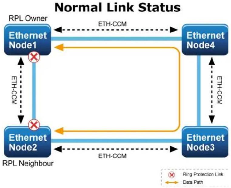
flowchart
graph TD
    A["Ethernet Node1"] -->|RPL Owner| B["Ethernet Node4"]
    B -->|ETH-CCM| A
    C["Ethernet Node2"] -->|RPL Neighbour| D["Ethernet Node3"]
    D -->|ETH-CCM| B
    E["×"] --> A
    F["×"] --> C
    G["×"] --> D
    style A fill:#0066cc,stroke:#000
    style B fill:#0066cc,stroke:#000
    style C fill:#0066cc,stroke:#000
    style D fill:#0066cc,stroke:#000
    style E fill:#fff,stroke:#000
    style F fill:#fff,stroke:#000
    style G fill:#fff,stroke:#000
    note right of A "Ring Protection Link"
    note right of G "Data Path"
Fault Link Status
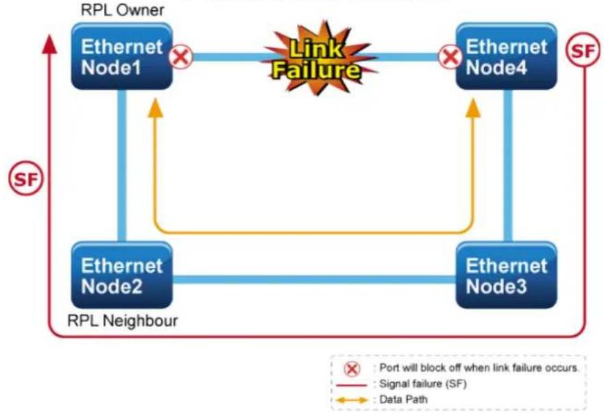
flowchart
graph TD
    A["RPL Owner"] -->|SF| B["Ethernet Node1"]
    A -->|SF| C["Ethernet Node2"]
    A -->|SF| D["Ethernet Node3"]
    A -->|SF| E["Ethernet Node4"]
    B -->|SF| F["RPL Neighbour"]
    C -->|SF| F
    D -->|SF| F
    E -->|SF| F
    F -->|SF| G["Link Failure"]
    G -->|SF| H["Port will block off when link failure occurs."]
    G -->|SF| I["Signal failure (SF)"]
    G -->|SF| J["Data Path"]
4.6.1.1 MEP Configuration
The Maintenance Entity Point instances are configured here; screen in Figure 4-6-1-1 appears.
Maintenance Entity Point
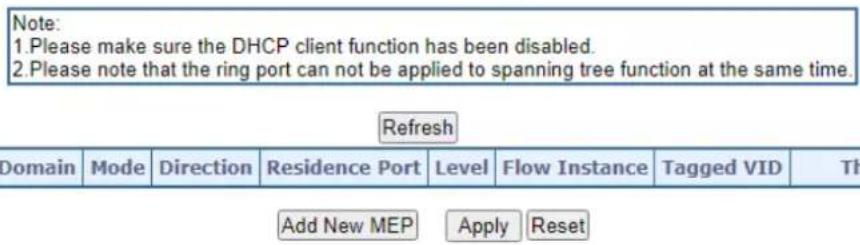
Figure 4-6-1-1: MEP configuration page screenshot
The page includes the following fields:
| Object | Description |
| Delete | This box is used to mark a MEP for deletion in next Save operation. |
| Instance | The ID of the MEP. Click on the ID of a MEP to enter the configuration page. |
| Domain | Port: This is a MEP in the Port Domain. 'Flow Instance' is a Port.Esp: Future useEvc: This is a MEP in the EVC Domain. 'Flow Instance' is a EVCMpls: Future use |
| Mode | MEP: This is a Maintenance Entity End Point.MIP: This is a Maintenance Entity Intermediate Point. |
| Direction | Ingress: This is a Ingress (down) MEP - monitoring ingress traffic on 'Residence Port'.Egress: This is a Egress (up) MEP - monitoring egress traffic on 'Residence Port'. |
| • Residence Port | The port where MEP is monitoring - see 'Direction'. |
| • Level | The MEG level of this MEP. |
| • Flow Instance | The MEP is related to this flow - See 'Domain'. |
| • Tagged VID | Port MEP: An outer C/S-tag (depending on VLAN Port Type) is added with this VID.Entering '0' means no TAG added. |
| • This MAC | The MAC of this MEP - can be used by other MEP when unicast is selected (Info only). |
| • Alarm | There is an active alarm on the MEP. |
Buttons
Refresh
Click to refresh the page immediately.
Add New MEP
Click to add a new MEP entry
Apply
: Click to save changes.
Reset
: Click to undo any changes made locally and revert to previously saved values.
4.6.1.2 Detailed MEP Configuration
This page allows the user to inspect and configure the current MEP Instantly as the screen in Figure 4-6-1-2 appears.
MEP Configuration
Refroch
Instance Data
| Instance | Domain | Mode | Direction | Residence Port | Flow Instance | Tagged VID | EPS Instance | This MAC |
| 1 | Port | Mep | Down | 1 | 1 | 0 | 0 | 00-01-C1-00-00-01 |
Instance Configuration
| Level | Format | Domain Name | MEG ID | MEP ID | Tagged VID | cLevel | cMEG | cMEP | cAIS | cLCK | cSSF | aBLK | aTSF | |
| 0 | ITU ICC | ICC000MEG0000 | 1 | 0 |
Peer MEP Configuration
| Delete | Peer MEP ID | Unicast Peer MAC | cLOC | cRDI | cPeriod | cPriority | |
| No Peer MEP Added | |||||||
Add New Peer MEP
Functional Configuration
| Continuity Check | APS Protocol | ||||||||
| Enable | Priority | Frame rate | TLV | Enable | Priority | Cast | Type | Last Octet | |
| √ | 0 | 1 f/sec ▼ | □ | √ | 0 | Multi ▼ | R-APS ▼ | 1 | |
Fault Management
Performance Monitoring
TLV Configuration
| Organization Specific TLV (Global) | ||||
| OUI First | OUI Second | OUI Third | Sub-Type | Value |
| 0 | 0 | 12 | 1 | 2 |
TLV Status
| Peer MEP ID | CC Organization Specific | CC Port Status | CC Interface Status | |||||||||
| OUI First | OUI Second | OUI Third | Sub-Type | Value | Last RX | Value | Last RX | Value | Last RX | |||
| 4 | 0 | 0 | 0 | 0 | 0 | 0 | 0 | |||||
Link State Tracking

Apply Reset
Figure 4-6-1-2: Detail MEP configuration page screenshot
The page includes the following fields:
Instant Data:
| Object Description | |
| • Instance | The ID of the MEP. |
| • Domain | See help on MEP to create Web |
| • Mode | See help on MEP to create Web |
| • Direction | See help on MEP to create Web |
| • Residence Port | See help on MEP to create Web |
| • Flow Instance | See help on MEP to create Web |
| • Tagged VID | See help on MEP to create Web |
| • This MAC | See help on MEP to create Web |
Instant Configuration:
| Object Description | |
| • Level | See help on MEP to create Web |
| • Format | This is the configuration of the two possible Maintenance Association Identifier formats.■ITU ICC: This is defined by ITU. 'ICC' can be max. 6 char. 'MEG id' can be max. 7 char.■IEEE String: This is defined by IEEE. 'Domain Name' can be max. 8 char. 'MEG id' can be max. 8 char. |
| • Domain Name | This is either ITU ICC (MEG ID value[1-6]) or IEEE Maintenance Domain Name - depending on 'Format'. See 'Format'. |
| • MEG Id | This is either ITU UMC (MEG ID value[7-13]) or IEEE Short MA Name - depending on 'Format'. See 'Format'. In case of ITU ICC format this can be max. 7 char. If only 6 char. is entered the MEG ID value[13] will become NULL. |
| • MEP Id | This value will become the transmitted two byte CCM MEP ID. |
| • Tagged VID | This value will be the VID of a TAG added to the OAM PDU. |
| • cLevel | Fault Cause indicating that a CCM is received with a lower level than the configured for this MEP. |
| • cMEG | Fault Cause indicating that a CCM is received with a MEG ID different from configured for this MEP. |
| • cMEP | Fault Cause indicating that a CCM is received with a MEP ID different from all 'Peer MEP ID' configured for this MEP. |
| • cAIS | Fault Cause indicating that AIS PDU is received. |
| • cLCK | Fault Cause indicating that LCK PDU is received. |
| • cSSF | Fault Cause indicating that server layer is indicating Signal Fail. |
| • aBLK | The consequent action of blocking service frames in this flow is active. |
| • aTSF | The consequent action of indicating Trail Signal Fail to-wards protection is active. |
Peep MEP Configuration:
| Object Description | |
| Delete | This box is used to mark a Peer MEP for deletion in next Save operation. |
| Peer MEP ID | This value will become an expected MEP ID in a received CCM - see 'cMEP'. |
| Unicast Peer MAC | This MAC will be used when unicast is selected with this peer MEP. Also this MAC is used to create HW checking of receiving CCM PDU (LOC detection) from this MEP. |
| cLOC | Fault Cause indicating that no CCM has been received (in 3,5 periods) - from this peer MEP. |
| cRDI | Fault Cause indicating that a CCM is received with Remote Defect Indication - from this peer MEP. |
| cPeriod | Fault Cause indicating that a CCM is received with a period different what is configured for this MEP - from this peer MEP. |
| cPriority | Fault Cause indicating that a CCM is received with a priority different what is configured for this MEP - from this peer MEP. |
Buttons
Add New Peer MEP
Click to add a new peer MEP.
Functional Configuration
Continuity Check:
Functional Configuration
| Continuity Check | APS Protocol | ||||||||
| Enable | Priority | Frame rate | TLV | Enable | Priority | Cast | Type | Last Octet | |
| √ | 0 | 1 f/sec ▼ | □ | √ | 0 | Multi ▼ | R-APS ▼ | 1 | |
Fault Management
Performance Monitoring
| Object Description | |
| • Enable | Continuity Check based on transmitting/receiving CCM PDU can be enabled/disabled. The CCM PDU is always transmitted as Multi-cast Class 1. |
| • Priority | The priority to be inserted as PCP bits in TAG (if any). In case of enable of Continuity Check and Loss Measurement both implemented on SW based CCM, 'Priority' has to be the same. |
| • Frame rate | Selecting the frame rate of CCM PDU. This is the inverse of transmission period as described in Y.1731. This value has the following uses:* The transmission rate of the CCM PDU.* Fault Cause cLOC is declared if no CCM PDU has been received within 3.5 periods - see 'cLOC'.* Fault Cause cPeriod is declared if a CCM PDU has been received with different period - see 'cPeriod'.Selecting 300f/sec or 100f/sec will configure HW based CCM (if possible).Selecting other frame rates will configure SW based CCM. In case of enable of Continuity Check and Loss Measurement both implemented on SW based CCM, 'Frame Rate' has to be the same. |
APS Protocol:
| Object Description | |
| • Enable | Automatic Protection Switching protocol information transportation based on transmitting/receiving R-APS/L-APS PDU can be enabled/disabled. Must be enabled to support ERPS/ELPS implementing APS. This is only valid with one Peer MEP configured. |
| • Priority | The priority to be inserted as PCP bits in TAG (if any). |
| • Cast | Selection of APS PDU transmitted unicast or multi-cast. The unicast MAC will be taken from the 'Unicast Peer MAC' configuration. Unicast is only valid for L-APS - see 'Type'. The R-APS PDU is always transmitted with multi-cast MAC described in G.8032. |
| • Type | R-APS: APS PDU is transmitted as R-APS - this is for ERPS.L-APS: APS PDU is transmitted as L-APS - this is for ELPS. |
| • Last Octet | This is the last octet of the transmitted and expected RAPS multi-cast MAC. In G.8031 (03/2010) a RAPS multi-cast MAC is defined as 01-19-A7-00-00-XX. In current standard the value for this last octet is '01' and the usage of other values is for further study. |
Buttons
Fault Management
Click to go to Fault Management page.
Performance Monitoring
Click to go to Performance Monitor page.
TLV Configuration:
Configuration of the OAM PDU TLV. Currently only TLV in the CCM is supported.
TLV Configuration
| Organization Specific TLV (Global) | ||||
| OUI First | OUI Second | OUI Third | Sub-Type | Value |
| 0 | 0 | 12 | 1 | 2 |
TLV Status
| Peer MEP ID | CC Organization Specific | CC Port Status | CC Interface Status | |||||||||
| OUI First | OUI Second | OUI Third | Sub-Type | Value | Last RX | Value | Last RX | Value | Last RX | |||
| 4 | 0 | 0 | 0 | 0 | 0 | 0 | 0 | |||||
Link State Tracking
| Enable |
| Apply | Reset |
Organization Specific TLV(Global)
| Object Description | |
| • OUI First | The transmitted first value in the OS TLV OUI field. |
| • OUI Second | The transmitted second value in the OS TLV OUI field. |
| • OUI Third | The transmitted third value in the OS TLV OUI field. |
| • Sub-Type | he transmitted value in the OS TLV Sub-Type field. |
| • Value | The transmitted value in the OS TLV Value field. |
TLV Status:
Display of the last received TLV. Currently only TLV in the CCM is supported.
| Object Description | |
| • OUI First | The last received first value in the OUI field. |
| • OUI Second | The last received second value in the OS TLV OUI field. |
| • OUI Third | The last received third value in the OS TLV OUI field. |
| • Sub-Type | The last received value in the OS TLV Sub-Type field. |
| • Value | The last received value in the OS TLV Value field. |
| • Last RX | OS TLV was received in the last received CCM PDU. |
| • CC Port Status - Value | The last received value in the PS TLV Value field. |
| CC Port Status - Last RX | PS TLV was received in the last received CCM PDU. |
| CC Interface Status - Value | The last received value in the IS TLV Value field. |
| CC Interface Status - Last RX | IS TLV was received in the last received CCM PDU. |
| Link State Tracking Enable | When LST is enabled in an instance, Local SF or received 'isDown' in CCM Interface Status TLV, will bring down the residence port.Only valid in Up-MEP. The CCM rate must be 1 f/s or faster. |
Buttons
Refresh
Click to refresh the page immediately.
Save
Click to save changes.
Reset
: Click to undo any changes made locally and revert to previously saved values.
4.6.1.3 Ethernet Ring Protocol Switch
The Ethernet Ring Protection Switch instances are configured here; screen in Figure 4-6-1-3 appears.
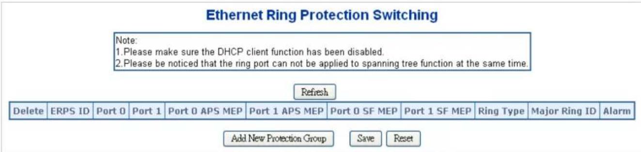
Figure 4-6-1-3: Ethernet Ring Protocol Switch page screenshot
The page includes the following fields:
| Object Description | |
| Delete | This box is used to mark an ERPS for deletion in next Save operation. |
| Port 0 | This will create a Port 0 of the switch in the ring. |
| Port 1 | This will create "Port 1" of the switch in the Ring. As interconnected sub-ring will have only one ring port, "Port 1" is configured as "0" for interconnected sub-ring. "0" in this field indicates that no "Port 1" is associated with this instance |
| Port 0 SF MEP | The Port 0 Signal Fail reporting MEP. |
| Port 1 SF MEP | The Port 1 Signal Fail reporting MEP. As only one SF MEP is associated with interconnected sub-ring without virtual channel, it is configured as "0" for such ring instances. "0" in this field indicates that no Port 1 SF MEP is associated withthis instance. |
| • Port 0 APS MEP | The Port 0 APS PDU handling MEP. |
| • Port 1 APS MEP | The Port 1 APS PDU handling MEP. As only one APS MEP is associated with interconnected sub-ring without virtual channel, it is configured as "0" for such ring instances. "0" in this field indicates that no Port 1 APS MEP is associated with this instance. |
| • Ring Type | Type of Protecting ring. It can be either major ring or sub-ring.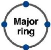 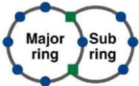 Single-ring Network Major-ring + Sub-ring Network Single-ring Network Major-ring + Sub-ring Network |
| • Major Ring ID | Major ring group ID for the interconnected sub-ring. It is used to send topology change updates on major ring. If ring is major, this value is same as the protection group ID of this ring. |
| • Alarm | There is an active alarm on the ERPS. |
Buttons
Refresh
Click to refresh the page immediately.
Add New Protection Group
Click to add a new Protection group entry.
Save
Click to save changes.
Reset
Click to undo any changes made locally and revert to previously saved values.
4.6.1.4 Ethernet Ring Protocol Switch Configuration
This page allows the user to inspect and configure the current ERPS instantly as the screen in Figure 4-6-1-4 appears.
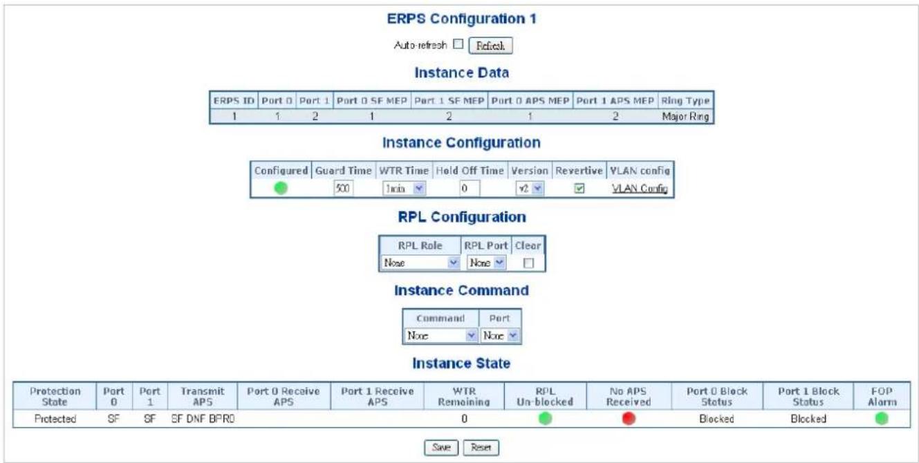
Figure 4-6-1-4: Ethernet Ring Protocol Switch Configuration page screenshot
The page includes the following fields:
Instant Data:
| Object Description | |
| • ERPS ID | The ID of the Protection group. |
| • Port 0 | See help on ERPS to create Web |
| • Port 1 | See help on ERPS to create Web |
| • Port 0 SF MEP | See help on ERPS to create Web |
| • Port 1 SF MEP | See help on ERPS to create Web |
| • Port 0 APS MEP | See help on ERPS to create Web |
| • Port 1 APS MEP | See help on ERPS to create Web |
| • Ring Type | Type of Protecting ring -- can be either major ring or sub-ring. |
Instant Configuration:
| Object Description | |
| Configuration | Red: This ERPS is only created and has not yet been configured - is not active.Green: This ERPS is configured - is active. |
| Guard Time | Guard timeout value to be used to prevent ring nodes from receiving outdated R-APS messages.The period of the guard timer can be configured in 10 ms steps between 10 ms and 2 seconds, with a default value of 500 ms |
| WTR Time | The Wait To Restore timing value to be used in revertive switching.The period of the WTR time can be configured by the operator in 1 minute steps between 5 and 12 minutes with a default value of 5 minutes. |
| Hold Off Time | The timing value to be used to make persistent check on Signal Fail before switching.The range of the hold off timer is 0 to 10 seconds in steps of 100 ms |
| Version | ERPS Protocol Version - v1 or v2 |
| Revertive | In Revertive mode, after the conditions causing a protection switch has cleared, the traffic channel is restored to the working transport entity, i.e., blocked on the RPL.In Non-Revertive mode, the traffic channel continues to use the RPL, if it is not failed, after a protection switch condition has cleared. |
| VLAN Config | VLAN configuration of the Protection Group. Click on the "VLAN Config" link to configure VLANs for this protection group. |
PRL Configuration:
| Object Description | |
| • PRL Role | It can be either RPL owner or RPL Neighbor. |
| • PRL Port | This allows to select the east port or west port as the RPL block. |
| • Clear | If the owner has to be changed, then the clear check box allows to clear the RPL owner for that ERPS ring. |
Instant Command:
| Object Description | |
| • Command | Administrative command. A port can be administratively configured to be in either manual switch or forced switch state. |
| • Port | Port selection - Port0 or Port1 of the protection Group on which the command is applied. |
Instant State:
Instance State
| Protection State | Port 0 | Port 1 | Transmit APS | Port 0 Receive APS | Port 1 Receive APS | WTR Remaining | RPL Un-blocked | No APS Received | Port 0 Block Status | Port 1 Block Status | FOP Alarm |
| Protected | SF | SF | SF DNF BPRO | 0 | Blocked | Blocked |
Save Reset
| Object Description | |
| • Protection State | ERPS state according to State Transition Tables in G.8032. |
| • Port 0 | OK: State of East port is okSF: State of East port is Signal Fail |
| • Port 1 | OK: State of West port is okSF: State of West port is Signal Fail |
| • Transmit APS | The transmitted APS according to State Transition Tables in G.8032. |
| • Port 0 Receive APS | The received APS on Port 0 according to State Transition Tables in G.8032. |
| • Port 1 Receive APS | The received APS on Port 1 according to State Transition Tables in G.8032. |
| • WTR Remaining | Remaining WTR timeout in milliseconds. |
| • RPL Un-blocked | APS is received on the working flow. |
| • No APS Received | RAPS PDU is not received from the other end. |
| • Port 0 Block Status | Block status for Port 0 (Both traffic and R-APS block status). R-APS channel is never blocked on sub-rings without virtual channel. |
| • Port 1 Block Status | Block status for Port 1 (Both traffic and R-APS block status). R-APS channel is never blocked on sub-rings without virtual channel. |
| • FOP Alarm | Failure of Protocol Defect(FOP) status. If FOP is detected, red LED glows; else green LED glows. |
Buttons
Save
Click to save changes.
Auto-refresh ☐: Check this box to refresh the page automatically. Automatic refresh occurs every 6 seconds.
Refresh
Click to refresh the page immediately.
Reset
: Click to undo any changes made locally and revert to previously saved values.
4.6.1.5 Ethernet Ring Protocol Switch
This page allows the user to configure the ERPS by wizard; screen in Figure 4-6-1-5 appears.
Ring Wizard
Note:
- Please make sure the DHCP client function has been disabled.
- Please be noticed that the ring port can not be applied to spanning tree function at the same time.
ALL Switch Number (3 \~ 30):
Number ID: 1
Next
Configuration
Switch-3

Mep:6
Mep:1
(Owner)
Switch-1

Vlan

Mep:2
[Non-Text]
Mep:3
(Neighbour)
Switch-2

Set
Show Topology
Figure 4-6-1-5: Ring Wizard page screenshot
The page includes the following fields:
| Object Description | |
| • All Switch Numbers | Set all the switch numbers for the ring group. The default number is 3 and maximum number is 30. |
| • Number ID | The switch where you are requesting ERPS. |
| • Port | Configures the port number for the MEP. |
| • VLAN | Set the ERPS VLAN. |
Buttons
Next
Click to configure ERPS.
Set
Click to save changes.
Show Topology
Click to show the ring topology.
4.6.1.6 Ring Wizard Example
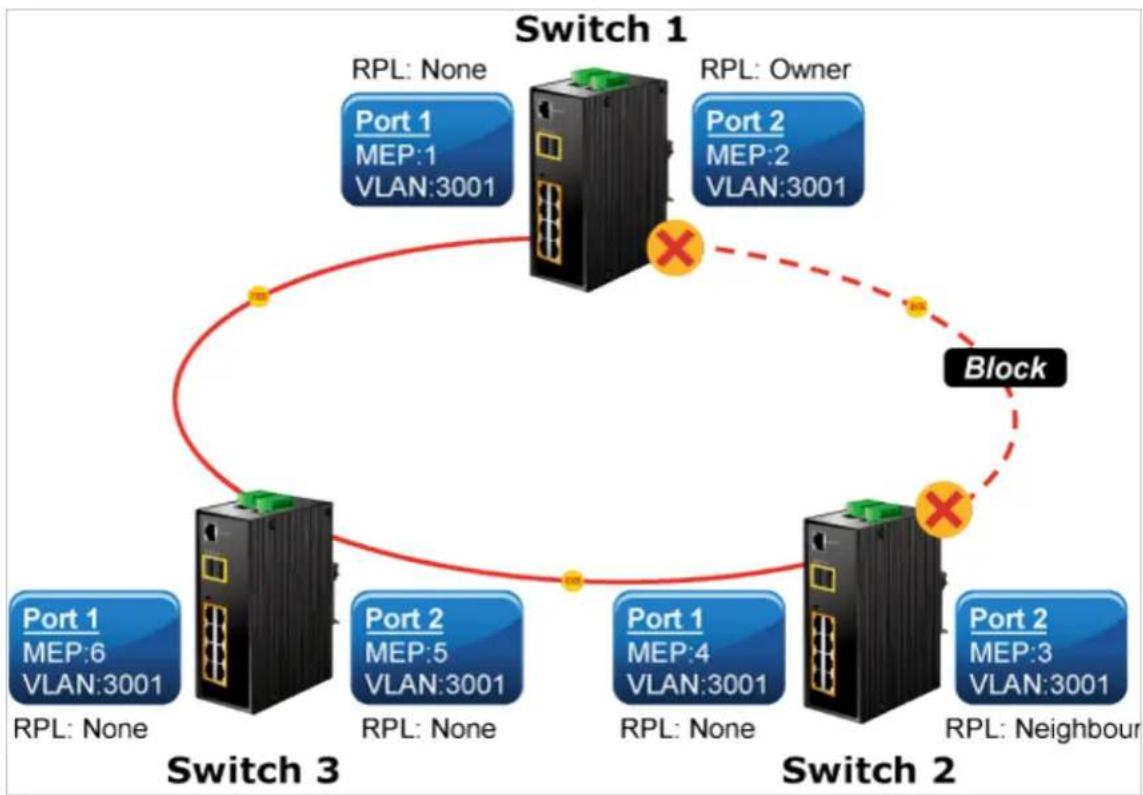
flowchart
graph TD
    A["Switch 1"] -->|RPL: None| B["Port 1\nMEP:1\nVLAN:3001"]
    A -->|RPL: Owner| C["Port 2\nMEP:2\nVLAN:3001"]
    D["Switch 2"] -->|RPL: None| E["Port 1\nMEP:4\nVLAN:3001"]
    D -->|RPL: Neighbour| F["Port 2\nMEP:3\nVLAN:3001"]
    G["Switch 3"] -->|RPL: None| H["Port 1\nMEP:6\nVLAN:3001"]
    G -->|RPL: Owner| I["Port 2\nMEP:5\nVLAN:3001"]
    J["Block"] -.-> A
    J -.-> D
Figure 4-6-1-6: Ring Example Diagram
The above topology often occurs on using ERPS protocol. The multi switch constitutes a single ERPS ring; all of the switches only are configured as an ERPS in VLAN 3001, thereby constituting a single MRPP ring.
| Switch ID | Port | MEP ID | RPL Type | VLAN Group |
| Switch 1 | Port 1 1 | None 3001 | ||
| Port 2 | 2 | Owner | 3001 | |
| Switch 2 | Port 1 4 | None 3001 | ||
| Port 2 | 3 | Neighbor | 3001 | |
| Switch 3 | Port 1 6 | None 3001 | ||
| Port 2 5 | None 3001 |
Table 4-6-1-1: ERPS Configuration Table
The scenario described as follows:
- Disable DHCP client and set proper static IP for Switches 1, 2 & 3. In this example, switch 1 is 192.168.0.101; switch 2 is 192.168.0.102 and switch 3 is 192.168.0.103.
- On Switches 1, 2 & 3, disable spanning tree protocol to avoid confliction with ERPS.
Setup steps
Set ERPS Configuration on Switch 1
Connect PC to switch 1 directly; don't connect to port 1 & 2
Logging on to the Switch 1 and click "Ring > Ring Wizard"
Set "All Switch Number" = 3 and "Number ID" = 1; click "Next" button to set the ERPS configuration for Switch 1.
ALL Switch Number (3 \~ 30): 3 Number ID: 1 Next
Set "MEP1" = Port1, "MEP2" = Port2 and VLAN ID = 3001; click "Set" button to save the ERPS configuration for Switch 1.
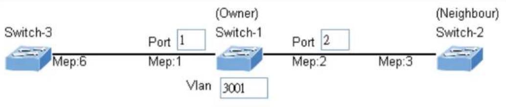
flowchart
graph LR
    A["Switch-3"] -->|Mep:6| B["(Owner)"]
    B -->|Port 1| C["Switch-1"]
    C -->|Vlan 3001| D["(Neighbour)"]
    C -->|Port 2| E["(Owner)"]
    E -->|Mep:2| F["(Neighbour)"]
    F -->|Mep:3| G["(Neighbour)"]
Set ERPS Configuration on Switch 2
Connect PC to switch 2 directly; don't connect to port 1 & 2
Logging on to the Switch 2 and click "Ring > Ring Wizard"
Set "All Switch Number" = 3 and "Number ID" = 2; click "Next" button to set the ERPS configuration for Switch 2.
ALL Switch Number (3 \~ 30): 3 Number ID: 2 Next
Set "MEP3" = Port2, "MEP4" = Port1 and VLAN ID = 3001; click "Set" button to save the ERPS configuration for Switch 2.
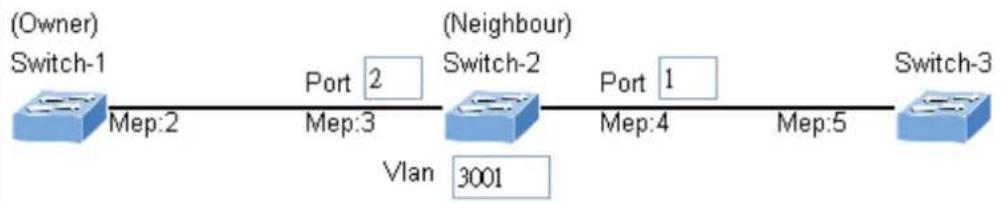
flowchart
graph LR
    A["(Owner) Switch-1"] -->|Mep:2| B["(Neighbour) Switch-2"]
    B -->|Port 1| C["Switch-3"]
    B -->|Mep:4| D["Vlan 3001"]
    B -->|Mep:3| E["Port 2"]
    E --> A
Set ERPS Configuration on Switch 3
Connect PC to switch 3 directly; don't connect to port 1 & 2
Logging on to the Switch 3 and click "Ring > Ring Wizard"
Set "All Switch Number" = 3 and "Number ID" = 3; click "Next" button to set the ERPS configuration for Switch 3.
ALL Switch Number (3 \~ 30): 3 Number ID: 3 Next
Set "MEP5" = Port2, "MEP6" = Port1 and VLAN ID = 3001; click "Set" button to save the ERPS configuration for Switch 3.
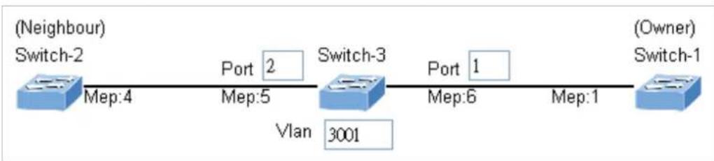
flowchart
graph LR
    A["(Neighbour) Switch-2"] -->|Mep:4| B["Switch-3"]
    B -->|Mep:5| C["Switch-3"]
    B -->|Port 2| D["Vlan 3001"]
    B -->|Port 1| E["Switch-1"]
    E -->|Mep:6| F["(Owner) Switch-1"]
    F -->|Mep:1| E

To avoid loop, please don't connect Switches 1, 2 & 3 together in the ring topology before configuring the end of ERPS.
Follow the configuration or ERPS wizard to connect Switches 1, 2 and 3 together to establish ERPS application:
MEP2 MEP3 = Switch1 / Port2 Switch2 / Port2
MEP4 MEP5 = Switch2 / Port1 Switch3 / Port2
MEP1 MEP6 = Switch1 / Port1 Switch3 / Port1.
4.7 Maintenance
4.7.1 Switch Maintenance
This chapter shows how to upgrade the firmware, how to save the switch running configure and how to download/upload the configure file, etc.
4.7.1.1 Web Firmware Upgrade
This page facilitates an update on the firmware controlling the switch. The Web Firmware Upgrade screen in Figure 4-7-1-1 appears.
Firmware Upload
Choose File
No file chosen
Upload
Figure 4-7-1-1: Web Firmware Upgrade Page Screenshot
To open Firmware Upgrade screen, perform the following:
- Click Maintenance -> Web Firmware Upgrade.
- The Firmware Upgrade screen is displayed as in Figure 4-7-1-1
- Click the “Choose File” button of the Main page; the system would pop up the file selection menu to choose firmware.
- Select on the firmware and then click "Upload". The Software Upload Progress would show the file with upload status.
- Once the software is loaded to the system successfully, the following screen appears. The system will load the new software after reboot.
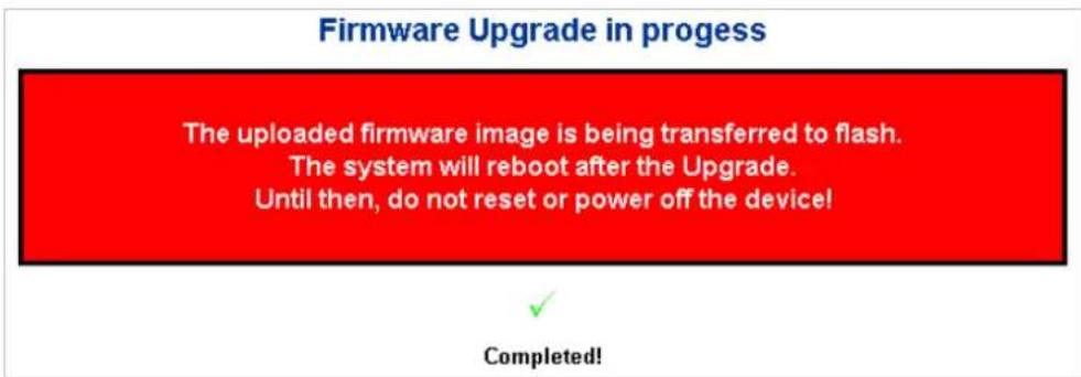
Figure 4-7-1-2: Software Successfully Loaded Notice Screen

DO NOT Power OFF the Managed Metro Switch until the update progress is complete.

Do not quit the Firmware Upgrade page without pressing the "OK" button after the image is loaded. Or the system won't apply the new firmware. User has to repeat the firmware upgrade processes.
4.7.1.2 Save Startup Config
This function allows to save the current configuration, thereby ensuring that the current active configuration can be used at the next reboot as the screen in Figure 4-7-1-3 appears. After saving the configuration, the screen in Figure 4-7-1-4 will appear.
Save Running Configuration to startup-config
Save Configuration
Figure 4-7-1-3: Configuration Save Page Screenshot
Save Running Configuration to startup-config
startup-config saved successfully.
Figure 4-7-1-4: Finish Saving Page Screenshot
4.7.1.3 Configuration Download
The switch stores its configuration in a number of text files in CLI format. The files are either virtual (RAM-based) or stored in flash on the switch.
There are three system files:
- running-config: A virtual file that represents the currently active configuration on the switch. This file is volatile.
- startup-config: The startup configuration for the switch, read at boot time.
- default-config: A read-only file with vendor-specific configuration. This file is read when the system is restored to default settings.
It is also possible to store up to two other files and apply them to running-config, thereby switching configuration.
Configuration Download page allows the download of the running-config, startup-config and default-config on the switch. Please refer to Figure 4-7-1-5 shown below.
Download Configuration
Select configuration file to save.
Please note: running-config may take a while to prepare for download.
File Name
○ running-config
○ default-config
○ startup-config
Download Configuration
Figure 4-7-1-5: Configuration Download Page Screenshot
4.7.1.4 Configuration Upload
Configuration Upload page allows the upload of the running-config and startup-config on the switch. Please refer to Figure 4-7-1-6 shown below.
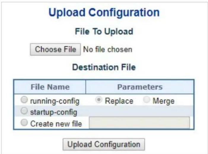
Figure 4-7-1-6: Configuration Upload Page Screenshot
If the destination is running-config, the file will be applied to the switch configuration. This can be done in two ways:
- Replace mode: The current configuration is fully replaced with the configuration in the uploaded file.
- Merge mode: The uploaded file is merged into running-config.
If the file system is full (i.e. contains the three system files mentioned above plus two other files), it is not possible to create new files, but an existing file must be overwritten or another deleted first.
4.7.1.5 Configuration Activate
Thje Configure Activate page allows to activate the startup-config and default-config files present on the switch. Please refer to Figure 4-7-1-7 shown below.
Activate Configuration
Select configuration file to activate. The previous configuration will be completely replaced, potentially leading to loss of management connectivity.
Please note: The activated configuration file will not be saved to startup-config automatically.

Activate Configuration
Figure 4-7-1-7: Configuration Activate Page Screenshot
It is possible to activate any of the configuration files present on the switch, except for running-config which represents the currently active configuration.
Select the file to activate and click Activate Configuration. This will initiate the process of completely replacing the existing configuration with that of the selected file.
4.7.1.6 Configuration Delete
The Configure Delete page allows to delete the startup-config and default-config files which are stored in FLASH. If this is done and the switch is rebooted without a prior Save operation, this effectively resets the switch to default configuration. Please refer to Figure 4-7-1-8 shown below.
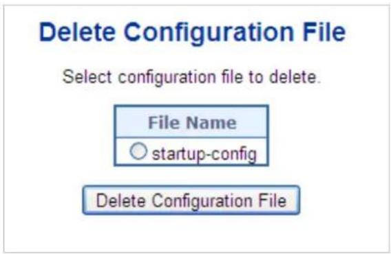
Figure 4-7-1-8: Configuration Delete Page Screenshot
4.7.1.7 Image Select
This page provides information about the active and alternate (backup) firmware images in the device, and allows you to revert to the alternate image. The web page displays two tables with information about the active and alternate firmware images. The Image Select screen in Figure 4-7-1-9 appears.

In case the active firmware image is the alternate image, only the "Active Image" table is shown. In this case, the Activate Alternate Image button is also disabled.

- If the alternate image is active (due to a corruption of the primary image or by manual intervention), uploading a new firmware image to the device will automatically use the primary image slot and activate this.
- The firmware version and date information may be empty for older firmware releases. This does not constitute an error.
Software Image Selection
| Active Image | |
| Image | managed |
| Version | v2.440b210610 |
| Date | 2021-06-10T15:29:10+08:00 |
| Alternate Image | |
| Image | managed.bk |
| Version | v2.440b210610 |
| Date | 2021-06-10T15:29:10+08:00 |
Activate Alternate Image
Figure 4-7-1-9: Software Image Selection Page Screenshot
The page includes the following fields:
| Object Description | |
| • Image | The flash index name of the firmware image. The name of primary (preferred) image is image, the alternate image is named image.bk. |
| • Version | The version of the firmware image. |
| • Date | The date when the firmware was produced. |
Buttons
Activate Alternate Image
Click to use the alternate image. This button may be disabled depending on system state.
4.7.1.8 Factory Default
You can reset the configuration of the Managed Metro Switch on this page. Only the IP configuration is retained. The new configuration is available immediately, which means that no restart is necessary. The Factory Default screen in Figure 4-7-1-10 appears.
Factory Defaults
Are you sure to reset the configuration to Factory Defaults?
The default configuration here doesn't involve IP address.
You can reset configuration included IP by means of pushing the reset button on the machine.

Figure 4-7-1-10: Factory Default Page Screenshot
Buttons

Click to reset the configuration to Factory Defaults.

Click to return to the Port State page without resetting the configuration.

To reset the Managed Metro Switch to the Factory default setting, you can also press the hardware reset button on the front panel for about 10 seconds. After the device is rebooted, you can log in the management Web interface within the same subnet of 192.168.0.xx.
4.7.1.9 System Reboot
The Reboot page enables the device to be rebooted from a remote location. Once the Reboot button is pressed, user has to re-log in the Web interface about 60 seconds later; the System Reboot screen in Figure 4-7-1-11 appears.
Restart Device
Are you sure you want to perform a Restart?

Figure 4-7-1-11: System Reboot Page Screenshot
Buttons

Click to reboot the system.

Click to return to the Port State page without rebooting the system.
4.7.2 Diagnostics
This section provides the Physical layer and IP layer network diagnostics tools for troubleshooting. The diagnostic tools are designed for network manager to help them quickly diagnose problems between point to point and better service customers.
Use the Diagnostics menu items to display and configure basic administrative details of the Managed Metro Switch. Under System the following topics are provided to configure and view the system information:
This section has the following items:
■ Ping
■ IPv6 Ping
■ Remote IP Ping
■ Cable Diagnostics
■ Tracerouter (IPv4)
■ Tracerouter (IPv6)
Ping
The ping and IPv6 ping allow you to issue ICMP PING packets to troubleshoot IP connectivity issues. The Managed Metro Switch transmit ICMP packets, and the sequence number and roundtrip time are displayed upon reception of a reply.
Cable Diagnostics
The Cable Diagnostics performing tests on copper cables. These functions have the ability to identify the cable length and operating conditions, and to isolate a variety of common faults that can occur on the Cat5 twisted-pair cabling. There might be two statuses as follow:
If the link is established on the twisted-pair interface in 1000BASE-T mode, the Cable Diagnostics can run without disruption of the link or of any data transfer.
If the link is established in 100BASE-TX or 10BASE-T, the Cable Diagnostics cause the link to drop while the diagnostics are running.
After the diagnostics are finished, the link is reestablished. And the following functions are available.
■ Coupling between cable pairs.
■ Cable pair termination
■ Cable Length
Traceroute (IPv4)
This page allows you to perform a traceroute test over IPv4 towards a remote host. traceroute is a diagnostic tool for displaying the route and measuring transit delays of packets across an IPv4 network.
Traceroute (IPv6)
This page allows you to perform a traceroute test over IPv6 towards a remote host. traceroute is a diagnostic tool for displaying the route and measuring transit delays of packets across an IPv6 network.
4.7.2.1 Ping
This page allows you to issue ICMP PING packets to troubleshoot IP connectivity issues.
After you press "Start", 5 ICMP packets are transmitted, and the sequence number and roundtrip time are displayed upon reception of a reply. The page refreshes automatically until responses to all packets are received, or until a timeout occurs. The ICMP Ping screen in Figure 4-7-2-1 appears.
Ping (IPv4)
Fill in the parameters as needed and press "Start" to initiate the Ping session.
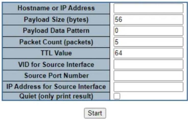
Figure 4-7-2-1: ICMP Ping Page Screenshot
The page includes the following fields:
| Object Description | |
| • Hostname or IP Address | The address of the destination host, either as a symbolic hostname or an IP Address. |
| • Payload Size (bytes) | Determines the size of the ICMP data payload in bytes (excluding the size of Ethernet, IP and ICMP headers). The default value is 56 bytes. The valid range is 2-1452 bytes. |
| • Payload Data Pattern | Determines the pattern used in the ICMP data payload. The default value is 0. The valid range is 0-255. |
| • Packet Count (packets) | Determines the number of PING requests sent. The default value is 5. The valid range is 1-60. |
| • TTL Value | Determines the Time-To-Live /TTL) field value in the IPv4 header. The default value is 64. The valid range is 1-255. |
| • VID for Source Interface | This field can be used to force the test to use a specific local VLAN interface as the source interface. Leave this field empty for automatic selection based on routing configuration.Note: You may only specify either the VID or the IP Address for the source interface. |
| Source Port Number | This field can be used to force the test to use a specific local interface with the specified port number as the source interface. The specified port must be configured with a suitable IP address. Leave this field empty for automatic selection based on routing configuration.Note: You may only specify either the Source Port Number or the IP Address for the source interface. |
| IP Address for Source Interface | This field can be used to force the test to use a specific local interface with the specified IP address as the source interface. The specified IP address must be configured on a local interface. Leave this field empty for automatic selection based on routing configuration.Note: You may only specify either the VID or the IP Address for the source interface. |
| Quiet (only print result) | Checking this option will not print the result of each ping request but will only show the final result. |

Be sure the target IP Address is within the same network subnet of the Managed Metro Switch, or you had setup the correct gateway IP address.
Button
Start
Click to transmit ICMP packets.
4.7.2.2 IPv6 Ping
This page allows you to issue ICMPv6 ping packets to troubleshoot IPv6 connectivity issues. After you press "Start", 5 ICMPv6 packets are transmitted, and the sequence number and roundtrip time are displayed upon reception of a reply. The page refreshes automatically until responses to all packets are received, or until a timeout occurs. The ICMPv6 ping screen in Figure 4-7-2-2 appears.
Ping (IPv6)
Fill in the parameters as needed and press "Start" to initiate the Ping session.
| Hostname or IP Address | |
| Payload Size (bytes) | 56 |
| Payload Data Pattern | 0 |
| Packet Count (packets) | 5 |
| VID for Source Interface | |
| Source Port Number | |
| IP Address for Source Interface | |
| Quiet (only print result) | ☐ |
Start
Figure 4-7-2-2: ICMPv6 Ping Page Screenshot
The page includes the following fields:
| Object Description | |
| • Hostname or IP Address | The address of the destination host, either as a symbolic hostname or an IP Address. |
| • Payload Size (bytes) | Determines the size of the ICMP data payload in bytes (excluding the size of Ethernet, IP and ICMP headers). The default value is 56 bytes. The valid range is 2-1452 bytes. |
| • Payload Data Pattern | Determines the pattern used in the ICMP data payload. The default value is 0. The valid range is 0-255. |
| • Packet Count (packets) | Determines the number of PING requests sent. The default value is 5. The valid range is 1-60. |
| • VID for Source Interface | This field can be used to force the test to use a specific local VLAN interface as the source interface. Leave this field empty for automatic selection based on routing configuration.Note: You may only specify either the VID or the IP Address for the source interface. |
| • Source Port Number | This field can be used to force the test to use a specific local interface with the specified port number as the source interface. The specified port must be configured with a suitable IP address. Leave this field empty for automatic selection based on routing configuration.Note: You may only specify either the Source Port Number or the IPAddress for the source interface. |
| • IP Address for Source Interface | This field can be used to force the test to use a specific local interface with the specified IP address as the source interface. The specified IP address must be configured on a local interface. Leave this field empty for automatic selection based on routing configuration.Note: You may only specify either the VID or the IP Address for the source interface. |
| • Quiet (only print result) | Checking this option will not print the result of each ping request but will only show the final result. |

Be sure the target IP Address is within the same network subnet of the Managed Metro Switch, or you had setup the correct gateway IP address.
Button
Start
Click to transmit ICMP packets.
4.7.2.3 Remote IP Ping
This page allows you to issue ICMP ping packets to troubleshoot IP connectivity issues on special port. After you press "Test", 5 ICMP packets are transmitted, and the sequence number and roundtrip time are displayed upon reception of a reply. The page refreshes automatically until responses to all packets are received, or until a timeout occurs. The ICMP ping screen in Figure 4-7-2-3 appears.
Remote IP Ping Test
| Port | Remote IP Address | Ping Size | Ping Button | Result |
| 1 | 0.0.0.0 | 64 | Ping | |
| 2 | 0.0.0.0 | 64 | Ping | |
| 3 | 0.0.0.0 | 64 | Ping | |
| 4 | 0.0.0.0 | 64 | Ping | |
| 5 | 0.0.0.0 | 64 | Ping | |
| 6 | 0.0.0.0 | 64 | Ping | |
| 7 | 0.0.0.0 | 64 | Ping | |
| 8 | 0.0.0.0 | 64 | Ping | |
| 9 | 0.0.0.0 | 64 | Ping | |
| 10 | 0.0.0.0 | 64 | Ping |

Figure 4-7-2-3: Remote IP Ping Test Page Screenshot
The page includes the following fields:
| Object Description | |
| • Port | The logical port for the settings. |
| • Remote IP Address | This is an IP address of the remote device. |
| • Ping Size | The payload size of the ICMP packet. Values range from 8 bytes to 1400 bytes. |
| • Ping Button | This is a button for you to send 5 ICMP ping packets to the remote device. |
| • Result | Display the ping result. |
Buttons
Apply
: Click to apply changes
Reset
: Click to undo any changes made locally and revert to previously saved values.
Clear
: Clears the IP Address and the result of ping value.
4.7.2.4 Cable Diagnostics
This page is used for running the Cable Diagnostics.
Press to run the diagnostics. This will take approximately 5 seconds. If all ports are selected, this can take approximately 15 seconds. When completed, the page refreshes automatically, and you can view the cable diagnostics results in the cable status table. Note that Cable Diagnostics is only accurate for cables of length 7 - 140 meters.
10 and 100 Mbps ports will be linked down while running cable diagnostic. Therefore, running cable diagnostic on a 10 or 100 Mbps management port will cause the switch to stop responding until VeriPHY is complete. The VeriPHY Cable Diagnostics screen in Figure 4-7-2-4 appears.
VeriPHY Cable Diagnostics
Note:
We recommend to use 1000BASE-T link for web management instead of 10/100BASE-TX link when switch performs cable diagnostic function.

| Cable Status | |||||||||
| Port | Description | Pair A(1,2) | Length A | Pair B(3,6) | Length B | Pair C(4,5) | Length C | Pair D(7,8) | Length D |
| 9 | -- | -- | -- | -- | -- | -- | -- | -- | |
| 10 | -- | -- | -- | -- | -- | -- | -- | -- | |

Figure 4-7-2-4: VeriPHY Cable Diagnostics Page Screenshot
The page includes the following fields:
| Object Description | |
| • Port | The port where you are requesting Cable Diagnostics. |
| • Description | Display per port description. |
| • Cable Status | Port:Port number.Pair:The status of the cable pair.OK - Correctly terminated pairOpen - Open pairUnknown - status is unknown because of many noises during cable detection.Length:The length (in meters) of the cable pai |
Button
Start
Click to run the diagnostics.
4.7.2.5 Tracerouter(IPv4)
This page allows you to perform a traceroute test over IPv4 towards a remote host. traceroute is a diagnostic tool for displaying the route and measuring transit delays of packets across an IPv4 network.
You can configure the following parameters for the test. The traceroute (IPv4) screen in Figure 4-7-2-5 appears.
Traceroute (IPv4)
Fill in the parameters as needed and press "Start" to initiate the Traceroute session.
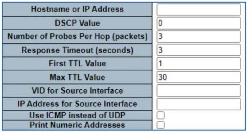
Start
Figure 4-7-2-5: Traceroute (IPv4) Page Screenshot
The page includes the following fields:
| Object Description | |
| • Hostname or IP Address | The destination IP Address. |
| • DSCP Value | This value is used for the DSCP value in the IPv4 header. The default value is 0. The valid range is 0-63. |
| • Number of Probes Per Hop (packets) | Determines the number of probes (packets) sent for each hop. The default value is 3. The valid range is 1-60. |
| • Response Timeout (seconds) | Determines the number of seconds to wait for a reply to a sent request. The default number is 3. The valid range is 1-86400. |
| • First TTL Value | Determines the value of the Time-To-Live (TTL) field in the IPv4 header in the first packet sent. The default number is 1. The valid range is 1-30. |
| • Max TTL Value | Determines the maximum value of the Time-To-Live (TTL) field in the IPv4 header. If this value is reached before the specified remote host is reached the test stops. The default number is 30. The valid range is 1-255. |
| • VID for Source Interface | This field can be used to force the test to use a specific local VLAN interface as the source interface. Leave this field empty for automatic selection based on routing configuration.Note: You may only specify either the VID or the IP Address for the source interface. |
| IP Address for Source Interface | This field can be used to force the test to use a specific local interface with the specified IP address as the source interface. The specified IP address must be configured on a local interface. Leave this field empty for automatic selection based on routing configuration.Note: You may only specify either the VID or the IP Address for the source interface. |
| Use ICMP instead of UDP | By default the traceroute command will use UDP datagrams. Selecting this option forces it to use ICMP ECHO packets instead. |
| Print Numeric Addresses | By default the traceroute command will print out hop information using a reverse DNS lookup for the acquired host ip addresses. This may slow down the display if the DNS information is not available. Selecting this option will prevent the reverse DNS lookup and force the traceroute command to print numeric IP addresses instead. |
Button
Start
Click to run the diagnostics.
4.7.2.6 Tracerouter(IPv6)
This page allows you to perform a traceroute test over IPv6 towards a remote host. traceroute is a diagnostic tool for displaying the route and measuring transit delays of packets across an IPv6 network.
You can configure the following parameters for the test: The traceroute (IPv6) screen in Figure 4-7-2-6 appears.
Traceroute (IPv6)
Fill in the parameters as needed and press "Start" to initiate the Traceroute session.
| Hostname or IP Address | |
| DSCP Value | 0 |
| Number of Probes Per Hop (packets) | 3 |
| Response Timeout (seconds) | 3 |
| Max TTL Value | 30 |
| VID for Source Interface | |
| IP Address for Source Interface | |
| Print Numeric Addresses |
Start
Figure 4-7-2-6: Traceroute (IPv6) Page Screenshot
The page includes the following fields:
| Object Description | |
| • Hostname or IP Address | The destination IP Address. |
| • DSCP Value | This value is used for the DSCP value in the IPv4 header. The default value is 0. The valid range is 0-255. |
| • Number of Probes Per Hop (packets) | Determines the number of probes (packets) sent for each hop. The default value is 3. The valid range is 1-60. |
| • Response Timeout (seconds) | Determines the number of seconds to wait for a reply to a sent request. The default number is 3. The valid range is 1-86400. |
| • Max TTL Value | Determines the maximum value of the Time-To-Live (TTL) field in the IPv4 header. If this value is reached before the specified remote host is reached the test stops. The default number is 255. The valid range is 1-255. |
| • VID for Source Interface | This field can be used to force the test to use a specific local VLAN interface as the source interface. Leave this field empty for automatic selection based on routing configuration.Note: You may only specify either the VID or the IP Address for the source interface. |
| • IP Address for Source Interface | This field can be used to force the test to use a specific local interface with the specified IP address as the source interface. The specified IP address must be configured on a local interface. Leave this field empty for automaticselection based on routing configuration.Note: You may only specify either the VID or the IP Address for the source interface. |
| • Print Numeric Addresses | By default thetraceroutecommand will print out hop information using a reverse DNS lookup for the acquired host ip addresses. This may slow down the display if the DNS information is not available. Selecting this option will prevent the reverse DNS lookup and force thetraceroutecommand to print numeric IP addresses instead. |
Button
Start
Click to run the diagnostics.
5. COMMAND LINE MODE
The CLI groups all the commands in appropriate modes according to the nature of the command. A sample of the CLI command modes are described below. Each of the command modes supports specific software commands.
EXEC mode Command List
| clear Clear | |
| configure | Enter configuration mode |
| copy | Copy from source to destination |
| delete | Delete one file in flash: file system |
| dir | Directory of all files in flash: file system |
| disable | Turn off privileged commands |
| do | To run exec commands in the configuration mode |
| dot1x | IEEE Standard for port-based Network Access Control |
| enable | Turn on privileged commands |
| erps | Ethernet Ring Protection Switching |
| exit Exit from EXEC mode | |
| firmware | Firmware upgrade/swap |
| help | Description of the interactive help system |
| ip | IPv4 commands |
| ipv6 | IPv6 configuration commands |
| link-oam | Link OAM configuration |
| logout | Exit from EXEC mode |
| more | Display file |
| no Delete trace hunt string | |
| ping | Send ICMP echo messages |
| reload | Reload system. |
| send | Send a message to other tty lines |
| show | Display statistics counters. |
| terminal | Set terminal line parameters |
| traceroute | Send IP Traceroute messages |
| veriphy | VeriPHY keyword |
Configuration mode Command List
| aaa | Authentication, Authorization and Accounting |
| access Access management | |
| access-list | Access list |
| aggregation Aggregation mode | |
| alarm Alarm command. | |
| banner Define a banner | |
| clock | Configure time-of-day clock |
| default | Set a command to its defaults |
| do | To run exec commands in the configuration mode |
| dot1x | IEEE Standard for port-based Network Access Control |
| enable | Modify enable password parameters |
| end Go back to EXEC mode | |
| erps | Ethernet Ring Protection Switching |
| exit | Exit from current mode |
| help | Description of the interactive help system |
| hostname | Set system's network name |
| interface | Select an interface to configure |
| ip | Interface Internet Protocol configuration commands |
| ipmc | IPv4/IPv6 multicast configuration |
| ipv6 | IPv6 configuration commands |
| lapc | LACP settings |
| line | Configure a terminal line |
| lldp | Link Layer Discover Protocol. |
| logging | System logging message |
| loop-protect | Loop protection configuration |
| mac | MAC table entries/configuration |
| mep | Maintenance Entity Point |
| monitor | Monitoring different system events |
| mvr | Multicast VLAN Registration configuration |
| mvrp | Enable MVRP feature globally |
| nms | Enable and set the switch*s NMS agent operation mode configuration. |
| no | Negate a command or set its defaults |
| ntp | Configure NTP |
| port-security | This command is obsolete. |
| privilege | Command privilege parameters |
| prompt | Set prompt |
| ptp | Precision time Protocol (1588) |
| qos Quality of | Service |
| radius-server | Configure RADIUS |
| rmon Remote | Monitoring |
| sfp | Set a lower high temperature threshold for the secondary temperature alarm in degrees C. |
| snmp-server | Set SNMP server's configurations |
| spanning-tree | Spanning Tree protocol |
| switchport | Set VLAN switching mode characteristics |
| tacacs-server | Configure TACACS+ |
| transport | Enable or disable transport email function. |
| udld | Enable UDLD in the aggressive or normal mode and to set the configurable message timer on all fiber-optic ports. |
| upnp Set UPnP configuration | |
| username | Establish User Name Authentication |
| vlan | VLAN commands |
| voice | Voice appliance attributes |
| web | Web |
6. SWITCH OPERATION
6.1 Address Table
The Managed Metro Switch is implemented with an address table. This address table is composed of many entries. Each entry is used to store the address information of some nodes in the network, including MAC address, port no, etc. This information comes from the learning process of Managed Metro Switch.
6.2 Learning
When one packet comes in from any port, the Managed Metro Switch will record the source address, port no., and the other related information in address table. This information will be used to decide either forwarding or filtering for future packets.
6.3 Forwarding & Filtering
When one packet comes from some port of the Managed Metro Switch, it will also check the destination address besides the source address learning. The Managed Metro Switch will look up the address-table for the destination address. If not found, this packet will be forwarded to all the other ports except the port, which this packet comes in. And these ports will transmit this packet to the network it connected. If found, and the destination address is located at a different port from this packet comes in, the Managed Metro Switch will forward this packet to the port where this destination address is located according to the information from address table. But, if the destination address is located at the same port with this packet comes in, then this packet will be filtered, thereby increasing the network throughput and availability.
6.4 Store-and-Forward
Store-and-Forward is one type of packet-forwarding techniques. A Store-and-Forward Managed Metro Switch stores the incoming frame in an internal buffer and do the complete error checking before transmission. Therefore, no error packets occur; it is the best choice when a network needs efficiency and stability.
The Managed Metro Switch scans the destination address from the packet-header, searches the routing table provided for the incoming port and forwards the packet, only if required. The fast forwarding makes the switch attractive for connecting servers directly to the network, thereby increasing throughput and availability. However, the switch is most commonly used to segment existence hubs, which nearly always improves the overall performance. An Ethernet switching can be easily configured in any Ethernet network environment to significantly boost bandwidth using the conventional cabling and adapters.
Due to the learning function of the Managed Metro Switch, the source address and corresponding port number of each incoming and outgoing packet are stored in a routing table. This information is subsequently used to filter packets whose destination address is in the same segment as the source address. This confines network traffic to its respective domain and reduce the overall load on the network.
The Managed Metro Switch performs "Store and Fforward"; therefore, no error packets occur. More reliably, it reduces the re-transmission rate. No packet loss will occur.
6.5 Auto-Negotiation
The STP ports on the Switch have built-in "Auto-negotiation". This technology automatically sets the best possible bandwidth when a connection is established with another network device (usually at Power On or Reset). This is done by detecting the modes and speeds both connected devices are capable of. Both 10BASE-T and 100BASE-TX devices can connect with the port in either half- or full-duplex mode. 1000BASE-T can be only connected in full-duplex mode.
7. TROUBLESHOOTING
This chapter contains information to help you solve issues. If the Managed Metro Switch is not functioning properly, make sure the Managed Metro Switch was set up according to instructions in this manual.
■ The Link LED is not lit.
Solution:
Check the cable connection and remove duplex mode of the Managed Metro Switch.
■ Some stations cannot talk to other stations located on the other port.
Solution:
Please check the VLAN settings, trunk settings, or port enabled/disabled status.
■ Performance is bad.
Solution:
Check the full duplex status of the Managed Metro Switch. If the Managed Metro Switch is set to full duplex and the partner is set to half duplex, then the performance will be poor. Please also check the in/out rate of the port.
Why the Switch doesn't connect to the network.
Solution:
- Check the LNK/ACT LED on the switch.
- Try another port on the Switch.
- Make sure the cable is installed properly.
- Make sure the cable is the right type.
- Turn off the power. After a while, turn on power again.
■ 1000BASE-T port link LED is lit, but the traffic is irregular.
Solution:
Check that the attached device is not set to dedicated full duplex. Some devices use a physical or software switch to change duplex modes. Auto-negotiation may not recognize this type of full-duplex setting.
■ Switch does not power up.
Solution:
- AC power cord is not inserted or faulty.
- Check that the AC power cord is inserted correctly.
- Replace the power cord if the cord is inserted correctly; check that the AC power source is working by connecting a different device in place of the switch.
- If that device works, refer to the next step.
- If that device does not work, check the AC power.
APPENDIX A: Networking Connection
A.1 Switch's Data RJ45 Pin Assignments - 1000Mbps, 1000BASE-T
| PIN NO | MDI | MDI-X |
| 1 | BI_DA+ | BI_DB+ |
| 2 BI_DA- | BI_DB- | |
| 3 BI_DB+ | BI_DA+ | |
| 4 BI_DC+ | BI_DD+ | |
| 5 | BI_DC- | BI_DD- |
| 6 BI_DB- | BI_DA- | |
| 7 BI_DD+ | BI_DC+ | |
| 8 BI_DD- | BI_DC- |
Implicit implementation of the crossover function within a twisted-pair cable, or at a wiring panel, while not expressly forbidden, is beyond the scope of this standard.
A.2 10/100Mbps, 10/100BASE-TX
When connecting your Switch to another Fast Ethernet switch, a bridge or a hub, a straight or crossover cable is necessary. Each port of the Switch supports auto-MDI/MDI-X detection. That means you can directly connect the Switch to any Ethernet devices without making a crossover cable. The following table and diagram show the standard RJ45 receptacle/connector and their pin assignments:
| RJ45 Connector pin assignment | ||
| PIN NO | MDIMedia Dependent Interface | MDI-XMedia Dependent Interface - Cross |
| 1 | Tx + (transmit) Rx + (receive) | |
| 2 | Tx - (transmit) | Rx - (receive) |
| 3 | Rx + (receive) Tx + (transmit) | |
| 4, 5 | Not used | |
| 6 | Rx - (receive) | Tx - (transmit) |
| 7, 8 | Not used | |
The standard cable, RJ45 pin assignment
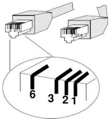
The standard RJ45 receptacle/connector
There are 8 wires on a standard UTP/STP cable and each wire is color-coded. The following shows the pin allocation and color of straight-through cable and crossover cable connection:
| Straight-through Cable | SIDE 1 | SIDE 2 | |
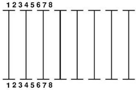 | SIDE 1 | 1 = White / Amber2 = Amber3 = White / Green4 = Blue5 = White / Blue6 = Green7 = White / Brown8 = Brown | 1 = White / Amber2 = Amber3 = White / Green4 = Blue5 = White / Blue6 = Green7 = White / Brown8 = Brown |
| SIDE 2 | |||
| Crossover Cable | SIDE 1 | SIDE 2 | |
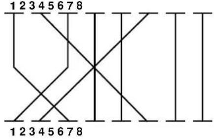 | SIDE 1 | 1 = White / Amber2 = Amber3 = White / Green4 = Blue5 = White / Blue6 = Green7 = White / Brown8 = Brown | 1 = White / Green2 = Green3 = White / Amber4 = Blue5 = White / Blue6 = Amber7 = White / Brown8 = Brown |
| SIDE 2 |
Figure A-1: Straight-through and Crossover Cable
Please make sure your connected cables are with the same pin assignment and color as the above picture before deploying the cables into your network.
APPENDIX B : GLOSSARY
A
ACE
ACE is an acronym for Access Control Entry. It describes access permission associated with a particular ACE ID.
There are three ACE frame types (Ethernet Type, ARP, and IPv4) and two ACE actions (permit and deny).
The ACE also contains many detailed, different parameter options that are available for individual application.
ACL
ACL is an acronym for Access Control List. It is the list table of ACEs, containing access control entries that specify individual users or groups permitted or denied to specific traffic objects, such as a process or a program.
Each accessible traffic object contains an identifier to its ACL. The privileges determine whether there are specific traffic object access rights.
ACL implementations can be quite complex, for example, when the ACEs are prioritized for the various situation. In networking, the ACL refers to a list of service ports or network services that are available on a host or server, each with a list of hosts or servers permitted or denied to use the service. ACL can generally be configured to control inbound traffic, and in this context, they are similar to firewalls.
There are 3 web pages associated with the manual ACL configuration:
ACL|Access Control List: The web page shows the ACEs in a prioritized way, highest (top) to lowest (bottom). Default the table is empty. An ingress frame will only get a hit on one ACE even though there are more matching ACEs. The first matching ACE will take action (permit/deny) on that frame and a counter associated with that ACE is incremented. An ACE can be associated with a policy, 1 ingress port, or any ingress port (the whole switch). If an ACE Policy is created then that policy can be associated with a group of ports under the "Ports" web page. There are number of parameters that can be configured with an ACE. Read the web page help text to get further information for each of them. The maximum number of ACEs is 64.
ACL|Ports: The ACL Port configuration is used to assign a Policy ID to an ingress port. This is useful to group ports to obey the same traffic rules. Traffic Policy is created under the "Access Control List". You can you also set up specific traffic properties (Action / Rate Limiter / Port copy, etc) for each ingress port. They will though only apply if the frame gets past the ACE matching without getting matched. In that case a counter associated with that port is incremented. See the web page help text for each specific port property.
ACL|Rate Limiters: On this page, you can configure the rate limiters. There can be 15 different rate limiters, each ranging from 1 to 1024K packets per second. Under "Ports" and "Access Control List", you can assign a Rate Limiter ID to the ACE(s) or ingress port(s).
AES
standard to improve WLAN security. It is an encryption standard by the U.S. government, which will replace DES and 3DES. AES has a fixed block size of 128 bits and a key size of 128, 192, or 256 bits.
AMS
AMS is an acronym for Auto Media Select. AMS is used for dual media ports (ports supporting both copper (cu) and fiber (SFP) cables. AMS automatically determines if an SFP or a CU cable is inserted and switches to the corresponding media. If both SFP and cu cables are inserted, the port will select the preferred media.
APS
APS is an acronym for Automatic Protection Switching. This protocol is used to secure switching that is done bidirectional in both ends of a protection group, as defined in G.8031.
Aggregation
Using multiple ports in parallel to increase the link speed beyond the limits of a port and to increase the redundancy for higher availability.
(Also Port Aggregation, Link Aggregation).
ARP
ARP is an acronym for Address Resolution Protocol. It is a protocol that used to convert an IP address into a physical address, such as an Ethernet address. ARP allows a host to communicate with other hosts when only the Internet address of its neighbors is known. Before using IP, the host sends a broadcast ARP request containing the Internet address of the desired destination system.
ARP Inspection
ARP Inspection is a secure feature. Several types of attacks can be launched against a host or devices connected to Layer 2 networks by "poisoning" the ARP caches. This feature is used to block such attacks. Only valid ARP requests and responses can go through the switch device.
Auto-Negotiation
Auto-negotiation is the process where two different devices establish the mode of operation and the speed settings that can be shared by those devices for a link.
C
CC
CC is an acronym for Continuity Check. It is a MEP functionality that is able to detect loss of continuity in a network by transmitting CCM frames to a peer MEP.
CCM
CCM is an acronym for Continuity Check Message. It is a OAM frame transmitted from a MEP to its peer MEP and used to implement CC functionality.
CDP
CDP is an acronym for Cisco Discovery Protocol.
D
DEI
DEI is an acronym for Drop Eligible Indicator. It is a 1-bit field in the VLAN tag.
DES
DES is an acronym for Data Encryption Standard. It provides a complete description of a mathematical algorithm for encrypting (enciphering) and decrypting (deciphering) binary coded information.
Encrypting data converts it to an unintelligible form called cipher. Decrypting cipher converts the data back to its original form called plaintext. The algorithm described in this standard specifies both enciphering and deciphering operations which are based on a binary number called a key.
DHCP
DHCP is an acronym for Dynamic Host Configuration Protocol. It is a protocol used for assigning dynamic IP addresses to devices on a network.
DHCP used by networked computers (clients) to obtain IP addresses and other parameters such as the default gateway, subnet mask, and IP addresses of DNS servers from a DHCP server.
The DHCP server ensures that all IP addresses are unique, for example, no IP address is assigned to a second client while the first client's assignment is valid (its lease has not expired). Therefore, IP address pool management is done by the server and not by a human network administrator.
Dynamic addressing simplifies network administration because the software keeps track of IP addresses rather than requiring an administrator to manage the task. This means that a new computer can be added to a network without the hassle of manually assigning it a unique IP address.
DHCP Relay
DHCP Relay is used to forward and to transfer DHCP messages between the clients and the server when they are not on the same subnet domain.
The DHCP option 82 enables a DHCP relay agent to insert specific information into a DHCP request packets when forwarding client DHCP packets to a DHCP server and remove the specific information from a DHCP reply packets when forwarding server DHCP packets to a DHCP client. The DHCP server can use this information to implement IP address or other assignment policies. Specifically the option works by setting two sub-options: Circuit ID (option 1) and Remote ID (option2). The Circuit ID sub-option is supposed to include information specific to which circuit the request came in on. The Remote ID sub-option was designed to carry information relating to the remote host end of the circuit.
The definition of Circuit ID in the switch is 4 bytes in length and the format is "vlan_id" "module_id" "port_no". The parameter of "vlan_id" is the first two bytes represent the VLAN ID. The parameter of "module_id" is the third byte for the module ID. The parameter of "port_no" is the fourth byte and it means the port number. The Remote ID is 6 bytes in length, and the value is equal the DHCP relay agents MAC address.
DHCP Snooping
DHCP Snooping is used to block intruder on the untrusted ports of the switch device when it tries to intervene by injecting a bogus DHCP reply packet to a legitimate conversation between the DHCP client and server.
DNS
DNS is an acronym for Domain Name System. It stores and associates many types of information with domain names. Most importantly, DNS translates human-friendly domain names and computer hostnames into computer-friendly IP addresses. For example, the domain name www.example.com might translate to 192.168.0.1.
DoS
DoS is an acronym for Denial of Service. In a denial-of-service (DoS) attack, an attacker attempts to prevent legitimate users from accessing information or services. By targeting at network sites or network connection, an attacker may be able to prevent network users from accessing email, web sites, online accounts (banking, etc.), or other services that rely on the affected computer.
Dotted Decimal Notation
Dotted Decimal Notation refers to a method of writing IP addresses using decimal numbers and dots as separators between octets.
An IPv4 dotted decimal address has the form x.y.z.w, where x, y, z, and w are decimal numbers between 0 and 255.
DSCP
DSCP is an acronym for Differentiated Services Code Point. It is a field in the header of IP packets for packet classification purposes.
E
EEE
EEE is an abbreviation for Energy Efficient Ethernet defined in IEEE 802.3az.
EPS
EPS is an abbreviation for Ethernet Protection Switching defined in ITU/T G.8031.
Ethernet Type
Ethernet Type, or EtherType, is a field in the Ethernet MAC header, defined by the Ethernet networking standard. It is used to indicate which protocol is being transported in an Ethernet frame.
F
FTP
FTP is an acronym for File Transfer Protocol. It is a transfer protocol that uses the Transmission Control Protocol (TCP) and provides file writing and reading. It also provides directory service and security features.
Fast Leave
IGMP snooping Fast Leave processing allows the switch to remove an interface from the forwarding-table entry without first sending out group specific queries to the interface. The VLAN interface is pruned from the multicast tree for the multicast group specified in the original leave message. Fast-leave processing ensures optimal bandwidth management for all hosts on a switched network, even when multiple multicast groups are in use simultaneously.
H
HTTP
HTTP is an acronym for Hypertext Transfer Protocol. It is a protocol that used to transfer or convey information on the World Wide Web (WWW).
HTTP defines how messages are formatted and transmitted, and what actions Web servers and browsers should take in response to various commands. For example, when you enter a URL in your browser, this actually sends an HTTP command to the Web server directing it to fetch and transmit the requested web page. The other main standard that controls how the World Wide Web works is HTML, which covers how web pages are formatted and displayed.
Any Web server machine contains, in addition to the web page files it can serve, an HTTP daemon, a program that is designed to wait for HTTP requests and handle them when they arrive. The Web browser is an HTTP client, sending requests to server machines. An HTTP client initiates a request by establishing a Transmission Control Protocol (TCP) connection to a particular port on a remote host (port 80 by default). An HTTP server listening on that port waits for the client to send a request message.
HTTPS
HTTPS is an acronym for Hypertext Transfer Protocol over Secure Socket Layer. It is used to indicate a secure HTTP connection.
HTTPS provide authentication and encrypted communication and is widely used on the World Wide Web for security-sensitive communication such as payment transactions and corporate logons.
HTTPS is really just the use of Netscape's Secure Socket Layer (SSL) as a sublayer under its regular HTTP application layering. (HTTPS uses port 443 instead of HTTP port 80 in its interactions with the lower layer, TCP/IP.) SSL uses a 40-bit key size for the RC4 stream encryption algorithm, which is considered an adequate degree of encryption for commercial exchange.
|
ICMP
ICMP is an acronym for Internet Control Message Protocol. It is a protocol that generated the error response, diagnostic or routing purposes. ICMP messages generally contain information about routing difficulties or simple exchanges such as time-stamp or echo transactions. For example, the PING command uses ICMP to test an Internet connection.
IEEE 802.1X
IEEE 802.1X is an IEEE standard for port-based Network Access Control. It provides authentication to devices attached to a LAN port, establishing a point-to-point connection or preventing access from that port if authentication fails. With 802.1X, access to all switch ports can be centrally controlled from a server, which means that authorized users can use the same credentials for authentication from any point within the network.
IGMP
IGMP is an acronym for Internet Group Management Protocol. It is a communications protocol used to manage the
membership of Internet Protocol multicast groups. IGMP is used by IP hosts and adjacent multicast routers to establish multicast group memberships. It is an integral part of the IP multicast specification, like ICMP for unicast connections. IGMP can be used for online video and gaming, and allows more efficient use of resources when supporting these uses.
IGMP Querier
A router sends IGMP Query messages onto a particular link. This router is called the Querier.
IMAP
IMAP is an acronym for Internet Message Access Protocol. It is a protocol for email clients to retrieve email messages from a mail server.
IMAP is the protocol that IMAP clients use to communicate with the servers, and SMTP is the protocol used to transport mail to an IMAP server.
The current version of the Internet Message Access Protocol is IMAP4. It is similar to Post Office Protocol version 3 (POP3), but offers additional and more complex features. For example, the IMAP4 protocol leaves your email messages on the server rather than downloading them to your computer. If you wish to remove your messages from the server, you must use your mail client to generate local folders, copy messages to your local hard drive, and then delete and expunge the messages from the server.
IP
IP is an acronym for Internet Protocol. It is a protocol used for communicating data across a internet network.
IP is a "best effort" system, which means that no packet of information sent over it is assured to reach its destination in the same condition it was sent. Each device connected to a Local Area Network (LAN) or Wide Area Network (WAN) is given an Internet Protocol address, and this IP address is used to identify the device uniquely among all other devices connected to the extended network.
The current version of the Internet protocol is IPv4, which has 32-bits Internet Protocol addresses allowing for in excess of four billion unique addresses. This number is reduced drastically by the practice of webmasters taking addresses in large blocks, the bulk of which remain unused. There is a rather substantial movement to adopt a new version of the Internet Protocol, IPv6, which would have 128-bits Internet Protocol addresses. This number can be represented roughly by a three with thirty-nine zeroes after it. However, IPv4 is still the protocol of choice for most of the Internet.
IPMC
IPMC is an acronym for IP MultiCast.
IP Source Guard
IP Source Guard is a secure feature used to restrict IP traffic on DHCP snooping untrusted ports by filtering traffic based on the DHCP Snooping Table or manually configured IP Source Bindings. It helps prevent IP spoofing attacks when a host tries to spoof and use the IP address of another host.
L
LACP
LACP is an IEEE 802.3ad standard protocol. The Link Aggregation Control Protocol allows bundling several physical ports together to form a single logical port.
LLDP
LLDP is an IEEE 802.1ab standard protocol.
The Link Layer Discovery Protocol(LLDP) specified in this standard allows stations attached to an IEEE 802 LAN to advertise, to other stations attached to the same IEEE 802 LAN, the major capabilities provided by the system incorporating that station, the management address or addresses of the entity or entities that provide management of those capabilities, and the identification of the stations point of attachment to the IEEE 802 LAN required by those management entities. The information distributed via this protocol is stored by its recipients in a standard Management Information Base (MIB), making it possible for the information to be accessed by a Network Management System (NMS) using a management protocol such as the Simple Network Management Protocol (SNMP).
LLDP-MED
LLDP-MED is an extension of IEEE 802.1ab and is defined by the telecommunication industry association (TIA-1057).
LOC
LOC is an acronym for Loss Of Connectivity and is detected by a MEP and is indicating lost connectivity in the network. Can be used as a switch criteria by EPS
M
MAC Table
Switching of frames is based upon the DMAC address contained in the frame. The switch builds up a table that maps MAC addresses to switch ports for knowing which ports the frames should go to (based upon the DMAC address in the frame). This table contains both static and dynamic entries. The static entries are configured by the network administrator if the administrator wants to do a fixed mapping between the DMAC address and switch ports.
The frames also contain a MAC address (SMAC address), which shows the MAC address of the equipment sending the frame. The SMAC address is used by the switch to automatically update the MAC table with these dynamic MAC addresses. Dynamic entries are removed from the MAC table if no frame with the corresponding SMAC address have been seen after a configurable age time.
MEP
MEP is an acronym for Maintenance Entity Endpoint and is an endpoint in a Maintenance Entity Group (ITU-T Y.1731).
MD5
MD5 is an acronym for Message-Digest algorithm 5. MD5 is a message digest algorithm, used cryptographic hash function with a 128-bit hash value. It was designed by Ron Rivest in 1991. MD5 is officially defined in RFC 1321 - The MD5 Message-Digest Algorithm.
Mirroring
For debugging network problems or monitoring network traffic, the switch system can be configured to mirror frames from multiple ports to a mirror port. (In this context, mirroring a frame is the same as copying the frame.) Both incoming (source) and outgoing (destination) frames can be mirrored to the mirror port.
MLD
MLD is an acronym for Multicast Listener Discovery for IPv6. MLD is used by IPv6 routers to discover multicast listeners on a directly attached link, much as IGMP is used in IPv4. The protocol is embedded in ICMPv6 instead of using a separate protocol.
MVR
Multicast VLAN Registration (MVR) is a protocol for Layer 2 (IP)-networks that enables multicast-traffic from a source VLAN to be shared with subscriber-VLANs. The main reason for using MVR is to save bandwidth by preventing duplicate multicast streams being sent in the core network, instead the stream(s) are received on the MVR-VLAN and forwarded to the VLANs where hosts have requested it/them (Wikipedia).
N
NAS
NAS is an acronym for Network Access Server. The NAS is meant to act as a gateway to guard access to a protected source. A client connects to the NAS, and the NAS connects to another resource asking whether the client's supplied credentials are valid. Based on the answer, the NAS then allows or disallows access to the protected resource. An example of a NAS implementation is IEEE 802.1X.
NetBIOS
NetBIOS is an acronym for Network Basic Input/Output System. It is a program that allows applications on separate computers to communicate within a Local Area Network (LAN), and it is not supported on a Wide Area Network (WAN). The NetBIOS giving each computer in the network both a NetBIOS name and an IP address corresponding to a different host name, provides the session and transport services described in the Open Systems Interconnection (OSI) model.
NFS
NFS is an acronym for Network File System. It allows hosts to mount partitions on a remote system and use them as though they are local file systems.
NFS allows the system administrator to store resources in a central location on the network, providing authorized users continuous access to them, which means NFS supports sharing of files, printers, and other resources as persistent storage over a computer network.
NTP
NTP is an acronym for Network Time Protocol, a network protocol for synchronizing the clocks of computer systems. NTP uses UDP (datagrams) as transport layer.
0
OAM
OAM is an acronym for Operation Administration and Maintenance. It is a protocol described in ITU-T Y.1731 used to implement carrier Ethernet functionality. MEP functionality like CC and RDI is based on this.
Optional TLVs.
An LLDP frame contains multiple TLVs. For some TLVs it is configurable if the switch includes the TLV in the LLDP frame. These TLVs are known as optional TLVs. If an optional TLV is disabled the corresponding information is not included in the LLDP frame.
OUI
OUI is the organizationally unique identifier. An OUI address is a globally unique identifier assigned to a vendor by IEEE. You can determine which vendor a device belongs to according to the OUI address which forms the first 24 bits of an MAC address.
P
PCP
PCP is an acronym for Priority Code Point. It is a 3-bit field storing the priority level for the 802.1Q frame. It is also known as User Priority.
PD
PD is an acronym for Powered Device. In a PoE> system the power is delivered from a PSE (power sourcing equipment) to a remote device. The remote device is called a PD.
PHY
PHY is an abbreviation for Physical Interface Transceiver and is the device that implement the Ethernet physical layer (IEEE-802.3).
PING
Ping is a program that sends a series of packets over a network or the Internet to a specific computer in order to generate a response from that computer. The other computer responds with an acknowledgment that it received the packets. Ping was created to verify whether a specific computer on a network or the Internet exists and is connected. Ping uses Internet Control Message Protocol (ICMP) packets. The Ping Request is the packet from the origin computer, and the Ping Reply is the packet response from the target.
Policer
A policer can limit the bandwidth of received frames. It is located in front of the ingress queue.
POP3
POP3 is an acronym for Post Office Protocol version 3. It is a protocol for email clients to retrieve email messages from a mail server.
POP3 is designed to delete mail on the server as soon as the user has downloaded it. However, some implementations allow users or an administrator to specify that mail be saved for some period of time. POP can be thought of as a "store-and-forward" service.
An alternative protocol is Internet Message Access Protocol (IMAP). IMAP provides the user with more capabilities for retaining e-mail on the server and for organizing it in folders on the server. IMAP can be thought of as a remote file server.
POP and IMAP deal with the receiving of e-mail and are not to be confused with the Simple Mail Transfer Protocol (SMTP). You send e-mail with SMTP, and a mail handler receives it on your recipient's behalf. Then the mail is read using POP or IMAP. IMAP4 and POP3 are the two most prevalent Internet standard protocols for e-mail retrieval. Virtually all modern e-mail clients and servers support both.
PPPoE
PPPoE is an acronym for Point-to-Point Protocol over Ethernet. It is a network protocol for encapsulating Point-to-Point Protocol (PPP) frames inside Ethernet frames. It is used mainly with ADSL services where individual users connect to the ADSL transceiver (modem) over Ethernet and in plain Metro Ethernet networks (Wikipedia).
Private VLAN
In a private VLAN, communication between ports in that private VLAN is not permitted. A VLAN can be configured as a private VLAN.
PTP
PTP is an acronym for Precision Time Protocol, a network protocol for synchronizing the clocks of computer systems.
Q
QCE
QCE is an acronym for QoS Control Entry. It describes QoS class associated with a particular QCE ID.
There are six QCE frame types: Ethernet Type, VLAN, UDP/TCP Port, DSCP, TOS, and Tag Priority. Frames can be classified by one of 4 different QoS classes: "Low", "Normal", "Medium", and "High" for individual application.
QCL
QCL is an acronym for QoS Control List. It is the list table of QCEs, containing QoS control entries that classify to a specific QoS class on specific traffic objects.
Each accessible traffic object contains an identifier to its QCL. The privileges determine specific traffic object to specific QoS class.
QL
QL In SyncE this is the Quality Level of a given clock source. This is received on a port in a SSM indicating the quality of the clock received in the port.
QoS
QoS is an acronym for Quality of Service. It is a method to guarantee a bandwidth relationship between individual applications or protocols.
A communications network transports a multitude of applications and data, including high-quality video and delay-sensitive data such as real-time voice. Networks must provide secure, predictable, measurable, and sometimes guaranteed services.
Achieving the required QoS becomes the secret to a successful end-to-end business solution. Therefore, QoS is the set of techniques to manage network resources.
QoS class
Every incoming frame is classified to a QoS class, which is used throughout the device for providing queuing, scheduling and congestion control guarantees to the frame according to what was configured for that specific QoS class. There is a one to one mapping between QoS class, queue and priority. A QoS class of 0 (zero) has the lowest priority.
R
RARP
RARP is an acronym for Reverse Address Resolution Protocol. It is a protocol that is used to obtain an IP address for a given hardware address, such as an Ethernet address. RARP is the complement of ARP.
RADIUS
RADIUS is an acronym for Remote Authentication Dial In User Service. It is a networking protocol that provides centralized access, authorization and accounting management for people or computers to connect and use a network service.
RDI
RDI is an acronym for Remote Defect Indication. It is an OAM functionality that is used by a MEP to indicate defect detected to the remote peer MEP
Router Port
A router port is a port on the Ethernet switch that leads switch towards the Layer 3 multicast device.
RSTP
In 1998, the IEEE with document 802.1w introduced an evolution of STP: the Rapid Spanning Tree Protocol, which provides for faster spanning tree convergence after a topology change. Standard IEEE 802.1D-2004 now incorporates RSTP and obsoletes STP, while at the same time being backwards-compatible with STP.
S
SAMBA
Samba is a program running under UNIX-like operating systems that provides seamless integration between UNIX and Microsoft Windows machines. Samba acts as file and print servers for Microsoft Windows, IBM OS/2, and other SMB
client machines. Samba uses the Server Message Block (SMB) protocol and Common Internet File System (CIFS), which is the underlying protocol used in Microsoft Windows networking. Samba can be installed on a variety of operating system platforms, including Linux, most common Unix platforms, OpenVMS, and IBM OS/2. Samba can also register itself with the master browser on the network so that it would appear in the listing of hosts in Microsoft Windows "Neighborhood Network".
SHA
SHA is an acronym for Secure Hash Algorithm. It designed by the National Security Agency (NSA) and published by the NIST as a U.S. Federal Information Processing Standard. Hash algorithms compute a fixed-length digital representation (known as a message digest) of an input data sequence (the message) of any length.
Shaper
A shaper can limit the bandwidth of transmitted frames. It is located after the ingress queues.
SMTP
SMTP is an acronym for Simple Mail Transfer Protocol. It is a text-based protocol that uses the Transmission Control Protocol (TCP) and provides a mail service modeled on the FTP file transfer service. SMTP transfers mail messages between systems and notifications regarding incoming mail.
SNAP
The SubNetwork Access Protocol (SNAP) is a mechanism for multiplexing, on networks using IEEE 802.2 LLC, more protocols than can be distinguished by the 8-bit 802.2 Service Access Point (SAP) fields. SNAP supports identifying protocols by Ethernet type field values; it also supports vendor-private protocol identifier.
SNMP
SNMP is an acronym for Simple Network Management Protocol. It is part of the Transmission Control Protocol/Internet Protocol (TCP/IP) protocol for network management. SNMP allow diverse network objects to participate in a network management architecture. It enables network management systems to learn network problems by receiving traps or change notices from network devices implementing SNMP.
SNTP
SNTP is an acronym for Simple Network Time Protocol, a network protocol for synchronizing the clocks of computer systems. SNTP uses UDP (datagrams) as transport layer.
SPROUT
Stack Protocol using ROUting Technology. An advanced protocol for almost instantaneous discovery of topology changes within a stack as well as election of a master switch. SPROUT also calculates parameters for setting up each switch to perform shortest path forwarding within the stack.
SSID
Service Set Identifier is a name used to identify the particular 802.11 wireless LANs to which a user wants to attach. A client device will receive broadcast messages from all access points within range advertising their SSIDs, and can choose one to connect to based on pre-configuration, or by displaying a list of SSIDs in range and asking the user to
select one (wikipedia).
SSH
SSH is an acronym for Secure SHell. It is a network protocol that allows data to be exchanged using a secure channel between two networked devices. The encryption used by SSH provides confidentiality and integrity of data over an insecure network. The goal of SSH was to replace the earlier rlogin, TELNET and rsh protocols, which did not provide strong authentication or guarantee confidentiality (Wikipedia).
SSM
SSM In SyncE this is an abbreviation for Synchronization Status Message and is containing a QL indication.
STP
Spanning Tree Protocol is an OSI layer-2 protocol which ensures a loop free topology for any bridged LAN. The original STP protocol is now obsolete by RSTP.
SyncE
SyncE Is an abbreviation for Synchronous Ethernet. This functionality is used to make a network 'clock frequency' synchronized. Not to be confused with real time clock synchronized (IEEE 1588).
T
TACACS+
TACACS+ is an acronym for Terminal Access Controller Access Control System Plus. It is a networking protocol which provides access control for routers, network access servers and other networked computing devices via one or more centralized servers. TACACS+ provides separate authentication, authorization and accounting services.
Tag Priority
Tag Priority is a 3-bit field storing the priority level for the 802.1Q frame.
TCP
TCP is an acronym for Transmission Control Protocol. It is a communications protocol that uses the Internet Protocol (IP) to exchange the messages between computers.
The TCP protocol guarantees reliable and in-order delivery of data from sender to receiver and distinguishes data for multiple connections by concurrent applications (for example, Web server and e-mail server) running on the same host.
The applications on networked hosts can use TCP to create connections to one another. It is known as a connection-oriented protocol, which means that a connection is established and maintained until such time as the message or messages to be exchanged by the application programs at each end have been exchanged. TCP is responsible for ensuring that a message is divided into the packets that IP manages and for reassembling the packets back into the complete message at the other end.
Common network applications that use TCP include the World Wide Web (WWW), e-mail, and File Transfer Protocol (FTP).
TELNET
TELNET is an acronym for Teletype Network. It is a terminal emulation protocol that uses the Transmission Control
Protocol (TCP) and provides a virtual connection between TELNET server and TELNET client.
TELNET enables the client to control the server and communicate with other servers on the network. To start a Telnet session, the client user must log in to a server by entering a valid username and password. Then, the client user can enter commands through the Telnet program just as if they were entering commands directly on the server console.
TFTP
TFTP is an acronym for Trivial File Transfer Protocol. It is transfer protocol that uses the User Datagram Protocol (UDP) and provides file writing and reading, but it does not provide directory service and security features.
Toss
Toss is an acronym for Type of Service. It is implemented as the IPv4 Toss priority control. It is fully decoded to determine the priority from the 6-bit Toss field in the IP header. The most significant 6 bits of the Toss field are fully decoded into 64 possibilities, and the singular code that results is compared against the corresponding bit in the IPv4 ToS priority control bit (0\~63).
TLV
TLV is an acronym for Type Length Value. A LLDP frame can contain multiple pieces of information. Each of these pieces of information is known as TLV.
TKIP
TKIP is an acronym for Temporal Key Integrity Protocol. It used in WPA to replace WEP with a new encryption algorithm. TKIP comprises the same encryption engine and RC4 algorithm defined for WEP. The key used for encryption in TKIP is 128 bits and changes the key used for each packet.
U
UDP
UDP is an acronym for User Datagram Protocol. It is a communications protocol that uses the Internet Protocol (IP) to exchange the messages between computers.
UDP is an alternative to the Transmission Control Protocol (TCP) that uses the Internet Protocol (IP). Unlike TCP, UDP does not provide the service of dividing a message into packet datagrams, and UDP doesn't provide reassembling and sequencing of the packets. This means that the application program that uses UDP must be able to make sure that the entire message has arrived and is in the right order. Network applications that want to save processing time because they have very small data units to exchange may prefer UDP to TCP.
UDP provides two services not provided by the IP layer. It provides port numbers to help distinguish different user requests and, optionally, a checksum capability to verify that the data arrived intact.
Common network applications that use UDP include the Domain Name System (DNS), streaming media applications such as IPTV, Voice over IP (VoIP), and Trivial File Transfer Protocol (TFTP).
UPnP
UPnP is an acronym for Universal Plug and Play. The goals of UPnP are to allow devices to connect seamlessly and to simplify the implementation of networks in the home (data sharing, communications, and entertainment) and in corporate environments for simplified installation of computer components
User Priority
User Priority is a 3-bit field storing the priority level for the 802.1Q frame.
V
VLAN
A method to restrict communication between switch ports. VLANs can be used for the following applications:
VLAN unaware switching: This is the default configuration. All ports are VLAN unaware with Port VLAN ID 1 and members of VLAN 1. This means that MAC addresses are learned in VLAN 1, and the switch does not remove or insert VLAN tags.
VLAN aware switching: This is based on the IEEE 802.1Q standard. All ports are VLAN aware. Ports connected to VLAN aware switches are members of multiple VLANs and transmit tagged frames. Other ports are members of one VLAN, set up with this Port VLAN ID, and transmit untagged frames.
Provider switching: This is also known as Q-in-Q switching. Ports connected to subscribers are VLAN unaware, members of one VLAN, and set up with this unique Port VLAN ID. Ports connected to the service provider are VLAN aware, members of multiple VLANs, and set up to tag all frames. Untagged frames received on a subscriber port are forwarded to the provider port with a single VLAN tag. Tagged frames received on a subscriber port are forwarded to the provider port with a double VLAN tag.
VLAN ID
VLAN ID is a 12-bit field specifying the VLAN to which the frame belongs.
Voice VLAN
Voice VLAN is VLAN configured specially for voice traffic. By adding the ports with voice devices attached to voice VLAN, we can perform QoS-related configuration for voice data, ensuring the transmission priority of voice traffic and voice quality.
W
WEP
WEP is an acronym for Wired Equivalent Privacy. WEP is a deprecated algorithm to secure IEEE 802.11 wireless networks. Wireless networks broadcast messages using radio, so are more susceptible to eavesdropping than wired networks. When introduced in 1999, WEP was intended to provide confidentiality comparable to that of a traditional wired network (Wikipedia).
Wi-Fi
Wi-Fi is an acronym for Wireless Fidelity. It is meant to be used generically when referring of any type of 802.11 network, whether 802.11b, 802.11a, dual-band, etc. The term is promulgated by the Wi-Fi Alliance.
WPA
WPA is an acronym for Wi-Fi Protected Access. It was created in response to several serious weaknesses researchers had found in the previous system, Wired Equivalent Privacy (WEP). WPA implements the majority of the IEEE 802.11i standard, and was intended as an intermediate measure to take the place of WEP while 802.11i was prepared. WPA is
specifically designed to also work with pre-WPA wireless network interface cards (through firmware upgrades), but not necessarily with first generation wireless access points. WPA2 implements the full standard, but will not work with some older network cards (Wikipedia).
WPA-PSK
WPA-PSK is an acronym for Wi-Fi Protected Access - Pre Shared Key. WPA was designed to enhance the security of wireless networks. There are two flavors of WPA: enterprise and personal. Enterprise is meant for use with an IEEE 802.1X authentication server, which distributes different keys to each user. Personal WPA utilizes less scalable 'pre-shared key' (PSK) mode, where every allowed computer is given the same passphrase. In PSK mode, security depends on the strength and secrecy of the passphrase. The design of WPA is based on a Draft 3 of the IEEE 802.11i standard (Wikipedia)
WPA-Radius
WPA-Radius is an acronym for Wi-Fi Protected Access - Radius (802.1X authentication server). WPA was designed to enhance the security of wireless networks. There are two flavors of WPA: enterprise and personal. Enterprise is meant for use with an IEEE 802.1X authentication server, which distributes different keys to each user. Personal WPA utilizes less scalable 'pre-shared key' (PSK) mode, where every allowed computer is given the same passphrase. In PSK mode, security depends on the strength and secrecy of the passphrase. The design of WPA is based on a Draft 3 of the IEEE 802.11i standard (Wikipedia)
WPS
WPS is an acronym for Wi-Fi Protected Setup. It is a standard for easy and secure establishment of a wireless home network. The goal of the WPS protocol is to simplify the process of connecting any home device to the wireless network (Wikipedia).
WRED
WRED is an acronym for Weighted Random Early Detection. It is an active queue management mechanism that provides preferential treatment of higher priority frames when traffic builds up within a queue. A frame's DP level is used as input to WRED. A higher DP level assigned to a frame results in a higher probability that the frame is dropped during times of congestion.
WTR
WTR is an acronym for Wait To Restore. This is the time a fail on a resource has to be 'not active' before restoration back to this (previously failing) resource is done.
- 10-Port Gigabit
- Managed Metro Ethernet Switch
- Trademarks
- Disclaimer
- FCC Warning
- CE Mark Warning
- Energy Saving Note of the Device
- WEEE Warning
- Revision
- TABLE OF CONTENTS
- INTRODUCTION .... 10
- INSTALLATION 24
- SWITCH MANAGEMENT .... 39
- WEB CONFIGURATION.... 46
- Simple Network Management Protocol....82
- RMON 95
- DHCP server ....105
- Remote Management....114
- Switching....116
- Port Management....116
- Link Aggregation....127
- VLAN 138
- Spanning Tree Protocol....171
- Multicast....190
- MLD Snooping....204
- MVR (Multicast VLAN Registration)....212
- LLDP 218
- MAC Address Table....235
- Loop Protection....239
- UDLD 241
- GVRP 244
- Port Authentication....317
- Port Security....327
- Access Control Lists....333
- DHCP Snooping....350
- IP Source Guard 353
- ARP Inspection....356
- Ring 360
- ERPS Ring 360
- Maintenance 377
- Switch Maintenance....377
- Diagnostics....383
- COMMAND LINE MODE 394
- SWITCH OPERATION 397
- TROUBLESHOOTING....399
- APPENDIX A: Networking Connection 400
- APPENDIX B : GLOSSARY 402
- INTRODUCTION
- Packet Contents
- Product Description
- Multiple SFP Fiber Port Switch for Growing Long-Reach Networking of Enterprises, Telecoms and Campuses
- Cybersecurity Network Solution to Minimize Security Risks
- Redundant Ring, Fast Recovery for Critical Network Applications
- AC and DC Redundant Power to Ensure Continuous Operation
- Digital Input and Digital Output for External Alarm
- Digital Input
- Digital Output
- Environmentally-friendly, Fanless Design for Silent Operation
- Cost-effective IPv6 Managed Gigabit Switch Solution for Metro Ethernet
- Robust Layer 2 Features
- Efficient Traffic Control
- Powerful Security
- Friendly and Secure Management
- Flexibility and Extension Solution
- Intelligent SFP Diagnosis Mechanism
- Time Protocol for Industrial Computing Networks
- How to Use This Manual
- Product Features
- Physical Port
- Redundant Power System
- Digital Input / Digital Output
- Industrial Protocol
- Hardware Design
- Layer 2 Features
- ■ Supports VLAN
- ■ Supports Spanning Tree Protocol
- ■ Supports Link Aggregation
- Quality of Service
- Multicast
- Security
- Management
- INSTALLATION
- Hardware Description
- Switch Front Panel
- Front Panel
- ■ AC Power Receptacle
- DC Power Connector
- ■ 100/1000BASE-X SFP Slots (port 1 to port 6)
- ■ 100/1000/2500BASE-X SFP Slots (port 7 to port 8)
- Gigabit TP Interface(port 9 to port 10)
- Console Port
- Reset Button
- LED Indicators
- Wiring the AC Power Input
- Wiring the DC Power Input
- Wiring the Fault Alarm Contact
- Wiring the Digital Input/Output
- Installing the Managed Metro Switch
- Desktop Installation
- Rack Mounting
- Cabling
- ■ 10/100/1000BASE-T
- ■ 100BASE-FX/1000BASE-SX/LX/2500BASE-X
- ■ Cabling
- Installing the SFP Transceiver
- ■ Approved PLANET SFP Transceivers
- Connect the fiber cable
- Removing the SFP Transceiver
- SWITCH MANAGEMENT
- This chapter covers the following topics:
- Requirements
- ■ Ethernet Port Connection
- Management Access Overview
- CLI Mode Management
- Direct Access
- Remote Telnet
- Web Management
- SNMP-based Network Management
- PLANET Smart Discovery Utility
- About Web-based Management
- ■ Logging on the Managed Metro Switch
- Main Web page
- Panel Display
- Main Menu
- System
- Management
- System Information
- Buttons
- IP Configuration
- Add Interface
- Add Route
- Apply
- Reset
- IP Status
- ARP Table
- ARP Table Configuration
- Users Configuration
- Add / Edit User
- Add User
- Privilege Levels
- NTP Configuration
- System Time Correction Manually
- Time Configuration
- UPnP
- DHCP Relay
- DHCP Relay Statistics
- CPU Load
- System Log
- Detailed Log
- Remote Syslog
- SMTP Configuration
- Fault Alarm
- Digital Input/Output
- Simple Network Management Protocol
- SNMP Overview
- SNMP Operations
- SNMP community
- SNMP System Configuration
- SNMP System Information
- SNMP Trap Configuration
- SNMP Trap Source Configuration
- SNMPv3 Communities
- SNMPv3 Users
- Add New Entry
- SNMPv3 Groups
- SNMPv3 Views
- SNMPv3 Access
- RMON
- RMON Alarm Configuration
- RMON Alarm Status
- RMON Event Configuration
- RMON Event Status
- RMON History Configuration
- RMON History Status
- RMON Statistics Configuration
- RMON Statistics Configuration
- RMON Statistics Status
- Refresh
- DHCP server
- DHCP Server Mode Configuration
- Global Mode
- VLAN Mode
- DHCP Server excluded IP Configuration
- DHCP Server pool Configuration
- DHCP Server Statistics
- DHCP Server Statistics
- DHCP Server Binding IP Configuration
- DHCP Server Declined IP
- DHCP Detail Statistics
- Remote Management
- PLANET NMS Controller - LAN
- Switching
- Port Management
- Port Configuration
- Port Statistics Overview
- Port Statistics Detail
- Receive and Transmit Size Counters
- Receive and Transmit Queue Counters
- Receive Error Counters
- Transmit Error Counters
- SFP Module Information
- Port Mirror
- Mirror Port Configuration
- Mirror & RMirror Configuration
- Global Settings
- Port Configuration
- Name Map
- Link Aggregation
- Common Aggregation Configuration
- Common Aggregation Configuration
- Static Aggregation Group Configuration
- Static Aggregation Status
- LACP Configuration
- LACP System Configuration
- LACP Port Configuration
- LACP System Status
- LACP System Status
- LACP Internal Status
- LACP Neighbor Port Status
- LACP Port Statistics
- VLAN
- VLAN Overview
- IEEE 802.1Q VLAN
- IEEE 802.1Q Standard
- 802.1Q VLAN Tags
- Port VLAN ID
- Default VLANs
- - Assigning Ports to VLANs
- VLAN Classification
- Port Overlapping
- ■ Untagged VLANs
- IEEE 802.1Q Tunneling (Q-in-Q)
- VLAN Port Configuration
- Understand nomenclature of the Switch
- IEEE 802.1Q Tagged and Untagged
- Global VLAN Configuration
- Port VLAN Configuration
- VLAN Membership Status
- VLAN Port Status
- Private VLAN
- Port Isolation
- Overview
- ■ Promiscuous ports
- ■ Isolated ports
- Port Isolation Configuration
- VLAN setting example:
- Two Separate 802.1Q VLANs
- ■ Tagged packet entering VLAN 2
- ■ Untagged packet entering VLAN 3
- Setup steps
- Add VLAN Group
- Assign VLAN Member and PVID for each port:
- Enable VLAN Tag for specific ports
- VLAN Trunking between two 802.1Q aware switches
- Assign VLAN Member and PVID for each port :
- Port Isolate
- Assign Port Mode
- MAC-based VLAN
- MAC-based VLAN Membership Configuration
- IP Subnet-based VLAN Membership Configuration
- Protocol-based VLAN
- Protocol-based VLAN Membership
- VLAN Translation
- VLAN Translation Port Configuration
- VLAN Translation Mapping Table
- Spanning Tree Protocol
- Theory
- Bridge Protocol Data Units
- Creating a Stable STP Topology
- STP Port States
- Each port on a switch using STP exists is in one of the following five states:
- A port transitions from one state to another as follows:
- STP Parameters
- STP Operation Levels
- User-Changeable STA Parameters
- Illustration of STP
- STP System Configuration
- Bridge Status
- CIST Port Configuration
- MSTI Priorities
- MSTI Configuration
- MSTI Configuration
- MSTI Mapping
- MSTI Ports Configuration
- MSTI Port Configuration
- MST1 MSTI Port Configuration
- MSTI Aggregated Ports Configuration
- MSTI Normal Ports Configuration
- MSTx MSTI Port Configuration
- Port Status
- Port Statistics
- Multicast
- IGMP Snooping
- About the Internet Group Management Protocol (IGMP) Snooping
- IGMP Versions 1 and 2
- IGMP Message Format
- ■ IGMP Querier –
- Profile Table
- Address Entry
- IGMP Snooping Configuration
- IGMP Snooping Configuration
- Stack Global Settings
- IGMP Snooping VLAN Configuration
- IGMP Snooping Port Group Filtering
- IGMP Snooping Status
- IGMP Snooping Status
- IGMP Groups Information
- IGMPv3 Information
- IGMP SFM Information
- MLD Snooping
- MLD Snooping Configuration
- MLD Snooping VLAN Configuration
- MLD Snooping Port Group Filtering
- MLD Snooping Status
- MLD Snooping Status
- MLD Groups Information
- MLDv2 Information
- MLD SFM Information
- MVR (Multicast VLAN Registration)
- MVR Configuration
- MVR Status
- MVR Groups Information
- MVR SFM Information
- LLDP
- Link Layer Discovery Protocol
- LLDP Configuration
- LLDP Port Configuration
- LLDP Neighbors
- LLDP-MED Configuration
- Civic Address Location
- Emergency Call Service
- Policies
- Port Policies Configuration
- LLDP-MED Neighbors
- Port Statistics
- LLDP Statistics Local Counters
- MAC Address Table
- MAC Table Configuration
- MAC Address Table Configuration
- Aging Configuration
- MAC Table Learning
- Static MAC Table Configuration
- MAC Address Table Status
- Dynamic MAC Table
- Navigating the MAC Table
- Loop Protection
- Configuration
- Loop Protection Configuration
- General Settings
- Loop Protection Status
- UDLD
- UDLD Port Configuration
- Save
- UDLD Status
- Detailed UDLD Status for Port 1
- Neighbour Status
- GVRP
- GVRP Configuration
- GVRP Port Configuration
- PTP
- PTP Configuration
- Clock Type and Profile
- Port Enable and Configuration
- Port Data Set
- Virtual Port Enable and Configuration
- Local Clock Current Time
- Clock current Data Set
- Clock Parent Data Set
- Clock Default Data Set
- Clock Time Properties Data Set
- Link OAM
- Statistics
- Clear
- Port Status
- Event Status
- Port Settings
- Event Settings
- MIB Retrieval
- Link-OAM Example
- Step 1. Set CE as Passive OAM mode
- Step 2. Set PE as Active OAM mode
- Step 3. Check OAM status and statistic from CE device
- Quality of Service
- General
- QoS Terminology
- QoS Port Classification
- Queue Policing
- Port Tag Remarking
- Statistics
- Bandwidth Control
- Port Policing
- Port Schedule
- Port Shaping
- Storm Control
- Storm Policing Configuration
- Differentiated Service
- Port DSCP
- DSCP-based QoS
- DSCP Translation
- DSCP Classification
- QCL
- QoS Control List
- QoS Control Entry Configuration
- QCL Status
- Voice VLAN Configuration
- Voice VLAN OUI Table
- Security
- Access Security
- Access Management
- Access Management Statistics
- SSH
- HTTPS
- AAA
- Overview of 802.1X (Port-Based) Authentication
- Overview of MAC-based Authentication
- Overview of User Authentication
- Understanding IEEE 802.1X Port-based Authentication
- ■ Device Roles
- ■ Authentication Initiation and Message Exchange
- ■ Ports in Authorized and Unauthorized States
- Authentication Configuration
- Authentication Method Configuration
- Command Authorization Method Configuration
- Accounting Method Configuration
- RADIUS
- Global Configuration
- Server Configuration
- Add New Server
- Delete
- TACACS+
- RADIUS Overview
- RADIUS Details
- RADIUS Authentication Statistics
- RADIUS Accounting Statistics
- Port Authentication
- Network Access Server Configuration
- Network Access Overview
- Network Access Statistics
- Port Counters
- Port Security
- Port Limit Control
- Port Security Configuration
- System Configuration
- Port Security Status
- Port Security Switch Status
- User Module Legend
- Port Status
- Port Security Detail
- Port Security Port Status Port 1
- Access Control Lists
- Access Control List Status
- Access Control List Configuration
- ACE Configuration
- ■ MAC Parameters
- ■ VLAN Parameters
- ■ ARP Parameters
- ■ IP Parameters
- ■ Ethernet Type Parameters
- ACL Ports Configuration
- ACL Rate Limiters
- DHCP Snooping
- DHCP Snooping Configuration
- DHCP Snooping Configuration
- Port Mode Configuration
- Snooping Table
- IP Source Guard
- IP Source Guard Configuration
- Static IP Source Guard Table
- Dynamic IP Source Guard Table
- ARP Inspection
- ARP Inspection
- ARP Inspection Static Table
- Dynamic ARP Inspection Table
- Navigating the ARP Inspection Table
- Ring
- ERPS Ring
- MEP Configuration
- Detailed MEP Configuration
- Functional Configuration
- TLV Configuration:
- TLV Status:
- Ethernet Ring Protocol Switch
- Add New Protection Group
- Ethernet Ring Protocol Switch Configuration
- Instant State:
- Ethernet Ring Protocol Switch
- Ring Wizard
- Note:
- Ring Wizard Example
- Set ERPS Configuration on Switch 1
- Set ERPS Configuration on Switch 2
- Set ERPS Configuration on Switch 3
- Maintenance
- Switch Maintenance
- Web Firmware Upgrade
- Firmware Upload
- Save Startup Config
- Save Running Configuration to startup-config
- Configuration Download
- Download Configuration
- File Name
- Configuration Upload
- Configuration Activate
- Activate Configuration
- Configuration Delete
- Image Select
- Factory Default
- Factory Defaults
- System Reboot
- Restart Device
- Diagnostics
- Ping
- Cable Diagnostics
- Traceroute (IPv4)
- Traceroute (IPv6)
- Ping
- Ping (IPv4)
- Button
- IPv6 Ping
- Ping (IPv6)
- Remote IP Ping
- Cable Diagnostics
- VeriPHY Cable Diagnostics
- Tracerouter(IPv4)
- Tracerouter(IPv6)
- COMMAND LINE MODE
- SWITCH OPERATION
- Address Table
- Learning
- Forwarding & Filtering
- Store-and-Forward
- Auto-Negotiation
- TROUBLESHOOTING
- APPENDIX A: Networking Connection
- A.1 Switch's Data RJ45 Pin Assignments - 1000Mbps, 1000BASE-T
- A.2 10/100Mbps, 10/100BASE-TX
- APPENDIX B : GLOSSARY
- A
- ACE
- ACL
- AES
- AMS
- APS
- Aggregation
- ARP
- ARP Inspection
- Auto-Negotiation
- C
- CC
- CCM
- CDP
- D
- DEI
- DES
- DHCP
- DHCP Relay
- DHCP Snooping
- DNS
- DoS
- Dotted Decimal Notation
- DSCP
- E
- EEE
- EPS
- Ethernet Type
- F
- FTP
- Fast Leave
- H
- HTTP
- HTTPS
- |
- ICMP
- IEEE 802.1X
- IGMP
- IGMP Querier
- IMAP
- IP
- IPMC
- IP Source Guard
- L
- LACP
- LLDP
- LLDP-MED
- LOC
- M
- MAC Table
- MEP
- MD5
- Mirroring
- MLD
- MVR
- N
- NAS
- NetBIOS
- NFS
- NTP
- 0
- OAM
- Optional TLVs.
- OUI
- P
- PCP
- PD
- PHY
- Policer
- POP3
- PPPoE
- Private VLAN
- PTP
- Q
- QCE
- QCL
- QL
- QoS
- QoS class
- R
- RARP
- RADIUS
- RDI
- Router Port
- RSTP
- S
- SAMBA
- SHA
- Shaper
- SMTP
- SNAP
- SNMP
- SNTP
- SPROUT
- SSID
- SSH
- SSM
- STP
- SyncE
- T
- TACACS+
- Tag Priority
- TCP
- TELNET
- TFTP
- Toss
- TLV
- TKIP
- U
- UDP
- UPnP
- User Priority
- V
- VLAN
- VLAN ID
- Voice VLAN
- W
- WEP
- Wi-Fi
- WPA
- WPA-PSK
- WPA-Radius
- WPS
- WRED
- WTR
Brand : Planet
Model : MGSD-10080F
Category : Switch