MGS-910XP - Switch Planet - Free user manual and instructions
Find the device manual for free MGS-910XP Planet in PDF.


| Product Type | 8-Port 10/100/1000/2500T + 1-Port 10G SFP+ Multigigabit Ethernet Switch with PoE+ |
| Brand | Planet |
| Model | MGS-910XP |
| Dimensions (W x D x H) | 280 x 180 x 44 mm |
| Weight | 1739 g |
| Power Supply | 100-240V AC, 3A, 50-60Hz |
| Power Consumption | 140 watts (max), 447.6 BTU |
| Network Ports | 8 x RJ45 (10/100/1000/2500BASE-T) + 1 x SFP+ (10GBASE-X) |
| PoE Standard | IEEE 802.3at PoE+ (PSE) |
| PoE Power Budget | 120 watts total |
| PoE Power per Port | Up to 32 watts (802.3at), up to 15.4 watts (802.3af) |
| Switch Fabric | 60 Gbps |
| Forwarding Rate | 44.64 Mpps (64-byte packets) |
| MAC Address Table | 4K entries |
| Jumbo Frame Support | 12K bytes |
| DIP Switch Modes | Standard (all ports communicate) / VLAN (ports 1-8 isolated, communicate only with port 9) |
| LED Indicators | Power (green), 10/100/1000 LNK/ACT (amber), 2500 LNK/ACT (green), 10G SFP+ LNK/ACT (green), PoE-in-Use (amber) |
| Cooling | 1 fan |
| ESD Protection | Contact discharge ±6kV DC, Air discharge ±8kV DC |
| Surge Protection | ±6kV |
| Operating Temperature | 0°C to 50°C |
| Storage Temperature | -10°C to 70°C |
| Operating Humidity | 5% to 95% (non-condensing) |
| Mounting | Desktop or 19-inch rack (brackets included) |
| Regulatory Compliance | FCC Part 15 Class A, CE |
Frequently Asked Questions - MGS-910XP Planet
User questions about MGS-910XP Planet
0 question about this device. Answer the ones you know or ask your own.
Ask a new question about this device
Download the instructions for your Switch in PDF format for free! Find your manual MGS-910XP - Planet and take your electronic device back in hand. On this page are published all the documents necessary for the use of your device. MGS-910XP by Planet.
USER MANUAL MGS-910XP Planet
8-Port 10/100/1000/2500T + 1-Port 10G SFP+
Multigigabit Ethernet Switch
8-Port 10/100/1000/2500T 802.3at PoE+ + 1-Port 10G SFP+
Multigigabit Ethernet Switch (120 Watts)
MGS-910X/MGS-910XP
User's Manual
Table of Contents
- Package Contents......3
- Hardware Introduction 4
2.1 Front Panel 4
2.2 LED Indicators....4
2.3 Multiple Functions of DIP Switch 5
2.4 Switch Rear Panel....7
- Hardware Installation....8
3.1 Rack Mounting....8
3.2 Rack Mounting....9
3.3 Installing the SFP+ Transceiver.... 10
- Product Specifications.... 13
- Physical Dimensions ...... 16
Customer Support.... 18
1. Package Contents
Thank you for purchasing PLANET 8-Port 10/100/1000/2500T Multigigabit Ethernet Switch, MGS-910X or MGS-910XP. "Multigigabit Ethernet Switch" mentioned in this User's Manual refers to the MGS-910X or MGS-910XP.
Open the box of the Multigigabit Ethernet Switch and carefully unpack it. The box should contain the following items:
| Multigigabit Ethernet Switch x 1 | Quick Start QR Code Sheet x 1 | Rack-mounting Brackets x 2 | ||
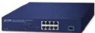 |  | 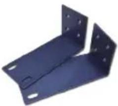 | ||
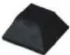
| Power Cord x 1 | SFP+ Dust Cap x 1 | Rubber Feet x 4 | Screws x 8 | |
 |  |  |  | |
If any of these are missing or damaged, please contact your dealer immediately; if possible, retain the carton including the original packing material, and use them again to repack the product in case there is a need to return it to us for repair.
2. Hardware Introduction
2.1 Front Panel
The Front Panel of the Multigigabit Ethernet Switch consists of 8 auto-sensing 10/100/1000/2500Mbps Ethernet RJ45 ports and 1 10GBASE-X SFP+ slot. The LED Indicators are also located on the front panel of the Multigigabit Ethernet Switch.
MGS-910X

MGS-910XP

Figure 1: Front Panel
2.2 LED Indicators
■ System
| LED Color Function | |
| PWR Green Lights to indicate that the Switch has power. |
■ Per 10/100/1000/2500BASE-T Port
| LED Color Function | ||
| 10/100/1000LNK/ACT | Amber | Lights to indicate the link through that port is established successfully at 10/100/1000Mbps.Blinks to indicate that the Switch is actively sending or receiving data over that port. |
| 2500LNK/ACT | Green | Lights to indicate the link through that port is established successfully at 2500Mbps.Blinks to indicate that the Switch is actively sending or receiving data over that port. |
■ 10GBASE-X SFP+ Port
| LED Color Function | ||
| LNK/ACT Green | Lights to indicate the link through that port is established successfully at 10Gbps.Blinks to indicate that the Switch is actively sending or receiving data over that port. | |
■ 802.3at PoE+ TP Interface (MGS-910XP)
| LED Color | Function | |
| 802.3at PoE+ PoE-in-Use | Amber | Lights to indicate that the port is providing PoE in-line power to remote powered device.Off to indicate that the port is not providing PoE in-line power to remote powered device. |
2.3 Multiple Functions of DIP Switch
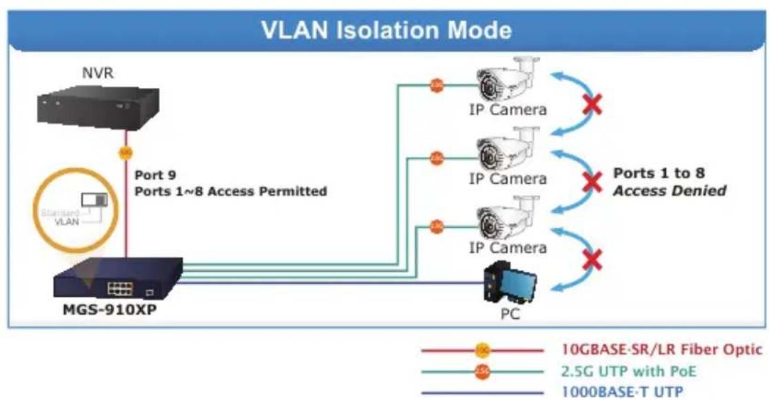
The front panel of the Multigigabit Ethernet Switch provides one DIP switch for Standard or VLAN mode selection. The detailed descriptions are shown in the following table.
| DIP Switch Mode Function | |
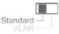 | This mode operate as a general switch and all ports operate at 10/100/1000/2500Mbps auto-negotiation. All ports can communicate with one another. |
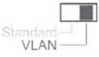 | This mode operate as a VLAN isolation switch and Ports 1 to 8 will isolate respectively. Ports 1 to 8 can only communicate with port 9. |

Note
Please adjust the DIP switch before powering on the Multigigabit Ethernet Switch.
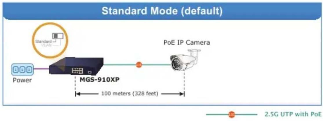
flowchart
graph LR
    A["Power"] --> B["MGS-910XP"]
    B --> C["PoE IP Camera"]
    D["Standard Mode (default)"] --> E["2.5G UTP with PoE"]
    style A fill:#cce5ff,stroke:#333
    style B fill:#e6f7ff,stroke:#333
    style C fill:#ffe6cc,stroke:#333
    style D fill:#fff2cc,stroke:#333
    style E fill:#ffcccc,stroke:#333
flowchart
graph TD
    A["NVR"] -->|Port 9 Ports 1~8 Access Permitted| B["MGS-910XP"]
    B --> C["PC"]
    C --> D["IP Camera"]
    C --> E["IP Camera"]
    C --> F["IP Camera"]
    D --> G["Ports 1 to 8 Access Denied"]
    E --> G
    F --> G
    style A fill:#f9f,stroke:#333
    style B fill:#ccf,stroke:#333
    style C fill:#cfc,stroke:#333
    style D fill:#fcc,stroke:#333
    style E fill:#fcc,stroke:#333
    style F fill:#fcc,stroke:#333
    style G fill:#ffc,stroke:#333
2.4 Switch Rear Panel
Figure 2 shows the rear panel of the MGS-910X/910XP
MGS-910X

MGS-910XP

Figure 2: Rear Panel
■ AC Power Receptacle

Power Note
The device is a power-required device, which means it will not work till it is powered. If your networks should be active all the time, please consider using UPS (uninterrupted power supply) for your device. It will prevent you from network data loss or network downtime.

Power Note
In some areas, installing a surge suppression device may also help to protect your Multigigabit Ethernet Switch from being damaged by unregulated surge or current to the Multigigabit Ethernet Switch or the power adapter.
3. Hardware Installation
This part describes how to install your Multigigabit Ethernet Switch and make connections to it. Please follow the procedure below:

Note
This Multigigabit Ethernet Switch does not need software configuration.
3.1 Rack Mounting
To install the Multigigabit Ethernet Switch on the desktop, simply follow these steps:
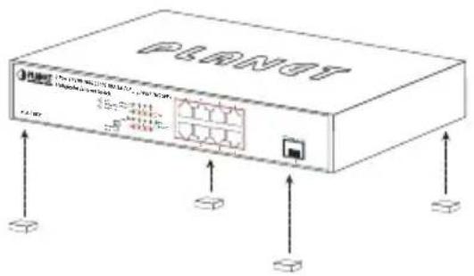
Step 1: Attach the rubber feet to the recessed areas on the bottom of the Multigigabit Ethernet Switch.
Step 2: Place the Multigigabit Ethernet Switch on the desktop near an AC power source.
Step 3: Keep enough ventilation space between the Multigigabit Ethernet Switch and the surrounding objects.

Note
When choosing a location, please keep in mind the environmental restrictions discussed in Section 3 under Product Specifications.
Step 4: Connect your Multigigabit Ethernet Switch to network devices.
A. Connect one end of a standard network cable to the 10/100/1000/2500BASE-T RJ45 ports on the front of the Multigigabit Ethernet Switch.
B. Connect the other end of the cable to the network devices such as printer servers, workstations or routers, etc.
Step 5: Supply power to the Multigigabit Ethernet Switch.
A. Connect one end of the power cable to the Multigigabit Ethernet Switch.
B. Connect the power plug of the power cable to a standard wall outlet.
When the Multigigabit Ethernet Switch receives power, the Power LED should remain solid Green.
3.2 Rack Mounting
To install the Multigigabit Ethernet Switch in a 19-inch standard rack, follow the instructions described below:
Step 1: Place your Multigigabit Ethernet Switch on a hard flat surfac the front panel positioned towards your front side.
Step 2: Attach a rack-mount bracket to each side of the Switch with supplied screws attached to the package. Figure 3 shows how to attach brackets to one side of the Multigigabit Ethernet Switch.
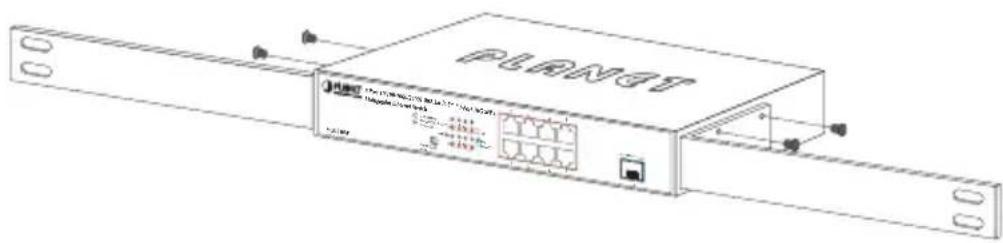
Figure 3: Attaching the brackets to the Multigigabit Ethernet Switch
Caution:
You must use the screws supplied with the mounting brackets. Damage caused to the parts by using incorrect screws would invalidate your warranty.
Step 3: Secure the brackets tightly.
Step 4: Follow the same steps to attach the second bracket to the opposite side.
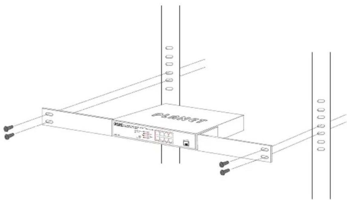
Step 5: After the brackets are attached to the Multigigabit Ethernet Switch, use suitable screws to securely attach the brackets to the rack, as shown in Figure 4.
natural_image
Technical line drawing of a network device with ports and connectors (no text or symbols)Figure 4: Mounting the Multigigabit Ethernet Switch in a Rack
Step 6: Proceed with Steps 4 and 5 of Desktop Installation to connect the network cabling and supply power to your Multigigabit Ethernet Switch.
3.3 Installing the SFP+ Transceiver
The sections describe how to insert an SFP+ transceiver into an SFP+ slot.
The SFP+ transceivers are hot-pluggable and hot-swappable. You can plug in and out the transceiver to/from any SFP+ port without having to power down the Multigigabit Ethernet Switch, as Figure 5 shows.
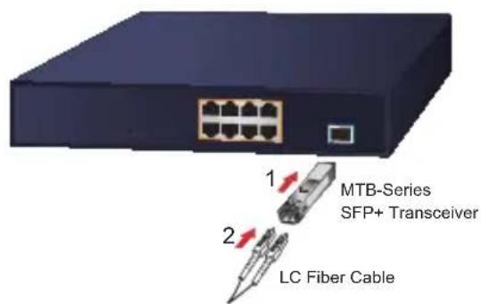
Figure 5: Plugging In the SFP+ Transceiver

Note
It is recommended to use PLANET SFP+ on the Multigigabit Ethernet Switch. If you insert an SFP+ transceiver that is not supported, the Multigigabit Ethernet Switch will not recognize it.
■ 10GBASE-X SR/LR:
Before connecting the other switches, workstation or media converter, please do the following:
-
Make sure both sides of the SFP+ transceiver are with the same media type; for example, 10GBASE-SR to 10GBASE-SR, 10GBASE-LR to 10GBASE-LR.
-
Check whether the fiber-optic cable type matches the SFP+ transcei model.
To connect to 10GBASE-SR SFP+ transceiver, use the multi-mode cable with one side being the male duplex LC connector type.
To connect to 10GBASE-LR SFP+ transceiver, use the single-mod-cable with one side being the male duplex LC connector type.
■ Connecting the fiber cable
-
Attach the duplex LC connector on the network cable to the SFP+ transceiver.
-
Connect the other end of the cable to a device like a switch with SFP+ installed, workstation with fiber NIC or media converter.
■ Removing the Transceiver Module
-
Make sure there is no network activity by consulting or checking with the network administrator. Or through the management interface of the switch/converter (if available) to disable the port in advance.
-
Remove the Fiber Optic Cable gently.
-
Turn the lever of the MTB module to a horizontal position.
-
Pull out the module gently through the lever.
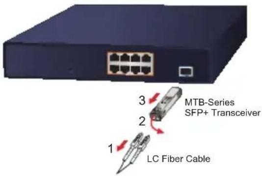
Figure 6: Pulling Out from the Transceiver

Never pull out the module without pulling the lever or the push bolts on the module. Directly pulling out the module with effort could damage the module and SFP+ module slot of the Multi-gigabit Ethernet Switch.
■ 2.5G/1G/100/10BASE-T
The 2.5G/1G/100/10BASE-T port comes with auto-negotiation capability. It automatically supports 10BASE-T, 100BASE-TX, 1GBASE-T and 2.5GBASE-T networks. Users only need to plug a working network device into the 2.5G/1G/100/10BASE-T port, and then turn on the Multigigabit Ethernet Switch. The port will automatically run at 10Mbps, 100Mbps, 1000Mbps and 2500Mbps after the negotiation with the connected device.
■ Connecting the UTP Cable
The 2.5G/1G/100/10BASE-T port uses RJ45 socket -- similar to phone jack -- for connection of unshielded twisted-pair cable (UTP).
The 802.3/802.3u/802.3ab/802.3bz/802.3ae Ethernet standard requires Category 5 UTP for 10/100Mbps while 10BASE-T/100BASE-TX. 2.5G/1G/100/10BASE-T uses Cat5e/6/6A/7 UTP (see table below). Maximum distance is 100 meters (328 feet).
| Standard | Transfer Speed | Cable Requirements (100m) |
| 2.5GBASE-T | 2500Mbit/s Cat. | 5e/Cat. 6/Cat. 6A/Cat. 7 |
| 1GBASE-T | 1000Mbit/s Cat. | 5e/Cat. 6/Cat. 6A/Cat. 7 |
| 100BASE-TX | 100Mbit/s Cat. | 5/Cat. 5e/Cat. 6/Cat. 6A/Cat. 7 |
| 10BASE-T | 10Mbit/s | Cat. 3/Cat. 4/Cat. 5/Cat. 5e/Cat. 6/Cat. 6A/Cat. 7 |
4. Product Specifications
| Product MGS-910X MGS-910XP | ||
| Hardware Specifications | ||
| 10/100/1000/2500BASE-T Copper Interfaces | 8 | 8 |
| 10GBASE-X SFP+ interface | 1 | 1 |
| DIP Switch | Selectable operation mode■ Standard■ VLAN | Selectable operation mode■ Standard■ VLAN |
| LED | System■ Power (Green)10/100/1000/2500T RJ45 Interfaces■ 10/100/1000 LNK/ACT (Amber)■ 2500 LNK/ACT (Green)10G SFP+ Interface■ LNK/ACT (Green) | System■ Power (Green)10/100/1000/2500T RJ45 Interfaces■ 10/100/1000 LNK/ACT (Amber)■ 2500 LNK/ACT (Green)■ PoE-in-Use (Amber)10G SFP+ Interface■ LNK/ACT (Green) |
| Weight 1505g 1739g | ||
| Power Requirements | 100~240V AC, 1A, 50-60Hz | 100~240V AC, 3A, 50-60Hz |
| Power Consumption/Dissipation | 6.6 watts/22.5 BTU 140 watts/447.6BTU | |
| Thermal Fan 1 | ||
| Dimensions (W x D x H) | 280 x 180 x 44mm 280 x 180 x 44mm | |
| ESD Protection | Contact discharge of ±6KV DC,Air discharge of ±8KVDC | Contact discharge of ±6KV DC,Air discharge of ±8KVDC |
| Surge Protection ±6KV ±6KV | ||
| Switching | ||
| Switch Architecture Store-and-Forward Store-and-Forward | ||
| Switch Fabric 60Gbps 60Gbps | ||
| Switch Throughput@64bytes | 44.64Mpps 44.64Mpps | |
| MAC Address Table 4K entries 4K entries | ||
| Jumbo Frame 12K 12K | ||
| Flow Control | IEEE 802.3x pause frame for full duplex; back pressure for half duplex | IEEE 802.3x pause frame for full duplex; back pressure for half duplex |
| Power over Ethernet | ||
| PoE Standard | IEEE 802.3at Power over Ethernet Plus/PSE | |
| PoE Injector Ports 8 | ||
| PoE Power Supply Type | End-span: 1/2 (+), 3/6 (-) | |
| PoE Power Output | Per port 54 DC, 300mA. max. 15.4 watts (IEEE 802.3af) Per port 54V DC, 600mA. max. 32 watts (IEEE 802.3at) | |
| PoE Power Budget 120 watts | ||
| Number of PDs, 7 watts 8 | ||
| Number of PDs, 15.4 watts | 7 | |
| Number of PDs, 30 watts 4 | ||
| Standards Conformance | ||
| Regulatory Compliance FCC | Part 15 Class A, CE FCC | Part 15 Class A, CE |
| Standards Compliance | IEEE 802.3 (Ethernet)IEEE 802.3u(Fast Ethernet)IEEE 802.3ab(Gigabit Ethernet)IEEE 802.3bz(2.5Gigabit Ethernet)IEEE 802.3ae 10Gbps EthernetIEEE 802.3x (Full-Duplex Flow Control)IEEE 802.3az Energy Efficient Ethernet (EEE) | IEEE 802.3 (Ethernet)IEEE 802.3u(Fast Ethernet)IEEE 802.3ab(Gigabit Ethernet)IEEE 802.3bz(2.5Gigabit Ethernet)IEEE 802.3ae 10Gbps EthernetIEEE 802.3x (Full-Duplex Flow Control)IEEE 802.3af Power over EthernetIEEE 802.3at Power over Ethernet PlusIEEE 802.3az Energy Efficient Ethernet (EEE) |
| Environment | ||
| Temperature | Operating:0~50 degrees CStorage:-10~70 degrees C | Operating:0~50 degrees CStorage:-10~70 degrees C |
| Humidity(non-condensing) | Operating: 5% to 95%Storage: 5% to 95% | Operating: 5% to 95%Storage: 5% to 95% |
5. Physical Dimensions
The MGS-910X dimensions (W x D x H): 280 x 180 x 44mm
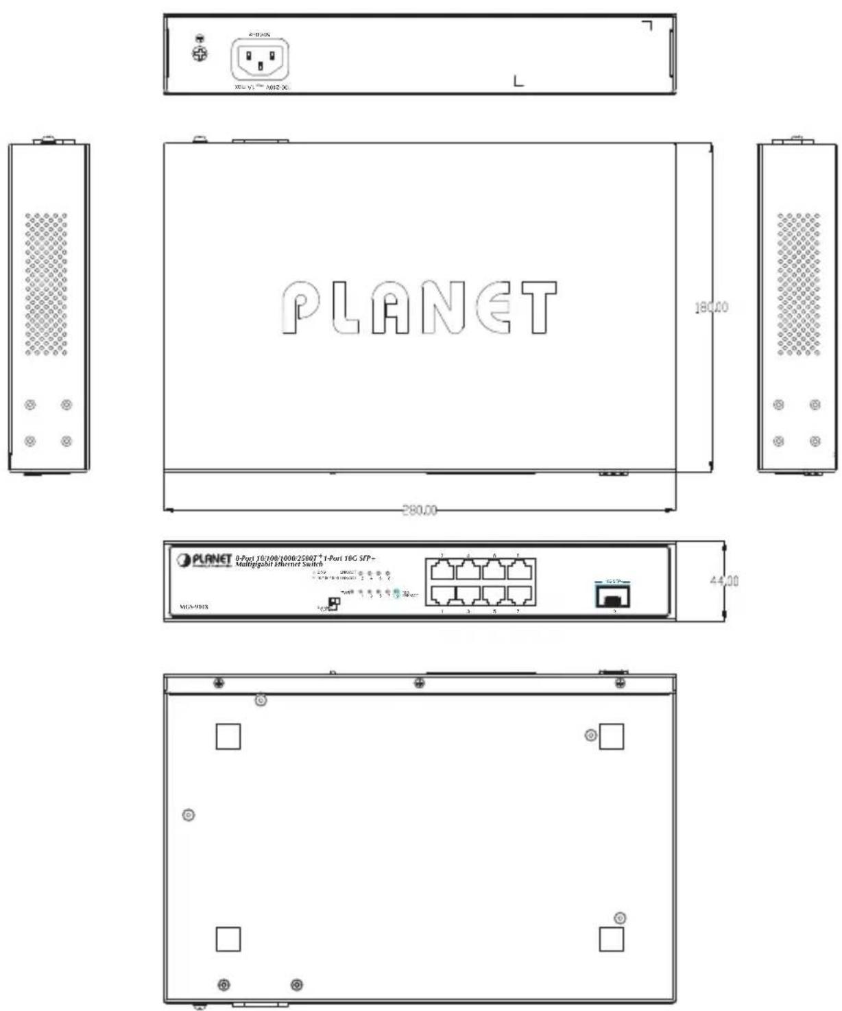
Unit: mm
The MGS-910XP dimensions (W x D x H): 280 x 180 x 44mm
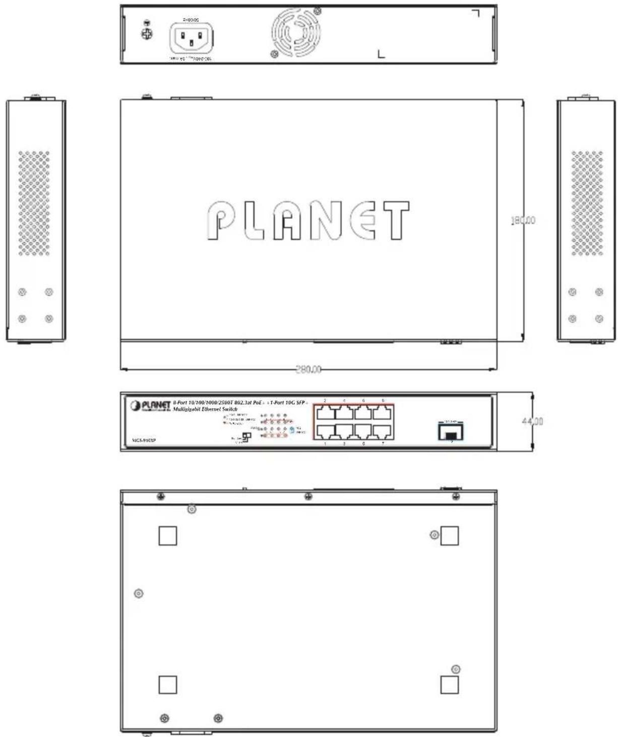
Unit: mm
Customer Support
Thank you for purchasing PLANET products. You can browse our online FAQ resource on PLANET Web site first to check if it could solve your need more support information, please contact PLANET support team.
PLANET online FAQs:
https://www.planet.com.tw/en/support/faq
Support team mail address:
- Table of Contents
- Package Contents
- Hardware Introduction
- Front Panel
- LED Indicators
- Multiple Functions of DIP Switch
- Switch Rear Panel
- ■ AC Power Receptacle
- Hardware Installation
- Rack Mounting
- Rack Mounting
- Caution:
- Installing the SFP+ Transceiver
- ■ 10GBASE-X SR/LR:
- ■ Connecting the fiber cable
- ■ Removing the Transceiver Module
- ■ 2.5G/1G/100/10BASE-T
- ■ Connecting the UTP Cable
- Product Specifications
- Physical Dimensions
- Customer Support
Brand : Planet
Model : MGS-910XP
Category : Switch