FGSD-2621P - Switch Planet - Free user manual and instructions
Find the device manual for free FGSD-2621P Planet in PDF.


| Product Type | 8-Port 10/100TX 802.3at PoE + 1-Port Gigabit TP + 1-Port Gigabit SFP Desktop Switch |
| Model | FGSD-1011HP |
| Dimensions (W x D x H) | 220 x 150 x 44 mm (9 x 5.9 x 1.73 inches) |
| Weight | 1223 g (2.7 lbs) |
| Power Supply | AC 100-240V, 2.5A, 50-60Hz |
| Power Consumption | 122 watts (416.2 BTU/hr) |
| PoE Standard | IEEE 802.3af/at PoE+, End-span, 8 ports, 120W total budget |
| PoE Power per Port | Up to 30W (IEEE 802.3at) or 15.4W (IEEE 802.3af), 54V DC |
| Ports | 8x 10/100BASE-TX (PoE), 1x 10/100/1000BASE-T, 1x 100/1000BASE-X SFP |
| Switching Capacity | 5.6 Gbps |
| MAC Address Table | 8K entries, auto-learning |
| DIP Switch Modes | Standard (100m), VLAN isolation, Extend (250m at 10Mbps with 30W PoE) |
| LED Indicators | Power, LNK/ACT per port, PoE in Use (amber) on ports 1-8 |
| Mounting | Desktop, rack-mount (brackets included), wall-mount |
| Cooling | Fanless design |
| Operating Environment | 0°C to 50°C, 5-95% humidity (non-condensing) |
| Standards Compliance | IEEE 802.3, 802.3u, 802.3ab, 802.3z, 802.3x, 802.3af/at; FCC Class A, CE |
| Maintenance | Clean with a dry cloth; do not use liquids or aerosols |
| Safety Warnings | Use supplied power cord; ensure proper ventilation; avoid stacking |
| Spare Parts & Repairability | Power cord, rack-mount brackets, rubber feet; no user-serviceable parts inside |
Frequently Asked Questions - FGSD-2621P Planet
User questions about FGSD-2621P Planet
0 question about this device. Answer the ones you know or ask your own.
Ask a new question about this device
Download the instructions for your Switch in PDF format for free! Find your manual FGSD-2621P - Planet and take your electronic device back in hand. On this page are published all the documents necessary for the use of your device. FGSD-2621P by Planet.
USER MANUAL FGSD-2621P Planet
8-Port 10/100TX 802.3at PoE +
1-Port Gigabit TP + 1-Port Gigabit SFP
Desktop Switch
FGSD-1011HP
User's Manual
Copyright
Copyright © 2022 by PLANET Technology Corp. All rights reserved. No part of this publication may be re-produced, transmitted, transcribed, stored in a retrieval system, or translated into any language or computer language, in any form or by any means, electronic, mechanical, magnetic, optical, chemical, manual or otherwise, without the prior written permission of PLANET.
PLANET makes no representations or warranties, either expressed or implied, with respect to the contents hereof and specifically disclaims any warranties, merchantability or fitness for any particular purpose. Any software described in this manual is sold or licensed "as is". Should the programs prove defective following their purchase, the buyer (and not PLANET, its distributor, or its dealer) assumes the entire cost of all necessary servicing, repair, and any incidental or consequential damages resulting from any defect in the software. Further, PLANET reserves the right to revise this publication and to make changes from time to time in the contents hereof without obligation to notify any person of such revision or changes.
All brand and product names mentioned in this manual are trademarks and/or registered trademarks of their respective holders.
Trademarks
PLANET is a registered trademark of PLANET Technology Corp.
All other trademarks belong to their respective owners.
Disclaimer
PLANET Technology does not warrant that the hardware will work properly in all environments and applications, and makes no warranty and representation, either implied or expressed, with respect to the quality, performance, merchantability, or fitness for a particular purpose.
PLANET has made every effort to ensure that this User's Manual is accurate; PLANET disclaims liability for any inaccuracies or omissions that may have occurred. Information in this User's Manual is subject to change without notice and does not represent a commitment on the part of PLANET. PLANET assumes no responsibility for any inaccuracies that may be contained in this User's Manual. PLANET makes no commitment to update or keep current the information in this User's Manual, and reserves the right to make improvements to this User's Manual and/or to the products described in this User's Manual, at any time without notice. If you find information in this manual that is incorrect, misleading, or incomplete, we would appreciate your comments and suggestions.
FCC Warning
This equipment has been tested and found to comply with the limits for a Class A digital device, pursuant to Part 15 of the FCC Rules. These limits are designed to provide reasonable protection against harmful interference when the equipment is operated in a commercial environment. This equipment generates, uses, and can radiate radio frequency energy and, if not installed and used in accordance with the Instruction manual, may cause harmful interference to radio communications. Operation of this equipment in a residential area is likely to cause harmful interference in which case the user will be required to correct the interference at his own expense.
CE Mark Warning
This is a Class A product. In a domestic environment, this product may cause radio interference, in which case the user may be required to take adequate measures.
WEEE Warning
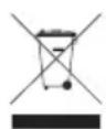
To avoid the potential effects on the environment and human health as a result of the presence of hazardous substances in electrical and electronic equipment, end users of electrical and electronic equipment should understand the meaning of the crossed-out wheeled bin symbol. Do not dispose of WEEE as unsorted municipal waste and have to collect such WEEE separately.
Revision
PLANET 8-Port 10/100TX 802.3at PoE + 1-Port 10/100/1000T + 1-Port 100/1000X SFP Desktop Switch User's Manual
For Model: FGSD-1011HP
Revision: 2.0 (April 2022)
Part No.: EM-FGSD-1011HP_v2.0
Table Of Contents
1. Introduction .... 5
1.1 Checklist.... 5
1.2 Product Description.... 5
1.3 Features 6
1.4 Specifications....7
2. Hardware Description....9
2.1 Front Panel 9
2.1.1 LED Indicators 11
2.2 Rear Panel....12
3. Hardware Installation....13
3.1 Desktop Installation....14
3.2 Rack Mounting 15
3.3 Wall Mounting Installation 16
4. Troubleshooting ....18
Appendix A - 10/100Mbps, 10/100BASE-TX ......19
1. Introduction
1.1 Checklist
Check the contents of your package for the following parts:
FGSD-1011HP x 1 User's Manual x 1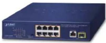 |  |
Power Cord x 1 Rubber Feet x 4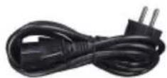 |  |
Rack-mounting Brackets x 2 Screws x 8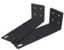 |  |
If any of these pieces are missing or damaged, please contact your dealer immediately; if possible, retain the carton including the original packing material, and use them again to repack the product in case there is a need to return it to us for repair.
1.2 Product Description
The FGSD-1011HP, a new member in the PLANET 802.3at PoE Fast Ethernet Switch family, provides 8-port 10/100Mbps 802.3af/at Power over Ethernet, 1 Gigabit port and 1 Gigabit SFP port with a total of 120 watts of PoE budget. Its PoE power is more than enough for those network applications with Fast Ethernet
speed transmission. The eight 802.3af/at PoE ports feature PoE power injector function which is able to drive 8 IEEE 802.3at compliant powered devices. The FGSD-1011HP also offers a simple, cost-effective and non-blocking wire-speed performance. It comes with a 9-inch metal compact housing, suitable for desktop deployment in SOHO office or department network application.
The mini-GBIC slot built in the FGSD-1011HP supports SFP auto-detection and dual speed as it features 100BASE-FX and 1000BASE-SX/LX SFP (Small Form-factor Pluggable) fiber-optic modules, meaning the administrator now can flexibly choose the suitable SFP transceiver according to the transmission distance or the transmission speed required to extend the network efficiently.
1.3 Features
▶ Physical Port
● 8 10/100Mbps Fast Ethernet ports
● 1 10/100/1000BASE-T Gigabit Ethernet port
● 1 100/1000BASE-X mini-GBIC SFP interface
Power over Ethernet
● Complies with IEEE 802.3af/at Power over Ethernet end-span
● Up to 8 IEEE 802.3af/at devices powered
● Supports PoE Power up to 30 watts for each PoE port
● 120-watt PoE budget
● 8 ports supporting 54V DC power to PoE powered device (Port 1 to port 8)
- Hardware DIP switch for "Standard", "VLAN" and "Extend" mode selection; the "Extend" mode features 30-watt PoE transmit distance of 250m at speed of 10Mbps and VLAN isolation
● Auto detects powered device (PD)
● Circuit protection prevents power interference between ports
● Remote power feeding up to 100m in standard mode
Switching
● Hardware-based 10/100/1000Mbps auto-negotiation and auto MDI/MDI-X
- Flow control for full duplex operation and back pressure for half duplex operation
● Integrates address look-up engine, supporting 8K absolute MAC addresses
● Automatic address learning and address aging
- Solid DIP switch to isolate ports to prevent broadcast storm and defend DHCP spoofing
Hardware
● 9-inch desktop size, 1U height, mountable
● LED indicators for PoE ready/activity and LINK/ACT
- Fanless design
- Internal AC power supply
● Supports Energy-Efficient Ethernet (EEE) function (IEEE 802.3az)
1.4 Specifications
| Model FGSD-1011HP | |
| Hardware Specifications | |
| 10/100Mbps Ports 8 10/100B | BASE-TX MDI/MDI-X RJ45 ports |
| Gigabit Ports 1 10/100/1000 | BASE-T MDI/MDI-X RJ45 port |
| SFP Slot 1 100/1000BASE-X | SFP/mini-GBIC interface |
| PoE Inject Port | 8-port with 802.3af/at PoE injector function (Port-1 to Port-8) |
| LED Display | System:■ Power (Green)10/100BASE-TX RJ45 Interface:■ PoE (Orange, Port-1 to Port-8)■ LNK/ACT (Green, Port-1 to Port-8)10/100/1000BASE-T RJ45 Interface:■ LNK/ACT (Green, Port 9)100/1000BASE-X SFP Interface:■ LNK/ACT (Green, Port 10) |
| DIP Switch | 100m distance in standard mode250m distance in extend mode (based on the cable category) |
| Switch Architecture Store and Forward switch architecture | |
| MAC Address Table 8K MAC address table with auto learning function | |
| Switch Fabric 5.6Gbps | |
| Switch Throughput 4.16Mpps @64bytes | |
| Maximum Packet Size | 9K bytes |
| Flow Control | Back pressure for half duplex; IEEE 802.3x pause frame for full duplex |
| Power Requirements | AC 100~240V, 2.5A max. |
| Power Consumption | 122 watts, 416.2 BTU |
| Dimensions (W x D x H) 220 | x 150 x 44 mm |
| Weight 1223 g | |
| ESD Protection | Contact discharge of ±6KV DCAir discharge of ±8KV DC |
| Surge Immunity ±4KV | |
| Power over Ethernet | |
| PoE Standard | IEEE 802.3af Power over Ethernet/PSEIEEE 802.3at Power over Ethernet Plus/PSE |
| PoE Power Supply Type End | span |
| Power Pin Assignment 1/2 (+), 3/6 (-) | |
| PoE Power Output | Per Port 54V DC, 600mA. max. 30 watts(IEEE 802.3at)Per Port 54V DC, 300mA. max. 15.4 watts(IEEE 802.3af) |
| PoE Power Budget 120 watts | |
| Number of PDs, 7 watts 8 | |
| Number of PDs, 15.4 watts 8 | |
| Number of PDs, 30 watts 4 | |
| Standard Conformance | |
| EMI Safety CE, FCC | |
| Standard Compliance | IEEE 802.3 EthernetIEEE 802.3u Fast EthernetIEEE 802.3ab Gigabit 1000BASE-TIEEE 802.3z Gigabit SX/LXIEEE 802.3x Flow ControlIEEE 802.3af Power over EthernetIEEE 802.3at Power over Ethernet Plus |
| Environment | |
| Operating Environment 0 ~ | 50 degrees C |
| Storage Environment -10 ~ | 70 degrees C |
| Operating Humidity 5 ~ 95% | relative humidity, non-condensing |
| Storage Humidity | 5 ~ 95%, relative humidity, non-condensing |
2. Hardware Description
The switch provides three different running speeds - 10/100/1000Mbps, and automatically distinguishes the speed of the incoming connection.
This section describes the hardware features of the FGSD-1011HP. For easier management and control of the FGSD-1011HP, familiarize yourself with its display indicators and ports. Front panel illustrations in this chapter display the unit LED indicators. Before connecting any network device to the FGSD-1011HP, please read this chapter carefully.
2.1 Front Panel
The Front Panel of the FGSD-1011HP PoE+ Ethernet Switch consists of 8 Auto-Sensing 10/100Mbps Ethernet RJ45 Ports, 1 Auto-Sensing 10/100/1000Mbps Ethernet RJ45 Port and 1 Auto-Sensing 100/1000 Mbps SFP port. The LED Indicators are also located on the front panel of the FGSD-1011HP.

Figure 2-1: FGSD-1011HP Switch Front Panel
The front panel of FGSD-1011HP provides one DIP switch for Standard, VLAN and Extend mode selections. The detailed descriptions are shown in the following table.
| DIP Switch Mode | Function |
Standard 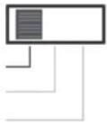 VLAN Extend VLAN Extend | |
Standard 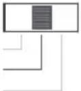 VLAN Extend VLAN Extend |
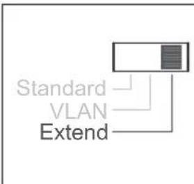
flowchart
graph TD
    A["Standard"] --> B["VLAN"]
    B --> C["Extend"]
This mode makes the FGSD-1011HP operate as a VLAN isolation switch and
- Port 1 to port 8 will isolate respectively.
- Port 1 to port 8 can only communicate with port 9 and port 10 (uplink port).
- 30-watt PoE transmit distance of 250m at speed of 10Mbps.

Please reboot the FGSD-1011HP after adjusting the DIP switch.
Standard Mode (default)
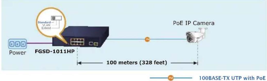
flowchart
graph LR
    A["Power"] --> B["FGSD-1011HP"]
    B --> C["PoE IP Camera"]
    D["Standard VLAN Extend"] --> B
    E["100BASE-TX UTP with PoE"] --> C
    B --> F["100 meters (328 feet)"]
VLAN Isolation Mode
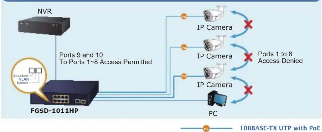
flowchart
graph TD
    A["NVR"] -->|Ports 9 and 10 To Ports 1~8 Access Permitted| B["FGSD-1011HP"]
    B --> C["PC"]
    C --> D["IP Camera"]
    C --> E["IP Camera"]
    C --> F["IP Camera"]
    D --> G["Ports 1 to 8 Access Denied"]
    E --> G
    F --> G
    style A fill:#f9f,stroke:#333
    style B fill:#ccf,stroke:#333
    style C fill:#cfc,stroke:#333
    style D fill:#fcc,stroke:#333
    style E fill:#fcc,stroke:#333
    style F fill:#fcc,stroke:#333
    style G fill:#cff,stroke:#333
Extend Mode
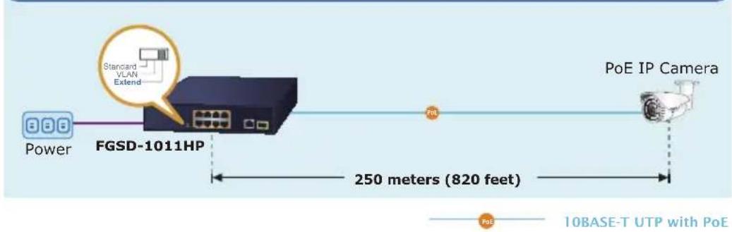
2.1.1 LED Indicators
System
| LED Color Function | ||
| PWR | Green | Lights to indicate that the Switch has power. |
■ Per 10/100BASE-TX Port
| LED Color Function | ||
| 10/100LNK/ACT | Green | Lights to indicate the link through that port is successfully established.Blinks to indicate that the Switch is actively sending or receiving data over that port. |
| PoE in Use Amber | Lights to indicate the port is providing PoE DC in-line power. | |
■ 10/100/1000BASE-T Port
| LED Color | Function | |
| 10/100/1000LNK/ACT | Green | Lights to indicate the link through that port is successfully established.Blinks to indicate that the Switch is actively sending or receiving data over that port. |
■ 100/1000BASE-X SFP Port
| LED Color Function | ||
| 10/100LNK/ACT | Green | Lights to indicate the link through that port is successfully established.Blinks to indicate that the Switch is actively sending or receiving data over that port. |
2.2 Rear Panel
The rear panel of the FGSD-1011HP has an AC inlet power socket, which accepts input power of 100 to 240V AC, 50-60Hz.
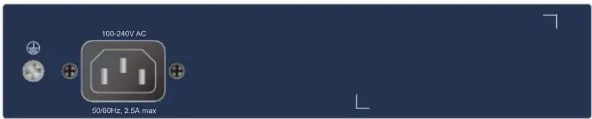
Figure 2-2: FGSD-1011HP Switch Rear Panel

- The device is a power-required device which means it will not work till it is powered. If your networks should be active all the time, please consider using UPS (Uninterrupted Power Supply) for your device. It will prevent you from network data loss or network downtime.
- In some areas, installing a surge suppression device may also help to protect your FGSD-1011HP from being damaged by unregulated surge or current to the FGSD-1011HP.
3. Hardware Installation
Start up
Please refer to the following for your cabling:
■ 10/100BASE-TX
All 10/100BASE-TX ports come with Auto-Negotiation capability. They automatically support 100BASE-TX and 10BASE-T networks. Users only need to plug a working network device into one of the 10/100 BASE-TX ports, and then turn on the FGSD-1011HP. The port will automatically run at 10Mbps, 20Mbps, 100Mbps or 200Mbps after negotiating with the connected device.
■ 10/100/1000BASE-T
The 10/100/1000BASE-T port comes with Auto-Negotiation capability, which automatically supports 1000BASE-T, 100BASE-TX and 10BASE-T networks. Users only need to plug a working network device into the 10/100/1000BASE-T port, and then turn on the PoE Ethernet Switch. The port will automatically run at 10Mbps, 20Mbps, 100Mbps or 200Mbps and 1000Mbps or 2000Mbps after negotiating with the connected device.
Cabling
Both 10/100BASE-TX and 10/100/1000BASE-T ports use RJ45 sockets -- similar to the phone jacks -- for connection of unshielded twisted-pair cable (UTP). The IEEE 802.3/802.3u/802.3ab Fast/Gigabit Ethernet standard requires Category 5 UTP for 100Mbps 100BASE-TX. 10BASE-T networks can use Cat.3, 4, 5 or 1000BASE-T uses 5/5e/6 UTP (see table below). Maximum distance is 100 meters (328 feet).
| Port Type Cable | Type Connector | |
| 10BASE-T Cat.3, 4, 5, | 2-pair RJ45 | |
| 100BASE-TX Cat.5, 5e | UTP, 4-pair RJ45 | |
| 1000BASE-T | Cat.5/5e/6 UTP, 4-pair | RJ45 |
Any Ethernet devices like hubs/PCs can be connected to the FGSD-1011HP by using straight-through wires. The whole 10/100/1000 Mbps ports are auto-MDI/MDI-X that can be used on straight-through or crossover cable.
3.1 Desktop Installation
To install the FGSD-1011HP on desktop, simply follow the following steps:
Step 1: Attach the rubber feet to the recessed areas on the bottom of the FGSD-1011HP, as shown in Figure 3-1.
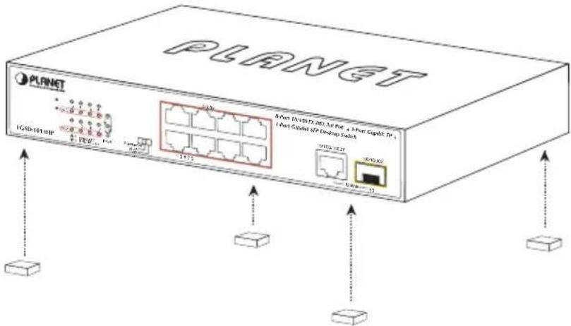
Figure 3-1: Attaching the Rubber Feet to the FGSD-1011HP
Step 2: Place the FGSD-1011HP on desktop near an AC power source.
Step 3: Keep enough ventilation space between the FGSD-1011HP and the surrounding objects.

When choosing a location, please keep in mind the environmental restrictions discussed in Chapter 1, Section 4, under Specifications.
Step 4: Connect your FGSD-1011HP to 802.3af/802.3at complied power devices (PDs) and other network devices.
A. Connect one end of a standard network cable to the 10/100BASE-TX RJ45 ports on the front panel of the FGSD-1011HP.
B. Connect the other end of the cable to the network devices such as printer servers, workstations, routers, etc.

Connection to the Switch requires UTP Category 5, 5e, 6 network cabling with RJ45 tips.
Note
Step 5: Supply power to the FGSD-1011HP.
A. Connect one end of the power cable to the FGSD-1011HP.
B. Connect the power plug of the power cable to a standard wall outlet.
When the FGSD-1011HP receives power, the Power LED should remain solid Green.
3.2 Rack Mounting
To install the FGSD-1011HP in a 19-inch standard rack, follow the instructions described below.
Step 1: Place your FGSD-1011HP on a hard flat surface, with the front panel positioned towards your front side.
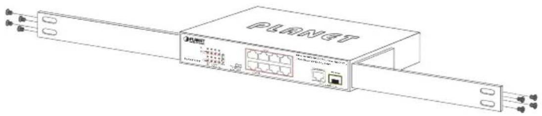
Step 2: Attach a rack-mount bracket to each side of the FGSD-1011HP with supplied screws attached to the package. Figure 3-2 shows how to attach brackets to one side of the FGSD-1011HP.
natural_image
Line drawing of a Planet network switch device with ports and connectors (no text or symbols)Figure 3-2: Attaching the Brackets to the FGSD-1011HP.

natural_image
Warning symbol: a white triangle with an exclamation mark inside, set against a dark gray background (no text or numbers)You must use the screws supplied with the mounting brackets. Damage caused to the parts by using incorrect screws would invalidate the warranty.
Step 3: Secure the brackets tightly.
Step 4: Follow the same steps to attach the second bracket to the opposite side.
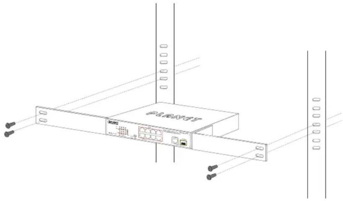
Step 5: After the brackets are attached to the FGSD-1011HP, use suitable screws to securely attach the brackets to the rack, as shown in Figure 3-3.
natural_image
Line drawing of a network device labeled 'PLANT' with ports and cables, no readable text or symbols beyond the labelFigure 3-3: Mounting the FGSD-1011HP in a Rack
Step 6: Proceed with Steps 4 and 5 of session 3.1 Desktop Installation to connect the network cabling and supply power to your Switch.
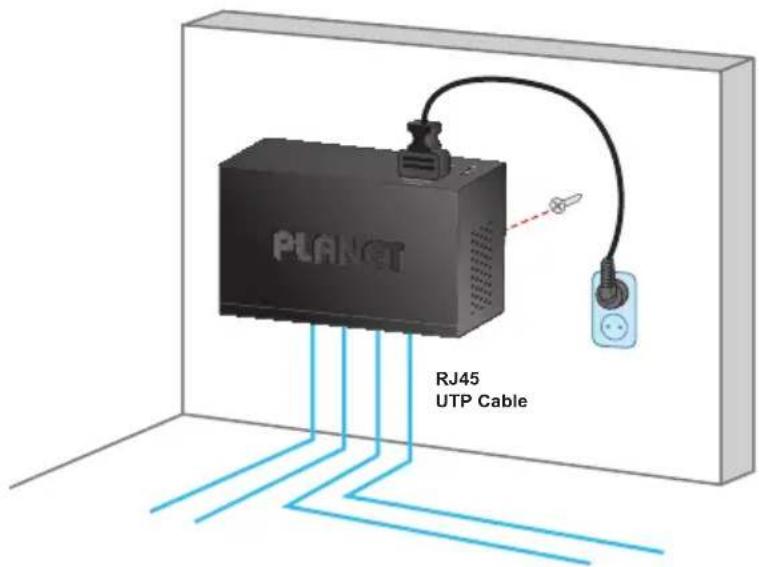
3.3 Wall Mounting Installation
Step 1: Please find the wall that can mount the FGSD-1011HP.
Step 2: Install two screws on the wall.
Step 3: Hang the FGSD-1011HP on the screws from the wall.
Step 4: Repeat Step 5 of Desktop Installation for power supply to the FGSD-1011HP.

Before mounting the device to the wall, please check the location of the electrical outlet and the length of the Ethernet cable.
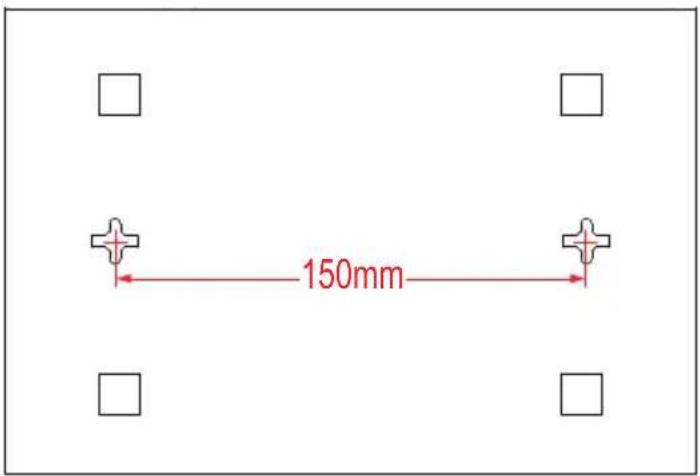
FGSD-1011HP Switch Bottom Side
4. Troubleshooting
This chapter contains information to help you solve issues. If the FGSD-1011HP is not functioning properly, make sure the FGSD-1011HP was set up according to instructions in this manual.
Q1: The Link LED is not lit.
Solution:
Check the cable connection and also try to swap one new cable.
Q2: 100BASE-TX port link LED is lit, but the traffic is irregular.
Solution:
Make sure the attached device is not set to full duplex. Some devices use a physical or software switch to change duplex modes. Auto-negotiation may not recognize this type of full-duplex setting.
Q3: Why the Switch isn't connected to the network.
Solution:
Check the LNK/ACT LED on the FGSD-1011HP. Try another port on the FGSD-1011HP. Make sure the cable is installed properly. Make sure the cable is the right type. Turn off the power. After a while, turn on the power again.
Q4: Why the FGSD-1011HP, connected to PoE device, cannot be powered on.
Solution:
Please check the cable type of the connection from the FGSD-1011HP to the other end. The cable should be an 8-wire UTP, Category 5 or above and EIA568 cable within 100 meters. A cable with only 4-wire, short loop or over 100 meters will affect the power supply.
Please make sure the device is fully complied with IEEE 802.3af/IEEE 802.3at standard.
Q5: What is the power output of each PoE port?
Solution:
- Each PoE port supports 51-52V DC, 600mA and a maximum of 30 watts of power output. Detect and inject by the standard of IEEE 802.3at.
- Each PoE port supports 51-52V DC, 300mA and a maximum of 15.4 watts of power output. Detect and inject by the standard of IEEE 802.3af.
Appendix A - 10/100Mbps, 10/100BASE-TX
When connecting the Switch to another Fast Ethernet switch, a straight-through or crossover cable might be necessary. Each port of the Switch supports auto-MDI/MDI-X detection, meaning you can directly connect the Switch to any Ethernet devices without making a crossover cable. The following table and diagram show the standard RJ45 receptacle/connector and their pin assignments:
| RJ45 Connector Pin Assignment | ||
| Contact | MDIMedia Dependent Interface | MDI-XMedia Dependent Interface-Cross |
| 1 Tx + | (transmit) Rx + (receive) | |
| 2 Tx - | (transmit) Rx - (receive) | |
| 3 Rx + | (receive) Tx + (transmit) | |
| 4, 5 Not used | ||
| 6 Rx - | (receive) Tx - (transmit) | |
| 7, 8 Not used | ||
The standard cable, RJ45 pin assignment
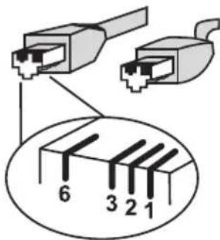
The standard RJ45 receptacle/connector
There are 8 wires on a standard UTP/STP cable and each wire is color-coded. The following shows the pin allocation and color of straight-through cable and crossover cable connection:
Figure A-1: Straight-through and Crossover Cable
Please make sure your connected cables are with the same pin assignment and color as the above description before deploying the cables into your network.
- Copyright
- Trademarks
- Disclaimer
- FCC Warning
- CE Mark Warning
- WEEE Warning
- Revision
- Table Of Contents
- Introduction .... 5
- Hardware Description....9
- Hardware Installation....13
- Troubleshooting ....18
- Introduction
- Checklist
- Product Description
- Features
- ▶ Physical Port
- Power over Ethernet
- Switching
- Hardware
- Hardware Description
- Front Panel
- LED Indicators
- Rear Panel
- Hardware Installation
- Start up
- ■ 10/100BASE-TX
- ■ 10/100/1000BASE-T
- Cabling
- Desktop Installation
- Rack Mounting
- Wall Mounting Installation
- Troubleshooting
- Q1: The Link LED is not lit.
- Solution:
- Q2: 100BASE-TX port link LED is lit, but the traffic is irregular.
- Q3: Why the Switch isn't connected to the network.
- Q4: Why the FGSD-1011HP, connected to PoE device, cannot be powered on.
- Q5: What is the power output of each PoE port?
- Appendix A - 10/100Mbps, 10/100BASE-TX
Brand : Planet
Model : FGSD-2621P
Category : Switch