IVC-234GT - Switch Planet - Free user manual and instructions
Find the device manual for free IVC-234GT Planet in PDF.


| Product Type | Industrial 1-Port BNC/RJ11 to 4-Port Gigabit Ethernet Extender |
| Brand | Planet |
| Model | IVC-234GT |
| Dimensions (W x D x H) | 32 x 135 x 87.8 mm |
| Weight | 185 g |
| Power Input | Dual 12~48V DC, 24V AC |
| Power Consumption | 10W (max) |
| Operating Temperature | -40°C to 75°C |
| Storage Temperature | -40°C to 75°C |
| Operating Humidity | 5% to 95% (non-condensing) |
| Interfaces | 4x 10/100/1000BASE-T RJ45, 1x BNC female, 1x RJ11 |
| VDSL Compliance | ITU-T G.993.1, G.993.2 (Profile 17a/30a), G.997.1, G.993.5, G.INP |
| Maximum Distance | Up to 1200m (3,937 ft) over coaxial or twisted pair |
| DIP Switch Settings | CO/CPE mode, G.INP/Interleave, Asymmetric/Symmetric, SNR 8dB/12dB |
| LED Indicators | P1, P2, Fault, VDSL, CO, CPE, 1000, 10/100 |
| Housing | Metal (IP30) |
| Mounting | DIN-rail and wall-mount |
| Safety Compliance | FCC Part 15 Class A, CE, WEEE |
| Maintenance | Clean with dry cloth; avoid liquids. No user-serviceable parts. |
| Spare Parts and Repairability | Included: power supply, wall-mount kit, dust caps. Professional repair only. |
| General Information | Industrial grade extender suitable for harsh environments. Requires no software configuration. |
Frequently Asked Questions - IVC-234GT Planet
User questions about IVC-234GT Planet
0 question about this device. Answer the ones you know or ask your own.
Ask a new question about this device
Download the instructions for your Switch in PDF format for free! Find your manual IVC-234GT - Planet and take your electronic device back in hand. On this page are published all the documents necessary for the use of your device. IVC-234GT by Planet.
USER MANUAL IVC-234GT Planet
Industrial 1-Port BNC/RJ11 to 4-Port Gigabit Ethernet Extender
IVC-234GT
User's Manual
Trademarks
Copyright © PLANET Technology Corp. 2018.
Contents are subject to revision without prior notice.
PLANET is a registered trademark of PLANET Technology Corp. All other trademarks belong to their respective owners.
Disclaimer
PLANET Technology does not warrant that the hardware will work properly in all environments and applications, and makes no warranty and representation, either implied or expressed, with respect to the quality, performance, merchantability, or fitness for a particular purpose.
PLANET has made every effort to ensure that this User's Manual is accurate; PLANET disclaims liability for any inaccuracies or omissions that may have occurred.
Information in this User's Manual is subject to change without notice and does not represent a commitment on the part of PLANET. PLANET assumes no responsibility for any inaccuracies that may be contained in this User's Manual. PLANET makes no commitment to update or keep current the information in this User's Manual, and reserves the right to make improvements to this User's Manual and/or to the products described in this User's Manual, at any time without notice.
If you find information in this manual that is incorrect, misleading, or incomplete, we would appreciate your comments and suggestions.
FCC Warning
This equipment has been tested and found to comply with the limits for a Class A digital device, pursuant to Part 15 of the FCC Rules. These limits are designed to provide reasonable protection against harmful interference when the equipment is operated in a commercial environment. This equipment generates, uses, and can radiate radio frequency energy and, if not installed and used in accordance with the Instruction manual, may cause harmful interference to radio communications. Operation of this equipment in a residential area
is likely to cause harmful interference in which case the user will be required to correct the interference at his own expense.
CE Mark Warning
This is a Class A product. In a domestic environment, this product may cause radio interference, in which case the user may be required to take adequate measures.
Energy Saving Note of the Device
This power required device does not support Standby mode operation. For energy saving, please remove the power cable to disconnect the device from the power circuit. Without removing power cable, the device will still consume power from the power source. In view of Saving the Energy and reducing the unnecessary power consumption, it is strongly suggested to remove the power connection for the device if this device is not intended to be active.
WEEE Warning

To avoid the potential effects on the environment and human health as a result of the presence of hazardous substances in electrical and electronic equipment, end users of electrical and electronic equipment should understand the meaning of the crossed-out wheeled bin symbol. Do not dispose of WEEE as unsorted municipal waste and have to collect such WEEE separately.
Revision
PLANET Industrial 1-Port BNC/RJ11 to 4-Port Gigabit Ethernet Extender User's Manual
For Models: IVC-234GT
Revision: 1.0 (May 2018)
Part No.: 2350-AC0530-000
Table of Contents
- Package Contents .... 5
- Hardware Introduction.... 6
2.1 Physical Dimensions....6
2.2 Front View....7
2.3 Top View 8
2.4 IVC-234GT LED Indicators 8
2.5 DIP Switch and Link Type....9
- Product Specifications....12
- Applications....14
4.1 Point-to-Point Application -- LAN to LAN Connection .....14
4.2 Point to Multi-point Application (IP surveillance)....16
- Installations....17
5.1 Wiring the Power Inputs ....17
5.2 Wiring the Fault Alarm Contact....18
5.3 DIN-rail Mounting Installation....19
5.4 Wall-mount Plate Mounting....21
- Performance Table....22
- Troubleshooting ....24
- FAQs....25
- Customer Support....26
1. Package Contents
Thank you for purchasing PLANET Industrial 1-Port BNC/RJ11 to 4-Port Gigabit Ethernet Extender, IVC-234GT. In the following sections, the term "Industrial Ethernet Extender" means the IVC-234GT.
Open the box of the Industrial Ethernet Extender and carefully unpack it. The box should contain the following items:
| Industrial Ethernet Extender x 1 User's Manual x 1 | |
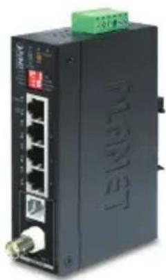 |  |
| RJ11/RJ45 Dust Caps Wall-mount Kit | |
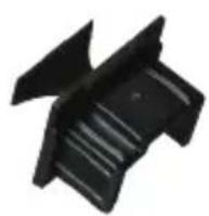 | 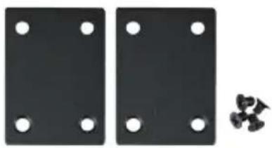 |
If any of these are missing or damaged, please contact your dealer immediately; if possible, retain the carton including the original packing material, and use them again to repack the product in case there is a need to return it to us for repair.
2. Hardware Introduction
2.1 Physical Dimensions
■ Dimensions (W x D x H): 32 x 135 x 87.8mm
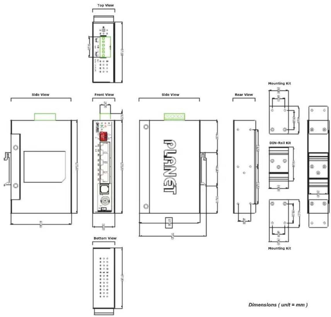
Figure 2-1: IVC-234GT Three-View Diagram
2.2 Front View
Front Panel

Figure 2-2: IVC-234GT Front Panel
The unit's front panel provides the following simple interfaces:
▶ LEDs for Power 1, Power 2 and VDSL2
4 10/100/1000BASE-T RJ45 ports
BNC female/ RJ11 connector via DIP switch
➢ Selectable CO/CPE mode, Target Band Plan and Target SNR Margin via DIP switch
2.3 Top View
The upper panel of the Industrial Ethernet Extender consists of one terminal block connector within two DC power inputs.
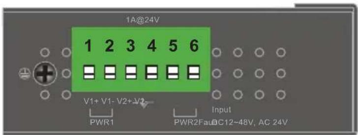
Figure 2-3: IVC-234GT Top View
2.4 IVC-234GT LED Indicators
The rich diagnostic LEDs on the front panel can provide the operating status of individual port and whole system.
System
| LED Color Function | |
| P1 Green Lights | to indicate DC power input 1 has power. |
| P2 Green Lights | to indicate DC power input 2 has power. |
| Fault Red Lights | to indicate that DC power has failed. |
VDSL
| LED Color Function | |||
| VDSL Green | Lit | Indicates that the VDSL connection is established. | |
| Fast Blink | Indicates that the VDSL connection is in training status (about 15 seconds). | ||
| Slow Blink | Indicates that the VDSL connection is in idle status. | ||
| CO | Green Lit | Indicates the Industrial Ethernet Extender is running in CO mode. | |
| CPE | Green Lit | Indicates the Industrial Ethernet Extender is running in CPE mode. | |
■ 100/1000BASE-T Port
| LED Color Function | |||
| 1000 Green | Lit | Indicates that the port is operating at 1000Mbps. | |
| Blink | Indicates that the Industrial Ethernet Extender is actively sending or receiving data over that port at 1000Mbps. | ||
| Off | Indicates that the port is link down or 10/100Mbps. | ||
| 10/100 Green | Lit | Indicates that the port is operating at 100Mbps or 10Mbps. | |
| Blink | Indicates that the Industrial Ethernet Extender is actively sending or receiving data over that port at 100Mbps or 10Mbps. | ||
| Off | Indicates that the port is link down or 1000Mbps. | ||
2.5 DIP Switch and Link Type
Link Type
The BNC mode allows Industrial Ethernet Extender to connect and transfer data by using BNC cable.
The RJ11 mode allows Industrial Ethernet Extender to connect and transfer data by using telephone wire
DIP Switch
The Industrial Ethernet Extender provides a selectable 4-position DIP switch. Switch them on or off to obtain the best coaxial/RJ11 cable connection over a distance.
| DIP | DIP-1 DIP | -2 DIP-3 DIP-4 | ||
| Mode Transmission Band | Profile SNR Margin | |||
| OFF CO G.INP | Asymmetric 1 | 2dB | ||
| ON (default) | CPE Interleave | Symmetric | 8dB | |

Note
By default, the 4-position switches of the DIP switch, set at the "ON" position, are operated as "CPE". For operating as "CO", please turn DIP 1 switch to the "OFF" position. Then adjust other DIP switches accordingly to fulfill different network application demands.
■ DIP-1: Mode (CO / CPE)
| CO (Central Office) | The Master device mode, usually the CO device, is located at the data center of ISP or enterprise to link to the backbone. |
| CPE(Customer Premises Equipment) | The Slave device mode, usually the CPE device, is located at branch office, home or remote side as the long reach data receiver. The CPE can be connected to the PC, IP camera or wireless access point, or other network devices. |

Note
When the Industrial Ethernet Extender operates in CPE mode, DIP switches 2, 3, and 4 are without function.
■ DIP-2: Transmission (G. INP and Interleave mode)
| G. INP | Method of protection against bursts from other devices or lines to impact your xDSL connection. |
| Interleave | Method of error correction used on xDSL connection.Interleave requires additional latency to improve resilience to burst of error. |
■ DIP-3: Band Profile (Asymmetric/Symmetric)
| Asymmetric | The asymmetric mode provides more bandwidth than the other side. This mode provides the highest bandwidth in short range. |
| Symmetric | With the G.997 band plan supported, the symmetric mode can provide almost the same rate of downstream and upstream. |
■ DIP-4: SNR (Signal Noise Ratio) Margin
When the SNR margin is selected, the system provides 12dB/8dB SNR margin for all usable loop lengths. Better channel noise protection is made with the higher SNR margin.

Please power off the Industrial Ethernet Extender before making any transmission mode adjustment.
3. Product Specifications
| Product IVC-234GT | |||
| Hardware Specifications | |||
| TP interface 4 | 10/100/1000BASE-T RJ45 auto-MDI/MDI-X ports | ||
| VDSL | BNC | 1 BNC female Ethernet over Coaxial | |
| Cabling | Coaxial cable: 75 ohmRG-6/U cable, less than 12 /1000 ftRG-59/U cable, less than 30 /1000 ft. | ||
| Maximum Distance | Max. 1200m with data transmission(3,937ft.) | ||
| RJ11 | 1 VDSL2 RJ11 female phone jack Twisted-pair telephone wires (AWG-24 or better) up to 1.2km(3,937ft.) | ||
| Functionality | DIP-1 Select CO or CPE mode | ||
| DIP-2 Select G.INP or Interleaved mode | |||
| DIP-3 | Select Band Profile (Asymmetric or Symmetric) | ||
| DIP-4 Select SNR of 12dB or 8dB | |||
| Dimensions(W x D x H) | 32 x 135 x 87.8mm | ||
| Weight 185g | |||
| Power Requirement | Dual 12~48V DC | ||
| LED Indicators | Power 1/Power 2: GreenFAULT: Red1000BASE-T LNK/ACT: Green10/100BASE-TX LNK/ACK: GreenVDSL: GreenCO: GreenCPE: Green | ||
| Housing Meta | |||
| System Specifications | |
| VDSL Compliance | ■ VDSL-DMT■ ITU-T G.993.1 VDSL■ ITU-T G.997.1■ ITU-T G.993.2 VDSL2 (Profile 17a/30a Support)■ ITU-T G.993.5 G. Vectoring■ ITU-T G.998■ G.INP |
| Standards Conformance | |
| Standards Compliance | IEEE 802.3 EthernetIEEE 802.3u Fast EthernetIEEE 802.3ab Gigabit EthernetITU-T G.993.1 VDSLITU-T G.997.1ITU-T G.993.2 VDSL2 (Profile 17a/30a Support)ITU-T G.993.5 G.Vectororing and G.INPITU-T G.998 |
| Regulatory Compliance | FCC Part 15 Class A, CE |
| Environment | |
| Temperature | Operating: -40~75 degrees CStorage: -40~75 degrees C |
| Humidity | Operating: 5~95% (non-condensing)Storage: 5~95% (non-condensing) |
4. Applications
The Industrial Ethernet Extender does not require any software configuration. Users can immediately use any feature of this product simply by attaching the cables and turning the power on. There are some key limitations on the Industrial Ethernet Extender. Please check the following items.
4.1 Point-to-Point Application -- LAN to LAN Connection
One set of the Industrial Ethernet Extender could be used to link two local area networks that are located in different places. Through the coaxial cable, it could set up a 200/100Mbps asymmetric backbone, but one Industrial Ethernet Extender must be Master (CO mode) and the other one is Slave (CPE mode).

- The following application is connected by Coaxial cable, you have to transfer the 2-Position DIP switch to the BNC mode. The other connection type must be transferred to RJ11 and connect by RJ11/telephone wire.
- Only one wire can be connected at a time, coaxial or RJ11.
LAN to LAN Connection
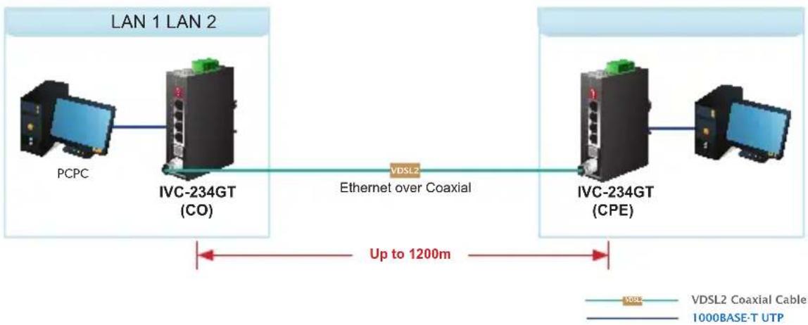
flowchart
graph LR
    A["PCPC"] --> B["IVC-234GT (CO)"]
    B --> C["Ethernet over Coaxial"]
    C --> D["VDSL2 Coaxial Cable"]
    D --> E["IVC-234GT (CPE)"]
    E --> F["Computer"]
    style A fill:#f9f,stroke:#333
    style B fill:#ccf,stroke:#333
    style C fill:#cfc,stroke:#333
    style D fill:#fcc,stroke:#333
    style E fill:#cff,stroke:#333
    style F fill:#ffc,stroke:#333
Connecting Standalone PC
Refer to the following procedures to set up the Industrial Ethernet Extender LAN to LAN connection.
- [LAN1] Set the Industrial Ethernet Extender at LAN 1 in the CO mode from the DIP switch.
- [LAN2] Set the Industrial Ethernet Extender at LAN 2 in the CPE mode from the DIP switch.
- Power on the Industrial Ethernet Extender CO and CPE at both sides by connecting its power source.
- Power, CO and CPE LEDs will illuminate correspondingly.
- Connect coaxial cable from LAN1 IVC-234GT to VDSL BNC port of the LAN2 IVC-234GT.
- VDSL LNK LED will blink to illuminate at both Industrial Ethernet Extenders.
- Connect the IVC-234GT Ethernet LAN port to the other network device via regular Cat.5 UTP cable.
4.2 Point to Multi-point Application (IP surveillance)
Applications of IP Surveillance
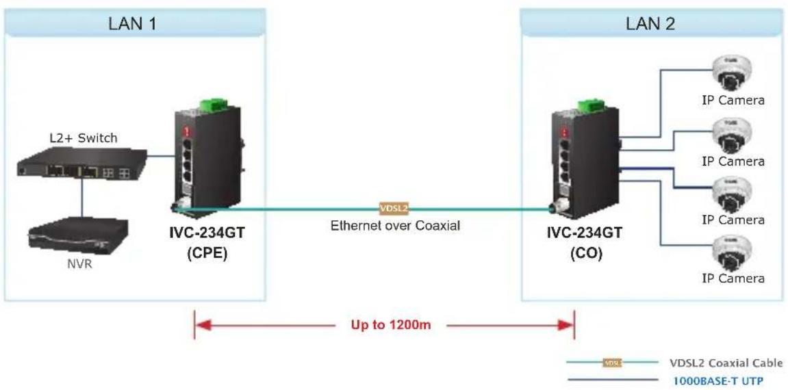
flowchart
graph LR
    subgraph LAN 1
        A["L2+ Switch"] --> B["IVC-234GT (CPE)"]
        C["NVR"] --> B
    end
    subgraph LAN 2
        D["VDSL2 Coaxial Cable"] --> E["IVC-234GT (CO)"]
        F["IP Camera"] --> G["IP Camera"]
        H["IP Camera"] --> I["IP Camera"]
    end
    B <-->|Ethernet over Coaxial| E
    E <-->|Up to 1200m| G
    style LAN 1 fill:#f9f,stroke:#333
    style LAN 2 fill:#ccf,stroke:#333
Building a IP surveillance system
Refer to the following procedure to set up many pairs of IVC-234GT to IP surveillance system.
- Set the IVC-234GT to be the CO and CPE mode from the DIP switch on the front panel.
- Power on the IVC-234GT by connecting its power source.
- Power LED will illuminate.
- Connect coaxial cable from VDSL port of two IVC-234GT units.
- VDSL LED will blink to illuminate.
- Connect Ethernet ports to IP cameras via regular Cat. 5, 5e or 6 cable.
- Install the NVR and monitor and connect to one Ethernet switch.
- You can get data transmissions from all IP cameras.
5. Installations
5.1 Wiring the Power Inputs
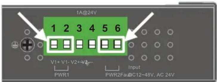
The 6-contact terminal block connector on the top panel of Industrial Ethernet Extender is used for two DC redundant power inputs. Please follow the steps below to insert the power wire.

When performing any of the procedures like inserting the wires or tightening the wire-clamp screws, make sure the power is OFF to prevent from getting an electric shock.
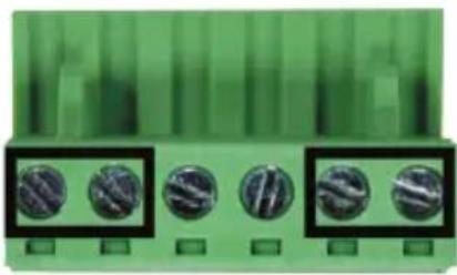
- Insert positive and negative DC power wires into Contacts 1 and 2 for Power 1, or 5 and 6 for Power 2.
- Tighten the wire-clamp screws for preventing the wires from loosening.
natural_image
Green electronic component with five circular buttons arranged in a row (no visible text or symbols)1 2 3 4 5 6 Power 1 Fault Power 2 + - + -

-
The wire gauge for the terminal block should be in the range between 12 and 24 AWG.
-
The DC power input range is 12V \~ 48V DC, 24V AC.
5.2 Wiring the Fault Alarm Contact
The fault alarm contacts are in the middle of the terminal block connector as the picture shows below. Inserting the wires, the Industrial Ethernet Extender will detect the fault status of the power failure and then forms an open circuit. The following illustration shows an application example for wiring the fault alarm contacts.
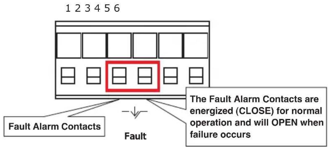
Insert the wires into the fault alarm contacts

-
The wire gauge for the terminal block should be in the range between 12 and 24 AWG.
-
Alarm relay circuit accepts up to 24V, max. 1A currents.
5.3 DIN-rail Mounting Installation
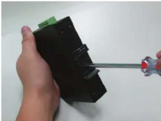
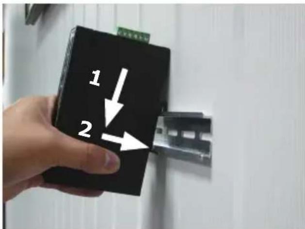
The DIN-rail bracket is screwed on the Industrial Ethernet Extender when out of factory. Please refer to the following steps for DIN-rail mounting:
Step 1: Screw the DIN-rail bracket on the Industrial Ethernet Extender.
natural_image
Hand holding a black electronic device with a screwdriver inserted, no visible text or symbolsStep 2: Lightly insert the bottom of the switch into the track.
Step 3: Make sure the DIN rail is tightly secured on the track.
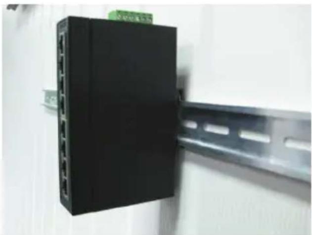
natural_image
Close-up of a black electronic device mounted on a metal frame, no visible text or symbolsStep 4: Please refer to the following procedure to remove the Industrial Ethernet Extender from the track.
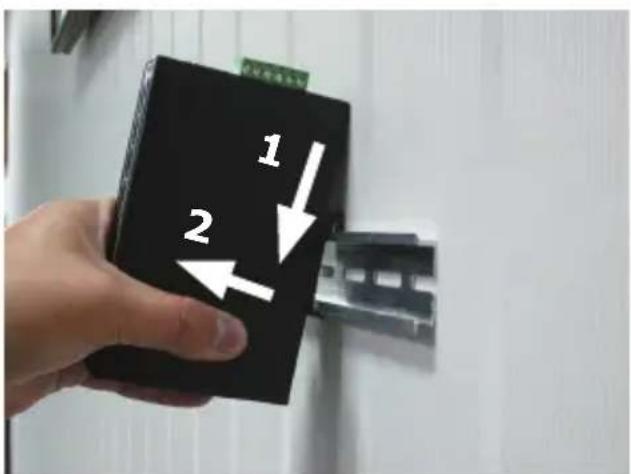
Step 5: Lightly pull out the bottom of DIN rail for removing it from the track.
5.4 Wall-mount Plate Mounting
To install the Industrial Ethernet Extender on the wall, please follow the instructions described below.
Step 1: Remove the DIN-rail bracket from the Industrial Ethernet Extender with a screwdriver.
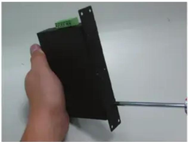
Step 2: Place the wall-mount plate on the rear panel of the Industrial Ethernet Extender.
natural_image
Hand holding a black electronic device with a metal rod extending from it (no visible text or symbols)Step 3: Use the screws to screw the wall-mount plate on the Industrial Ethernet Extender.
Step 4: Use the hook holes at the corners of the wall-mount plate to hang the Industrial Ethernet Extender on the wall.
Step 5: To remove the wall-mount plate, reverse the steps above.
6. Performance Table
■ Industrial Ethernet Extender Upstream/Downstream Performance with RJ11 connection
| CO DIP SwitchDistance (meter) | Interleave(Upstream/Downstream) | |||
| Asymmetric Symmetric | ||||
| 8dB 12dB 8dB 12dB | ||||
| 200 93/190 85/174 143/148 132/136 | ||||
| 400 67/164 59/146 118/119 103/104 | ||||
| 600 38/116 28/94 71/75 59/60 | ||||
| 800 24/59 22/49 49/36 38/27 | ||||
| 1000 9/45 7/40 21/25 15/24 | ||||
| 1200 6/30 3/28 16/24 6/20 | ||||
| CO DIP SwitchDistance (meter) | G.INPUpstream /Downstream) | |||
| Asymmetric Symmetric | ||||
| 8dB 12dB 8dB 12dB | ||||
| 200 92/190 85/174 143/148 129/136 | ||||
| 400 68/165 57/144 116/115 99/96 | ||||
| 600 37/112 28/94 71/69 61/55 | ||||
| 800 27/56 22/49 49/32 39/24 | ||||
| 1000 9/46 7/40 19/27 15/26 | ||||
| 1200 5/31 3/28 16/23 12/20 | ||||
■ Industrial Ethernet Extender Upstream /Downstream Performance with BNC connection
| CO DIP SwitchDistance (meter) | Interleave(Upstream/Downstream) | |||
| Asymmetric Symmetric | ||||
| 8dB 12dB 8dB 12dB | ||||
| 200 84/184 75/169 131/144 125/128 | ||||
| 400 49/148 54/128 93/118 89/99 | ||||
| 600 36/100 26/80 77/66 64/53 | ||||
| 800 21/50 17/39 44/30 37/26 | ||||
| 1000 7/42 5/29 20/25 19/28 | ||||
| 1200 5/27 3/28 13/27 15/20 | ||||
| CO DIP SwitchDistance (meter) | G.INP(Upstream /Downstream) | |||
| Asymmetric Symmetric | ||||
| 8dB 12dB 8dB 12dB | ||||
| 200 89/185 79/166 140/144 117/123 | ||||
| 400 57/155 47/137 104/113 89/96 | ||||
| 600 33/75 31/73 62/73 52/43 | ||||
| 800 17/66 13/45 40/29 39/24 | ||||
| 1000 13/59 6/38 20/27 15/26 | ||||
| 1200 4/32 3/22 14/20 12/20 | ||||
*1 BNC and RJ11 mode must switch to the same position for CO and CPE. Otherwise, it may cause instability.
*2 The actual data rate will vary on the quality of the copper wire and environmental factors.
7. Troubleshooting
SYMPTOM:
VDSL LNK LED does not light up after wire is connected to the VDSL port.
CHECKPOINT:
-
Verify the length of the coaxial cable (not more than 1.2km) connected between the two IVC-234GT units. Please also try to adjust the DIP switch of the IVC-234GT to the other SNR mode.
-
Please note you must use one IVC-234GT in CO mode and the other IVC-234GT in CPE mode to make connection to each other work.
SYMPTOM:
TP LED does not light up after cable is connected to the port.
CHECKPOINT:
- Verify you are using the Cat.5e or better cable with RJ45 connector to connect to the port.
- If your device (like LAN card) supports auto-negotiation, please try to manually set at a fixed speed of your device to solve this issue.
- The IVC-234GT and the connected device's power are on or not.
- The port's cable is firmly seated in its connectors in the switch and in the associated device.
- The connecting cable is good and with the correct type.
- The connecting device, including any network adapter, is functional.
8. FAQs
Q1: What is VDSL2?
A1: VDSL2 (Very High-Bit-Rate Digital Subscriber Line 2), G.993.2 is the newest and most advanced standard of xDSL broadband wire line communications.
Designed to support the wide deployment of Triple Play services such as voice, data, high definition television (HDTV) and interactive gaming, VDSL2 enables operators and carrier to gradually, flexibly, and cost efficiently upgrade the existing xDSL-infrastructure.
Q2: What is SNR and what's the effect?
A2: In analog and digital communications, Signal-to-Noise Ratio, often written as SNR, is a measure of signal strength relative to background noise. The ratio is usually measured in decibels (dB).
In digital communications, the SNR will probably cause a reduction in data speed because of frequent errors that require the source (transmitting) computer or terminal to resend some packets of data. SNR measures the quality of a transmission channel over a network channel. The greater the ratio, the easier it is to identify and subsequently isolate and eliminate the source of noise.
Generally speaking, the higher SNR value gets, the better the line quality gets, but performance is lower.
Q3: What is the best distance for IVC-234GT?
A3: In order to guarantee the stability and better quality of network, we suggest the distance should not exceed 1.2 kilometers.
9. Customer Support
Thank you for purchasing PLANET products. You can browse our online FAQ resource and User's Manual on PLANET Web site first to check if it could solve your issue. If you need more support information, please contact PLANET switch support team.
PLANET online FAQs:
http://www.planet.com.tw/en/support/faq
Switch support team mail address:
Copyright © PLANET Technology Corp. 2018.
Contents are subject to revision without prior notice.
PLANET is a registered trademark of PLANET Technology Corp. All other trademarks belong to their respective owners.
EC Declaration of Conformity
For the following equipment:
*Type of Product : IP30 Industrial Ethernet Extender, 4-Port 10/100/1000T RJ45, 1-Port BNC, 1-Port RJ11
*Model Number : IVC-234GT
* Produced by:
Manufacturer's Name : Planet Technology Corp.
Manufacturer's Address : 10F., No.96, Minquan Rd., Xindian Dist., New Taipei City 231, Taiwan, R.O.C.
is herewith confirmed to comply with the requirements set out in the Council Directive on the Approximation of the Laws of the Member States relating to Electromagnetic Compatibility Directive on (2014/30/EU).
For the evaluation regarding the EMC, the following standards were applied:
EN 55032
(2015 + AC:2016)
EN 55024
(2010 + A1:2015)
EN 55035
(2017)
Responsible for marking this declaration if the:
Manufacturer
☐ Authorized representative established within the EU
Authorized representative established within the EU (if applicable):
Company Name: Planet Technology Corp.
Company Address: 10F., No.96, Minquan Rd., Xindian Dist., New Taipei City 231, Taiwan, R.O.C.
Person responsible for making this declaration
Name, Surname Kent Kang
Position / Title : Director
Taiwan
Place
June 12, 2018
Date
front fang
Legal Signature
- Industrial 1-Port BNC/RJ11 to 4-Port Gigabit Ethernet Extender
- Trademarks
- Disclaimer
- FCC Warning
- CE Mark Warning
- Energy Saving Note of the Device
- WEEE Warning
- Revision
- Table of Contents
- Package Contents
- Hardware Introduction
- Physical Dimensions
- Front View
- Front Panel
- Top View
- IVC-234GT LED Indicators
- DIP Switch and Link Type
- Link Type
- DIP Switch
- ■ DIP-3: Band Profile (Asymmetric/Symmetric)
- ■ DIP-4: SNR (Signal Noise Ratio) Margin
- Product Specifications
- Applications
- Point-to-Point Application -- LAN to LAN Connection
- Connecting Standalone PC
- Point to Multi-point Application (IP surveillance)
- Building a IP surveillance system
- Installations
- Wiring the Power Inputs
- Wiring the Fault Alarm Contact
- DIN-rail Mounting Installation
- Wall-mount Plate Mounting
- Performance Table
- Troubleshooting
- SYMPTOM:
- CHECKPOINT:
- FAQs
- Customer Support
- EC Declaration of Conformity
Brand : Planet
Model : IVC-234GT
Category : Switch